Defect Detection for Wheel-Bearings with Time-Spectral Kurtosis and Entropy

Abstract
: Wheel-bearings easily acquire defects due to their high-speed operating conditions and constant metal-metal contact, so defect detection is of great importance for railroad safety. The conventional spectral kurtosis (SK) technique provides an optimal bandwidth for envelope demodulation. However, this technique may cause false detections when processing real vibration signals for wheel-bearings, because of sparse interference impulses. In this paper, a novel defect detection method with entropy, time-spectral kurtosis (TSK) and support vector machine (SVM) is proposed. In this method, the possible outliers in the short time Fourier transform (STFT) amplitude series are first estimated and preprocessed with information entropy. Then the method extends the SK technique to the time-domain, and extracts defective frequencies from reconstructed vibration signals by TSK filtering. Finally, the multi-class SVM was applied to classify bearing defects. The effectiveness of the proposed method is illustrated using real wheel-bearing vibration signals. Experimental results show that the proposed method provides a better performance in defect frequency detection and classification than the conventional SK-based envelope demodulation.1. Introduction
Wheel-bearings are an essential mechanical component of railway vehicles. The high-speed operating conditions and constant metal-metal contact easily leads to defects, such as axle burn-off, metal losses and cage fragmentation. They can affect the normal operation of railway traffic systems, and ultimately lead to train derailments. Therefore, the detection of bearing defects is of great importance, especially with the great improvements of train speed in recent years.
Vibration or sound signals generated by bearings usually contain rich information. Their corresponding analysis is an effective way to detection defects, and has received wide attention in recent years [1–4]. The above methods can be classified into three categories according to the type of features, namely time-domain, frequency-domain, and time-frequency domain analysis techniques. Time-domain techniques usually calculate statistical features directly from time waveforms. Some scholars have studied in-depth the defect characteristics of roller bearings according to the peak, root mean square (RMS), kurtosis, and duration of the acoustic emission (AE) signals [5–8]. Frequency-domain techniques, such as the Fourier transform, fast Fourier transform (FFT) and spectral kurtosis (SK), have the ability to identify certain interest frequencies and their locations [9–11]. Time-frequency analysis techniques such as wavelet transform [12–15], Wigner-Ville distribution [16], Hilbert-Huang transform (HHT) [17], empirical mode decomposition [18–21], and local mean decomposition (LMD) [22–24] have also been used for fault diagnosis of rotating machinery. In general, time-frequency techniques are effective for non-stationary signals. Furthermore, the classification schemes, such as artificial neural networks [25,26], decision tree [27,28], and support vector machine (SVM) [27,29,30], have also been introduced for identifying different types of bearing faults.
In addition, in recent years some detection systems have been developed with different inspection techniques to identify defective bearings prior to failure. The Hot Bearing Detector (HBD) was developed first. It uses wayside rail-mounted infrared transducers to monitor bearings’ temperatures as a train passes the detector. The system issues an alarm if the bearing operating temperature exceeds a certain threshold. The catastrophic failure of roller bearings happens very quickly and results in axle burn-off, even derailment. Unfortunately, current HBD systems may miss overheated roller bearings.
In order to prevent catastrophic bearing failure, acoustic methods have been employed to identify defective bearings. Among the well-known systems are Railway Bearing Acoustic Monitoring System (RailBAM) and Trackside Acoustic Detection System (TADS). They are developed by VIPAC, Inc. [31], and Transportation Technology Center, Inc. (TTCI) [32], respectively. TADS is a joint effort between the Federal Railroad Administration (FRA) and the Association of American Railroads (AAR) to develop alternative wayside detection systems. It uses microphone arrays to detect interfering airborne acoustic signals from the surrounding train noise and all other wheels. TADS has been successful in detecting a majority of defects at different stages. However, the system still faces challenges in detecting small defects, especially in inward rollers.
Recently, ENSCO, Inc. has investigated a novel technology, which used accelerometers mounted on the rail, designed to detect bearing defects early. They investigated the transmissibility of the vibration signals from defective bearings to rails, a transient mechanical path formed by the bearing, axle, wheel, rail, and accelerometers. The rolling wheel-rail contact patch was considered a challenge for the technology. The data analysis appeared to indicate defective bearing signals could transmit from the bearing down to the accelerometers on the rail. However, the field test was conducted under less than ideal conditions. A credible signal-to-noise ratio (SNR) to allow meaningful detection of bearing defects was not established.
The above systems have an important role in detecting defects, but they cannot discover all potential defects. To fullfil the strict safty regulations of railroads, wheel-bearings require regularly servicing at maintenance workshops. As far as we know, the detection is conducted manually in China. More reliable and automatic detection methods are needed. To realize defect detection and classification accurately, a major challenge is how to find characteristic frequencies of roller bearings. Conventional envelope analysis technique gives an effective extraction method from low SNR vibration signals with a band-pass filter. In practical applications, the resonance frequency band (RFB) for a band-pass filter may vary as the locomotive wheel sets, axles or bearings change. The key problem is how to accurately find the optimal RFB. Antoni et al. [9] investigated and introduced SK to solve this issue. It is shown that SK can indicate not only transient components in signals, but also their locations in the frequency domain, therefore providing the optimal bandwidth for demodulation. However, it may cause false detections when processing real vibration signals collected from wheel-bearings, which usually contain sparse interference impulses.
Based on an in-depth study of SK abnormity, a defect detection method with entropy, time-spectral kurtosis (TSK) and SVM is proposed in this paper. In the method, entropy is introduced to estimate and preprocess possible outliers in STFT amplitude series (STFTAS) of raw vibration signals. Then the SK is extended to the time-domain, and the vibration signal is reconstructed with TSK filtering. The TSK technique can indicate not only the transients in frequency domain, but also their locations in the time domain. Finally, extracted features are used as an input eigenvector of the SVM model to classify bearing defects. Experimental results show that the proposed method could effectively identify defects from real vibration signals collected from wheel-bearings.
2. Spectral Kurtosis and Its Abnormity for Wheel-Bearings
2.1. Definition and Physical Interpretation
Dwyer [33] originally proposed spectral kurtosis for stationary signals as the normalized fourth-order moment of the real part of the Fourier transform. While vibration signals of wheel-bearings are non-stationary. Recently, Antoni et al. [9] proposed the formalization for both stationary and non-stationary signals, and introduced the SK technique into mechanical fault diagnosis. SK has been proven efficient in detecting incipient faults from strong noise, and is widely used in fault diagnosis of roller bearings.
For a given non-stationary signal Y(t), the Word-Cramér’s decomposition is as follows:
Let C4Y(f) and S2nY(f) be the fourth-order spectral cumulants and 2n-order spectral components of non-stationary signal Y(t), respectively, the spectral kurtosis is defined [9]:
Given a non-stationary signal Y(t) and STFT Y(k, f), the SK estimator is defined as follows [9]:
When roller bearings have defects, they will generate a series of impacts and excite the resonance of the structure. The measured vibration signal Z(t) and real defect signal Y(t) can be expressed as follows, respectively:
If N(t) is an additive stationary noise independent of Y(t), then SK is:
If N(t) is an additive stationary Gaussian noise independent of Y(t), then SK is:
From Equation (9), we can see the value of SKZ(f) is similar to SKY(f) at frequencies with high SNR. If the SNR is very low, it is close to zero. Therefore, SK value directly indicates the SNR of defective signal at each frequency, and can find the RFB of vibration signal automatically while designing a band-pass filter.
2.2. The Abnormity for Wheel-Bearings
SK could detect the transients in non-stationary signals, and indicate the locations in the frequency domain by calculating the kurtosis of each spectral line. However, when processing the real vibration signals collected from wheel-bearings, we found that RFBs selected by the SK technique cannot always detect defective frequencies. This may be caused by sparse interference impulses, which are usually caused by the impurities in the lubricant oil, striking of wheel-sets, and surrounding constructions at the wheel maintenance workshop.
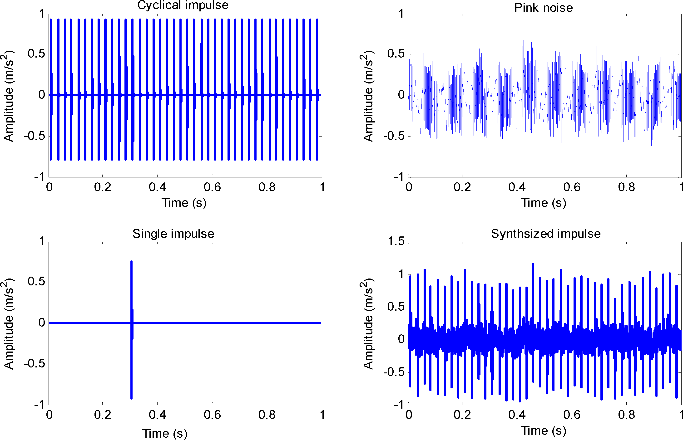
To study the effect of interference impulses on the SK technique, we first simulated a synthesized signal as shown in Figure 1. It is composed of pink noise, a single impulse with the center frequency at 10 kHz, and cyclical impulses with the center frequency at 4 kHz, which simulates the defect on outer the race with a 40 Hz characteristic frequency. The sampling frequency is 32,768 Hz. In the simulation, we choose the Hanning window and set parameters N = 128, p = 32. In addition, the block size N was chosen according to the duration of impulses and the minimum resolution of defective frequencies. We have considered other block sizes. The value of SK varies with different block sizes. For example, the SK value would be smaller as the block size increases. However, the relative change trend is consistent.
The results of SK and envelope demodulation analysis of the synthesized signal are shown in Figure 2. We can obviously see the SK value of an interference impulse (10 kHz) is larger than the defective impulse (4 kHz). If we select RFB according to the maximum value of SK, we cannot discover the defect frequency of interest at 40 Hz after envelope demodulation. However, the defective frequency of the outer race (DFOR) and its corresponding harmonics (2DFOR, 3DFOR, 4DFOR) can be clearly observed using the correct 3.5–4.5 kHz bandwidth for demodulation.
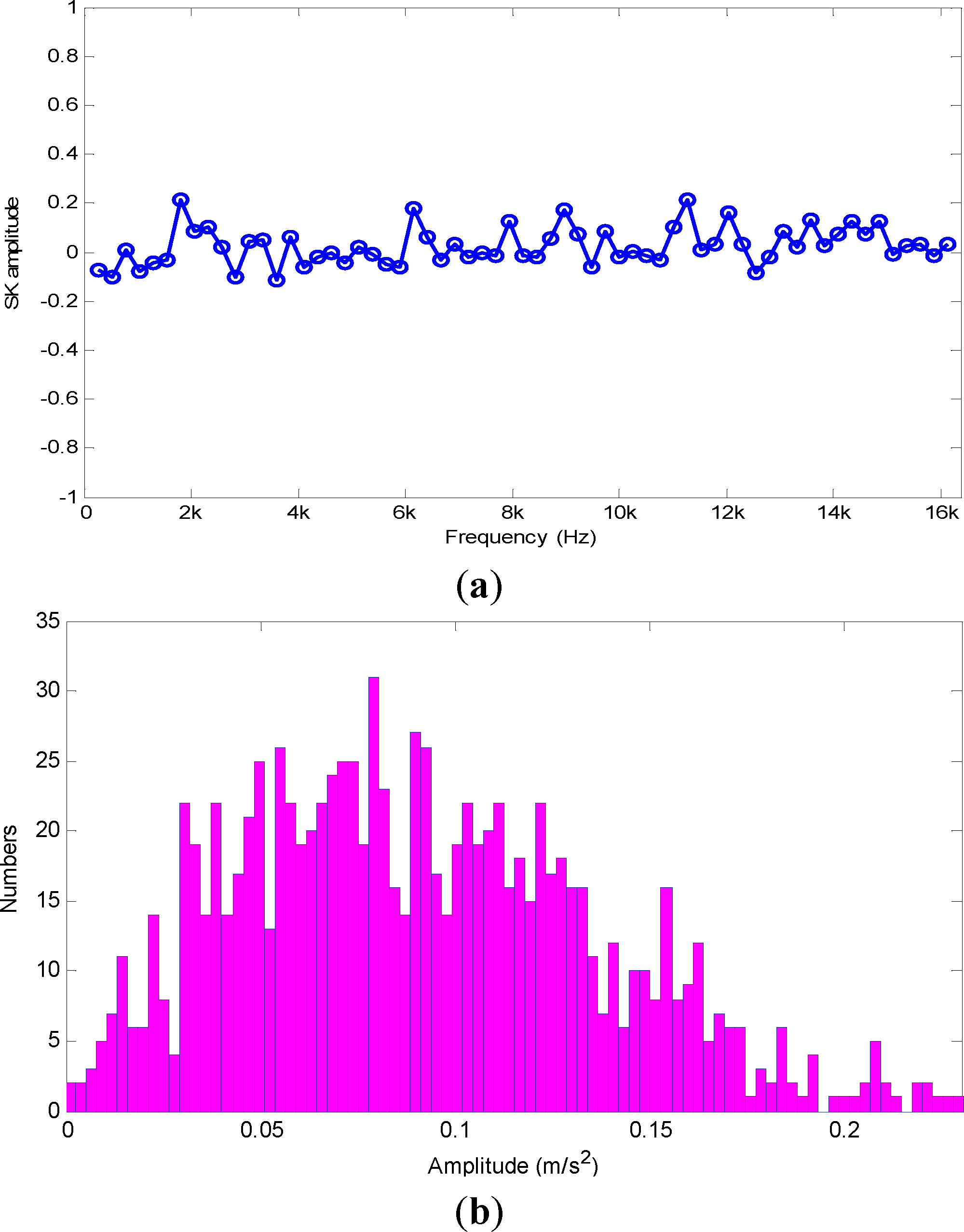
To study in depth the amplitude and intensity of interference impulses influenced on the SK technique, a new series s(n) = [y(k),z] is constructed, where y(k) = |Y(kp, f)| denotes the STFTAS of a white Gaussian signal at frequency f, and z is a positive value which denotes an intensive impulse. Similarly, the SK value can be calculated as:
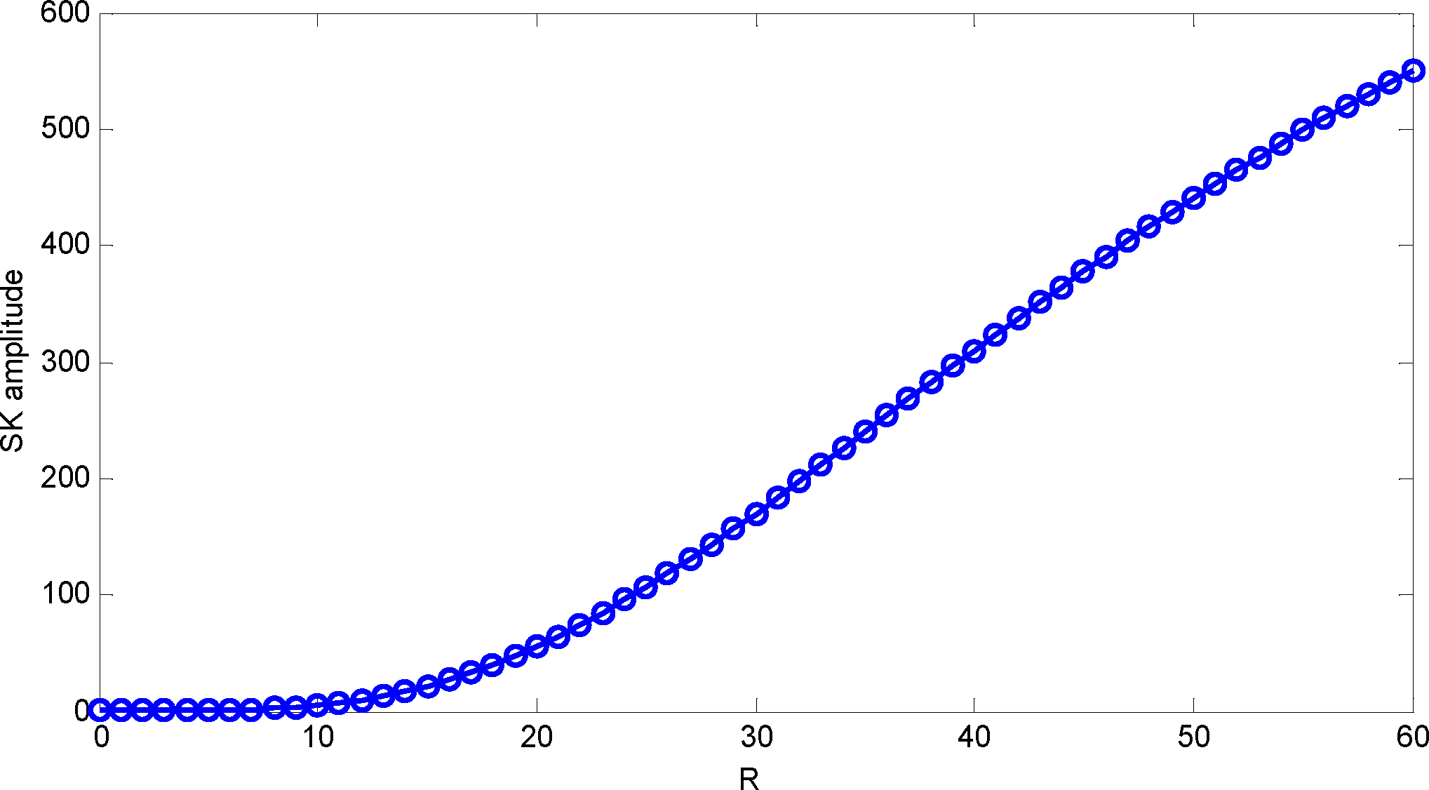
Figure 3 gives the SK and statistical distributions of a white Gaussian signal. We can see the values of SK are near zero, which conforms to the theoretical value. Figure 3(b) denotes the statistical distribution of STFTAS for a white Gaussian signal at certain frequencies. For other frequencies, their distributions are similar and approximately symmetrical. Figure 4 shows the SK amplitude varying with different . It increases exponentially as R is greater than 10. That is to say, the SK value will become large greatly as an outlier far away from initial statistical distribution. We consider it an abnormity phenomenon of SK. In addition, the SK value depends on relative but not absolute values of interference impulses.
3. Feature Extraction with Time-Spectral Kurtosis and Entropy
3.1. Estimation of Possible Outliers with Entropy
In 1948, Shannon proposed entropy to characterize information hidden in data [34]. In general, the entropy increases with the degree of disorder and reaches the maximum for a completely random system (Gaussian random variables). It is determined by the power spectrum density of the signals in the probability density function. There are several ways to calculate entropy, such as the approximate entropy, spectral entropy, multi-scale entropy, energy entropy. They are widely applied in feature extraction and fault diagnosis of machinery [35–38].
The advantage of entropy is introduced to estimate possible outliers in STFTAS. Let |Y(ti,fj)|, (i = 1,⋯, K; j = 1,⋯, N) be the STFTAS of raw vibration signals at time block ti and frequency fj, the probability density function of time series at frequency f is then defined as:
The entropy is thus formulated as:
The corresponding normalization with different frequencies is defined as:
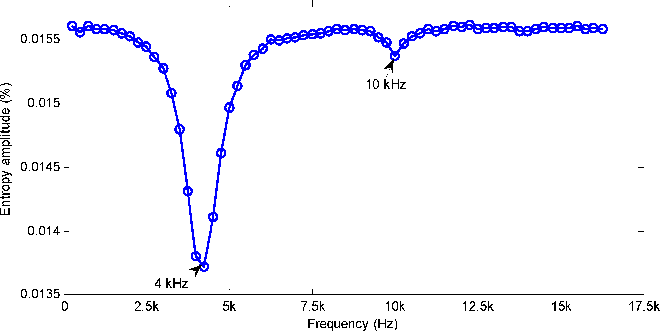
According to Equation (13), the entropy of the synthesized signal can be calculated as shown in Figure 5. There is a sharp decline of about 11.8% at 4 kHz. By contrast, it has an obvious but slight drop of 1.1% at 10 kHz. Therefore, entropy can be used to estimate the possible outliers in STFTAS. That is to say, it contains real defect information only if the entropy value declines beyond a certain degree. Otherwise, it is due to interference and needs to be preprocessed.
On the basis of above principles, this paper gives a realization method by replacing those large value points with near one. Among them, the ratio Poutlier is decided by the entropy value. Figure 6 shows the statistical distribution of synthesized signal at different frequencies (Poutlier = 1.0%). We can see:
- (1)
At 2 kHz, the statistical distribution has no change after preprocessing the outliers in signals, which mainly contains the pink noise. Its shape is similar to the white Gaussian signal as shown in Figure 3(b).
- (2)
As the signal mainly contains defect information at 4 kHz, the statistical distribution has also no obvious change after preprocessing.
- (3)
In contrast, the statistical distribution changes notably after preprocessing at 10 kHz, which mainly contains a single interference impulse. It can be concluded that it mainly changes the distribution of random interference impulse.
3.2. Proposed Time-Spectral Kurtosis Filtering
The SK estimator depends only on statistical distribution of amplitude series, but has nothing to do with time information. In fact, the appearance of defective impulses in vibration signal is regular and periodic. However, SK has no reflection on time-domain information. In this section, motivated by previous SK efforts, we extend SK further to time-domain with entropy analysis, and propose a time-spectral kurtosis filtering method.
The definition of time-spectral kurtosis is:
Detailed TSK-based filtering can be summarized as follows.
Step 1: The STFT of raw vibration signal is calculated.
Step 2: The outliers are preprocesed with entropy for the STFTAS.
Step 3: The Gaussian component G (m, f) is estimated from preprocessed STFTAS. Firstly, the mean value of STFT amplitude series is calculated. Then finding points whose amplitude is less than n-times mean, and constructing a new series with these selected points. By through of several iterative computations, the objective series with approximate Gauss distribution can be obtained.
Step 4: Yhe TSK value of k-th frame signal at frequency f is calculated with |Y(k, f)| and G(m, f) according to Equation (14).
Step 5: The filter H(k, f) is deesigned according to the TSK value.
Step 6: The signal reconstruction by H(k, f) multiplying STFT values.
Step 7: Demodulation of the reconstructed signal using the Hilbert transformation.
3.3. Defective Frequency Calculation
If roller bearings have defects on the inner race, outer race or balls, it generates a series of periodic vibrations as a running roller passes over the surfaces of the defects. These vibrations occur at certain characteristic frequencies, which are determined by the rotational speed, locations of defects, and geometric parameters [1]. For a given bearing with stationary outer race, these defective frequencies are given as follows:
Defective frequency of the outer race fOR:
Defective frequency of the inner race (DFIR) fIR:
Defective frequency of the roller element (DFRE) fRE:
Defective frequency of the cage (DFC) fC:
In order to reduce the influence caused by the slight change of motor speed, the maximum values are chosen in intervals [fOR + δ, fOR − δ], [fIR + δ, fIR − δ], [fRE + δ, fRE − δ], and [fC + δ, fC − δ] Hz as the feature of DFOR, DFIR, DFRE and DFC, respectively. These characteristic frequencies are constructed into an eigenvector, used as the input eigenvector of the SVM model to recognize and classify bearing defects. The parameter δ depends on the frequency resolution and the variation range of speed.
4. Experiments and Analysis
In this section, the effectiveness of proposed method is illustrated by the vibration signals collected from real wheel-bearings at the Xuzhou Wheel Maintenance Workshop, Jiangsu Province, China.
4.1. Test-Rig and Data Acquisition
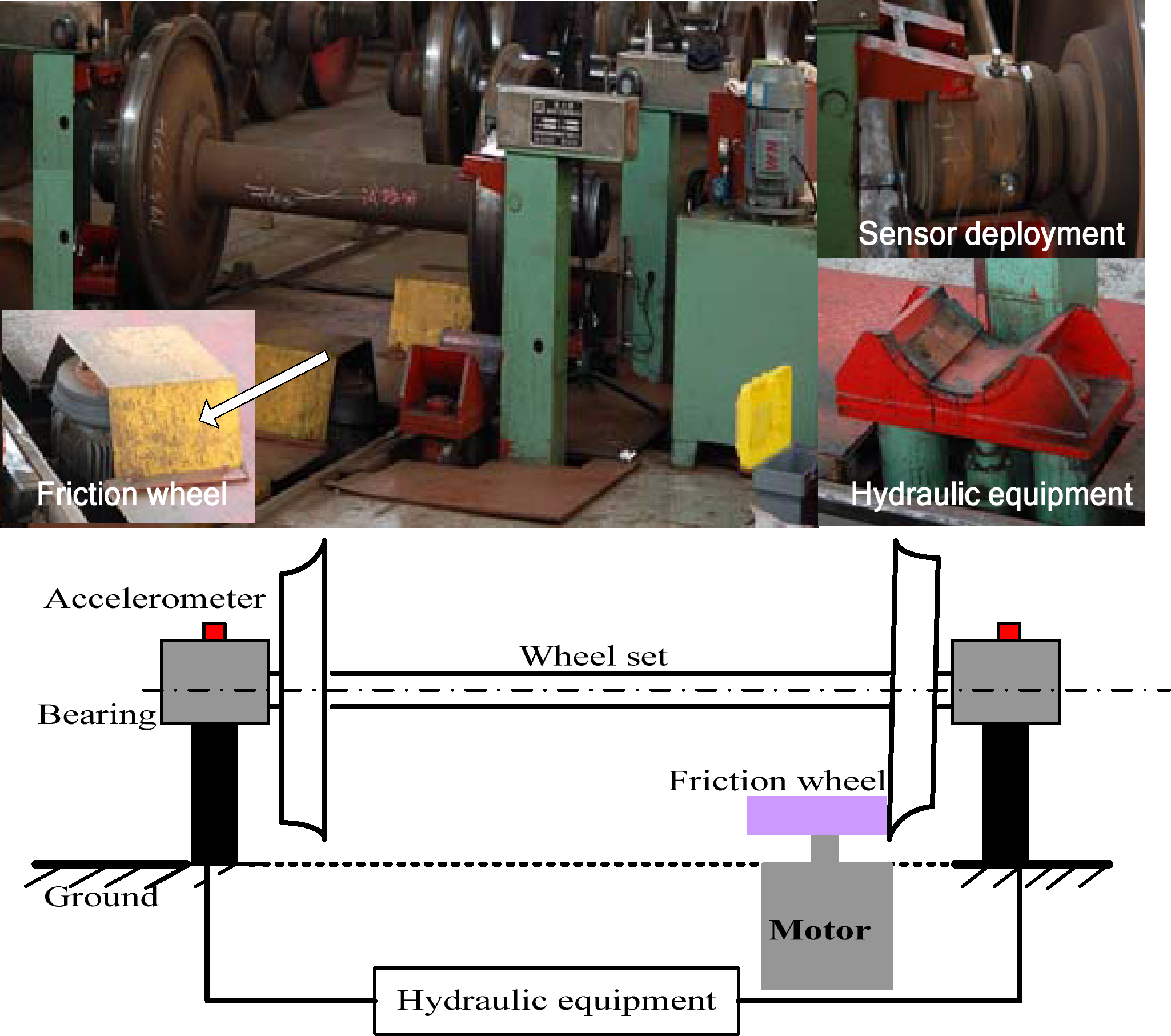
Figure 7 shows the structure of the wheel-bearing test-rig, which consists of a motor, hydraulic equipment, a friction wheel, a wheel set, and accelerometers. The wheel set is uplifted by hydraulic equipment, and runs at 245 rpm. Vibration signals were collected through accelerometers using a B&K PULSE instrument (6-channels) with sampling frequency 32,768 Hz. In addition, the accelerometers were mounted on the surface of outer race at 3 and 12 o’clock positions. Detailed geometric parameters of wheel-bearings and experimental parameters are listed in Table 1. According to Equations (16)–(19), characteristic frequencies of the wheel-bearing system at speed 245 rpm are calculated, and given in Table 2.
4.2. Defective Frequency Analysis for Real Wheel-Bearing
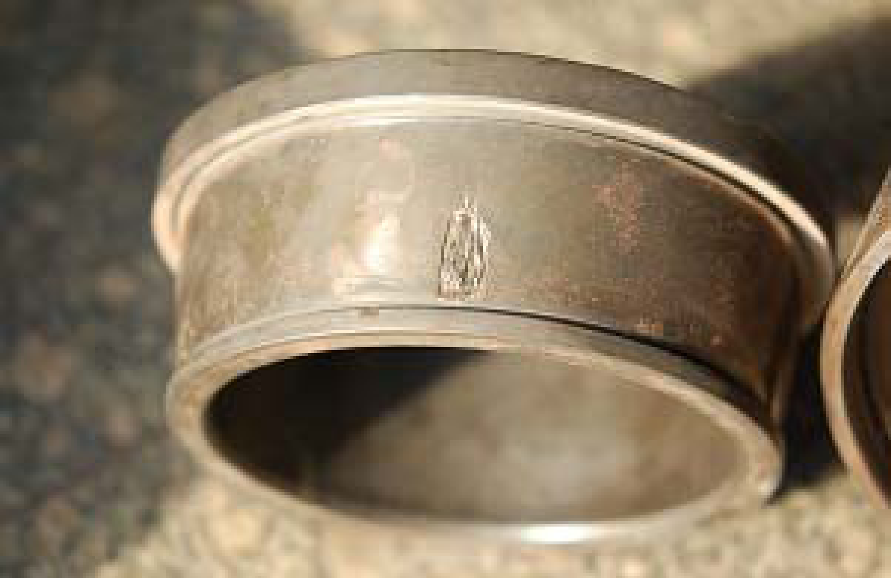
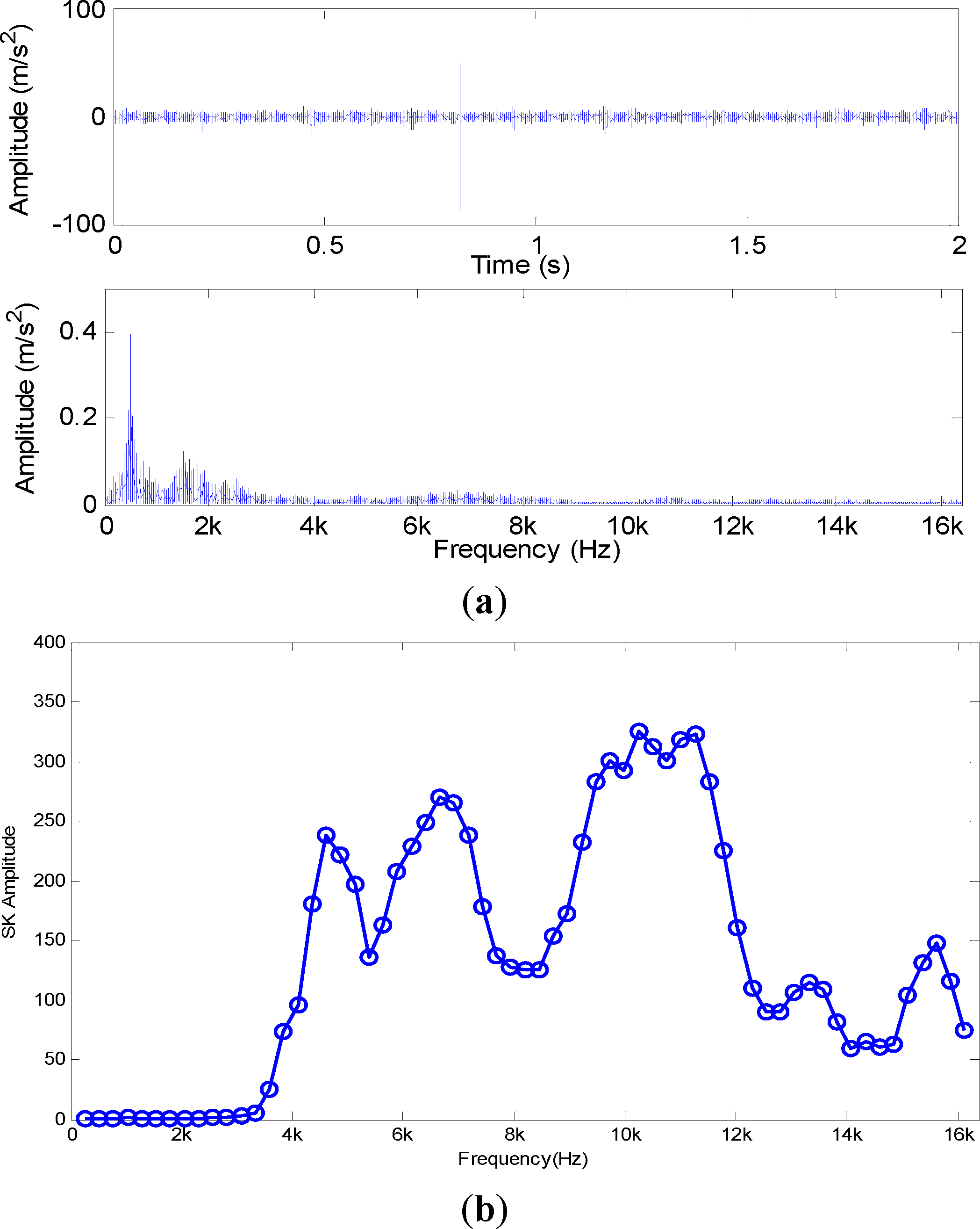
Figure 8 shows an image of a real inner race fault bearing. The waveform, spectrum, SK, TSK and DFIR features extracted from collected vibration signals are shown in Figure 9.
The SNR of the defective signals is low, except for two strong impulses in the time-domain. According to Equation (4), the SK values with STFT are shown in Figure 9(b). It increases significantly beyond 4 kHz. This phenomenon conflicts with the real conditions of the defective signal. In fact, it mainly reflects the spectrum structure of two strong impulses. Therefore, it cannot indicate the correct RFB of wheel-bearings. The reason for this phenomenon is that conventional SK technique is much sensitive to sparse large interference impulses in signals. By contrast, the TSK value is very small in Figure 9(c). It reflects the real SNR of vibration signals.
Band-pass filtering is firstly implemented to extract the envelope signal according to the maximum value of SK. After demodulation, the corresponding spectrum zoomed in 0–100 Hz is illustrated in Figure 9(d). The DFIR feature can be more clearly discenrned by the TSK than by the SK-based envelope demodulation. Moreover, the sidebands, clearly detected with the TSK method, have the bandwidth of twice the rotational frequency.
In addition, vibration signals collected from an outer race fault bearing, shown in Figure 10, are also analyzed. Figure 11 gives the results of waveform, spectrum, SK, TSK from vibration signals. The spectra obtained by TSK filtering and SK-based envelope demodulation are presented in Figure 11(d), respectively. It can be seen that our proposed method provides better abilities of DFOR detection than SK-based envelope demodulation. Moreover, the second harmonic 2DFOR (about 71 Hz) can be seen clearly, having greater energy. However, this phenomenon doesnot always exist for different testing bearings. Therefore, this feature is not stable for classification.
4.3. Defect Classification with SVM
In this section, a dataset collected from the test-rig is used to illustrate the effectiveness of the proposed method. It consists of four conditions, namely normal state, inner race fault, outer race fault and roller fault. For each condition, 30 samples were used, and the dataset contains 120 samples. Each sample is a section of vibration signal containing 65,536 sampling points. In addition, cage defecta are rare because of the improvement in materials, and we don’t have this type of samples.
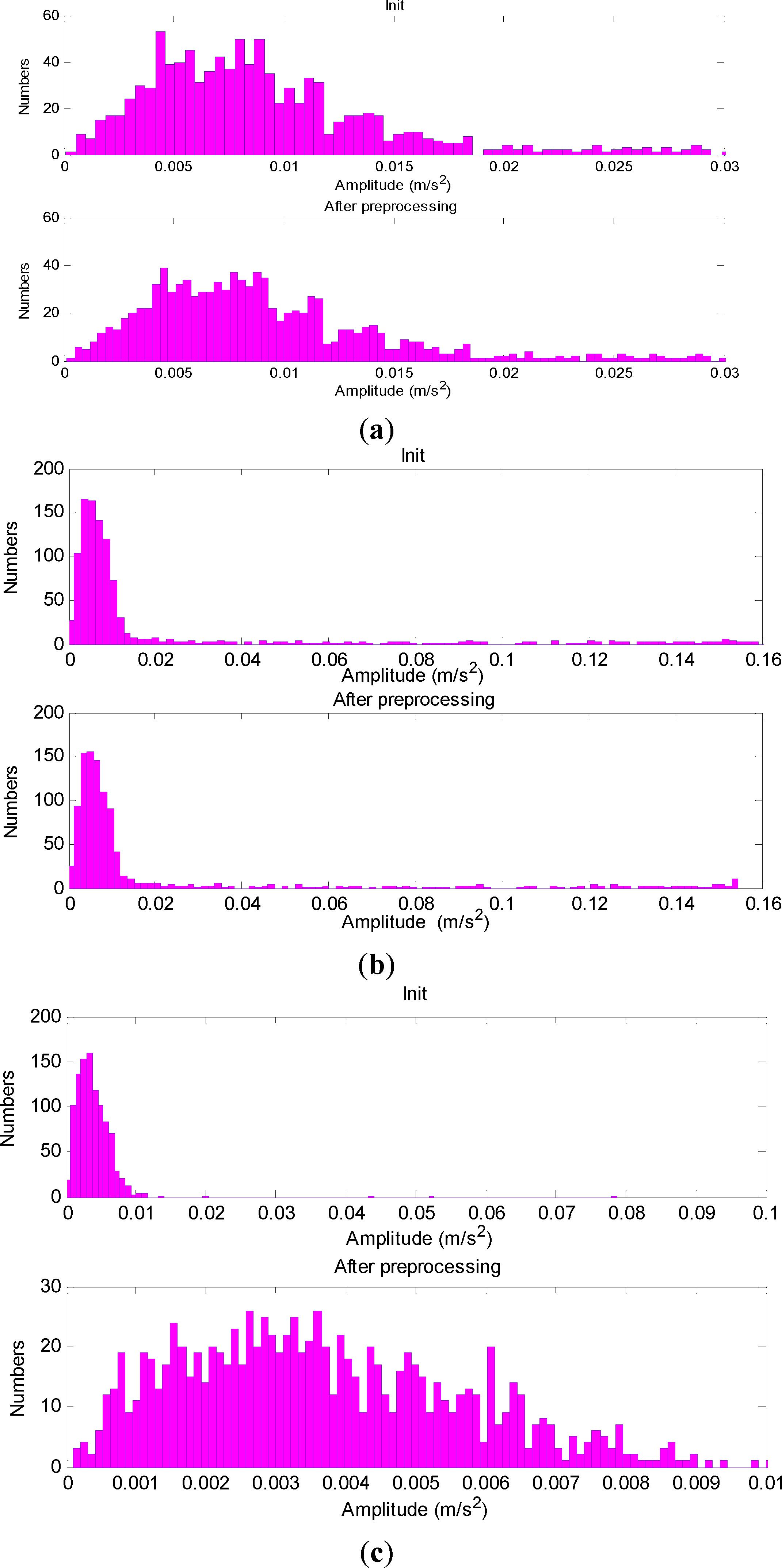
Considering a frequency resolution of 0.5 Hz (32768/65536), variation range of speed and the defective frequencies in Table 2, the maximum value in intervals [35 36], [45.5 46.5], and [14.5 15.5] Hz are chosen as the DFOR, DFIR and DFRE, respectively. These features are used to construct an input eigenvector for the classifier. The distributions of extracted features with TSK and SK-based envelope demodulation are given in Figure 12. As applying with the SK technique, the samples have serious overlap among the four conditions. By contrast, they are separated and have better aggregation with the proposed method.
We choose the multi-class SVM technique (one-versus-one) to classify different conditions, and adopt LIBSVM software [39]. In experiment, 60% of each class samples were randomly selected as training set, and the remaining samples are used for prediction. In addition, the accuracy of prediction is the average of 50 tests. The predicted results with extracted features are presented in Table 3.
From Table 3, as applying with the SK-based method, the classification accuracies for normal state, inner race fault, outer race fault and ball fault are 76.33%, 83.17%, 86.50% and 80.67%, respectively. The overall average classification accuracy is 81.67%. By contrast, the average accuracy is 98.04% with TSK filtering technique, which increases the recognition accuracy by 17.57%. It is concluded that proposed method provides a higher accuracy in defect classification than SK-based envelope demodulation. Therefore, it is more robust for interference impulses at the wheel-bearing maintenance workshop.
However, there are still a small percentage (about 1.96%) of false positives. Furthermore, it has the highest false classification accuracies (3.5%) for the normal state. That is to say, about 3.5% normal samples are misclassified as faults. In previous experiments, we found that impurities in the lubricant oil for normal wheel-bearings may also produce defective frequencies, especially outer race ones, which will lead to the errors in classification. In our future work, we will study how to distinguish impurities from defects.
5. Conclusions
Based on an in-depth study of the SK abnormity for real wheel-bearings, a defect detection method with entropy, time-spectral kurtosis and SVM has been investigated. Through entropy, it can effectively estimate and preprocess outliers in STFTAS, and reduce the influence of interference impulses on characteristic frequency extraction greatly. The TSK filtering technique extends SK to the time-domain, and is sensitive to the relatively slight variations caused by the positive value under low-SNR conditions. Real vibration signals collected from wheel-bearings at a maintenance workshop are measured for validating the effectiveness of the proposed method. Experimental results show that the method provides a higher accuracy for the defective frequency detection, and classifies four conditions of roller bearings more accurately than the conventional SK-based envelope demodulation. In addition, the proposed method has better generalization and robustness for interference impulses in railway applications.
Acknowledgments
This work is supported by the National Natural Science Foundation of China (Grant No. 11304019).
Conflicts of Interest
The authors declare no conflict of interest.
References
- Tandon, N.; Choudhury, A. A review of vibration and acoustic measurement methods for the detection of defects in rolling element bearings. Tribol. Int 1999, 32, 469–480. [Google Scholar]
- Jardine, A.K.S.; Lin, D.; Banjevic, D. A review on machinery diagnostics and prognostics implementing condition-based maintenance. Mech. Syst. Signal. Process 2006, 20, 1483–1510. [Google Scholar]
- Lei, Y.G.; He, Z.J.; Zi, Y.Y. Fault diagnosis of rotating machinery based on multiple ANFIS combination with GAs. Mech. Syst. Signal Process 2007, 21, 2280–2294. [Google Scholar]
- Zhou, R.; Bao, W.; Li, N.; Huang, X.; Yu, D.R. Mechanical equipment fault diagnosis based on redundant second generation wavelet packet transform. Digit. Signal Process 2010, 20, 276–288. [Google Scholar]
- Choudhury, A.; Tandon, N. Application of acoustic emission technique for the detection of defects in rolling element bearings. Tribol. Int 2000, 33, 39–45. [Google Scholar]
- Al-Ghamdi, A.M.; Mba, D. Comparative experimental study on the use of acoustic emission and vibration analysis for bearing defect identification and estimation of defect size. Mech. Syst. Signal Process. 2006, 20, 1537–1571. [Google Scholar]
- Al-Dossary, S.; Hamzah, R.I.R.; Mba, D. Observations of changes in acoustic emission waveform for varying seeded defect sizes in a rolling element bearing. Appl. Acoust 2009, 70, 58–81. [Google Scholar]
- Elforjani, M.; Mba, D. Accelerated natural fault diagnosis in slow speed bearings with acoustic emission. Eng. Fract. Mech 2010, 77, 112–127. [Google Scholar]
- Antoni, J. The Spectral Kurtosis: A useful tool for characterising nonstationary signals. Mech. Syst. Signal Process 2006, 20, 282–307. [Google Scholar]
- Wang, Y.; Liang, M. An adaptive SK technique and its application for fault detection of rolling element bearings. Mech. Syst. Signal Process 2011, 25, 1750–1764. [Google Scholar]
- Randall, R.B.; Antoni, J. Rolling element bearing diagnostics-A tutorial. Mech. Syst. Signal Process 2011, 25, 485–520. [Google Scholar]
- Tse, P.W.; Peng, Y.H.; Yam, R. Wavelet analysis and envelope detection for rolling element bearing fault diagnosis-their effectiveness and flexibilities. J. Vib. Acoust 2001, 123, 303–311. [Google Scholar]
- Peng, Z.K.; Chu, F.L. Application of wavelet transform in machine condition monitoring and fault diagnostics: A review with bibliography. Mech. Syst. Signal Process 2003, 17, 199–221. [Google Scholar]
- Rubini, R.; Meneghetti, U. Application of the envelope and wavelet transform analysis for the diagnosis of incipient faults in ball bearings. Mech. Syst. Signal Process 2001, 15, 287–302. [Google Scholar]
- Qiao, H.; He, Z.J.; Zhang, Z.S.; Zi, Y.Y. Fault diagnosis of rotating machinery based on improved wavelet package transform and SVMs ensemble. Mech. Syst. Signal Process 2007, 21, 688–705. [Google Scholar]
- Baydar, N.; Ball, A. A comparative study of acoustic and vibration signals in detection of gear failures using Wigner-Ville distribution. Mech. Syst. Signal Process 2001, 15, 1091–1107. [Google Scholar]
- Rai, V.K.; Mohanty, A.R. Bearing fault diagnosis using FFT of intrinsic mode functions in Hilbert-Huang transform. Mech. Syst. Signal Process 2007, 21, 2607–2615. [Google Scholar]
- Yu, D.J.; Cheng, J.S.; Yang, Y. Application of EMD method and Hilbert spectrum to the fault diagnosis of roller bearings. Mech. Syst. Signal Process 2005, 19, 259–270. [Google Scholar]
- Wu, F.J.; Qu, L.S. Diagnosis of subharmonic faults of large roating machinery based on EMD. Mech. Syst. Signal Process 2009, 23, 467–475. [Google Scholar]
- Lei, Y.; He, Z.; Zi, Y. EEMD method and WNN for fault diagnosis of locomotive roller bearings. Expert Syst. Appl 2011, 38, 7334–7341. [Google Scholar]
- Guo, W.; Tse, P.W.; Djordjevich, A. Faulty bearing signal recovery from large noise using a hybrid method based on spectral kurtosis and ensemble empirical mode decomposition. Measurement 2012, 45, 1308–1322. [Google Scholar]
- Smith, J.S. The local mean decomposition and its application to EEG perception data. J. R. Soc. Interface 2005, 2, 443–454. [Google Scholar]
- Liu, Z,W.; Chen, X.F.; He, Z.J.; Shen, Z.J. LMD method and multi-class RWSVM of fault diagnosis for rotating machinery using condition monitoring information. Sensors 2013, 13, 8679–8694. [Google Scholar]
- Cheng, S.; Zhang, K.; Yang, Y. An order tracking technique for the gear fault diagnosis using local mean decomposition method. Mech. Mach. Theor 2012, 55, 67–76. [Google Scholar]
- Lei, Y.G.; Zuo, M.J.; He, Z.J.; Zi, Y.Y. A multidimensional hybrid intelligent method for gear fault diagnosis. Expert Syst. Appl 2010, 37, 1419–1430. [Google Scholar]
- Castejón, C.; Lara, O.; García-Prada, J.C. Automated diagnosis of rolling bearings using MRA and neural networks. Mech. Syst. Signal Process 2010, 24, 289–299. [Google Scholar]
- Saimurugan, M.; Ramachandran, K.I.; Sugumaran, V.; Sakthivel, N.R. Multi component fault diagnosis of rotational mechanical system based on decision tree and support vector machine. Expert. Syst. Appl 2011, 38, 3819–3826. [Google Scholar]
- Sun, W.X.; Chen, J.; Li, J.Q. Decision tree and PCA-based fault diagnosis of rotating machinery. Mech. Syst. Signal. Process 2007, 21, 1300–1317. [Google Scholar]
- Yang, Y.; Yu, D.; Cheng, J. A fault diagnosis approach for roller bearing based on IMF envelope spectrum and SVM. Measurement 2007, 40, 943–950. [Google Scholar]
- Zhang, Y.; Qin, Y.; Xing, Z.Y.; Jia, L.M; Cheng, X.Q. Roller bearing safety region estimation and state identification based on LMD–PCA–LSSVM. Measurement 2013, 46, 1315–1324. [Google Scholar]
- Southern, C.; Rennison, D.; Kopke, U. RailBAM-An advanced bearing acoustic monitor: Initial operational performance results. Proceedings of Conference on Railway Engineering, Darwin, Australia, 20–23 June, 2004; pp. 23.01–23.07.
- Anderson, G.B.; Cline, J.E.; Smith, R.L. Acoustic detection of rail car roller bearing defects: Phase III, system evaluation test; Report DOT/FRA/ORD-00/06.III.; Transportation Technology Center, Inc.: Washington, DC, USA, 2003. [Google Scholar]
- Dwyer, R.F. Detection of non-Gaussian signals by frequency domain kurtosis estimation. Proceedings of International Conference on Acoustics, Speech, and Signal Processing, Boston, MA, USA, 14–16 April 1983; pp. 607–610.
- Shannon, E.C. A mathematical theory of communication. Bell Syst. Tech. J 1948, 27, 379–423. [Google Scholar]
- Powell, G.E.; Percival, I.C. A spectral entropy method for distinguishing regular and irregular rmotion of hamiltonian systems. J. Phys. A-Math. Gen 1979, 12, 2053–2071. [Google Scholar]
- Yan, R.; Gao, R.X. Approximate entropy as a diagnosis tool for machine health monitoring. Mech. Syst. Signal Process 2007, 21, 824–839. [Google Scholar]
- Costa, M.; Goldberger, A.L.; Peng, C.K. Multiscale entropy analysis of complex physiologic time series. Phys. Rev. Lett 2002, 89, 068102:1–068102:4. [Google Scholar]
- Zhang, L.; Xiong, G.; Liu, H.; Zou, H.; Guo, W. Bearing fault diagnosis using multi-scale entropy and adaptive Neuro-Fuzzy inference. Expert Syst. Appl 2010, 37, 6077–6085. [Google Scholar]
- Chang, C.C.; Lin, C.J. LIBSVM: A library for support vector machines. ACM Trans. Intell. Syst. Technol 2011, 2, 27:1–27:27. [Google Scholar]


| Contents | Value |
|---|---|
| Type of wheel-bearing | 197726 |
| Contact angle | 10° |
| Diameter of roller | 23.776 mm |
| Pitch diameter | 180 mm |
| Number of rollers | 20 |
| Sampling frequency | 32,768 Hz |
| Rotational speed | 245 rpm |
| Type of accelerometer | Lance2052 |
| Threshold of TSK value | 0.3 |
| Proportion Poutlier | 0.8% |
| Data length | 65,536 |
| Contents | Value |
|---|---|
| DFOR | 35.5216 Hz |
| DFIR | 46.1450 Hz |
| DFRE | 15.1952 Hz |
| DFC | 1.7761 Hz |
| Extraction Methods | Average accuracy | Recognition results | |||
|---|---|---|---|---|---|
| Normal | Inner race | Outer race | Ball fault | ||
| SK-based method | 81.67% | 76.33% | 83.17% | 86.50% | 80.67% |
| Proposed method | 98.04% | 96.50% | 98.17% | 99.67% | 97.83% |
© 2014 by the authors; licensee MDPI, Basel, Switzerland This article is an open access article distributed under the terms and conditions of the Creative Commons Attribution license (http://creativecommons.org/licenses/by/3.0/).
Share and Cite
Chen, B.; Yan, Z.; Chen, W. Defect Detection for Wheel-Bearings with Time-Spectral Kurtosis and Entropy. Entropy 2014, 16, 607-626. https://0-doi-org.brum.beds.ac.uk/10.3390/e16010607
Chen B, Yan Z, Chen W. Defect Detection for Wheel-Bearings with Time-Spectral Kurtosis and Entropy. Entropy. 2014; 16(1):607-626. https://0-doi-org.brum.beds.ac.uk/10.3390/e16010607
Chicago/Turabian StyleChen, Bin, Zhaoli Yan, and Wei Chen. 2014. "Defect Detection for Wheel-Bearings with Time-Spectral Kurtosis and Entropy" Entropy 16, no. 1: 607-626. https://0-doi-org.brum.beds.ac.uk/10.3390/e16010607