Depth Image Coding Using Entropy-Based Adaptive Measurement Allocation

Abstract
:1. Introduction
2. Proposed Scheme
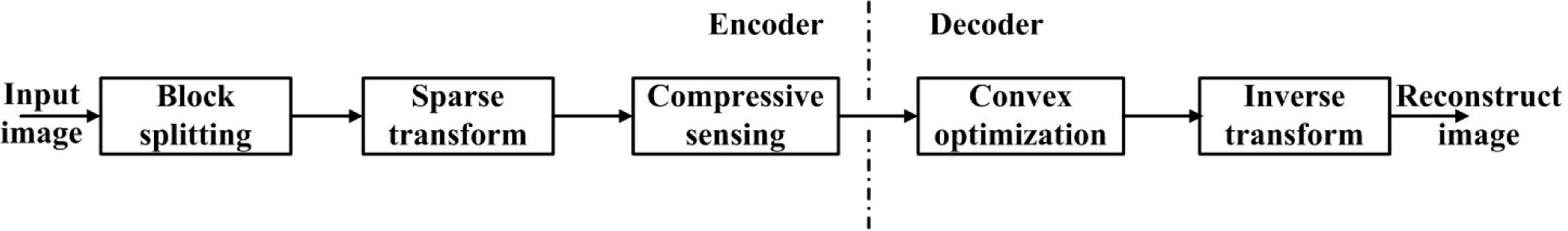
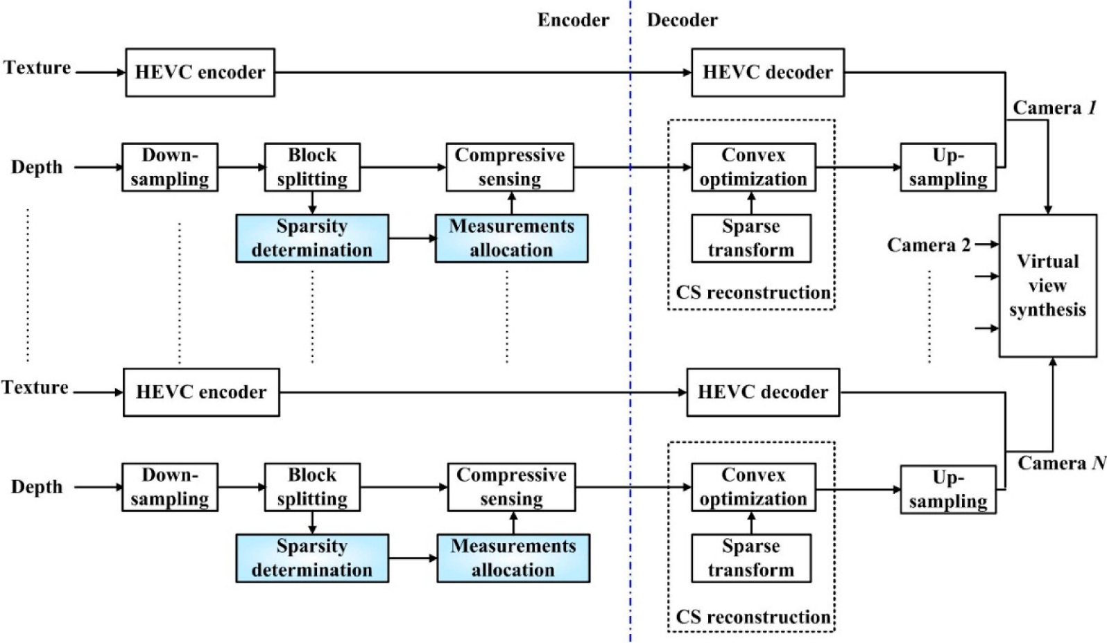
2.1. Overview
2.2. Basic Idea of CS
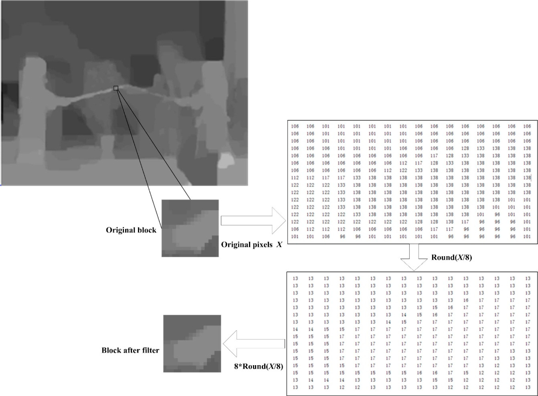
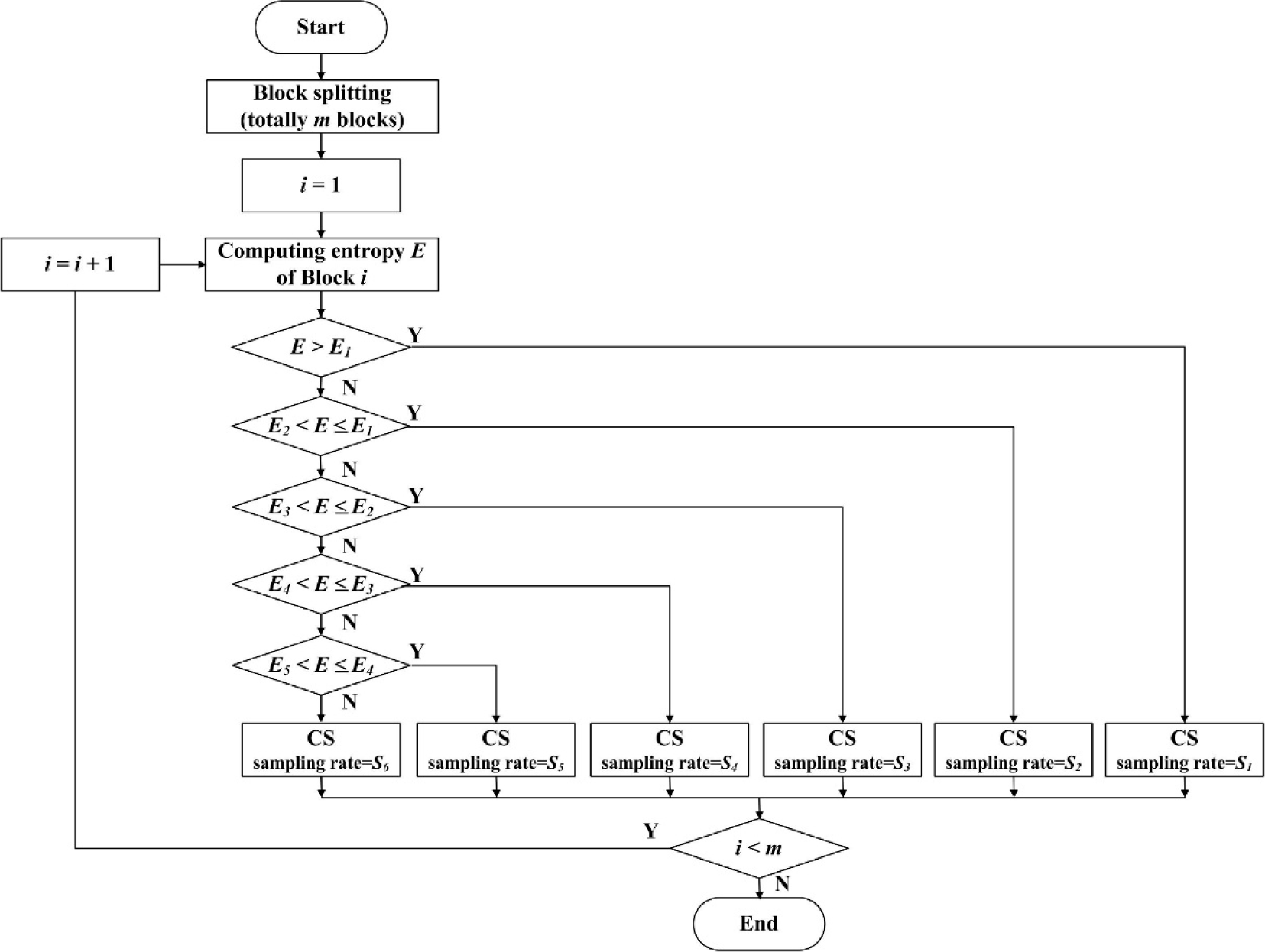
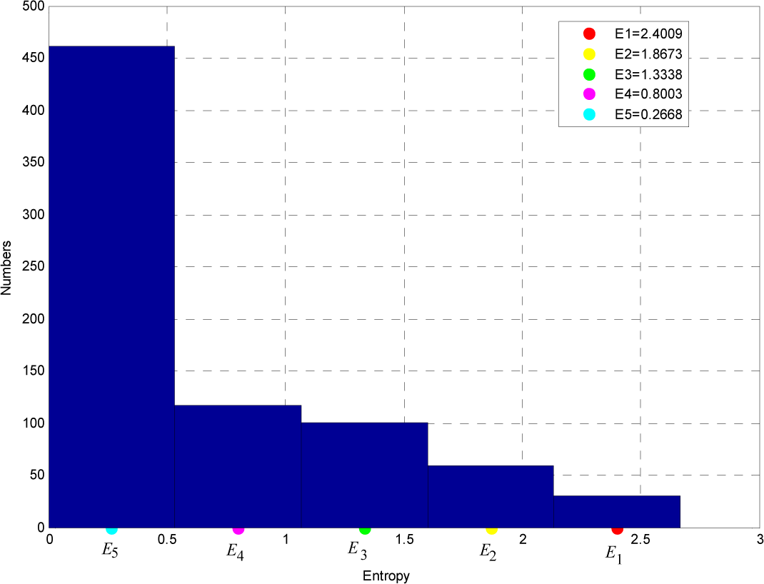
2.3. Entropy Calculation
2.4. Adaptive Measurement Allocation
2.5. Improved CS Reconstruction
3. Experimental Results
4. Conclusions
Acknowledgments
Author Contributions
Conflicts of Interest
References
- Smolic, A.; Kauff, P.; Knorr, S.; Hornung, A.; Kunter, M.; Muller, M.; Lang, M. Three-dimensional video postproduction and processing. Proc. IEEE 2011, 99, 607–625. [Google Scholar]
- Fehn, C.; de la Barré, R.; Pastoor, S. Interactive 3-DTV-Concepts and key technologies. Proc. IEEE 2006, 94, 524–538. [Google Scholar]
- Tanimoto, M. Overview of free viewpoint television. Signal Process. Image Commun. 2006, 21, 454–461. [Google Scholar]
- Vetro, A.; Wiegand, T.; Sullivan, G.J. Overview of the stereo and multiview video coding extensions of the H.264/MPEG-4 AVC standard. Proc. IEEE 2011, 99, 626–642. [Google Scholar]
- Mori, Y.; Fukushima, N.; Yendo, T.; Fujii, T.; Tanimoto, M. View generation with 3D warping using depth information for FTV. Signal Process. Image Commun. 2009, 24, 65–72. [Google Scholar]
- Merkle, P.; Morvan, Y.; Smolic, A.; Farin, D.; Müller, K.; de With, P.H.N.; Wiegand, T. The effect of multiview depth video on multiview rendering. Signal Process. Image Commun. 2009, 24, 73–88. [Google Scholar]
- Candès, E.J.; Wakin, M.B. An introduction to compressive sampling. Signal Process. Mag. 2008, 25, 21–30. [Google Scholar]
- Candès, E.J.; Romberg, J.; Tao, T. Stable signal recovery from incomplete and inaccurate Measurements. Commun. Pure Appl. Math. 2006, 59, 1207–1223. [Google Scholar]
- Gan, L. Block compressed sensing of natural images, Proceedings of the 15th International Conference on Digital Signal Processing, Cardiff, UK, 1–4 July 2007; pp. 403–406.
- Zhang, Y.; Mei, S.; Chen, Q.; Chen, Z. A novel image/video coding method based on compressed sensing theory, Proceedings of the IEEE International Conference on Acoustics, Speech and Signal Processing, Las Vegas, NV, USA, 31 March–4 April 2008; pp. 1361–1364.
- Sarkis, M.; Diepold, K. Depth map compression via compressed sensing, Proceedings of IEEE International Conference on Image Processing, Cairo, Egypt, 7–10 November 2009; pp. 737–740.
- Lee, S.; Ortega, A. Adaptive compressed sensing for depthmap compression using graph-based transform, Proceedings of IEEE International Conference on Image Processing, Orlando, FL, USA, 30 September–3 October 2012; pp. 929–932.
- Ekmekcioglu, E.; Worrall, S.T.; Kondoz, A.M. Bit-rate adaptive downsampling for the coding of multi-view video with depth information, Proceedings of the 3DTV Conference: The True Vision-Capture, Transmission and Display of 3D Video, Istanbul, Turkey, 28–30 May 2008; pp. 137–140.
- Compressive Sensing Resources. Available online: http://dsp.rice.edu/cs accessed on 17 December 2014.
- Shannon, C.E. A mathematical theory of communication. Bell Syst. Tech. J. 1948, 27, 379–423. [Google Scholar]


| Sequence | Resolution | View |
|---|---|---|
| Balloons | 1024×768 | 1–3 |
| Kendo | 1024×768 | 1–3 |
| Pantomime | 1280×960 | 37–39 |
| Schemes | Balloons
| Kendo
| Pantomime
| ||||||
|---|---|---|---|---|---|---|---|---|---|
| Ratio (%) | Encoding Time | Decoding Time | Ratio (%) | Encoding Time | Decoding Time | Ratio (%) | Encoding Time | Decoding Time | |
| Uniform | 20 | 0.0619 | 96.5081 | 20 | 0.0622 | 94.2078 | 20 | 0.0928 | 98.8772 |
| 30 | 0.0709 | 99.7691 | 30 | 0.0709 | 98.1991 | 30 | 0.1072 | 101.4328 | |
| 40 | 0.0785 | 101.9015 | 40 | 0.0775 | 102.3725 | 40 | 0.1220 | 103.7480 | |
| 50 | 0.0873 | 105.1227 | 50 | 0.0849 | 107.5151 | 50 | 0.1353 | 106.4147 | |
| 60 | 0.0946 | 108.7454 | 60 | 0.0937 | 112.0063 | 60 | 0.1497 | 108.3903 | |
| 70 | 0.0980 | 110.1820 | 70 | 0.0965 | 115.0535 | 70 | 0.1513 | 111.1087 | |
| Adaptive | 21.24 | 0.1709 | 98.2591 | 21.62 | 0.1710 | 97.6990 | 21.54 | 0.2687 | 100.1813 |
| 26.94 | 0.1739 | 100.7861 | 27.36 | 0.1737 | 99.9364 | 29.76 | 0.2754 | 103.1046 | |
| 32.41 | 0.1772 | 103.5128 | 31.94 | 0.1761 | 103.0040 | 36.49 | 0.2849 | 104.7951 | |
| 41.20 | 0.1798 | 107.2502 | 41.60 | 0.1785 | 108.5315 | 45.2 | 0.2854 | 107.9946 | |
| 61.80 | 0.1844 | 109.7256 | 61.57 | 0.1837 | 112.2063 | 56.36 | 0.2923 | 109.8677 | |
| Sequence | Ratio | PSNR (dB)
| Encoding time (s)
| ||
|---|---|---|---|---|---|
| Traditional | Proposed | Traditional | Proposed | ||
| Kendo | 27.36% | 45.5579 | 43.7066 | 0.9733 | 0.1736 |
| Balloons | 32.41% | 43.0547 | 40.2082 | 0.9713 | 0.1772 |
| Pantomime | 21.54% | 52.9541 | 49.8902 | 1.4823 | 0.2686 |
© 2014 by the authors; licensee MDPI, Basel, Switzerland This article is an open access article distributed under the terms and conditions of the Creative Commons Attribution license (http://creativecommons.org/licenses/by/4.0/).
Share and Cite
Bai, H.; Zhang, M.; Liu, M.; Wang, A.; Zhao, Y. Depth Image Coding Using Entropy-Based Adaptive Measurement Allocation. Entropy 2014, 16, 6590-6601. https://0-doi-org.brum.beds.ac.uk/10.3390/e16126590
Bai H, Zhang M, Liu M, Wang A, Zhao Y. Depth Image Coding Using Entropy-Based Adaptive Measurement Allocation. Entropy. 2014; 16(12):6590-6601. https://0-doi-org.brum.beds.ac.uk/10.3390/e16126590
Chicago/Turabian StyleBai, Huihui, Mengmeng Zhang, Meiqin Liu, Anhong Wang, and Yao Zhao. 2014. "Depth Image Coding Using Entropy-Based Adaptive Measurement Allocation" Entropy 16, no. 12: 6590-6601. https://0-doi-org.brum.beds.ac.uk/10.3390/e16126590