
Comparison Based on Exergetic Analyses of Two Hot Air Engines: A Gamma Type Stirling Engine and an Open Joule Cycle Ericsson Engine

Abstract
:1. Introduction
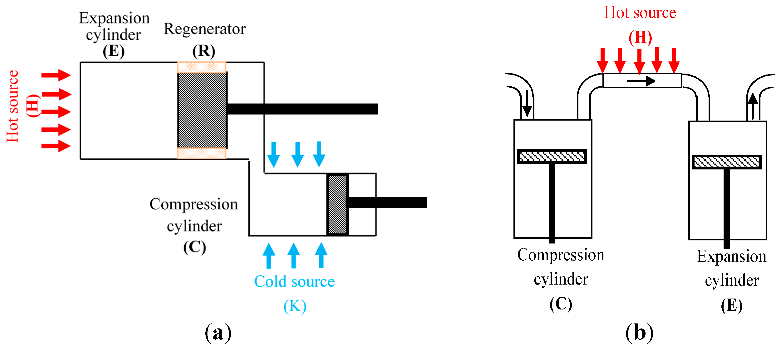
2. Configurations of the Gamma Type Stirling Engine and the Open Cycle Ericsson Engines
2.1. Geometries and Working Conditions


| Engine | Stirling | Ericsson |
| Thermodynamic cycle | closed | open |
| Number of cycles per crankshaft revolution | 1 | 1 |
| Working fluid | air | air |
| Expansion cylinder swept volume | 520 cm3 | 160 cm3 |
| Compression cylinder swept volume | 360 cm3 | 220 cm3 |
| Hot source | expansion cylinder wall | internal tube wall |
| Cold source | compression cylinder wall | atmosphere |
| Regenerator | stainless steel with 85% porosity | - |
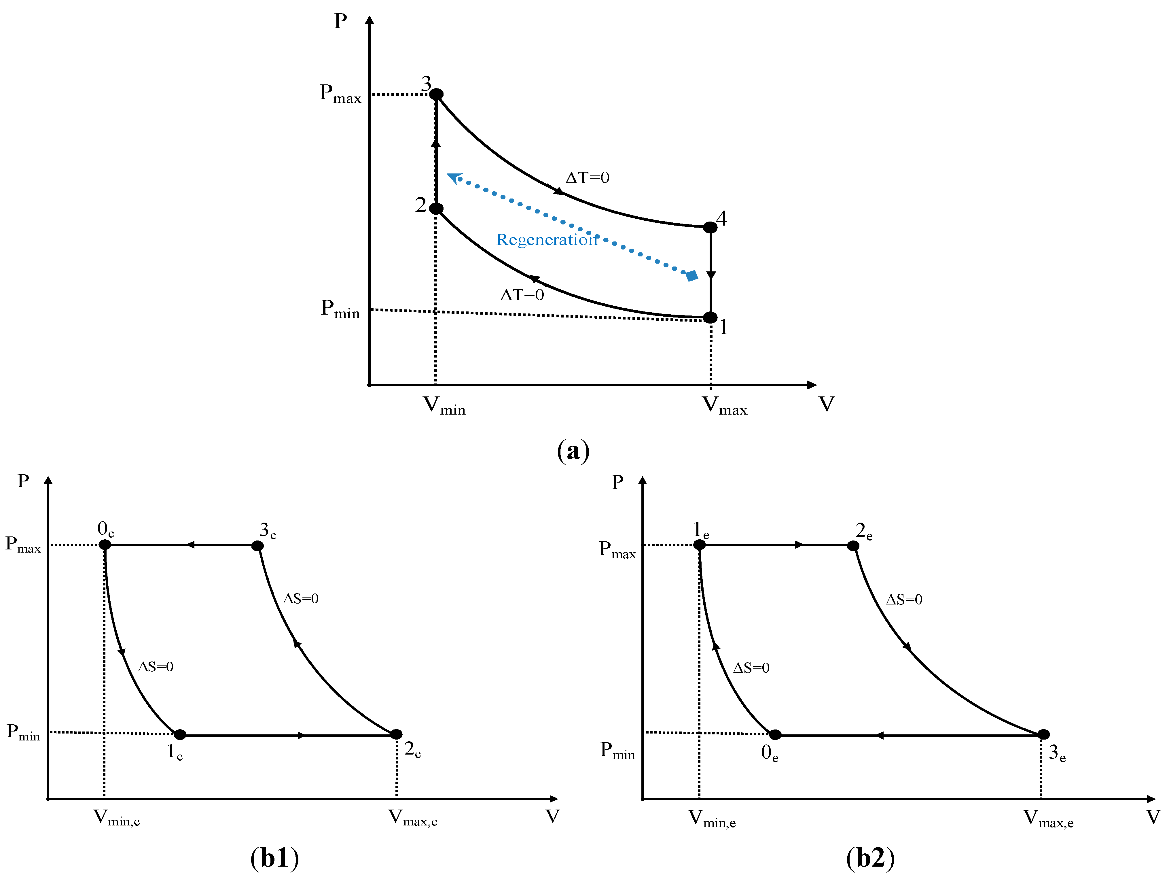
2.2. Thermodynamic Cycles

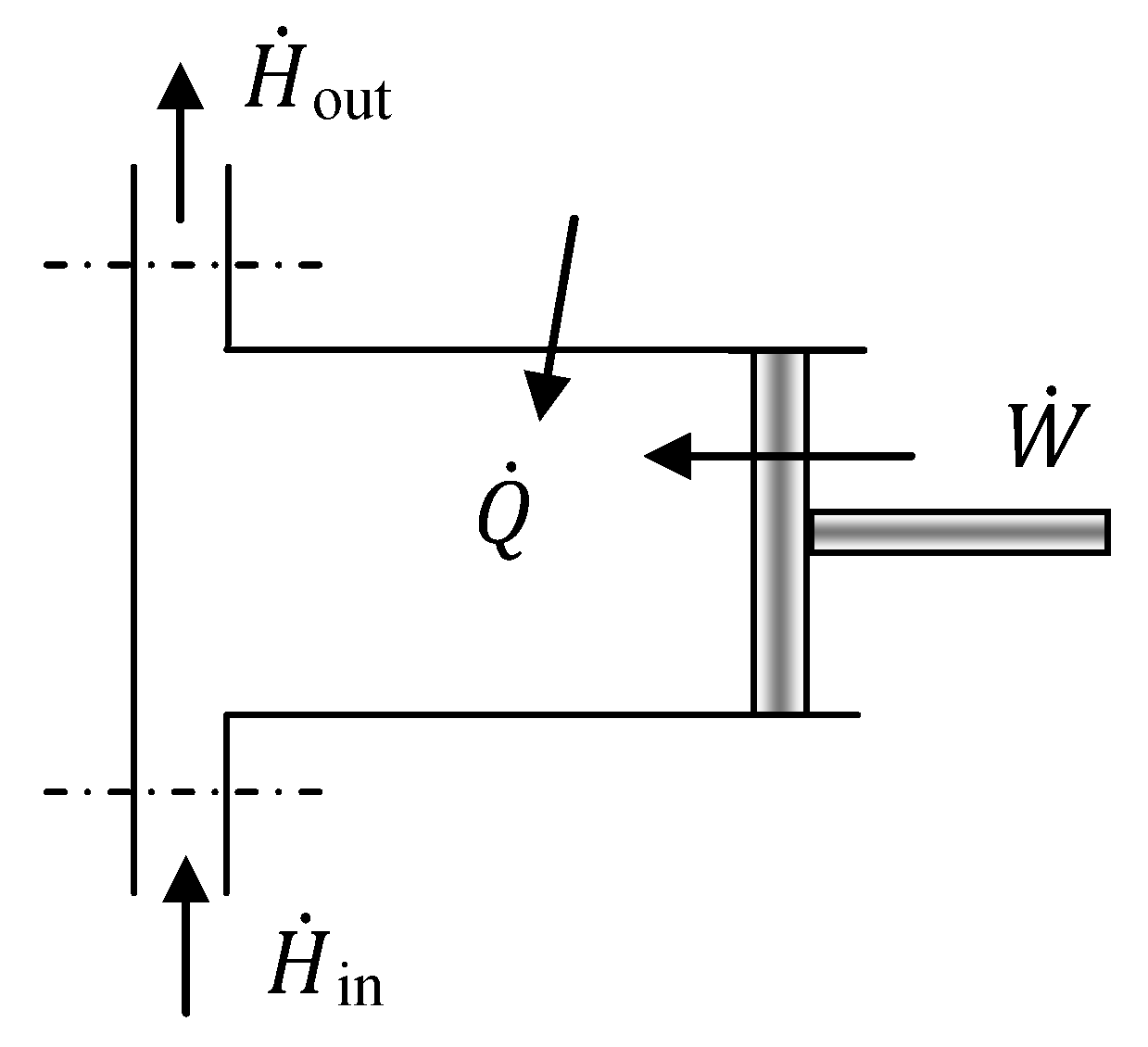
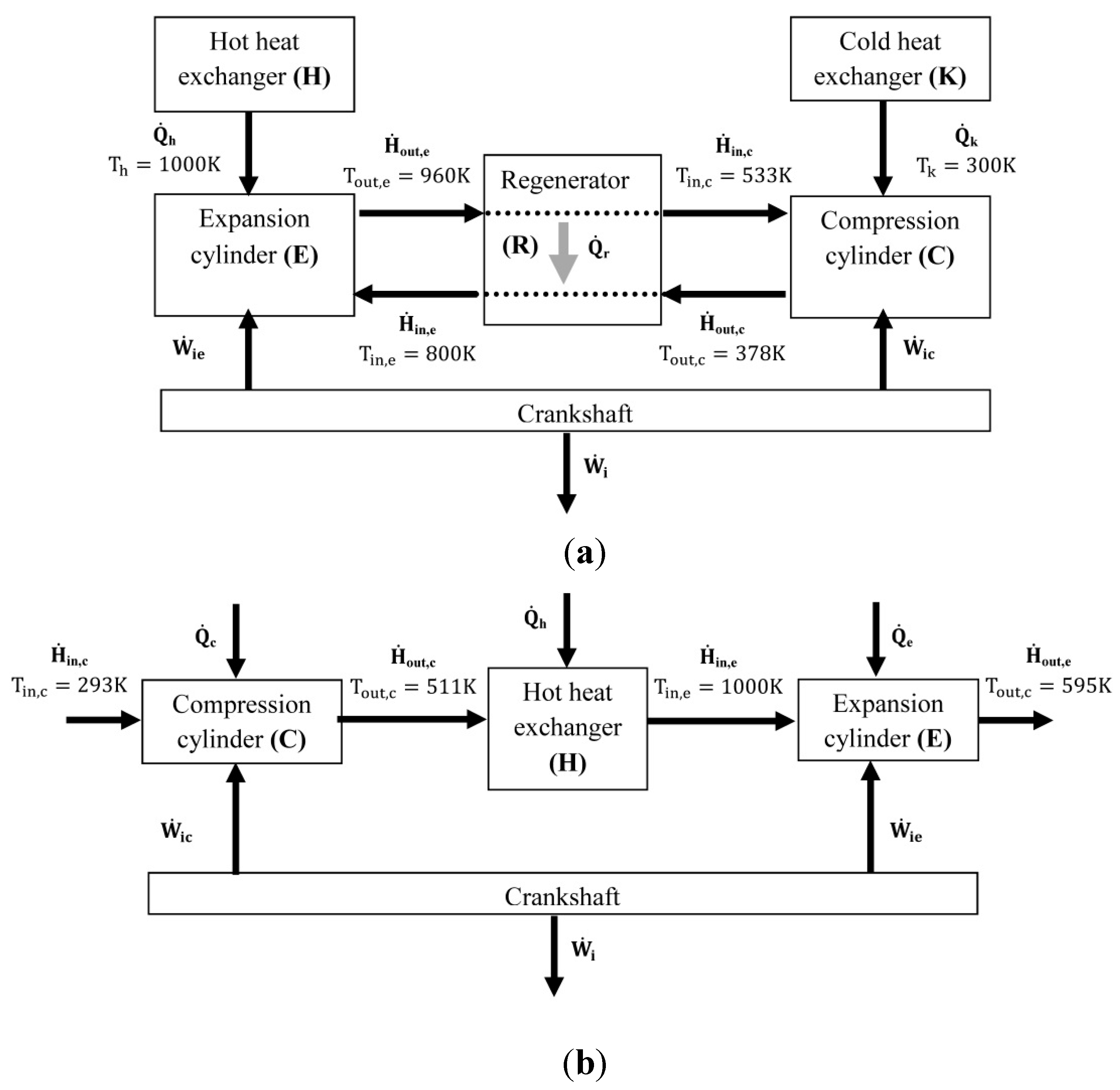
3. Modelling of the Hot Air Engines
3.1. Energy Balance on the Hot Air Engines


3.2. Exergy Balance on the Hot Air Engines
| Stirling engine | Ericsson engine | |||
|---|---|---|---|---|
| (C) | (a) | (d) | ||
| (E) | (b) | (e) | ||
| (R) | (c) | - | ||
3.3. Performances of the Hot Air Engines
| Stirling | Ericsson | |||
|---|---|---|---|---|
| (C) | (a) | (d) | ||
| (E) | (b) | (e) | ||
| (R) | (c) | - | ||
4. Results and Discussion
4.1. Working Conditions of the Stirling and Ericsson Engines
| working pressure | 7 bar |
| hot source temperature | 1000 K |
| cold source temperature | 300 K |
| cycle frequency | 10 Hz |
4.2. Performances
| Ericsson | Stirling | |
|---|---|---|
| indicated mean pressure IMP (bar) | 2.19 | 1.69 |
| specific indicated work wi (J/kg) | 180848 | 269565 |
| global thermodynamic efficiency ηth (%) | 28.64% | 37.42% |
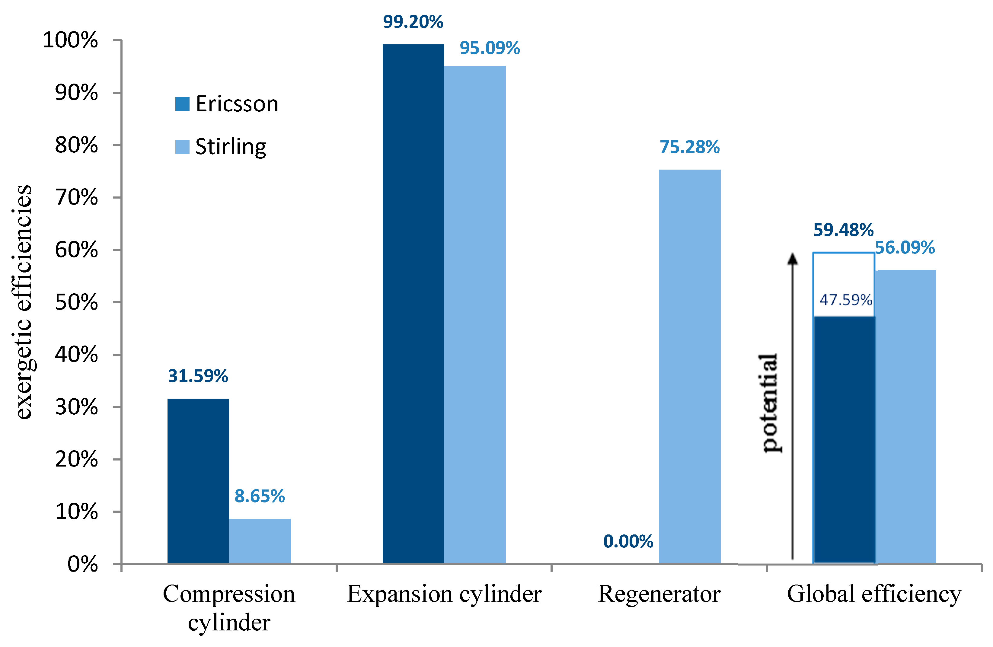
| global exergetic efficiency ηex (%) | 47.59% | 56.09% |
| Ericsson potential exergetic efficiency ηex,pot (%) | 59.48% | - |
4.3. Dimensionless Exergy Fluxes

4.4. Exergetic Efficiencies

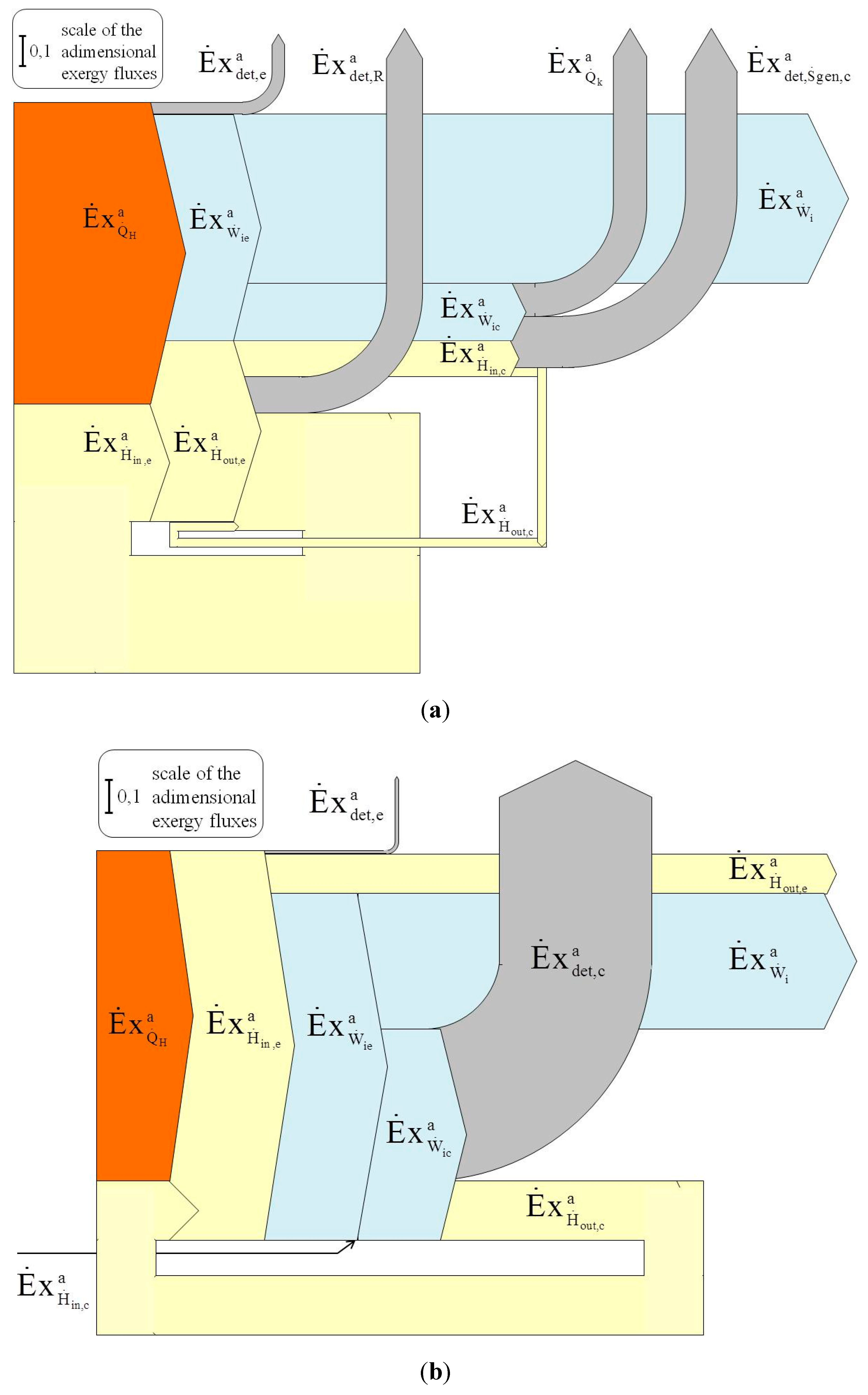
4.5. Sankey Diagrams

5. Conclusions
Acknowledgments
Author Contributions
Conflicts of Interest
Nomenclature
exergy flux (W) | |
total destroyed exergy flux (W) | |
destroyed exergy flux associated to entropy generation (W) | |
| h | specific enthalpy (J/kg) |
total enthalpy flux (W) | |
| IMP | indicated mean pressure (Pa) |
| mair,e | mass of air entering the expansion cylinder during each cycle (kg) |
| P | pressure (Pa) |
| Q | heat exchanged (J) |
heat flux (W) | |
| r | air specific gas constant (J/kg.K) |
| s | specific entropy (J/kg.K) |
flux of generated entropy (W/K) | |
| t | time (s) |
| T | temperature (K) |
| U | internal energy (J) |
| V | volume (m3) |
| Vswept,e | swept volume of the expansion cylinder (m3) |
| W | indicated work (J) |
indicated power (W) | |
| wi | specific indicated work (J/kg) |
Greek letters
| ηex | exergetic efficiency (%) |
| ηth | thermodynamic efficiency (%) |
Subscripts
| a | Ambient |
| c | Compression cylinder |
| e | Expansion cylinder |
| h | hot source or hot temperature heat exchanger |
| i | indicated |
| k | cold source or cold temperature heat exchanger |
| in | Input |
| max | Maximum |
| min | Minimum |
| r | Regenerator |
| ref | Reference |
| out | Output |
| w | wall |
Superscripts
| d | dimensionless |
Abbreviations
| C | compression chamber (Ericsson engine) |
| E | expansion chamber (Ericsson engine) |
| H | heat exchanger in contact with hot source |
| K | heat exchanger in contact with cold source |
| R | regenerator |
References
- Creyx, M.; Delacourt, E.; Morin, C.; Desmet, B.; Peultier, P. Energetic optimization of the performances of a hot air engine for micro-CHP systems working with a Joule or an Ericsson cycle. Energy 2013, 49, 229–239. [Google Scholar] [CrossRef]
- Simader, G.R.; Krawinkler, R.; Trnka, G. Micro CHP Systems: State-of-the-Art; Österreichische Energieagentur–Austrian Energy Agency: Vienna, Austria, 2006. [Google Scholar]
- Angelino, G.; Invernizzi, C. Real gas effects in Stirling engines. In Proceedings of the Energy Conversion Engineering Conference and Exhibit (IECEC) 35th Intersociety, Las Vegas, NV, USA, 24–28 July 2000.
- Costea, M.; Feidt, M. The effect of the overall heat transfer coefficient variation on the optimal distribution of the heat transfer surface conductance or area in a Stirling engine. Energy Convers. Manag. 1998, 39, 1753–1761. [Google Scholar] [CrossRef]
- Parlak, N.; Wagner, A.; Elsner, M.; Soyhan, H.S. Thermodynamic analysis of a gamma type Stirling engine in non-ideal adiabatic conditions. Int. J. Renew. Energy 2009, 34, 266–273. [Google Scholar] [CrossRef]
- Touré, A.; Soubacq, S.; Alaphilippe, M.; Marquet, D.; Stouffs, P. Design, experimental setup and preliminary testing results of a small Joule cycle Ericsson engine prototype. In Proceedings of the International Stirling Forum, ISF 2008, Osnabrück, Germany, 23–23 September 2008.
- Brzeski, L.; Kazimierski, Z. Experimental investigations of the externally heated valve engine model. Proc. Inst. Mech. Eng. A 2001, 215, 486–494. [Google Scholar] [CrossRef]
- Wu, D.; Roskilly, A.P. Design and parametric analysis of linear Joule-cycle engine with out-of-cylinder combustion. In Proceedings of the 6th International Conference on Applied Energy, ICAE 2014, Taipei, Taiwan, 30 May–2 June 2014.
- Wojewoda, J.; Kazimierski, Z. Numerical model and investigations of the externally heated valve Joule engine. Energy 2010, 35, 2099–2108. [Google Scholar] [CrossRef]
- Moss, R.W.; Roskilly, A.P.; Nanda, S.K. Reciprocating Joule-cycle engine for domestic CHP systems. Appl. Energy 2005, 80, 169–185. [Google Scholar] [CrossRef]
- Bell, M.A.; Partridge, T. Thermodynamic design of a reciprocating Joule cycle engine. Proc. Inst. Mech. Eng. A 2003, 217, 239–246. [Google Scholar] [CrossRef]
- Thombare, D.G.; Verma, S.K. Technological development in the Stirling cycle engines. Int. J. Renew. Sust. Energy 2008, 12, 1–38. [Google Scholar] [CrossRef]
- Berchowitz, D.M. Free-Piston Rankine Compression and Stirling Cycle Machines for Domestic Refrigeration. In Proceedings of the Greenpeace Ozone Safe Conference, Washington, VA, USA, 18–19 October 1993.
- Urieli, I.; Berchowitz, D.M. Stirling Cycle Engine Analysis; Taylor & Francis: London, UK, 1984. [Google Scholar]
- Bonnet, S.; Alaphilippe, M.; Stouffs, P. Energy, exergy and cost analysis of a micro-cogeneration system based on an Ericsson engine. Int. J. Therm. Sci. 2005, 44, 1161–1168. [Google Scholar] [CrossRef]
- Martaj, N.; Grosu, L. Exergetical analysis and design optimisation of the Stirling engine. Int. J. Exergy 2006, 3, 45–67. [Google Scholar] [CrossRef]
- Martaj, N.; Grosu, L.; Rochelle, P. Thermodynamic Study of a Low Temperature Difference Stirling Engine at Steady State Operation. Int. J. Thermodyn. 2007, 10, 165–176. [Google Scholar]
- Hachem, H.; Gheith, R.; Aloui, F.; Ben Nasrallah, S.; Dincer, I. Energetic and Exergetic Performance Assessments of an Experimental Beta Type Stirling Engine. In Proceedings of the 7th International Ege Energy Symposium & Exhibition (IEESE 2014), Usak, Turkey, 18–20 June 2014.
- Saneipoor, P.; Naterer, G.F.; Dincer, I. Heat recovery from a cement plant with a Marnoch Heat Engine. Appl. Therm. Eng. 2011, 31, 1734–1743. [Google Scholar] [CrossRef]
- Saneipoor, P.; Dincer, I.; Naterer, G.F. Thermodynamic analysis of a new Marnoch Heat Engine. Appl. Therm. Eng. 2013, 52, 516–526. [Google Scholar] [CrossRef]
- Saneipoor, P.; Naterer, G.F.; Dincer, I. Power generation from a new air-based Marnoch heat engine. Energy 2011, 36, 6879–6889. [Google Scholar] [CrossRef]
- Stouffs, P. Does the Ericsson engine deserves more consideration than the Stirling engine? In Proceedings of the European Stirling Forum, Osnabrück, Germany, 18–19 September 2002.
- Gheith, R.; Aloui, F.; Tazerout, M.; Ben Nasrallah, S. Experimental investigations of a Gamma Stirling engine. Energy Res. 2012, 36, 1175–1182. [Google Scholar] [CrossRef]
- Gheith, R.; Aloui, F.; Ben Nasrallah, S. Study of regenerator constituting material influence on a Gamma type Stirling engine. J. Mech. Sci. Technol. 2012, 26, 1251–1255. [Google Scholar] [CrossRef]
- Gheith, R.; Aloui, F.; Ben Nasrallah, S. Determination of adequate regenerator for a Gamma-type Stirling engine. Appl. Energy 2015, 139, 272–280. [Google Scholar] [CrossRef]
- Gheith, R.; Aloui, F.; Ben Nasrallah, S. Optimization of Stirling engine performance based on an experimental design approach. Int. J. Energy Res. 2013, 37, 1519–1528. [Google Scholar] [CrossRef]
- Hachem, H.; Gheith, R.; Aloui, F.; Ben Nasrallah, S. Global numerical characterization of a γ-Stirling engine considering losses and interaction between functioning parameters. Energy Convers. Manag. 2015, 96, 532–543. [Google Scholar] [CrossRef]
- Creyx, M.; Delacourt, E.; Lippert, M.; Morin, C.; Desmet, B. Modélisation des performances d’un moteur Ericsson à cycle de Joule ouvert. Revista Termotehnica 2014, 1, 64–70. (In French) [Google Scholar]
- Moran, M.J.; Shapiro, H.N. Fundamentals of Engineering Thermodynamics; Wiley: Chichester, UK, 2006. [Google Scholar]
- Dincer, I.; Rosen, M.A. Exergy: Energy, Environment and Sustainable Development; Elsevier: Amsterdam, The Netherlands, 2007. [Google Scholar]
© 2015 by the authors; licensee MDPI, Basel, Switzerland. This article is an open access article distributed under the terms and conditions of the Creative Commons Attribution license (http://creativecommons.org/licenses/by/4.0/).
Share and Cite
Hachem, H.; Creyx, M.; Gheith, R.; Delacourt, E.; Morin, C.; Aloui, F.; Nasrallah, S.B. Comparison Based on Exergetic Analyses of Two Hot Air Engines: A Gamma Type Stirling Engine and an Open Joule Cycle Ericsson Engine. Entropy 2015, 17, 7331-7348. https://0-doi-org.brum.beds.ac.uk/10.3390/e17117331
Hachem H, Creyx M, Gheith R, Delacourt E, Morin C, Aloui F, Nasrallah SB. Comparison Based on Exergetic Analyses of Two Hot Air Engines: A Gamma Type Stirling Engine and an Open Joule Cycle Ericsson Engine. Entropy. 2015; 17(11):7331-7348. https://0-doi-org.brum.beds.ac.uk/10.3390/e17117331
Chicago/Turabian StyleHachem, Houda, Marie Creyx, Ramla Gheith, Eric Delacourt, Céline Morin, Fethi Aloui, and Sassi Ben Nasrallah. 2015. "Comparison Based on Exergetic Analyses of Two Hot Air Engines: A Gamma Type Stirling Engine and an Open Joule Cycle Ericsson Engine" Entropy 17, no. 11: 7331-7348. https://0-doi-org.brum.beds.ac.uk/10.3390/e17117331