Optimal Design of Magnetohydrodynamic Mixed Convection Flow in a Vertical Channel with Slip Boundary Conditions and Thermal Radiation Effects by Using an Entropy Generation Minimization Method

Abstract
:1. Introduction
2. Governing Equations
3. Results and Discussion
4. Conclusions
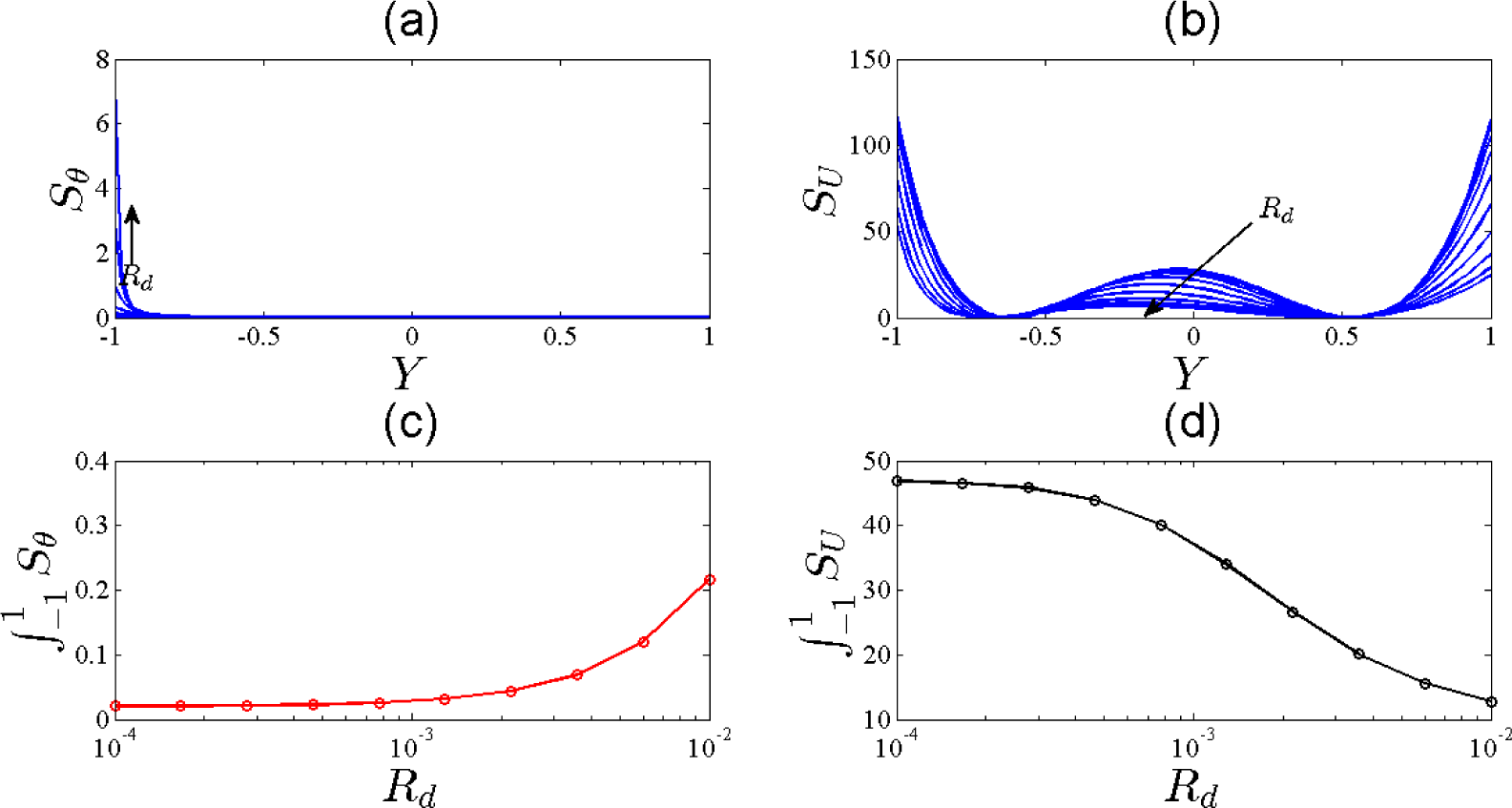
- By increasing Rd, the heat transfer part of the entropy increases dramatically while the viscous part of the entropy decreases.
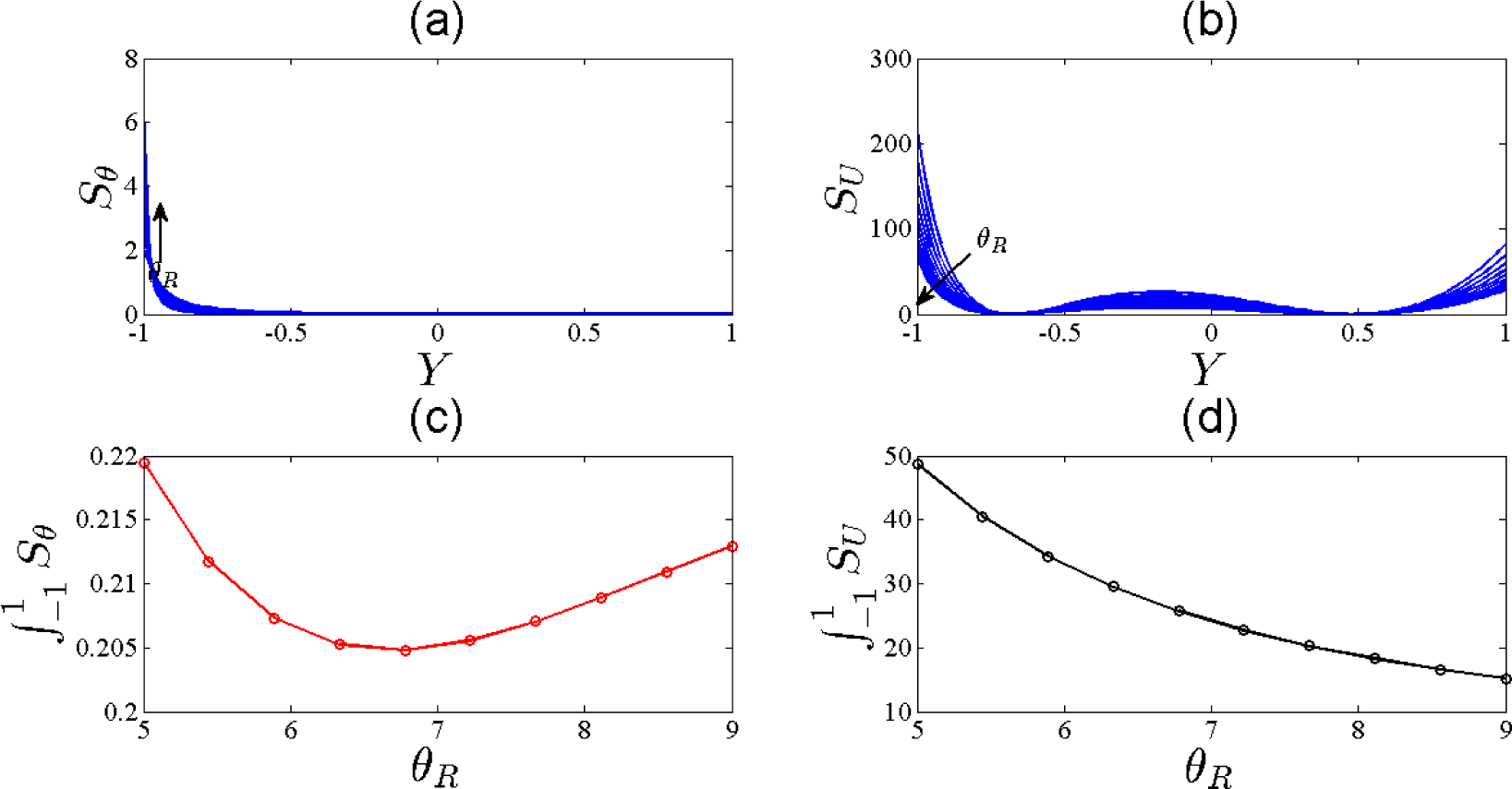
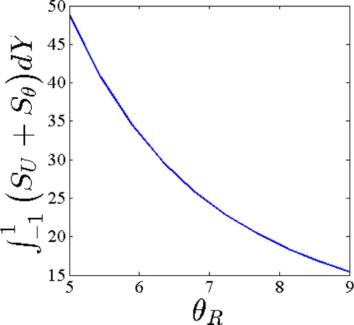
- By increasing θR, the total heat transfer entropy generation has a minimum at θR = 6.6. Also the total viscous entropy generation decreases as θR increases.
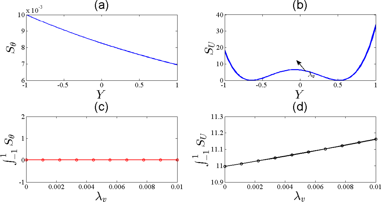
- Lower velocity slip, Grashof number to Reynolds number ratio are better for maximize the exergy of the system.
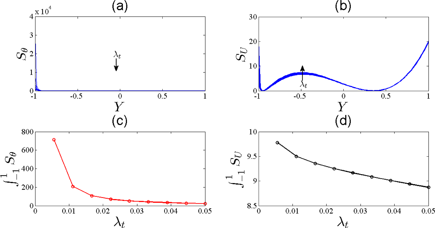
- Higher temperature slip is better for maximizing the exergy of the system.
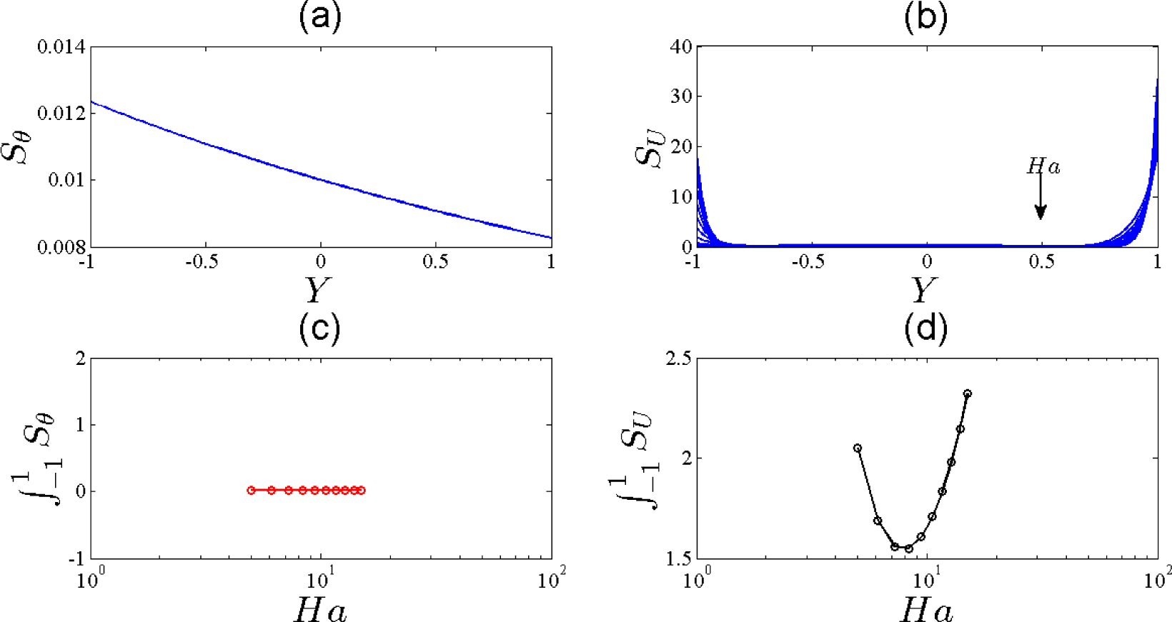
- The optimum Hartmann number is about 8.
Acknowledgments
Author Contributions
Conflicts of Interest
References
- Barletta, A. Analysis of combine forced and free flow in a vertical channel with viscous dissipation and isothermal-isoflux boundary conditions. J. Heat Transf. 1999, 121, 349–356. [Google Scholar]
- Barletta, A. Fully developed mixed convection and flow reversal in a vertical rectangular duct with uniform wall heat flux. Int. J. Heat Mass Transf. 2002, 45, 641–654. [Google Scholar]
- Boulama, K.; Galanis, N. Analytical solution for fully developed mixed convection between parallel vertical plates with heat and mass transfer. J. Heat Transf. 2004, 126, 381–388. [Google Scholar]
- Modest, M.F. Radiative Heat Transfer, 2nd ed; Academic Press: New York, NY, USA, 2003. [Google Scholar]
- Baytaş, A.C.; Liaqat, A.; Groşan, T.; Pop, I. Conjugate natural convection in a square porous cavity. Heat Mass Transf. 2001, 37, 467–473. [Google Scholar]
- Hadjadj, A.; Ben-Nasr, O.; Shadloo, M.S.; Chaudhuri, A. Effect of wall temperature in supersonic turbulent boundary layers: A numerical study. Int. J. Heat Mass Transf. 2015, 81, 426–438. [Google Scholar]
- Kandlikar, S.G. High flux heat removal with microchannels—A roadmap of challenges and opportunities. Heat Transf. Eng. 2005, 26, 5–14. [Google Scholar]
- Zhao, C.Y.; Lu, T.J. Analysis of microchannel heat sinks for electronics cooling. Int. J. Heat Mass Transf. 2002, 45, 4857–4869. [Google Scholar]
- Liu, D.; Garimella, S.V. Investigation of liquid flow in microchannels. J. Thermophys. Heat Transf. 2004, 18, 65–72. [Google Scholar]
- Judy, J.; Maynes, D.; Webb, B.W. Characterization of frictional pressure drop for liquid flows through microchannels. Int. J. Heat Mass Transf. 2002, 45, 3477–3489. [Google Scholar]
- Abdollahzadeh Jamalabadi, M.Y. Effect of fuel inject angle on non-premixed combustion of air/methane mixtures in vertical cylinder. Int. J. Multidiscip. Res. Dev. 2014, 1. Available online: http://allsubjectjournal.com/vol1/issue5/PartA/pdf/13.1.pdf accessed on 11 February 2015.
- Kandlikar, S.G.; Schmit, D.; Carrano, A.L.; Taylor, J.B. Characterization of surface roughness effects on pressure drop in microchannels. Phys. Fluids. 2005, 17. [Google Scholar] [CrossRef]
- Abdollahzadeh Jamalabadi, M.Y.; Ghasemi, M.; Hamedi, M.H. Two-dimensional simulation of thermal loading with horizontal heat sources. Proc. Inst. Mech. Eng. C 2012, 226, 1302–1308. [Google Scholar]
- Abdollahzadeh Jamalabadi, M.Y.; Ghasemi, M.; Hamedi, M.H. Numerical investigation of thermal radiation effects on open cavity with discrete heat sources. Int. J. Numer. Methods Heat Fluid Flow 2013, 23, 649–661. [Google Scholar]
- Abdollahzadeh Jamalabadi, M.Y. Experimental investigation of thermal loading of a horizontal thin plate using infrared camera. J. King Saud Univ. Eng. Sci. 2014, 26, 159–167. [Google Scholar]
- Abdollahzadeh Jamalabadi, M.Y.; Park, J.H. Thermal radiation, joule heating, and viscous dissipation effects on MHD forced convection flow with uniform surface temperature. Open J. Fluid Dyn. 2014, 4, 125–132. [Google Scholar]
- Abdollahzadeh Jamalabadi, M.Y. Analytical study of Magnetohydrodynamic propulsion stability. J. Mar. Sci. Appl. 2014, 13, 281–290. [Google Scholar]
- Shahidian, A.; Ghassemi, M.; Khorasanizade, S.; Abdollahzade, M.; Ahmadi, G. Flow Analysis of non-Newtonian blood in a magnetohydrodynamic pump. IEEE Trans. Magn. 2009, 45, 2667–2670. [Google Scholar]
- Abdollahzadeh Jamalabadi, M.Y.; Park, J.H. Electro-magnetic ship propulsion stability under gusts. Int. J. Sci. Basic Appl. Res. 2014, 1, 421–427. [Google Scholar]
- Abdollahzadeh Jamalabadi, M.Y.; Park, J.H.; Lee, C.Y. Thermal radiation effects on the onset of unsteadiness of fluid flow in vertical microchannel filled with highly absorbing medium. Therm. Sci. 2014. [Google Scholar] [CrossRef]
- Field, J.E.; Hahn, K.H.; Harris, S.E. Observation of electromagnetically induced transparency in collisionally broadened lead vapor. Phys. Rev. Lett. 1991, 67, 3062–3065. [Google Scholar]
- Lemoff, B.E.; Yin, G.Y.; Gordon, C.L., III; Barty, C.P.J.; Harris, S.E. Demonstration of a 10-Hz femtosecond-pulse-driven XUV laser at 41.8 nm in Xe IX. Phys. Rev. Lett. 1995, 74, 1574–1577. [Google Scholar]
- Kadowaki, M.; Yoshizawa, H.; Mori, S.; Suzuki, M. Plasma CVD on the inner surface of a microchannel. Thin Solid Films 2006, 506, 123–127. [Google Scholar]
- Kumar, V.; Paraschivoiu, M.; Nigam, K.D.P. Single-phase fluid flow and mixing in microchannels. Chem. Eng. Sci. 2011, 66, 1329–1373. [Google Scholar]
- Aghanajafi, C.; Vandadi, V.; Shahnazari, M.R. Investigation of convection and radiation heat transfer in rhombus microchannels. Int. J. Res. Rev. App. Sci. 2010, 3, 167–176. [Google Scholar]
- Leibrandt, D.R.; Drake, R.P.; Reighard, A.B. A validation test of the flux-limited diffusion approximation for radiation hydrodynamics. Astrophys. J. 2005, 626, 616–625. [Google Scholar]
- Karniadakis, G.; Beskok, A.; Aluru, N. Microflows and Nanoflows: Fundamentals and Simulation; Springer: New York, NY, USA, 2003. [Google Scholar]
- Ulmanella, U.; Ho, C.M. Molecular effects on boundary condition in micro/nanoliquid flows. Phys. Fluids. 2008, 20. [Google Scholar] [CrossRef]
- Bocquet, L.; Barrat, J.-L. Flow boundary conditions from nano- to micro-scales. Soft Matt 2007, 3, 685–693. [Google Scholar]
- Horvath, J.A.; Webb, R.N. Experimental study of radiation absorption by microchannels of varying aspect ratios. Solar Energ. 2011, 85, 1035–1040. [Google Scholar]
- Hossain, M.S.; Saidur, R.; Fayaz, H.; Rahim, N.A.; Islam, M.R.; Ahamed, J.U.; Rahman, M.M. Review on solar water heater collector and thermal energy performance of circulating pipe. Renew. Sustain. Energ. Rev. 2011, 15, 3801–3812. [Google Scholar]
- Taylor, R.A.; Phelan, P.E.; Otanicar, T.P.; Adrian, R.; Prasher, R. Nanofluid optical property characterization: towards efficient direct absorption solar collectors. Nanoscale Res. Lett. 2011, 6. [Google Scholar] [CrossRef]
- Thompson, P.A.; Troian, S.M. A general boundary condition for liquid flow at solid surfaces. Nature 1997, 389, 360–362. [Google Scholar]
- Barrat, J.-L.; Bocquet, L. Large slip effect at a nonwetting fluid-solid interface. Phys. Rev. Lett. 1999, 82, 4671–4674. [Google Scholar]
- Cieplak, M.; Koplik, J.; Banavar, J.R. Boundary conditions at a fluid-solid surface. Phys. Rev. Lett. 2001, 86, 803–806. [Google Scholar]
- Guasto, J.S.; Breuer, K.S. High-speed quantum dot tracking and velocimetry using evanescent wave illumination. Exp. Fluids. 2009, 47, 1059–1066. [Google Scholar]
- Bouzigues, C.I.; Tabeling, P.; Bocquet, L. Nanofluidics in the Debye layer at hydrophilic and hydrophobic surfaces. Phys. Rev. Lett. 2008, 101. [Google Scholar] [CrossRef]
- Huang, P.; Guasto, J.S.; Breuer, K.S. Direct measurement of slip velocities using three-dimensional total internal reflection velocimetry. J. Fluid Mech. 2006, 566, 447–464. [Google Scholar]
- Huang, P.; Breuer, K.S. Direct measurement of slip length in electrolyte solutions. Phys. Fluids. 2007, 19. [Google Scholar] [CrossRef]
- Bejan, A. Second-law analysis in heat transfer and thermal design. Adv. Heat Transfer 1982, 15, 1–58. [Google Scholar]
- Bejan, A. Entropy Generation Minimization; CRC: Boca Raton, FL, USA, 1996. [Google Scholar]
- Makinde, O.D.; Eegunjobi, A.S. Entropy generation in a couple stress fluid flow through a vertical channel filled with saturated porous media. Entropy 2013, 15, 4589–4606. [Google Scholar]
- Eegunjobi, A.S.; Makinde, O.D. Combined effect of buoyancy force and Navier slip on entropy generation in a vertical porous channel. Entropy 2012, 14, 1028–1044. [Google Scholar]
- Ozkol, I.; Komurgoz, G.; Arikoglu, A. Entropy generation in the laminar natural convection from a constant temperature vertical plate in an infinite fluid. J. Power Energ 2007, 221, 609–616. [Google Scholar]
- Mahmud, S.; Fraser, R.A. Mixed convection-radiation interaction in a vertical porous channel: Entropy generation. Energy 2003, 28, 1557–1577. [Google Scholar]
- Tasnim, S.H.; Shohel, M.; Mamum, M.A.H. Entropy generation in a porous channel with hydromagetic effect. Exergy: Int. J. 2002, 2, 300–308. [Google Scholar]
- Chauhan, D.S.; Kumar, V. Heat transfer and entropy generation during compressible fluid flow in a channel partially filled with porous medium. Int. J. Energ. Tech. 2011. Available online: http://www.as-se.org/ijet/paperInfo.aspx?ID=19088 accessed on 13 February 2015.
- Chen, S.; Liu, Z.H.; Bao, S.; Zheng, C.G. Natural convection and entropy generation in a vertically concentric annular space. Int. J. Therm. Sci. 2010, 49, 2439–2452. [Google Scholar]
- Chen, S. Entropy generation of double-diffusive convection in the presence of rotation. Appl. Math. Comput. 2011, 217, 8575–8597. [Google Scholar]
- Bianco, V.; Manca, O.; Nardini, S. Second law analysis of Al2O3-water nanofluid turbulent forced convection in a circular cross section tube with constant wall temperature. Adv. Mech. Eng. 2013, 2013. [Google Scholar] [CrossRef]
- Bianco, V.; Manca, O.; Nardini, S. Entropy generation analysis of turbulent convection flow of Al2O3–water nanofluid in a circular tube subjected to constant wall heat flux. Energ. Conver. Manage. 2014, 77, 306–314. [Google Scholar]
- Hairer, E.; Nørsett, S.; Wanner, G. Solving Ordinary Differential Equations I: Nonstiff Problems; Springer: Berlin/Heidelberg, Germany, 1993. [Google Scholar]
- Press, W.H.; Teukolsky, S.A.; Vetterling, W.T.; Flannery, B.P. Numerical Recipes: The Art of Scientific Computing; Cambridge University Press: New York, NY, USA, 2007. [Google Scholar]


© 2015 by the authors; licensee MDPI, Basel, Switzerland This article is an open access article distributed under the terms and conditions of the Creative Commons Attribution license (http://creativecommons.org/licenses/by/4.0/).
Share and Cite
Abdollahzadeh Jamalabadi, M.Y.; Park, J.H.; Lee, C.Y. Optimal Design of Magnetohydrodynamic Mixed Convection Flow in a Vertical Channel with Slip Boundary Conditions and Thermal Radiation Effects by Using an Entropy Generation Minimization Method. Entropy 2015, 17, 866-881. https://0-doi-org.brum.beds.ac.uk/10.3390/e17020866
Abdollahzadeh Jamalabadi MY, Park JH, Lee CY. Optimal Design of Magnetohydrodynamic Mixed Convection Flow in a Vertical Channel with Slip Boundary Conditions and Thermal Radiation Effects by Using an Entropy Generation Minimization Method. Entropy. 2015; 17(2):866-881. https://0-doi-org.brum.beds.ac.uk/10.3390/e17020866
Chicago/Turabian StyleAbdollahzadeh Jamalabadi, Mohamad Yaghoub, Jae Hyun Park, and Chang Yeop Lee. 2015. "Optimal Design of Magnetohydrodynamic Mixed Convection Flow in a Vertical Channel with Slip Boundary Conditions and Thermal Radiation Effects by Using an Entropy Generation Minimization Method" Entropy 17, no. 2: 866-881. https://0-doi-org.brum.beds.ac.uk/10.3390/e17020866