Article

Energetic and Exergetic Analysis of an Ejector-Expansion Refrigeration Cycle Using the Working Fluid R32

Institute of Architecture and Civil Engineering, North China University of Science and Technology, Tangshan 063009, China
*
Author to whom correspondence should be addressed.
Entropy 2015, 17(7), 4744-4761; https://0-doi-org.brum.beds.ac.uk/10.3390/e17074744
Submission received: 23 May 2015 / Revised: 22 June 2015 / Accepted: 30 June 2015 / Published: 6 July 2015

Abstract

:
The performance characteristics of an ejector-expansion refrigeration cycle (EEC) using R32 have been investigated in comparison with that using R134a. The coefficient of performance (COP), the exergy destruction, the exergy efficiency and the suction nozzle pressure drop (SNPD) are discussed. The results show that the application of an ejector instead of a throttle valve in R32 cycle decreases the cycle’s total exergy destruction by 8.84%–15.84% in comparison with the basic cycle (BC). The R32 EEC provides 5.22%–13.77% COP improvement and 5.13%–13.83% exergy efficiency improvement respectively over the BC for the given ranges of evaporating and condensing temperatures. There exists an optimum suction nozzle pressure drop (SNPD) which gives a maximum system COP and volumetric cooling capacity (VCC) under a specified condition. The value of the optimum SNPD mainly depends on the efficiencies of the ejector components, but is virtually independent of evaporating temperature and condensing temperature. In addition, the improvement of the component efficiency, especially the efficiencies of diffusion nozzle and the motive nozzle, can enhance the EEC performance.

1. Introduction

The throttling loss in the expansion device is one of the major thermodynamic losses of a conventional vapor compression refrigeration cycle. It is represented by kinetic energy dissipated by friction while refrigerant is expanded isenthalpically through the throttle valve. Replacing the throttle valve with a two-phase ejector is an effective measure to reduce the throttling irreversibilities. Through the action of the ejector, the compressor inlet pressure is increased and thus higher than what it would have been in a basic cycle (BC). Consequently, the compressor requires less power, improving the performance of the system.
Most recent investigations have been concentrated on transcritical R744 ejector-expansion refrigeration cycles (EECs) because of the large improvement potential owing to the high throttling loss [111]. Subcritical EECs have received much less attention because these cycles offer relatively lower improvement potential through the ejector action. However, it is still worth investigating these subcritical cycles with a two-phase ejector to improve the cycle performance. Kornhauser [12] developed a one-dimensional iterative model on the two-phase EEC, and reported that the theoretical coefficient of performance (COP) improvements of 13%, 21%, 20%, and 12% over the basic cycle for R11, R12, R22, and ammonia, respectively. Domanski [13] found that the use of an ejector provided 10%–30% theoretical COP improvement for refrigerants, including R12, R22, R32, R134a, propane, isobutane and ammonia. Nehdi et al. [14] numerically discovered that replacing the throttle valve with a two-phase ejector improved COP up to 22% in a vapor compression system using R141b as refrigerant. Bilir and Ersoy [15] found theoretically that an EEC using R134a could provide 22.3% COP improvement compared with that of basic cycle. Disawas and Wongwises [16] and Wongwises and Disawas [17] presented experimental results comparing an EEC to the basic cycle using R134a as the refrigerant. In their cycle, there was no throttle valve upstream of the evaporator so that the evaporator is flooded with the refrigerant. The COP improvement of about 5% was obtained. Pottker and Hrnjak [18] experimentally tested an R410A EEC and reported improvements from 8.2% to 14.8% over the basic system. Li et al. [19] investigated the performance of an EEC using R1234yf and R134a and found that the R1234yf EEC has lower COP and volumetric cooling capacity (VCC), but it offers greater COP and VCC improvement potential compared with that of R134a EEC. Bilir et al. [20] experimentally found that the use of an ejector in place of the throttle valve in a R134a refrigeration cycle will improve the COP and exergy efficiency by 7.34%–12.87% and 6.6%–11.24%, respectively, under the same external operating conditions. Lawrence and Elbel [21] conducted an experimental investigation of EEC that can provide multiple evaporation temperatures, and found that the cycle showed maximum COP improvements of 12% with R1234yf and 8% with R134a compared with a two evaporation temperatures basic cycle. However, the cycle showed maximum COP improvements of only 6% with R1234yf and 5% with R134a compared with a single evaporation temperature basic cycle.
Owing to the limited number of studies about subcritical EECs, there is opportunity to investigate the performance of these cycles. Furthermore, R32 is a potential alternative refrigerant owing to the virtues of zero ozone depleting potential (ODP), lower global warming potential (GWP) and higher volumetric refrigeration capacity. However, the investigation concerning the EEC using R32 as the refrigerant is scarce. In this paper, compared with R134a, the energetic and exergetic analysis of the EEC using R32 are conducted. The coefficient of performance, the exergy destructions, the exergy efficiency and the suction nozzle pressure drop are discussed.

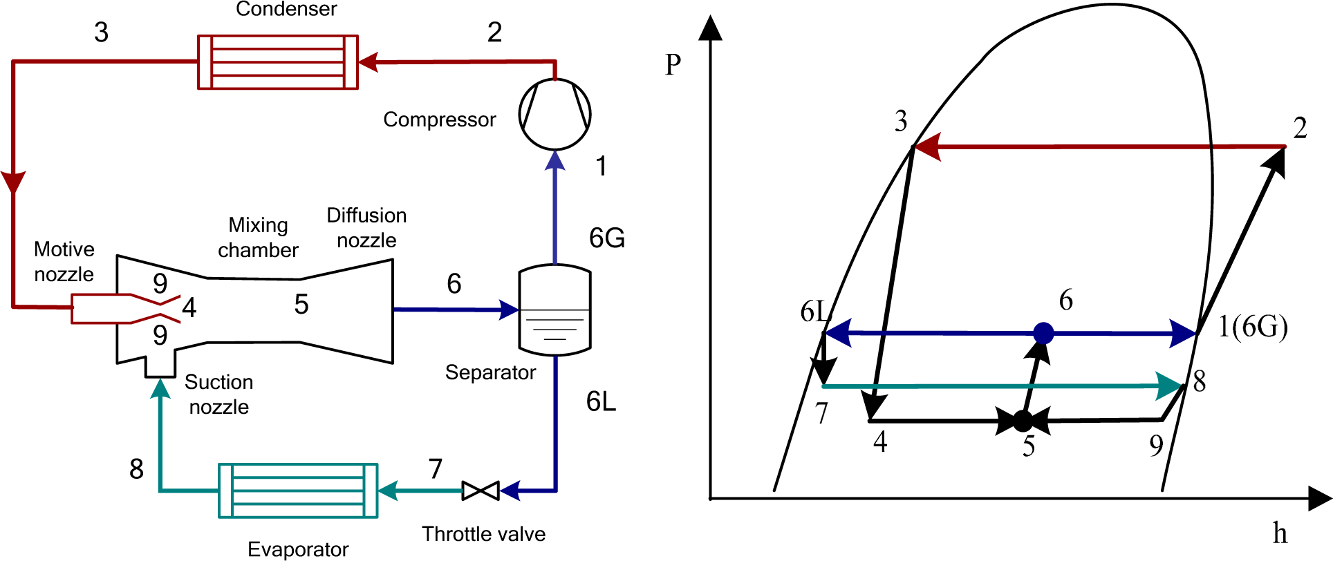
2. Cycle Description

A layout diagram of the two-phase ejector-expansion refrigeration cycle and the corresponding p-h diagram are shown in Figure 1. The high-pressure liquid exited from the condenser is expanded through the motive nozzle of the ejector. This expansion of the high-pressure liquid is then applied to entrain and raises the vapor pressure at the outlet of the evaporator. Then mixing occurred between the two streams in the mixing chamber. Next, the mixed fluid enters a diffusion nozzle, where the fluid are further decelerated and compressed to a pressure higher than the initial pressure of the suction stream. The two-phase fluid at the outlet of the ejector is sent to the liquid-vapor separator, where the vapor enters the compressor and ultimately becomes the motive stream, while the liquid returns to the evaporator through a throttle valve and ultimately becomes the suction stream. Compared with the basic cycle, the compression work required for the cycle is decreased owing to the higher compressor inlet pressure. Besides, an increase in evaporator capacity can be attained owing to the lower evaporator inlet enthalpy compared to an isenthalpic expansion.

3. Thermodynamic analysis

In order to simplify the calculation, the following assumptions are made:
  • One dimensional steady flow for the working fluid in the system.
  • Ignore the pressure loss in the heat exchangers and the pipes [1315,19].
  • Saturated vapor and liquid at the outlet of the gas-liquid separator.
  • Mixing occurs at a constant pressure, less than the inlet pressure of the suction flow.
  • Expansion processes and compression processes are all adiabatic. The ejector geometry effects are assumed to be considered in terms of isentropic efficiencies of the ejector components.
  • The separator offered zero pressure drop and had 100% effectiveness in separating the two-phase mixture into saturated vapor and liquid [13].
The mass entrainment ratio and the pressure lift ratio, shown in Equations (1) and (2), respectively, are the two main performance parameters of an ejector. The mass entrainment ratio indicates how much mass an ejector is able to entrain. The pressure lift ratio indicates the pressure increase that the ejector can provide to the entrained suction flow:
μ = m 8 / m 3
PLR ( pressure lift ratio ) = p 6 / p 8
In the EEC, the suction nozzle pressure drop (SNPD) provides the power for the suction flow. It is expressed as:
SNPD = p 8 p 9

3.1. Energy Analysis

The isentropic efficiency of the motive nozzle is defined as:
η mn = ( h 3 h 4 ) / ( h 3 h 4 s )
The energy conservation equation between the inlet and the exit of the motive nozzle is:
h 3 h 4 = ν 4 2 / 2
The exit area of the motive nozzle is:
a 4 = 1 / ( ρ 4 ν 4 )
The isentropic efficiency of the suction nozzle is defined as:
η sn = ( h 8 h 9 ) / ( h 8 h 9 s )
The energy conservation equation between the inlet and the exit of the suction nozzle is:
h 8 h 9 = ν 9 2 / 2
The exit area of the suction nozzle is:
a 9 = μ / ( ρ 9 ν 9 )
The momentum conservation equation between the inlet and the exit of mixing chamber is:
ν 5 = ( ν 4 + μ ν 9 ) / ( 1 + μ )
The energy conservation equation between the inlet and the exit of mixing chamber is:
h 3 / ( 1 + μ ) + μ h 8 / ( 1 + μ ) = h 5 + ν 5 2 / 2
The isentropic efficiency of the diffusion nozzle is given as:
η dn = ( h 6 s h 5 ) / ( h 6 h 5 )
The energy conservation equation in the diffusion nozzle is:
h 6 h 5 = ν 5 2 / 2
The energy conservation equation of the whole ejector can be written as:
μ h 3 + h 8 = ( 1 + μ ) h 6
The quality of the working fluid exiting from the ejector is:
x 6 = 1 / ( 1 + μ )
The ejector area ratio is:
A R = ( a 4 + a 9 ) / a 4
The isentropic efficiency of the compressor is:
η com = ( h 2 s h 1 ) / ( h 2 h 1 )
The isentropic efficiency of the compressor is determined by [22]:
η com = 0.874 0.0135 ( p 2 / p 1 )
The compressor work consumption per unit mass flow rate is:
w com = h 2 h 1
The evaporator refrigerating capacity per unit mass flow rate is:
q eva = ( h 8 h 7 ) μ
The cycle cooling coefficient of performance can be expressed as:
COP = q eva / w com
The volumetric cooling capacity of the cycle based on the specific inlet volume of the compressor is:
VCC = ( h 8 h 7 ) μ / ν 1
The improvements in COP and VCC of the EEC over basic cycle are:
iCOP = ( COP EEC COP BC ) / COP BC
iVCC = ( VCC EEC VCC BC ) / VCC BC

3.2. Exergy Analysis

For EEC, exergy analysis is significant to evaluate the decrease of irreversibility for every component and the whole cycle. In addition, exergy analysis can also help to evaluate the improvement degree in the exergy efficiency in comparison with the BC.
The specific exergy of the refrigerant is expressed as:
E x = ( h h 0 ) T 0 ( s s 0 )
For q at constant temperature T, the heat exergy rate exq can also be calculated by:
E x q = ( 1 T 0 / T ) q
Exergy destruction in the compressor is:
E x com = T 0 ( s 2 s 1 )
Exergy destruction in the condenser is:
E x con = h 2 h 3 T 0 ( s 2 s 3 )
Exergy destruction in the ejector is:
E x ej = T 0 ( ( 1 + μ ) s 6 s 3 μ s 8 ) )
Exergy destruction in the throttle valve is:
E x tv = T 0 ( s 7 s 6 L ) μ
Exergy destruction in the evaporator is:
E x eva = T 0 ( s 8 s 7 ) μ + T 0 / T r ( h 7 h 8 ) μ
Therefore, the total exergy losses of the cycle are:
E x tot = E x com + E x con + E x ej + E x tv + E x eva
The exergy efficiency of the cycle can be expressed as:
η ex = 1 E x tot / W com
The decrease in Extot and improvement in exergy efficiency of the EEC over basic cycle are:
i E x tot = ( E x tot , EEC E x tot , BC ) / E x tot , BC
i η ex = ( η ex , EEC η ex , BC ) / η ex , BC
Based on the theoretical model described above, the simulation code was developed to investigate the performance characteristics of the EECs using R32 and R134a for air-conditioning applications. The thermodynamic property data of the working fluid is based on REFPROP [23]. The algorithm of code for the EEC is as follows:
  • The property parameters at states 8 and 3 are calculated based on the given condensing temperature, evaporating temperature, subcooling and superheat.
  • The property parameters at states 9 and 4 are calculated by given ηmn, ηsn, and SNPD. Fluid velocities at the corresponding states are calculated by Equations (5) and (8).
  • Some value of μ is presumed.
  • The property parameters and fluid velocity at state 5 are calculated by Equations (10) and (11).
  • Enthalpy, pressure, vapor quality and other property parameters at state 6 are calculated by given ηdn and Equations (12)(14).
  • Steps (iii)–(v) are iterated until Equation (15) is satisfied.
  • The other performance parameters are calculated by the other equations.
The present model is validated with the theoretical data available in open literature for EEC using R1234yf and R134a as working fluid [19]. As seen from Figure 2, the values of maximum COP calculated based on the present model shows a fine agreement with that of [19].

4. Results and Discussion

Unless otherwise specified, the condensing temperature is set at 40 °C, the evaporating temperature is set at 5 °C, and the ejector is assumed to have the following efficiencies: ηmn = ηsn = ηdn = 0.85 [19,24]. The reference environment temperature is set at 27 °C.
Figure 3 shows the variations of the system COP and iCOP versus the SNPD for the two refrigerants R32 and R134a with the operating conditions of teva = 5 °C and tcon = 40 °C. Figure 4 shows the variations of the VCC and iVCC versus the SNPD for the two refrigerants R32 and R134a with the operating conditions of teva = 5 °C and tcon = 40 °C. It can be seen that the system COP goes up first to a maximum and then decreases with increased SNPD for the two refrigerants. This implies that the EECs of the two refrigerants all have an optimum SNPD that leads to a maximum COP for fixed condensing and evaporating temperatures. This general trend is consistent with the published literatures [19,2426]. The same inclination also can be seen for the VCC of the EEC versus the SNPD. At the investigated operating conditions of this study, the optimum SNPD is around 2.5 kPa and 10.0 kPa respectively for the two cycles using R32 and R134a as refrigerant.
For R32, the maximum COP and VCC are 5.74 and 6633 kJ/m3, respectively, and the EEC yields 4.99%–7.89% improvement in COP and 4.18%–6.52% improvement in VCC over the basic cycle. For R134a, the maximum COP and VCC of R134a EEC are 6.04 and 2733 kJ/m3 respectively, and the EEC provides 7.93%–10.44% improvement in COP and 7.56%–9.89% improvement in VCC over the basic cycle. This implies that two-phase ejectors, theoretically, have the potential for significant performance improvement even for subcritical cycles. Compared with R134a EEC, the R32 EEC has lower COP and gains lower benefit from the ejector. But like the basic refrigeration cycle, R32 EEC has theoretically 2.4 times VCC of R134a.
Figure 5 shows the variations of compression pressure ratio (CPR) and PLR versus the SNPD for the two refrigerants R32 and R134a with the operating conditions of teva = 5 °C and tcon = 40 °C. Figure 6 shows the variations of ejector mass entrainment ratio versus the SNPD for the two refrigerants R32 and R134a with the operating conditions of teva = 5 °C and tcon = 40 °C. It can be seen that with the increase of SNPD, the value of PLR goes up initially to a maximum and then decreases, and the corresponding CPR decreases initially to a lowest value and then increases. For the values of SNPD from 0 to 40 kPa, the PLR ranges from 1.041 to 1.063 and the corresponding CPR varies from 2.451 to 2.504 for the R32 EEC, whereas the PLR ranges from 1.071 to 1.091 and the corresponding CPR varies from 2.665 to 2.718 for the R134a EEC. The variation of ejector mass entrainment ratio with the SNPD shows same trend with the PLR. For the values of SNPD from 0 to 40 kPa, the ejector mass entrainment ratio ranges from 0.789 to 0.7926 and from 0.761 to 0.7659 for R32 EEC and R134a EEC respectively. The lower CPR value results in less compression work of the EEC. In addition, for fixed condensing temperature and evaporating temperature, the higher PLR implies a higher inlet pressure of the compressor and a lower inlet specific volume. The higher ejector mass entrainment ratio implies the greater mass flow rate through the evaporator under the same total mass flow rate of the system, which results higher cooling capacity of the evaporator. The higher the ejector PLR and mass entrainment ratio, the better the performance of the EEC is. Thus the SNPD with the highest PLR and mass entrainment ratio provides the optimum COP and VCC as shown in Figures 2 and 3.
Figure 7 shows the variations of COP and iCOP versus the area ratio (AR) for the two refrigerants R32 and R134a with the operating conditions of teva = 5 °C and tcon = 40 °C. It can be seen that there is an optimum area ratio (ARopt) that makes the COP of EEC attains a maximum value. The COP decreases below the ARopt due to fact that over expansion of the motive flow in the mixing chamber makes the available free area for the suction flow decline and finally the suction flow rate decreases; in excess of the ARopt, the entrainment ratio decreases owing to the less momentum of the motive flow [19]. The ARopt is about 110 and 12 respectively for the cycles using R32 and R134a as refrigerant. The area ratio has little influence when AR surpasses 60 for the R32 EEC.
Table 1 illustrates the exergy destructions in each component for both BC and EEC of the two refrigerants R32 and R134a with the operating conditions of teva = 5 °C and tcon = 40 °C. The exergy destructions in the EEC are calculated based on one unit mass flow rate of the compressor. As shown in Table 1, the highest irreversibility occurs in the condenser, and the lowest irreversibility takes place in the small expansion valve in the EEC. For R32, the exergy destruction of the throttling valve in the basic refrigeration cycle is 5.899 kJ/kg, whereas the combined exergy destruction of the ejector and a small valve is only 3.522 kJ/kg. For R134a, the exergy destruction of the expansion valve in the basic refrigeration cycle is 3.712 kJ/kg, whereas the combined exergy destruction of the ejector and a small valve is only 1.791 kJ/kg. It implies that the exergy destruction in the expansion process decreases by 40.29% and 51.75% for R32 and R134a respectively owing to the use of an ejector instead of a throttling valve. Moreover, the exergy destruction in the compression process decreases by 7.88% and 10.20% for R32 and R134a respectively, the exergy destruction in the condensing process decreases by 2.71% and 0.74% for R32 and R134a, respectively. Compared with BC, the evaporating takes place at the lower evaporation temperature in the EEC, resulting in slightly higher exergy destruction in evaporator for the two refrigerants. But this variation in the evaporation process can be neglected for total cycle exergy destruction. The combined above mentioned effects result in the improvement of the system. Thus the overall system exergy destruction of the EEC is lower than that of the BC, and the overall system exergy efficiency of the EEC is higher than that of the BC. Compared with the BC, the total exergy destruction of the EEC has reduced by 10.59% and 13.24% respectively for R32 and R134a. The overall exergy efficiency of the EEC increases by 7.70% and 10.57%, respectively, for R32 and R134a as a result of the recovered expansion work by ejector.
The performance of cycles being studied, including R32 BC, R32 EEC, R134a BC and R134a EEC, based on maximum system COP versus the condensing and evaporating temperatures is shown in Figures 8 and 9 respectively. It can be seen that like BC, the COPs of the R32 and R134a EECs decrease with the condensing temperature and increase with the evaporating temperature. The benefit of the ejector is increased (higher iCOP) at higher condensing temperatures or lower evaporating temperatures owing to the greater potential for expansion work recovery for both refrigerants. Compared with R134a EEC, the R32 EEC has lower COP and offers lower COP improvements over the corresponding BC. The system COP of the R32 and R134a EEC decreases from 8.464 to 3.643 and from 8.792 to 3.901 respectively as the condensing temperature increases from 30 to 55 °C. The system COP of the R32 and R134a EEC increases from 3.578 to 6.931 and from 3.749 to 7.298 respectively as the evaporating temperature increases from −10 to 10 °C. The R32 EEC and R134a EEC yields 5.22%–13.77% and 6.63%–17.83% improvement in COP over the corresponding BC respectively for the given ranges of evaporating and condensing temperatures. The COP of R32 EEC is 2.66%–10.03% higher than that of R134a basic cycle. Furthermore, it is also found from the calculation that the optimum SNPD value is almost independent of evaporating temperature or condensing temperature.
Figures 10 and 11 show the variations of the total exergy destruction of the investigated cycles with the condensing temperature and the evaporating temperature respectively. As the condensing temperature increases or the evaporating temperature decreases, the total exergy destruction of the investigated cycle increases. Because the compressor pressure ratio becomes higher, the compressor will need more input work, and the heat rejection in the condenser will be higher for the same cooling capacity, resulting in higher exergy destruction for the cycle. Compared with R134a EEC, the R32 EEC has higher total exergy destruction and offers lower exergy destruction decrement over the corresponding BC. The application of an ejector instead of a throttle valve decreases the cycle’s total exergy destruction by 8.84%–15.84% and 10.16%–19.38% for R32 and R134a, respectively, under the given ranges of evaporating and condensing temperatures. Furthermore, the decrement ratio is increased (higher iEx) at higher condensing temperatures or lower evaporating temperatures owing to the greater potential for expansion work recovery for both refrigerants.
Figures 12 and 13 show the variation of the exergy efficiency of the investigated cycles with the condensing temperature and the evaporating temperature respectively for the two refrigerants R32 and R134a. As the condensing temperature or the evaporating temperature increases, the exergy efficiency of the investigated cycles decreases. Compared with R134a EEC, the R32 EEC has lower exergy efficiency and offers lower exergy efficiency improvement over the corresponding BC. The exergy efficiency of the R32 and R134a EEC varies from 0.2189 to 0.5081 and from 0.2346 to 0.5284 respectively as the condensing temperature increases from 30 to 55 °C. The exergy efficiency of the R32 and R134a EEC varies from 0.2884 to 0.4271 and from 0.3024 to 0.4445, respectively, as the evaporating temperature increases from −10 to 10 °C. The variations of the exergy efficiency with the condensing temperature or evaporating temperature are based on two parameters (Equation (33)): total exergy destruction and the compressor actual work. Both of the two parameters increase with the increase of the condensing temperature, but the total exergy destruction increases faster than that of the compressor actual work, which results in the decrease of exergy efficiency with the condensing temperature. Both the total exergy destruction and the compressor actual work decrease with the increase of the evaporator temperature. But the total exergy destruction decreases slower than that of the compressor actual work, which results in the decrease of exergy efficiency with the evaporating temperature. The application of an ejector instead of a throttle valve yields 5.13%–13.83% and 6.68%–17.95% improvement in exergy efficiency over the corresponding BC respectively for R32 and R134a under the given ranges of evaporating and condensing temperatures. The exergy efficiency improvement is increased (higher iηex) at higher condensing temperatures or lower evaporating temperatures owing to the greater potential for expansion work recovery for both refrigerants.
Figure 14 displays the influence of efficiencies of ejector components including the motive nozzle, suction nozzle and diffusion nozzle on the optimum SNPD with the operating conditions of teva = 5 °C and tcon = 40 °C. It can be seen that the optimum SNPD first increases slowly and then rapidly with the increase of each component efficiency. The efficiencies of the components have a significant impact on the optimum values of SNPD for R134a. With the efficiency increasing from 0 to 1, the optimum SNPD varies from 0 to 13kPa for the motive nozzle and suction nozzle, and varies from 0 to 17kPa for diffusion nozzle. Whereas the effects of the efficiencies of nozzles on the optimum SNPD is relatively small for R32. The optimum SNPD increases only from 0 to 3 kPa with the efficiency of the nozzle increasing from 0 to 1. Among these components, the effect of the diffusion nozzle efficiency on the optimum SNPD is relatively more significant.
Figure 15 illustrates the variations of the iCOP versus the efficiency of each ejector component with the operating conditions of teva = 5 °C and tcon = 40 °C. As can be seen, iCOP increases with the increase in the efficiency of each component. However, the suction nozzle efficiency on the EEC performance is comparative less among the three components. This is consistent with the published papers [19]. With the efficiency increasing from 0 to 1 for motive nozzle, suction nozzle and diffusion nozzle, the increment of iCOP are about 9.52%, 0.45% and 9.58%, respectively, for R32, the increment of iCOP are about 12.56%, 3.00% and 13.30%, respectively, for R134a. This implies that in the design of ejector for the EEC, more attention should be paid to the optimization of diffusion nozzle and the motive nozzle.

5. Conclusions

In this paper, the performance of ejector-expansion refrigeration cycle using R32 is presented in comparison with R134a through the energetic and exergetic analysis under the typical air conditioning operating conditions. The following conclusions are drawn from the results of the present study:
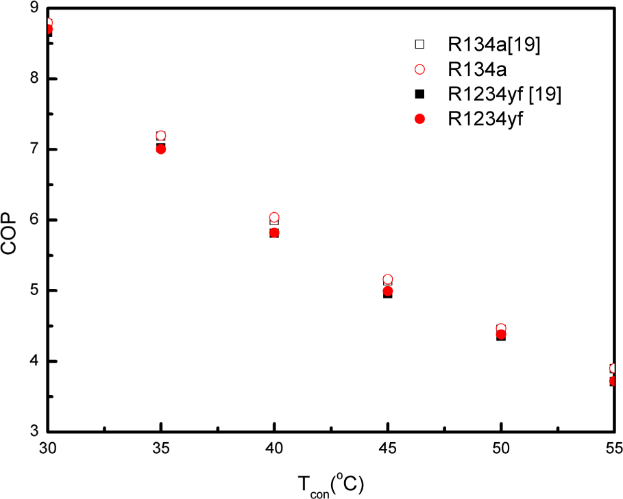
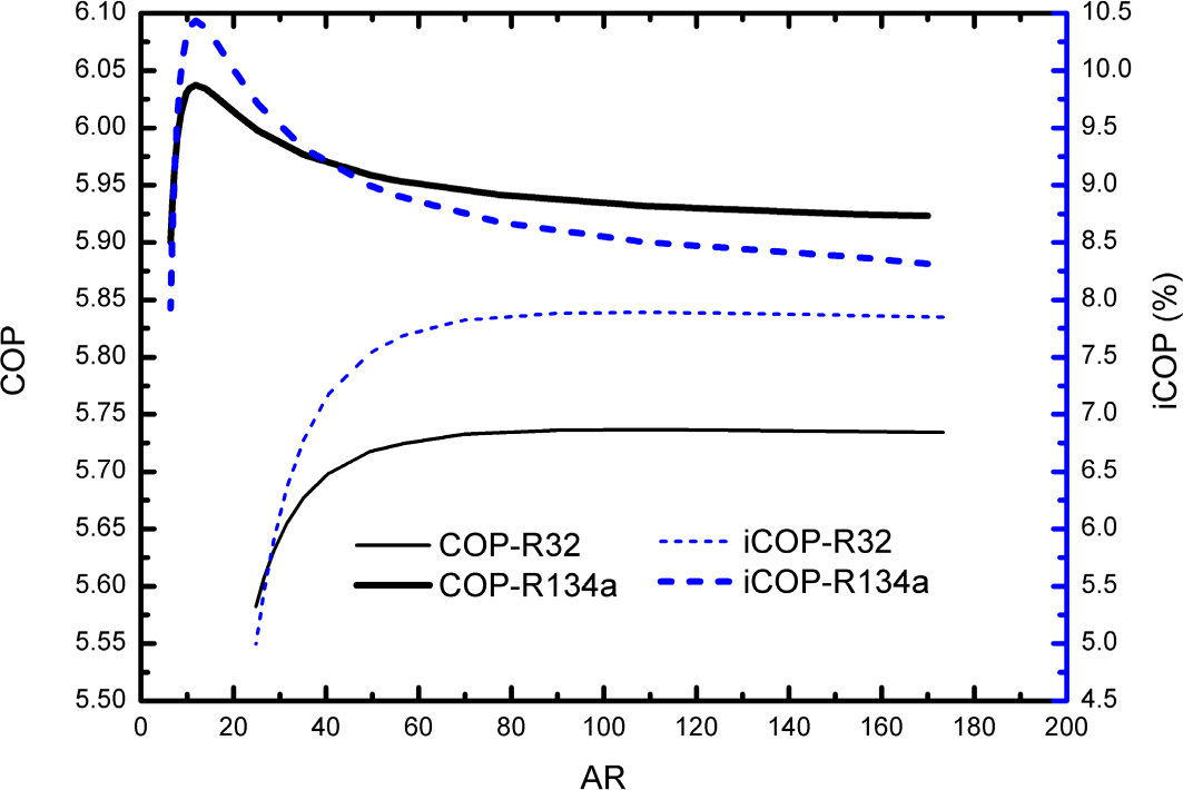
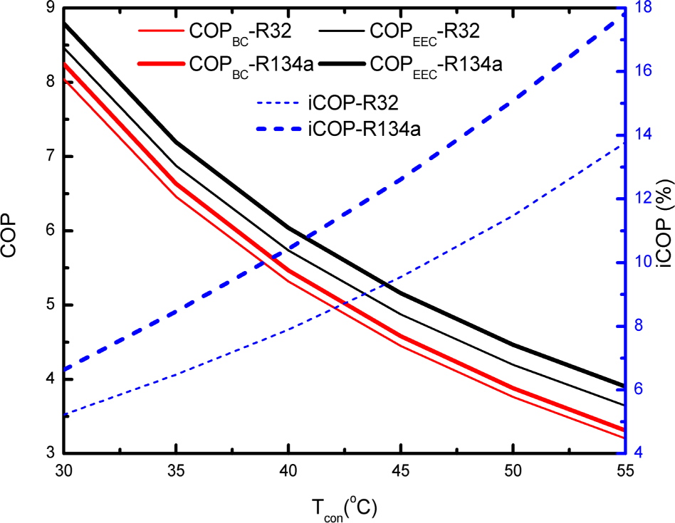
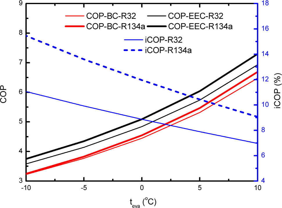
  • The cycle COP of R32 and R134a EEC are at a range of 3.578–8.464 and 3.749–8.792, respectively. The R32 EEC and the R134a EEC have a 5.22%–13.77% and 6.63%–17.83% improvement in COP over the corresponding basic cycle, respectively.
  • The application of an ejector instead of a throttle valve decreases the cycle’s total exergy destruction by 8.84%–15.84% and 10.16%–19.38% for R32 and R134a, respectively.
  • The exergy efficiency of the R32 and R134a EEC varies from 0.2189 to 0.5081 and from 0.2346 to 0.5284, respectively. The application of an ejector instead of a throttle valve yields 5.13%–13.83% and 6.68–17.95% improvement in exergy efficiency over the corresponding basic cycle respectively for R32 and R134a.
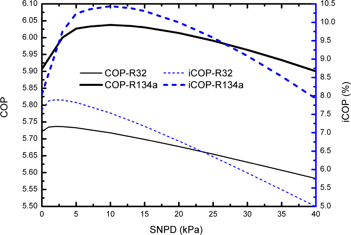
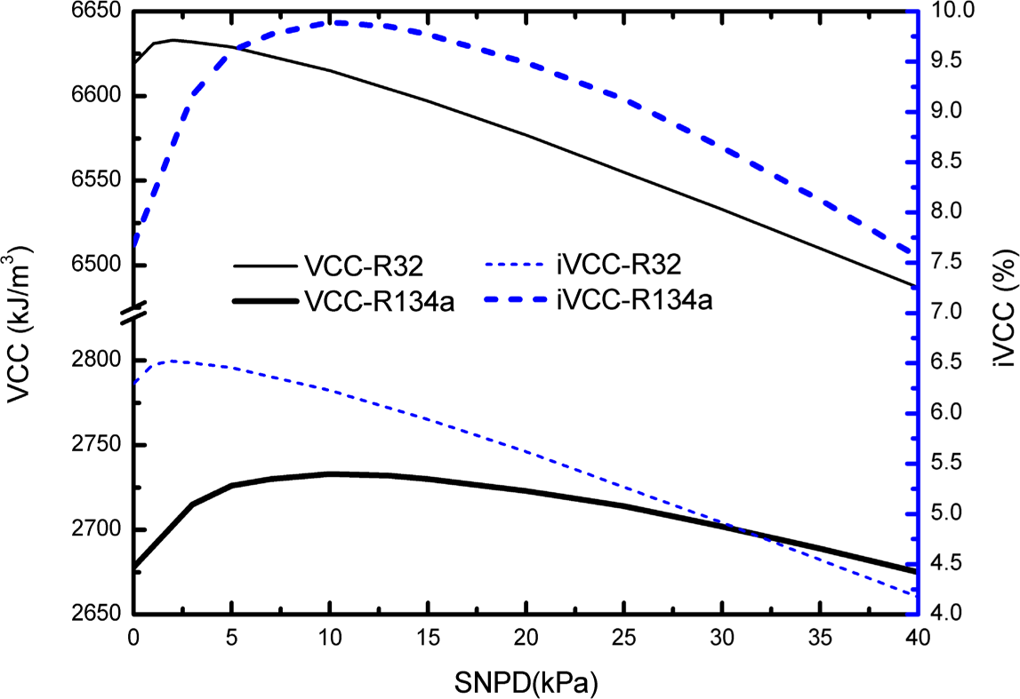
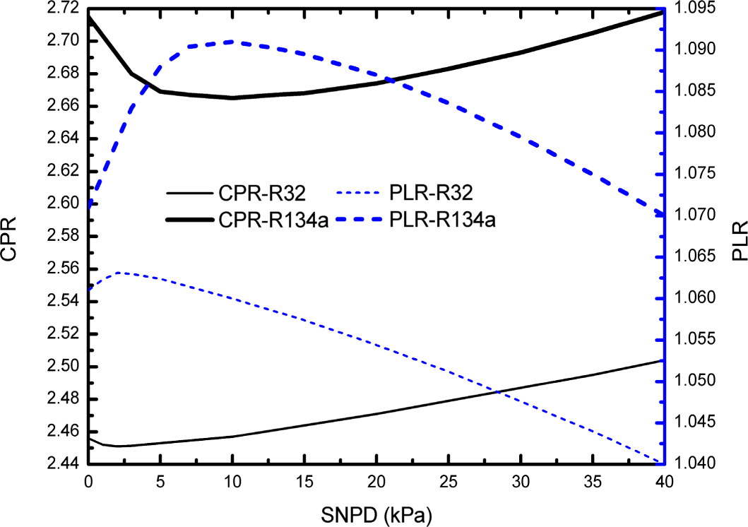
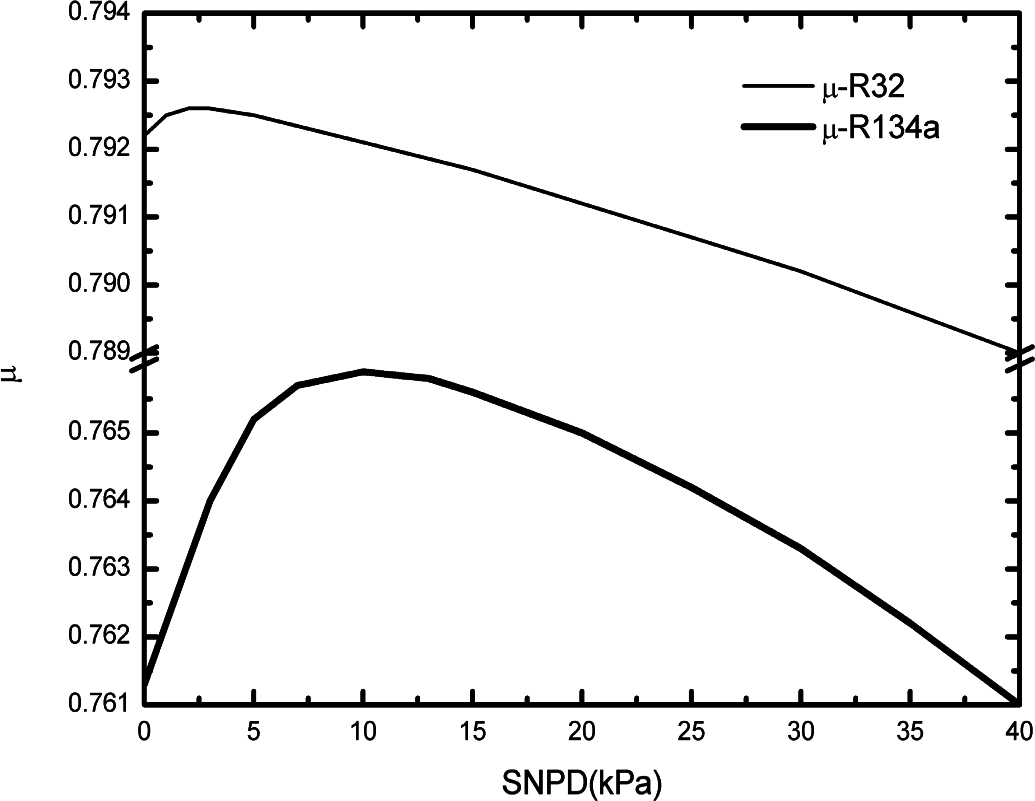
  • There exists an optimum SNPD which gives a maximum system COP and VCC under a specified condition. The value of the optimum SNPD mainly depends on the efficiencies of the ejector components, but is virtually independent of evaporating temperature and condensing temperature. The optimum SNPD varies from 0 to 3 kPa and from 0 to 17 kPa for R32 and R134a respectively. Among the components of ejector, the effect of the diffusion nozzle efficiency on the optimum SNPD is relatively more significant. In addition, the improvement of the component efficiency, especially the efficiencies of diffusion nozzle and the motive nozzle, can enhance the EEC performance.

Nomenclature

BC
basic refrigeration cycle
COP
coefficient of performance
CPR
compression pressure ratio
EEC
ejector-expansion refrigeration cycle
Ex
exergy [kJ/kg]
h
enthalpy [kJ/kg]
iCOP
improvement of COP
iEx
variation ratio of exergy destruction
iVCC
improvement of volumetric cooling capacity
m
mass flow rate [kg/s]
p
pressure [kPa]
PLR
pressure lift ratio
q
specific heat transfer rate [kJ/kg]
s
specific entropy [kJ/(kg.K)]
SNPD
suction nozzle pressure drop [kPa]
t
temperature [°C]
T
temperature [K]
v
velocity [m/s]
VCC
volumetric cooling capacity [kJ/m3]
w
specific power [kJ/kg]
x
vapor quality
η
efficiency
μ
entrainment ratio of ejector
Subscripts
0
reference environment
com
compressor
con
condenser
dn
diffusion nozzle
eva
evaporator
mix
mixing chamber
hx
heat exchanger
mn
motive nozzle
r
refrigerated object
sn
suction nozzle
tot
totle
tv
throttle valve

Acknowledgments

The authors appreciate the support of Natural Science Foundation of Hebei Province (NO. E2014209044), Tangshan Science and Technology Research Projects (NO. 13130299b), and Natural Science Foundation of China (NO.51378172).

Author Contributions

Zhenying Zhang proposed the key idea of this paper. Zhenying Zhang, Lirui Tong and Li Chang did the theoretical work. Yanhua Chen and Xingguo Wang guided the whole research process. All authors contributed to write the paper. All authors have read and approved the final manuscript.

Conflicts of Interest

The authors declare no conflict of interest.

References

  1. Elbel, S. Historical and present developments of ejector refrigeration systems with emphasis on transcritical carbon dioxide air-conditioning applications. Int. J. Refrig. 2011, 34, 1545–1561. [Google Scholar]
  2. Ahammed, M.E.; Bhattacharyya, S.; Ramgopal, M. Thermodynamic design and simulation of a CO2 based transcritical vapour compression refrigeration system with an ejector. Int. J. Refrig. 2014, 45, 177–188. [Google Scholar]
  3. Goodarzi, M.; Gheibi, A.; Motamedian, M. Comparative analysis of an improved two-stage multi-inter-cooling ejector-expansion trans-critical CO2 refrigeration cycle. Appl. Therm. Eng. 2015, 81, 58–65. [Google Scholar]
  4. Lee, J.S.; Kim, M.S.; Kim, M.S. Studies on the performance of a CO2 air conditioning system using an ejector as an expansion device. Int. J. Refrig. 2014, 38, 140–152. [Google Scholar]
  5. Li, D.; Groll, E.A. Transcritical CO2 refrigeration cycle with ejector-expansion device. Int. J. Refrig. 2005, 28, 766–773. [Google Scholar]
  6. Liu, F.; Groll, E.A.; Li, D. Investigation on performance of variable geometry ejectors for CO2 refrigeration cycles. Energy 2012, 45, 829–839. [Google Scholar]
  7. Nakagawa, M.; Marasigan, A.R.; Matsukawa, T.; Kurashina, A. Experimental investigation on the effect of mixing length on the performance of two-phase ejector for CO2 refrigeration cycle with and without heat exchanger. Int. J. Refrig. 2011, 34, 1604–1613. [Google Scholar]
  8. Zhang, Z.-Y.; Ma, Y.-T.; Wang, H.-L.; Li, M.-X. Theoretical evaluation on effect of internal heat exchanger in ejector expansion transcritical CO2 refrigeration cycle. Appl. Therm. Eng. 2013, 50, 932–938. [Google Scholar]
  9. Sumeru, K.; Nasution, H.; Ani, F.N. A review on two-phase ejector as an expansion device in vapor compression refrigeration cycle. Renew. Sustain. Energy Rev. 2012, 16, 4927–4937. [Google Scholar]
  10. Manjili, F.E.; Yavari, M.A. Performance of a new two-stage multi-intercooling transcritical CO2 ejector refrigeration cycle. Appl. Therm. Eng. 2012, 40, 202–209. [Google Scholar]
  11. Banasiak, K.; Palacz, M.; Hafner, A.; Buliński, Z.; Smołka, J.; Nowak, A.J.; Fic, A. A CFD-based investigation of the energy performance of two-phase R744 ejectors to recover the expansion work in refrigeration systems: An irreversibility analysis. Int. J. Refrig. 2014, 40, 328–337. [Google Scholar]
  12. Kornhauser, A.A. The use of an ejector as a refrigerant expander. Proceedings of the 1990 USNC/IIR-Purdue Refrigeration Conference, West Lafayette, IN, USA, 14–17 July 1990; pp. 10–19.
  13. Domanski, P.A. Theoretical Evaluation of the Vapor Compression Cycle with a Liquid-Line/Suction-Line Heat Exchanger, Economizer, and Ejector; National Institute of Standards and Technology: Gaithersburg, MD, USA, 1995. [Google Scholar]
  14. Nehdi, E.; Kairouani, L.; Bouzaina, M. Performance analysis of the vapour compression cycle using ejector as an expander. Int. J. Energy Res. 2007, 31, 364–375. [Google Scholar]
  15. Bilir, N.; Ersoy, H.K. Performance improvement of the vapour compression refrigeration cycle by a two-phase constant area ejector. Int. J. Energy Res. 2009, 33, 469–480. [Google Scholar]
  16. Disawas, S.; Wongwises, S. Experimental investigation on the performance of the refrigeration cycle using a two-phase ejector as an expansion device. Int. J. Refrig. 2004, 27, 587–594. [Google Scholar]
  17. Wongwises, S.; Disawas, S. Performance of the two-phase ejector expansion refrigeration cycle. Int. J. Heat Mass Transf. 2005, 48, 4282–4286. [Google Scholar]
  18. Pottker, G.; Hrnjak, P. Ejector in R410A vapor compression systems with experimental quantification of two major mechanisms of performance improvement: Work recovery and liquid feeding. Int. J. Refrig. 2015, 50, 184–192. [Google Scholar]
  19. Li, H.; Cao, F.; Bu, X.; Wang, L.; Wang, X. Performance characteristics of R1234yf ejector-expansion refrigeration cycle. Appl. Energy. 2014, 121, 96–103. [Google Scholar]
  20. Bilir Sag, N.; Ersoy, H.K.; Hepbasli, A.; Halkaci, H.S. Energetic and exergetic comparison of basic and ejector expander refrigeration systems operating under the same external conditions and cooling capacities. Energy Convers. Manag. 2015, 90, 184–194. [Google Scholar]
  21. Lawrence, N.; Elbel, S. Experimental investigation of a two-phase ejector cycle suitable for use with low-pressure refrigerants R134a and R1234yf. Int. J. Refrig. 2014, 38, 310–322. [Google Scholar]
  22. Brunin, O.; Feidt, M.; Hivet, B. Comparison of the working domains of some compression heat pumps and a compression-absorption heat pump. Int. J. Refrig. 1997, 20, 308–318. [Google Scholar]
  23. Lemmon, E.; Huber, M.; McLinden, M. NIST Reference Fluid Thermodynamic and Transport Properties—REFPROP, Version 8.0; National Institute of Standards and Technology: Gaithersburg, MD, USA, 2007. [Google Scholar]
  24. Sarkar, J. Performance characteristics of natural-refrigerants-based ejector expansion refrigeration cycles. Proc. Inst. Mech. Eng. A 2009, 223, 543–550. [Google Scholar]
  25. Ersoy, H.K.; Bilir, N. Performance characteristics of ejector expander transcritical CO2 refrigeration cycle. Proc. Inst. Mech. Eng. A 2012, 226, 623–635. [Google Scholar]
  26. Zhang, Z.; Tian, L. Effect of suction nozzle pressure drop on the performance of an ejector-expansion transcritical CO2 refrigeration cycle. Entropy 2014, 16, 4309–4321. [Google Scholar]
Figure 1. Schematic and P-h diagram of the ejector-expansion refrigeration cycle.
Entropy 17 04744f1
Figure 2. Comparison of the present simulation results with Li et al. [19] results.
Entropy 17 04744f2
Figure 3. Influence of SNPD on COP and iCOP.
Entropy 17 04744f3
Figure 4. Influence of SNPD on VCC and iVCC.
Entropy 17 04744f4
Figure 5. Influence of SNPD on CPR and PLR.
Entropy 17 04744f5
Figure 6. Influence of SNPD on μ.
Entropy 17 04744f6
Figure 7. Influence of AR on COP and iCOP.
Entropy 17 04744f7
Figure 8. Influence of condensing temperature on COP and iCOP.
Entropy 17 04744f8
Figure 9. Influence of evaporating temperature on COP and iCOP.
Entropy 17 04744f9
Figure 10. Influence of condensing temperature on Extot and iExtot.
Entropy 17 04744f10
Figure 11. Influence of evaporating temperature on Extot and iExtot.
Entropy 17 04744f11
Figure 12. Influence of condensing temperature on ηex and iηex.
Entropy 17 04744f12
Figure 13. Influence of evaporating temperature on ηex and iηex.
Entropy 17 04744f13
Figure 14. Influence of ejector component efficiencies on optimum SNPD.
Entropy 17 04744f14
Figure 15. Influence of ejector component efficiencies on iCOP.
Entropy 17 04744f15
Table 1. Exergy destructions and exergy efficiency of the investigated cycles
ProcessR32
R134a
BC
EEC
BC
EEC
Ex (kJ/kg)(%)Ex (kJ/kg)(%)Ex (kJ/kg)(%)Ex (kJ/kg)(%)
Compression6.39820.785.89421.414.12623.153.70523.97
Condensing14.0545.6313.6749.657.31641.057.26246.99
Ejector3.43812.491.76911.45
Throttling5.89919.160.083960.313.71220.830.022120.14
Evaporation4.44314.434.44716.152.67014.982.69717.45
Total30.7910027.5310017.8210015.46100
ηex0.31940.3440.32840.3631

