1. Introduction
High-voltage direct-current (HVDC) transmission systems have been widely applied to power transmission projects with long overhead transmission lines, bulk power and asynchronous interconnections because of their lower-cost transmission lines and larger power transmission capability [
1,
2]. However, their remote distance, complex surroundings and unpredictable weather conditions lead to a high failure rate, which requires protection methods with high reliability, fast response ability and sufficient sensitivity. There exist several problems in the current commonly used protection methods, including traveling-wave protection, dc minimum voltage protection and dc differential protection [
3]. That is, if a fault is not properly detected or removed, it might cause widespread damage or a power system blackout [
4]. Aiming to preserve the stability and reliability of HVDC transmission systems, it is crucial to find new protection principles for further study.
Based on the characteristics of the reactor-filter unit, which is made of a smoothing reactor and dc-side filter, the absolute-value integration of one-end current signals in some particular frequency bands were used to formulate the protection criteria [
1]. However, high-resistance grounding leads to a fairly small current so that the current in characteristic frequency bands might be smaller than the setting value when a fault occurs. Therefore a protection system using one-end current would fail to operate. By this reason, in [
5], according to the comparison of the energy of the forward and backward voltage traveling wave, the fault position can be recognized. Moreover, a pilot directional protection scheme for HVDC transmission line is proposed, which extracts the direction feature of specific frequency current through spectrum analysis and integral [
6,
7]. However, these methods don’t have strong robustness to noise because the integral cannot get rid of noise disturbance and the fault current energy would be low and the integral would be much smaller when a high-resistance fault occurs.
To improve the reliability of the protection algorithms, signal processing was introduced into transmission line protection. For instance, in [
8] Wavelet Transform (WT) has been applied to extract transient characteristics of different fault conditions for analyzing various transient voltage traveling waves. WT has the function of filtering, which can get rid of noise disturbance [
9]. In [
10], a technique similar to Discrete Fourier Transform (DFT) is presented for decomposing the transient components of current signals. Due to the effectiveness of WT in transient analysis, this technique has been combined with other techniques with the aim of improving the reliability of protection schemes. In [
11,
12,
13], Shannon entropy is combined with WT which acts as an automatic feature extractor for distinguishing stable and unstable power swings. In other words, wavelet entropy can identify the power signals with different complexity. Therefore, in [
14,
15] the wavelet singular entropy is applied to describe the signals with different complexity which can distinguish internal fault from external fault. Moreover, wavelet energy entropy has a unique sensibility to slight change of signals and it can reflect the energy distribution information in both time and frequency domain [
16,
17]. In [
18], relative entropy is considered to be a measure of the normal signals and the faulty signals, which can discriminate between the faulty groups and the normal groups.
In this paper, a novel algorithm for transmission line protection is proposed following the principle of relative entropy of wavelet energy, having improved the reliability of protection method proposed in [
7] under high resistance grounding fault conditions and its anti-noise property. Furthermore, the proposal is based on the analysis of the HVDC transmission system and its superimposed circuit which indicate the directional features of the voltage and current. The results are discussed with the aim to assess the advantages of the proposed algorithm and its reliability under different fault conditions. The proposed protection method can recognize internal faults correctly and quickly.
3. Fault Feature Analysis
Nowadays, most HVDC transmission projects are two-end bipolar DC transmission systems.
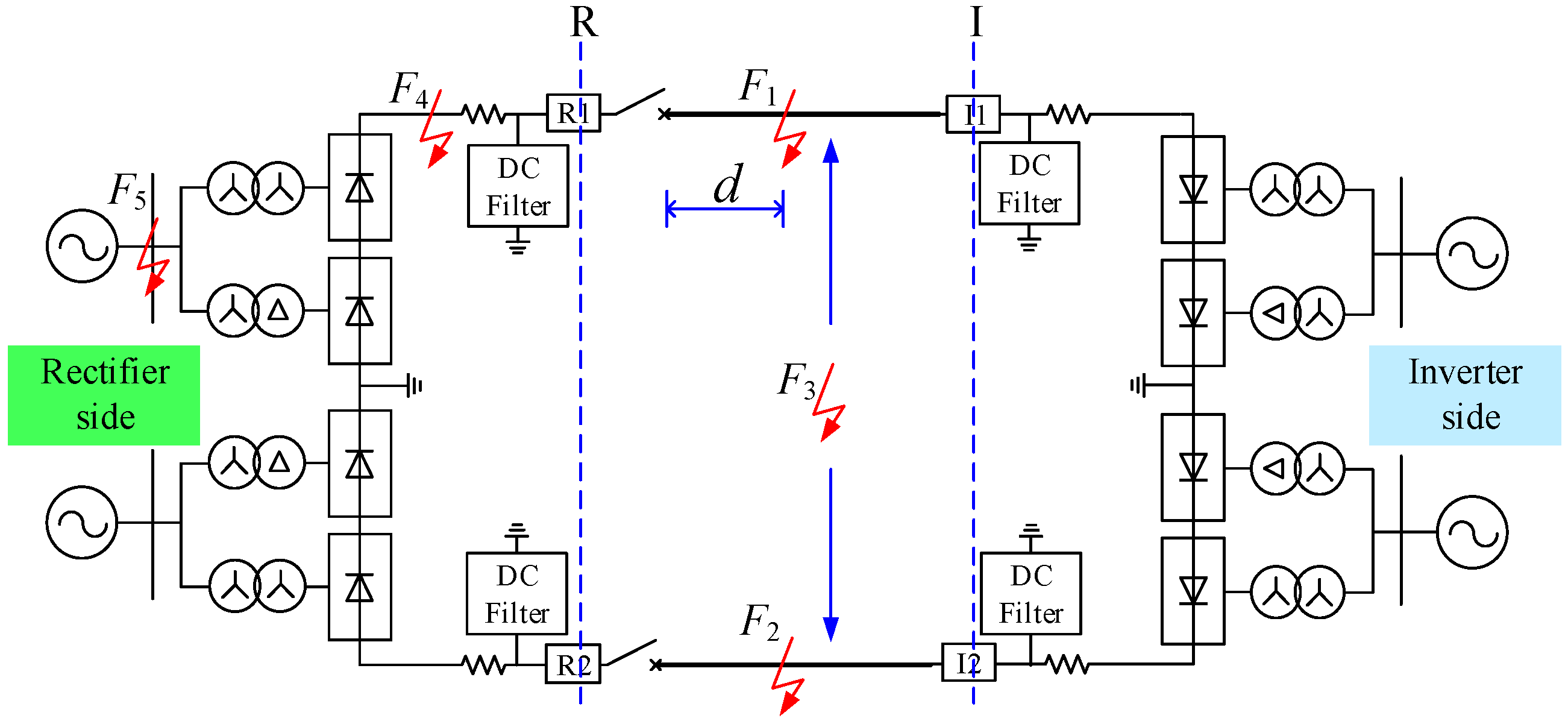
Figure 1 shows the structure of a bipolar HVDC transmission system composed of converter transformers, converters, smoothing reactor, AC filter, DC filter and transmission line. Each converter unit is comprised of two 12-pulse converters in series. Protection equipment is installed on both sides of the transmission line, R and I are the positions where protection and measurement devices installed on the rectifier side and the invertor side respectively. 1 and 2 separately represent the positive pole and negative pole.
Figure 1.
Bipolar HVDC transmission system structure.
Figure 1.
Bipolar HVDC transmission system structure.
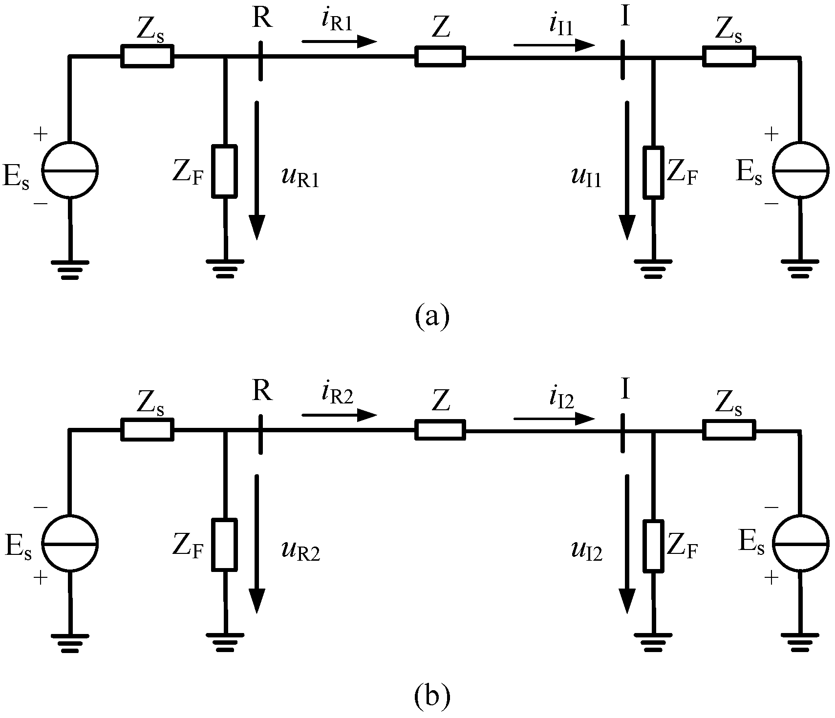
According to the superposition principle, if a circuit has two or more independent sources, it can be analyzed by determining the contribution of each independent source to the variable and adding them up. Therefore, a fault state can be equivalent to the superposition of the normal state and an additional fault state. To simplify the HVDC transmission system, the AC side and converter station are equivalent to DC power supply while the smoothing filter and DC filter are equivalent to fixed impedance, which is represented by
ZF. Though the simplification cannot reflect the fault transient, it doesn’t affect diagnosis using the characteristic of voltage and current. The line current and line voltage on each side of the simplified system when the HVDC transmission system operates normally are shown in
Figure 2a,b.
is the equivalent impedance of the transmission line.
is the voltage source of the equivalent model of AC system, while
is the impedance of the equivalent model of AC system.
Figure 2.
Simplified monopole HVDC transmission system without fault. (a) Simplified positive pole HVDC transmission system. (b) Simplified negative pole HVDC transmission system.
Figure 2.
Simplified monopole HVDC transmission system without fault. (a) Simplified positive pole HVDC transmission system. (b) Simplified negative pole HVDC transmission system.
3.1. Internal Fault
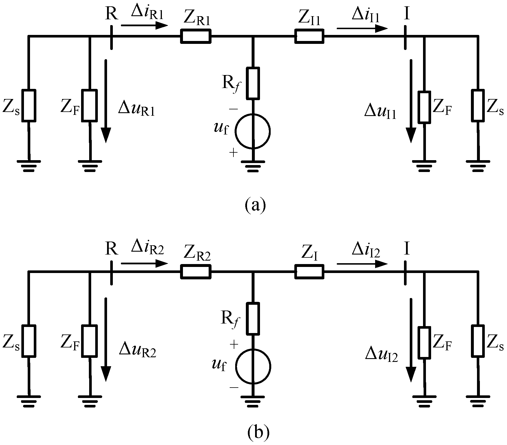
When transmission lines have grounding faults (internal faults occurring in transmission lines),
Figure 3a is the superimposed circuit for a positive line fault and
Figure 3b is the superimposed circuit for a negative line fault. The simplified model of the positive pole and negative pole transmission line can be analyzed independently, which is reckoned without the interaction of transmission lines after decoupling.
Figure 3.
Fault superimposed circuit for an internal fault. (a) Simplified positive pole HVDC transmission system. (b) Simplified negative pole HVDC transmission system.
Figure 3.
Fault superimposed circuit for an internal fault. (a) Simplified positive pole HVDC transmission system. (b) Simplified negative pole HVDC transmission system.
3.1.1. Positive Pole
An internal fault on a positive pole transmission line is equivalent to a negative voltage source at the fault position. Supposing that the voltage measured at the converter station doesn’t change at transient analysis after a fault, then the superimposed circuit of positive pole transmission system is as shown in
Figure 3a.
Since a grounding fault occurs in the middle of two boundaries of the positive transmission line, let
and
be the equivalent impedance of the transmission line close to the rectifier and inverter, respectively, and
.
is the ground resistance while
represents the equivalent voltage source at the fault position.
,
,
and
are the voltage fault components and current fault components measured on each side of the positive pole transmission line. When a fault occurs on the positive pole transmission line:
where the directions of
and
are opposite, while the directions of
and
are identical.
3.1.2. Negative Pole
The superimposed circuit of a negative pole transmission system is as shown in
Figure 3b with a positive voltage source acting at the fault position.
In
Figure 3b, similar to the positive pole,
,
,
and
are the voltage fault components and current fault components measured on each side of the negative pole transmission line. When a fault occurs on the negative pole transmission line:
where the directions of
and
are opposite, while the directions of
and
are identical. If two transmission lines encounter a short circuit, the fault superimposed circuit of the positive pole and negative pole are shown as in
Figure 3 after all. Thus, the directions of voltage fault components and current fault components on the rectifier-side are opposite while the directions on the inverter-side are identical.
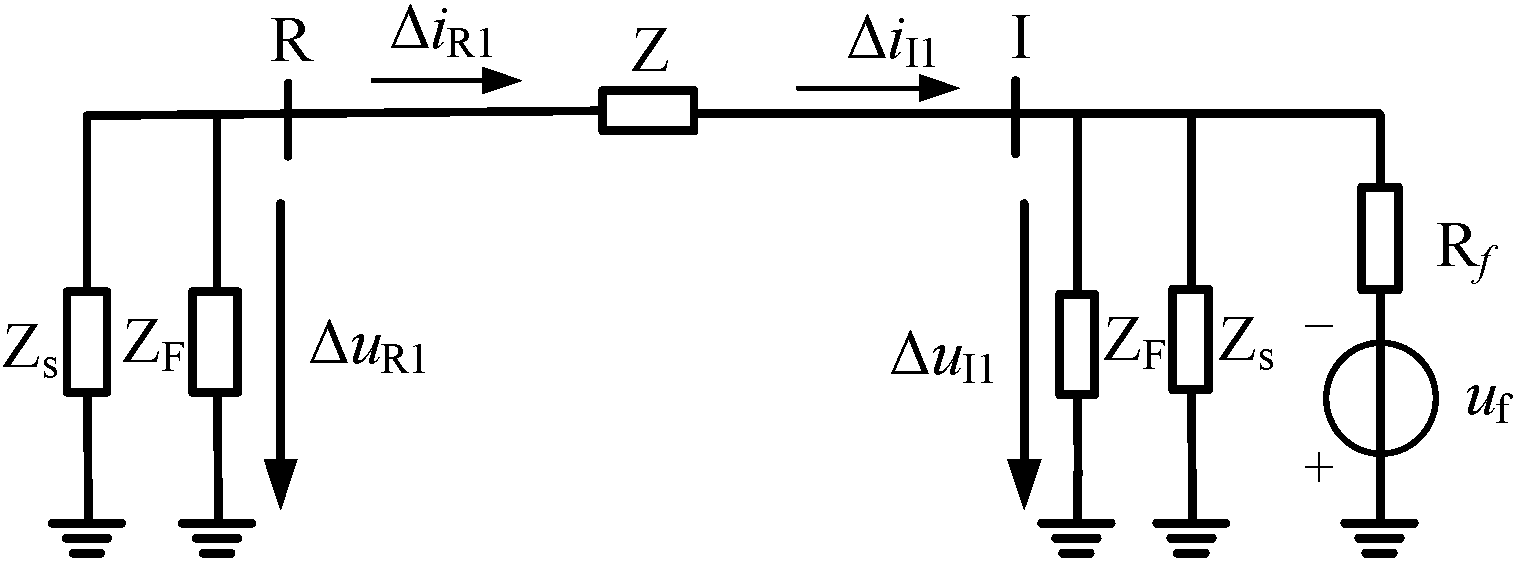
3.2. External Fault
3.2.1. External Fault at the Rectifier-Side
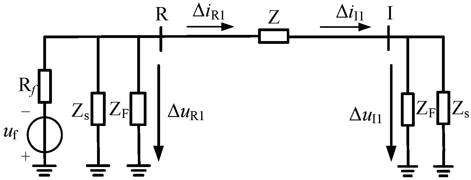
When a fault occurs to a positive pole transmission system at the rectifier-side, the superimposed circuit is as shown by
Figure 4.
Figure 4.
Fault superimposed circuit for an external fault at the rectifier-side on the positive pole.
Figure 4.
Fault superimposed circuit for an external fault at the rectifier-side on the positive pole.
The circuit in
Figure 4 involves a dependent voltage source. To gain the relationship between current and voltage, applying KVL around the loop in
Figure 4 gives:
where the directions of
,
and the directions of
,
are all identical.
If a fault occurs to the negative pole transmission system at the rectifier-side, a similar superimposed circuit with positive pole transmission is shown as is
Figure 4, except for the direction of
. Therefore, the relationship between voltage fault components and current fault components on both sides of transmission line is:
where the directions of
,
and the directions of
,
are all identical.
Therefore, when an external fault occurs to a HVDC transmission system at the rectifier-side, the directions of the voltage fault components and current fault components on each side of transmission lines are identical.
3.2.2. External Fault at Inverter-Side
The superimposed circuit for an external fault at the inverter-side of a positive pole transmission system is as shown in
Figure 5.
Figure 5.
Fault superimposed circuit for an external fault at the inverter-side on the positive pole.
Figure 5.
Fault superimposed circuit for an external fault at the inverter-side on the positive pole.
Applying KVL around the loop in
Figure 5 gives:
where the directions of
,
are opposite and the directions of
,
are also opposite.
Similarly, when an external fault occurs to a negative pole transmission system at the inverter-side, the fault components are calculated as below:
where the directions of
,
are opposite and the directions of
,
are also opposite.
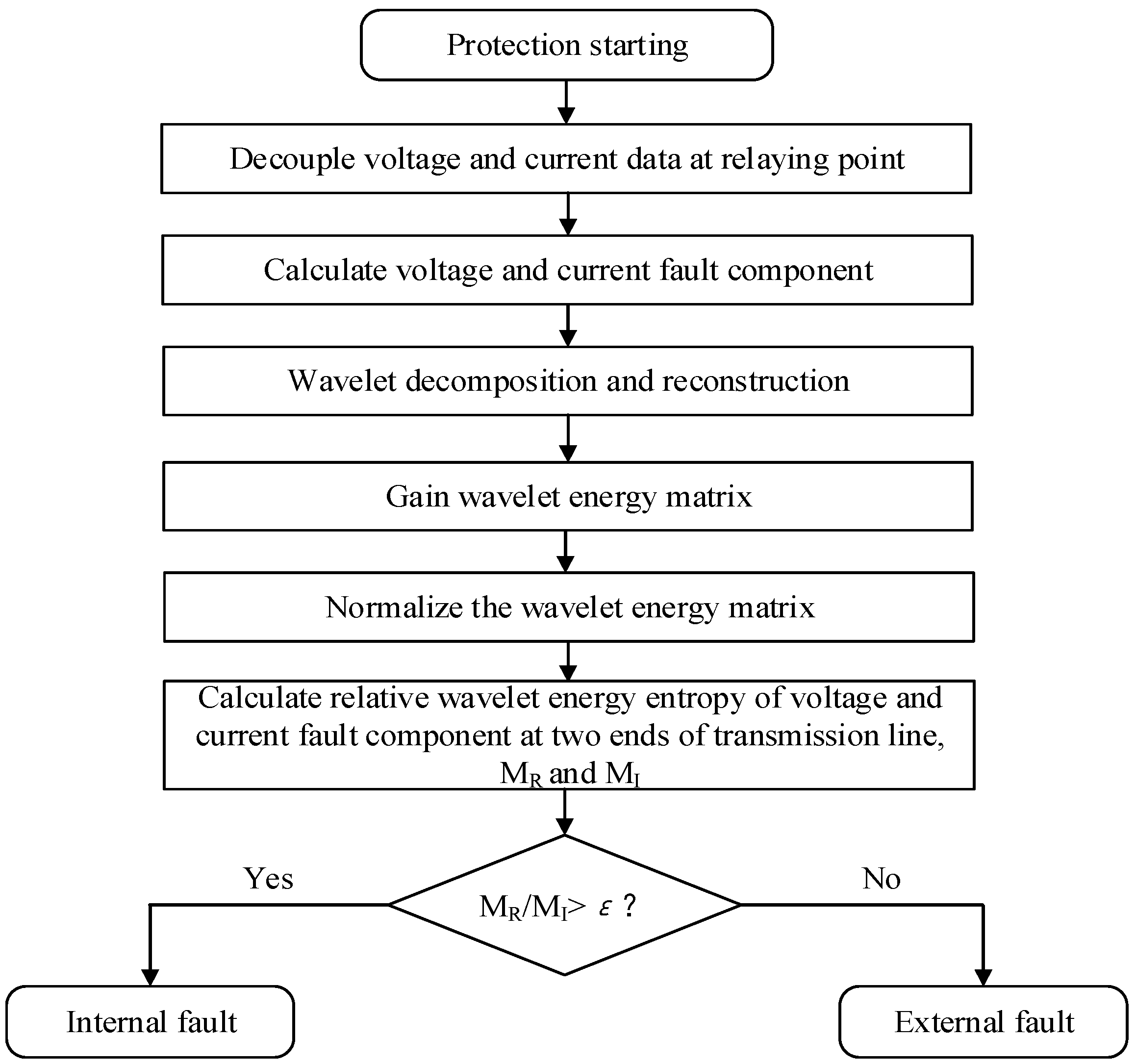
3.3. Summary
For internal fault, the directions of voltage and current fault components at the rectifier-side are opposite while the directions at the inverter-side are identical. However, for external faults, no matter whether at the rectifier-side or inverter-side, the relationship between the directions of voltage and current fault component are always the same, either opposite or identical. In this paper, we utilize wavelet entropy to extract the voltage and current information from a transmission line which can quantify the relationship between the directions of voltage and current fault components.
The wavelet entropy concept was generated by the generalization of information entropy in recent years. In this case, wavelet entropy not only solves the problem of refusal-operation under high resistance grounding fault conditions, but also avoids the influence of noise disturbance. The basic idea of wavelet entropy is to process the wavelet transform coefficients as a probability distribution sequence. Thus, the wavelet coefficients at each scale are regarded as the message of a signal source. We calculate the relative entropy of wavelet energy between the voltage fault component and current fault component to qualify their directions. Opposite direction corresponds to a large entropy while identical direction corresponds to a fairly small entropy.
5. Simulation and Discussion
A bipolar HVDC system is built for simulation in PSCAD/EMTDC. The power system is ±800 kV and rated current is 4 kA. Its transmission capacity is 6400 MW.
Figure 1 shows a general structure sketch of the HVDC transmission system with two 1500-km-long transmission lines which adopts six-splitting lead of JMarti model. Smoothing reactor is 400 mH, and a 12/24/36 three tuning DC filter is adopted in the HVDC system model.
Let fault distance be the distance between the fault point and the relaying point, and the setting sampling frequency is 100 kHz. The time window of the protection initiation criterion is 0.2 ms (that is 20 sampling points), while the time window of the protection criterion is 5 ms (that is 500 sampling points). Moreover, according to our analysis of simulations under various kinds of fault conditions, the threshold of starting criterion w is 7 × 10⁻⁴, while the threshold of protection criterion ε is set to 3.
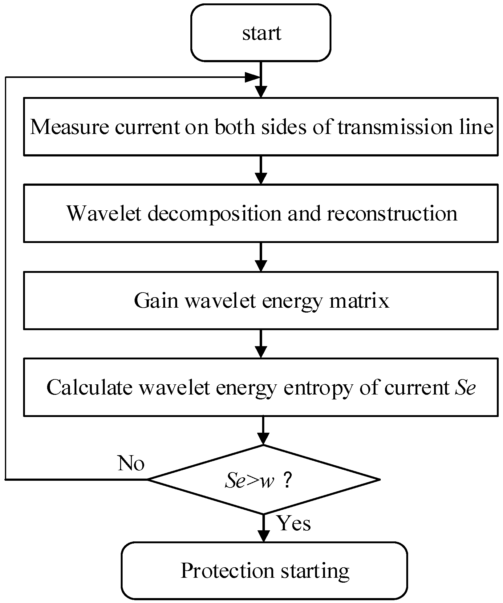
In this section, the starting criterion and protection criterion based on wavelet entropy of current and voltage are used for fault detection and HVDC transmission line protection. The following strategy is carried out according to the schemes in
Figure 6 and
Figure 7. Signals are acquired by simulation of the system in
Figure 1.
In order to evaluate the proposed method, the main characteristics concerning wavelet energy entropy and relative wavelet energy entropy, which are assessed in the frequency domain and time domain via wavelet transform, are discussed. For instance, monopole grounding faults, two-pole faults and different kinds of external fault are simulated with different resistance faults. Then, wavelet energy entropy is applied using a sliding window with length of 20 samples.
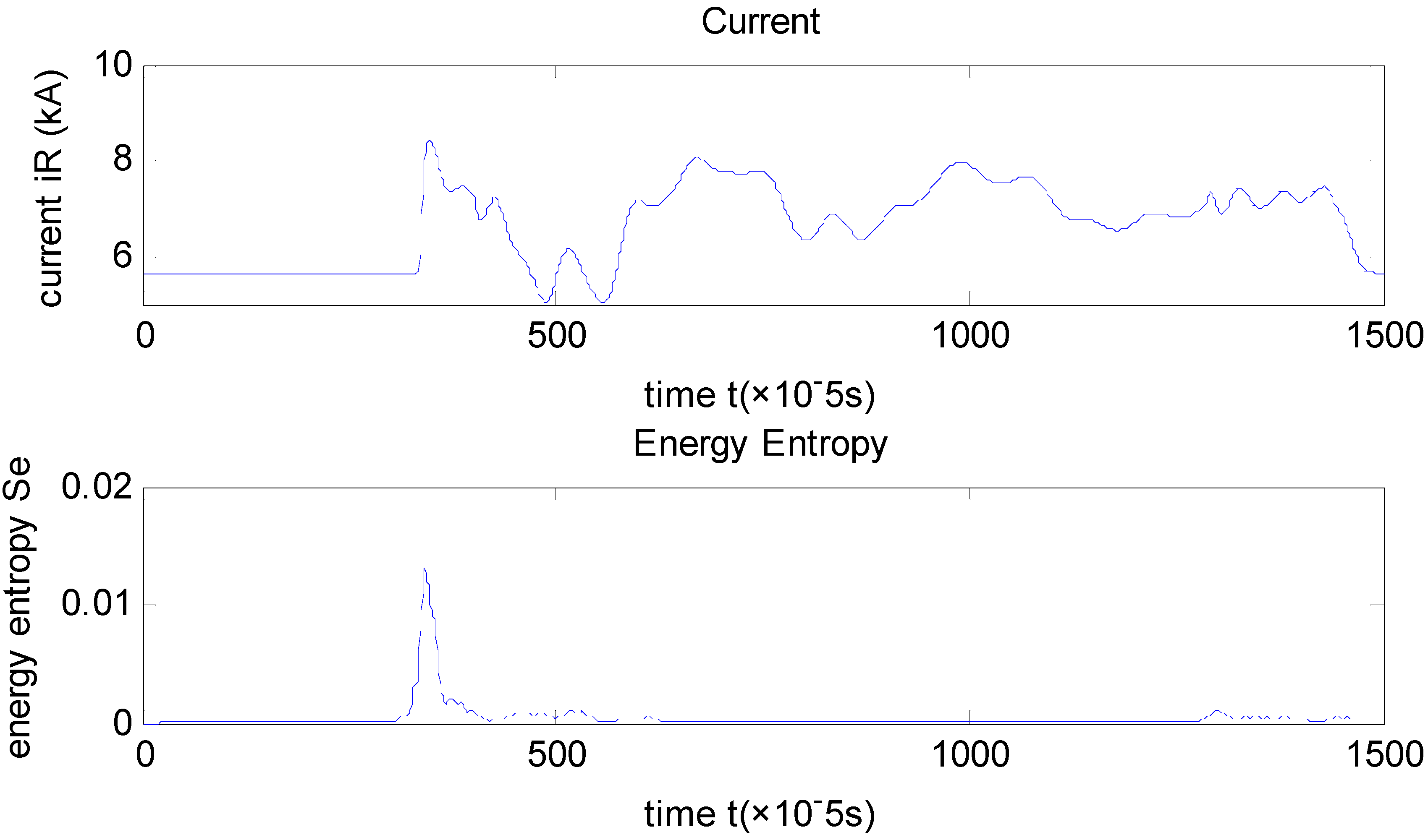
Figure 8,
Figure 9 and
Figure 10 show the obtained results for fault detection.
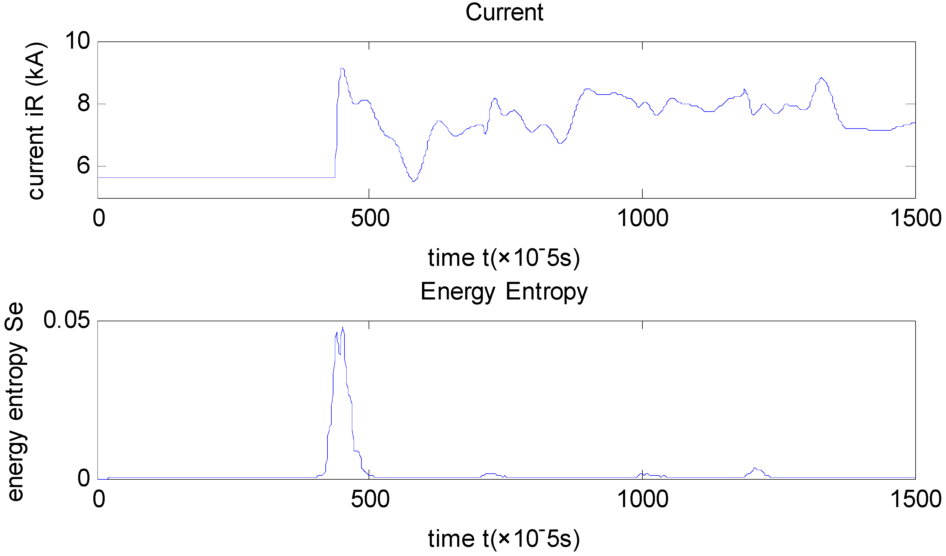
Figure 8 shows the transient behavior of current at rectifier-side, and the wavelet energy entropy computation under positive polar grounding fault with fault resistance R
f = 0.1Ω and fault distance at 100 km.
Figure 8.
Transient behavior of current signal measured at rectifier-side of energy entropy under monopole fault with fault resistance Rf = 0.1 Ω and fault distance at 100 km.
Figure 8.
Transient behavior of current signal measured at rectifier-side of energy entropy under monopole fault with fault resistance Rf = 0.1 Ω and fault distance at 100 km.
Figure 9 depicts results for a two-pole fault with fault resistance R
f = 100 and fault distance at 400 km.
Figure 10 illustrates results for an external fault at the rectifier-side. Results show clearly the detection time for all fault types that are tested. Thus, the proposed starting criterion only uses the wavelet energy entropy of the currents, concluding that the starting criterion is an effective algorithm for fault detection and protection startup, since the WEE detects any fault type reliably and rapidly and improves the detection time under fault conditions.
Figure 9.
Transient behavior of current signal measured at rectifier-side of energy entropy under two-pole fault with fault resistance Rf = 100 Ω and fault distance at 400 km.
Figure 9.
Transient behavior of current signal measured at rectifier-side of energy entropy under two-pole fault with fault resistance Rf = 100 Ω and fault distance at 400 km.
Figure 10.
Transient behavior of current signal measured at rectifier-side of energy entropy under external fault at inverter-side.
Figure 10.
Transient behavior of current signal measured at rectifier-side of energy entropy under external fault at inverter-side.
The starting criterion is carried out via energy entropy while the protection criterion is carried out via relative entropy of wavelet energy, and it is extensively assessed by simulations using multiple cases. These cases are simulated at the same inception time 0.35 s while varying in fault distance, fault impedance for each fault and noise level for each signal.
Simulations are conducted under the conditions that fault occurs at 0.35 s and fault distances of 1, 100, 750, 1490, and 1499 km for different types of fault with signal-noise ratio of 30 dB. The starting criterion realizes fault detection and determine the inception time of fault diagnosis.
Table 1 displays the results of fault diagnosis considering the fault distance, fault resistance, fault types and noise level.
Table 1.
Inception time of different types of fault determined by the starting criterion.
Table 1.
Inception time of different types of fault determined by the starting criterion.
| Fault position | Inception time (s) |
|---|
| Current measured at R Ir | Current measured at I Ii |
|---|
| F1 | 1km | 0.34846 | 0.35505 |
| 750km | 0.34999 | 0.35248 |
| 1499km | 0.35505 | 0.34975 |
| F2 | 1km | 0.35007 | 0.35505 |
| 750km | 0.35249 | 0.35199 |
| 1499km | 0.35504 | 0.34737 |
| F3 | 1km | 0.34796 | 0.35490 |
| 750km | 0.34839 | 0.35242 |
| 1499km | 0.35194 | 0.34978 |
| F4 | Rectifier-side | 0.35245 | 0.35840 |
| Inverter-side | 0.34861 | 0.35182 |
| F5 | A phase grounding fault at rectifier-side | 0.35185 | 0.35889 |
| A phase grounding fault at inverter-side | 0.35104 | 0.35018 |
Besides, fault resistances of 0.1, 100, and 1000 Ω for different types of fault with signal-noise ratio of 30 dB are simulated. The increasing values of grounding resistance indicate the decline of current, but the abovementioned feature doesn’t change so the protection system can still start.
To classify a detected fault, a 5 ms time window after detection is used for computing the relative wavelet energy entropy. For instance, in
Table 2 the results of different kinds of fault conditions with different fault distances are presented. Protection is carried out using the procedure summarized in
Figure 7. If a monopole grounding fault occurs at 1 km (when its fault resistance is 0Ω), the wavelet energy relative entropy of voltage and current fault component at the rectifier-side is 0.1415, and that at the inverter-side it is 2.775 × 10⁻³. These computations are used to follow the protection principle and it can be seen that
, so an internal fault took place and the protection relay should operate. The same process is followed for each simulation case.
Table 3 displays the results of different kinds of fault conditions with a noise level of 30 dB. In accordance to the attained results the relative entropy of wavelet energy can recognize internal fault regardless of fault position, fault resistance and noise level.
Table 2.
Results for different fault types with different fault positions (no noise).
Table 2.
Results for different fault types with different fault positions (no noise).
| Fault position | Fault distance | MR | MI | MR/MI | Result |
|---|
| F1 | 1 | 0.1415 | 2.775 × 10⁻³ | 50.99 | 1 |
| 100 | 0.1154 | 4.426 × 10⁻³ | 15.22 | 1 |
| 750 | 8.689 × 10⁻³ | 9.68 × 10⁻⁴ | 21.0730 | 1 |
| 1490 | 2.81 × 10⁻² | 5.049 × 10⁻³ | 5.565 | 1 |
| 1499 | 4.774 × 10⁻² | 1.37 × 10⁻² | 3.485 | 1 |
| F2 | 1 | 0.1978 | 4.784 × 10⁻³ | 41.35 | 1 |
| 100 | 0.1036 | 4.066 × 10⁻³ | 25.48 | 1 |
| 750 | 8.503 × 10⁻³ | 8.691 × 10⁻⁴ | 9.784 | 1 |
| 1490 | 2.854 × 10⁻² | 4.681 × 10⁻³ | 6.097 | 1 |
| 1499 | 4.911 × 10⁻² | 1.311 × 10⁻² | 3.746 | 1 |
| F3 | 1 | 0.1672 | 5.442 × 10⁻³ | 30.72 | 1 |
| 100 | 8.187 × 10⁻² | 4.899 × 10⁻³ | 16.72 | 1 |
| 750 | 2.541 × 10⁻² | 4.359 × 10⁻⁴ | 58.28 | 1 |
| 1490 | 3.272 × 10⁻² | 4.063 × 10⁻⁴ | 80.53 | 1 |
| 1499 | 1.196 × 10⁻³ | 7.27 × 10⁻⁵ | 16.45 | 1 |
| F4: Rectifier-side | - | 9.18 × 10⁻⁵ | 1.098 × 10⁻² | 8.361×10⁻³ | 0 |
| F4: Inverter-side | - | 1.189 × 10⁻² | 8.821 × 10⁻³ | 1.348 | 0 |
| F5: A phase grounding fault at rectifier-side | - | 3.334 × 10⁻³ | 2.196 × 10⁻³ | 1.518 | 0 |
| F5: A phase grounding fault at inverter-side | - | 3.695 × 10⁻⁴ | 8.847 × 10⁻³ | 4.177×10⁻² | 0 |
Table 3.
Results for different fault types with different fault positions (when noise level is 30dB).
Table 3.
Results for different fault types with different fault positions (when noise level is 30dB).
| Fault position | Fault distance | MR | MI | MR/MI | Result |
|---|
| F1 | 1 | 0.2862 | 1.924 × 10⁻³ | 148.8 | 1 |
| 100 | 0.201 | 8.089 × 10⁻³ | 24.85 | 1 |
| 750 | 6.591 × 10⁻² | 1.998 × 10⁻³ | 32.99 | 1 |
| 1490 | 9.689 × 10⁻² | 2.289 × 10⁻² | 4.233 | 1 |
| 1499 | 4.352 × 10⁻² | 1.077 × 10⁻² | 4.041 | 1 |
| F2 | 1 | 0.2658 | 9.927 × 10⁻³ | 26.78 | 1 |
| 100 | 0.2778 | 1.837 × 10⁻² | 15.12 | 1 |
| 750 | 8.811 × 10⁻² | 3.234 × 10⁻³ | 27.24 | 1 |
| 1490 | 3.452 × 10⁻² | 8.516 × 10⁻³ | 4.0535 | 1 |
| 1499 | 2.587 × 10⁻² | 7.54 × 10⁻³ | 3.431 | 1 |
| F3 | 1 | 0.3986 | 7.863 × 10⁻³ | 50.69 | 1 |
| 100 | 0.1421 | 1.251 × 10⁻² | 11.36 | 1 |
| 750 | 5.593 × 10⁻² | 2.768 × 10⁻⁴ | 556.5 | 1 |
| 1490 | 4.011 × 10⁻² | 9.645 × 10⁻³ | 4.159 | 1 |
| 1499 | 6.458 × 10⁻² | 2.258 × 10⁻³ | 28.6 | 1 |
| F4: Rectifier-side | - | 1.506 × 10⁻² | 1.743 × 10⁻² | 0.8640 | 0 |
| F4: Inverter-side | - | 3.895 × 10⁻² | 8.371 × 10⁻² | 0.4653 | 0 |
| F5: A phase grounding fault at rectifier-side | - | 6.685 × 10⁻³ | 3.885 × 10⁻³ | 1.721 | 0 |
| F5: A phase grounding fault at inverter-side | - | 5.549 × 10⁻² | 8.427 × 10⁻² | 0.6585 | 0 |
Table 4.
Results for internal fault with different fault resistance.
Table 4.
Results for internal fault with different fault resistance.
| Fault position | Fault resistance | MR | MI | MR/MI | Result |
|---|
| F1 100 km | 0.1 | 0.1154 | 4.426 × 10⁻³ | 26.07 | 1 |
| 100 | 0.1008 | 6.281 × 10⁻³ | 16.05 | 1 |
| 1000 | 0.1059 | 5.8 × 10⁻³ | 18.26 | 1 |
| F2 750 km | 0.1 | 8.503 × 10⁻³ | 8.691 × 10⁻⁴ | 9.784 | 1 |
| 100 | 7.74 × 10⁻³ | 7.247 × 10⁻⁴ | 10.68 | 1 |
| 1000 | 1.193 × 10⁻² | 8.587 × 10⁻⁶ | 1389 | 1 |
| F3 1499 km | 0.1 | 1.196 × 10⁻³ | 7.27 × 10⁻⁵ | 16.45 | 1 |
| 100 | 3.952 × 10⁻² | 4.126 × 10⁻³ | 9.578 | 1 |
| 1000 | 3.184 × 10⁻² | 9.997 × 10⁻³ | 3.185 | 1 |


