1. Introduction
Gas turbines are used successfully to power aircraft as well as to generate power in industrial applications. In offshore marine platforms, gas turbines are used as stationary power plants or as prime mover of pumps and compressors, because they are compacts with low weigh and reliable operation. There exist aero-derivate gas turbines of low and medium power, and their maximum capacity of generation is of 65 MW, depending on their compressor pressure ratio, high pressure turbine inlet temperature and of their shaft number [
1,
2]. In addition, the performance of the delivered power of a gas turbine is affected by the conditions presented at the place where it is installed, mainly ambient temperature, atmospheric pressure and the air relative humidity [
3].
A two-shaft aero-derivate gas turbine is composed by a gas generator and a free power turbine also known as a low pressure turbine. The gas generator consists of a compressor, a combustion chamber and a high pressure turbine. The gas generator turbine provides power for the air compressor and the free power turbine generates the useful power output. Likewise, improvements in the design and operation of gas turbines have come along with advances in aerodynamics, thermodynamics and metallurgy has made possible for today’s gas turbines to withstand temperatures in the 1415 °C range, compressor pressure ratios up to 34:1 and overall thermal efficiency up to 42% [
4,
5].
However, as the gas turbines present large losses energetics and economics in spite of the technologic development, Bejan [
6] has development a useful tool that supply information about performance of conversion systems of energy, and it gives the possible upgrade of the devices, supporting with a parametric analyses. The first law of thermodynamic is the principal tool to do thermodynamic analyses, but it only give responses about of thermal efficiency of the cycle and doesn’t provide the irreversibilities of each of components of the system. Along with the exergetic analyses, the quality of the energy and the irreversibilities of each of the components of the system can also be assessed. The exergetic analysis use the mass and energy balances and the second law of thermodynamics to do the analysis, design and the improvement of the energetic systems; moreover, it identifies the types and magnitude of the wastes, losses, and efficiencies of system to establish the potential of improvement of energy systems [
6,
7,
8,
9].
The literature presents several works about thermodynamics analyses of gas turbines, but most are focused to study the performance of simple gas turbines or power plants of cycle combined [
10,
11,
12,
13,
14,
15,
16,
17]. Nevertheless, most works only study one condition of operation, with the exception of [
3], which establishes that the turbine inlet temperature, the drops of pressure, environmental temperature and compressor pressure ratio are parameters that change the thermal efficiency of gas turbines.
Hakan Aydin [
1,
2] presents an exergetic study of an aero-derivate gas turbine LM6000, Hakan reports an exergetic efficiency of 39% for a compressor pressure ratio of 30 and a power of 43 MW. He has reported that the value of irreversibilities in the combustion chamber is 25.91 MW; it represents 60% of the generated power and its exergetic efficiency is 85.1%, considering a drop of pressure of 5%. However, it is not possible to do a comparison that only presents the analysis for a condition of operation. He also presents that the destruction of exergy of the turbine of gas generator is bigger than free power turbine. Nevertheless, he doesn’t establish that the aero-derivate gas turbine has a system of Nozzle Guide Vane (NGV) and that it increases the high pressure turbine inlet temperature.
The aim of this work is to present a methodology based on the exergetic analysis to estimate irrevesibilities and exergetic efficiencies of each of the main components of an aero-derivate gas turbine. The studied engine is the Mars 100, an aeroderivative gas turbine with two-shaft design and rated to provide 11.86 MW. In this engine, the air is compressed in an axial compressor achieving a pressure ratio of 17.7 relative to ambient conditions and a high pressure turbine inlet temperature of 1220 °C. The compressor and turbine efficiencies are assumed to be 0.85 and 0.80, respectively.
2. Methodology
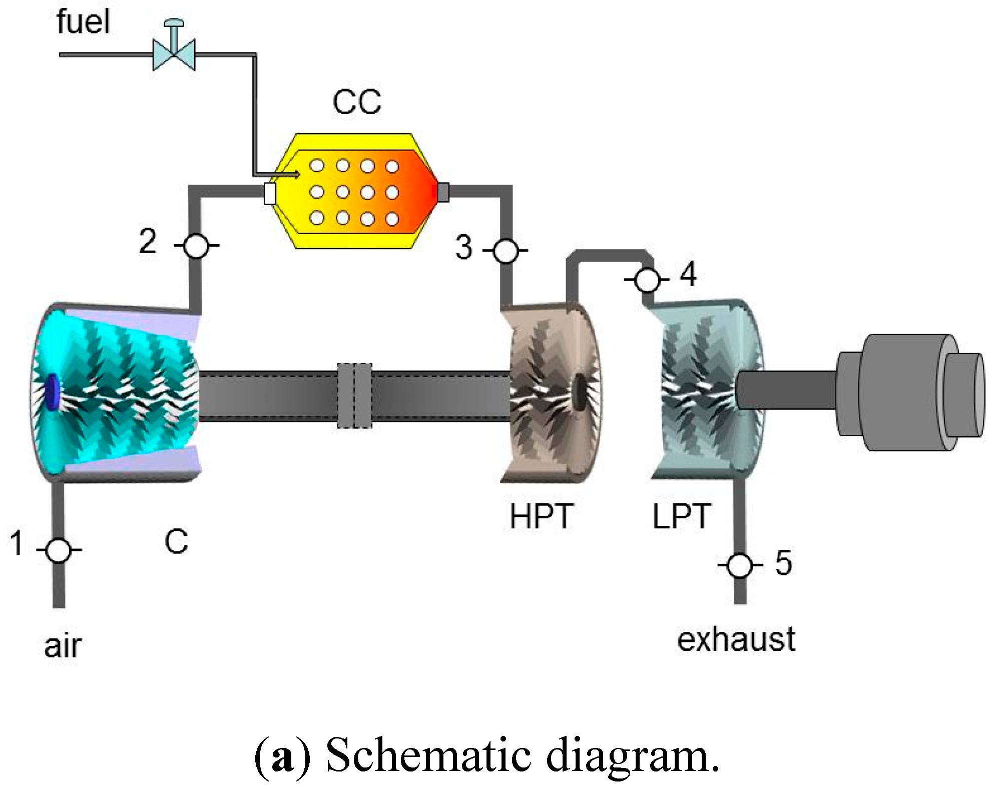
A two-shaft aeroderivate gas turbine is conformed by a gas generator and a free power turbine also known as low pressure turbine (LPT), as depicted in the schematic diagram of
Figure 1a. The gas generator consists of a compressor, a combustion chamber and a high pressure turbine (HPT). An aeroderivative gas turbine operates on the thermodynamic cycle presented in the temperature-entropy diagram of
Figure 1b, in which air entering the compressor at state 1 is compressed to some higher pressure and temperature at state 2. Leaving the compressor, air enters the combustion chamber, where combustion occurs by fuel injection. In the combustion process, a pressure drop occurs by the mixing, burning and cooling phenomena. The exhaust gases leave the combustion system and enter the HPT at state 3. In the HPT of the gas generator, the hot gases are expanded to state 4 and their thermal energy is converted into work, which is used to drive the compressor of the gas generator. The expanded gases at state 4 enters the LPT coupled aerodynamically to the gas generator, where they are expanded to state 5, at a pressure higher than the air pressure at state 1 to generate the useful power output.
Figure 1.
Two-shaft gas turbine.
Figure 1.
Two-shaft gas turbine.
In this work, the development of a systematic methodology is pursued to evaluate the performance of the Mars 100 gas turbine, based on the estimation of the engine component irreversibilities. The Solar Mars 100 is an aeroderivative two-shaft gas turbine rated to provide a Standard conditions base load of 11.86 MW and designed especially for mechanical drive applications. Its main components are a 15-stage axial-flow air compressor with a compression ratio of 17.7:1, an annular combustion chamber, a two-stage reaction HPT and a two-stage axial flow LPT. Since the engine summary screen of the Mars 100 only reports pressures and temperatures at the states one, two and five, a parametric analysis of the gas turbine performance becomes relevant, taking the compressor pressure ratio and the HPT inlet temperature T4, as the main parameters, whose studied values are taken from the manufacturer operational recommendations. This analysis considers the existence of pressure drops in the combustion chamber as well as in the LPT and is carried out for compressor and turbine isoentropic efficiencies of 0.85 and 0.80, respectively.
The compressor pressure ratio is the relation between the compressor discharge pressure,
P2, and the compressor suction pressure,
P1,
For the actual compression process, the specific input compression work is
The compression work, given by Equation (1), is a function of the environmental parameter T1, and the technological parameters and .
The increase of entropy for a compression process can be obtained from the following expression
In the combustion process, a pressure drop of 5% in considered, and the amount of heat transferred to the air at constant pressure is a function of the temperatures ratio
, this relation involves an environmental and technological conditions. The technological temperature
is constrained by the technological development of the material gas turbine, while
is constrained by the variations in the environmental conditions.
The entropy change in the heating process is given by
The compressor work is provided by the work generated by the HPT, and the losses due to the transmission of work from turbine to compressor are determined by introducing the mechanical efficiency of
.
The outlet temperature of the HPT can be expressed in terms of
, as follows
The expression of the HPT pressure ratio in terms of the temperature ratio
is given by
For an expansion process the change in entropy can be expressed as
The unknown temperature and pressure at state four,
T4 and
P4, can be found from the LPT pressure ratio, π
LPT; and the useful output specific work generated by the power turbine can then be written as follows
The change in entropy for the expansion process in the LPT is given by
The thermal efficiency is the relation between the actual work delivered by the free power turbine and the supplied heat by the fuel combustion,
The air flow rate required to generate a demanded power output can be then expressed as
The fuel flow fuel is given by
By definition, the heat rate (HR) is the energy required to generate one kW-h, and its expression is given by:
3. Exergetic Analysis
Exergy analysis is based on the second law of thermodynamics. This analysis is an essential tool to provide insights of the performance of energy conversion systems, and highlights the possible improvements. The exergy analysis has been extending to many applications, considering also some energetic, economic, and environmental factors [
6,
7,
8]. The exergy is then a powerful tool for understanding and improving the sustainability of processes and systems.
The exergy of a heat transfer process for a given control surface is determined from the maximum work that could be obtained from it using the environment as a reservoir of zero grade thermal energy [
7]. For a heat transfer rate
and a temperature at the control surface where the heat transfer is taking place
Tr, the maximum rate of conversion from thermal energy to work is
where
is the dimensionless exergetic temperature and is equal to the Carnot coefficient when the environment at
T0 is used as the other thermal energy reservoir, and it can be expressed as
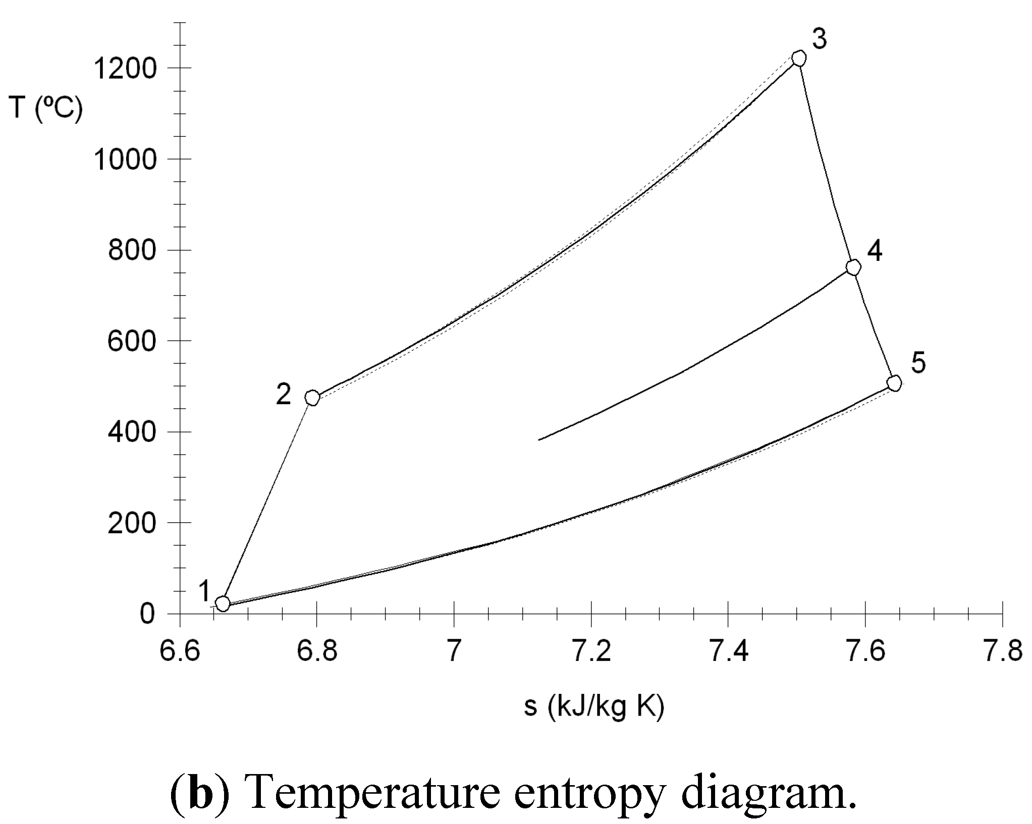
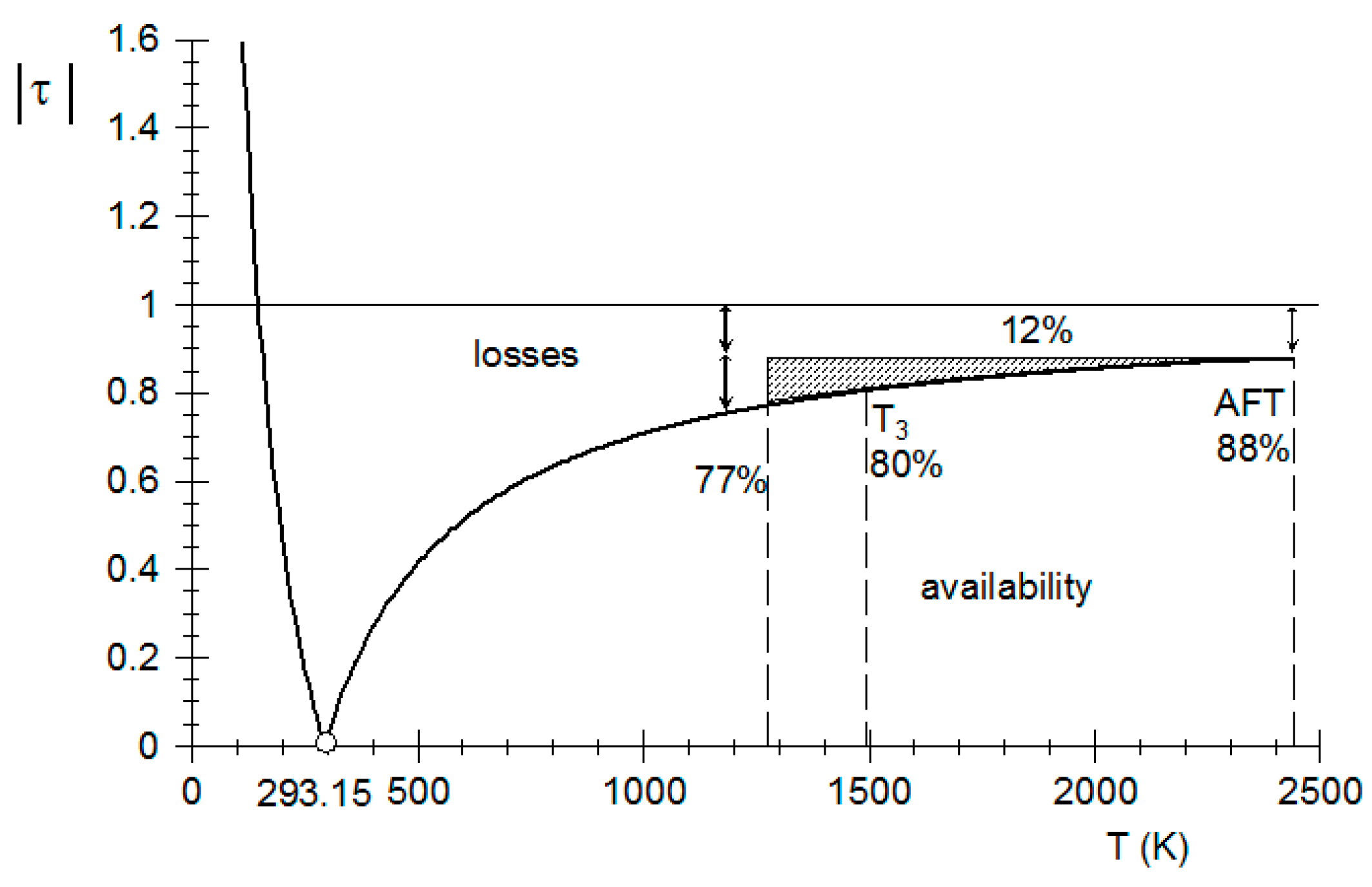
The Carnot coefficient in terms of the combustion temperature is presented in
Figure 2, and this figure shows that the maximum work is approximately 88% considering the adiabatic flame temperature for natural gas as fuel. The losses due to the combustion process are approximately 12%; nevertheless the combustion gas temperature decreases for a high pressure turbine inlet temperature of the gas turbine Mars 100 of 1200 °C, leading to an additional loss of 8%, due to the cooling of the combustion gases, and these losses increase with the decreasing of
T3.
Figure 2.
Exergetic temperature factor.
Figure 2.
Exergetic temperature factor.
In order to obtain the specific physical exergy of the thermodynamic states of the aeroderivate gas turbine, the following expression is used:
The specific physical exergy for air and combustion gases with constant specific heat is obtained from:
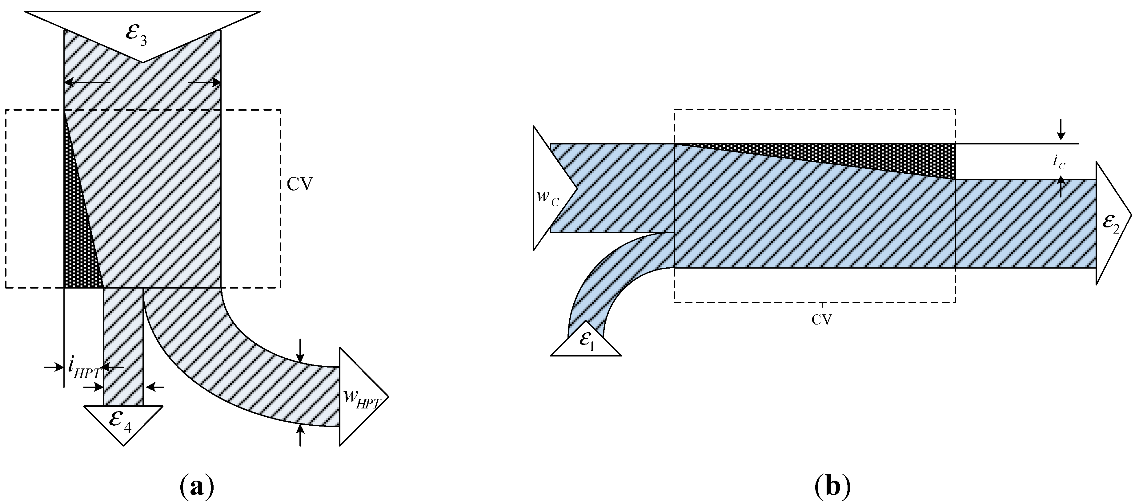
Figure 3a,b present the control volumes of the expansion and compression processes. These figures show the exergies, works and irreversibilities of the inlets and outlets of the control volumes. The exergetic balances for the control volumes of compression and expansion processes are given by:
Figure 3.
(a) Expansion process and (b) compression process.
Figure 3.
(a) Expansion process and (b) compression process.
3.1. Gas Turbine
The exergetic efficiency of the high pressure turbine in terms of the irreversibility and turbine efficiency is given by
where r
HPT, is the frictional reheat, which is defined as
.
3.2. Compressor
The exergy balance for the compressor can be written as:
The exergetic efficiency of the compressor in terms of the irreversibility and compressor efficiency results as follows
where, r
C is the frictional reheat of the compression process, which is defines as
.
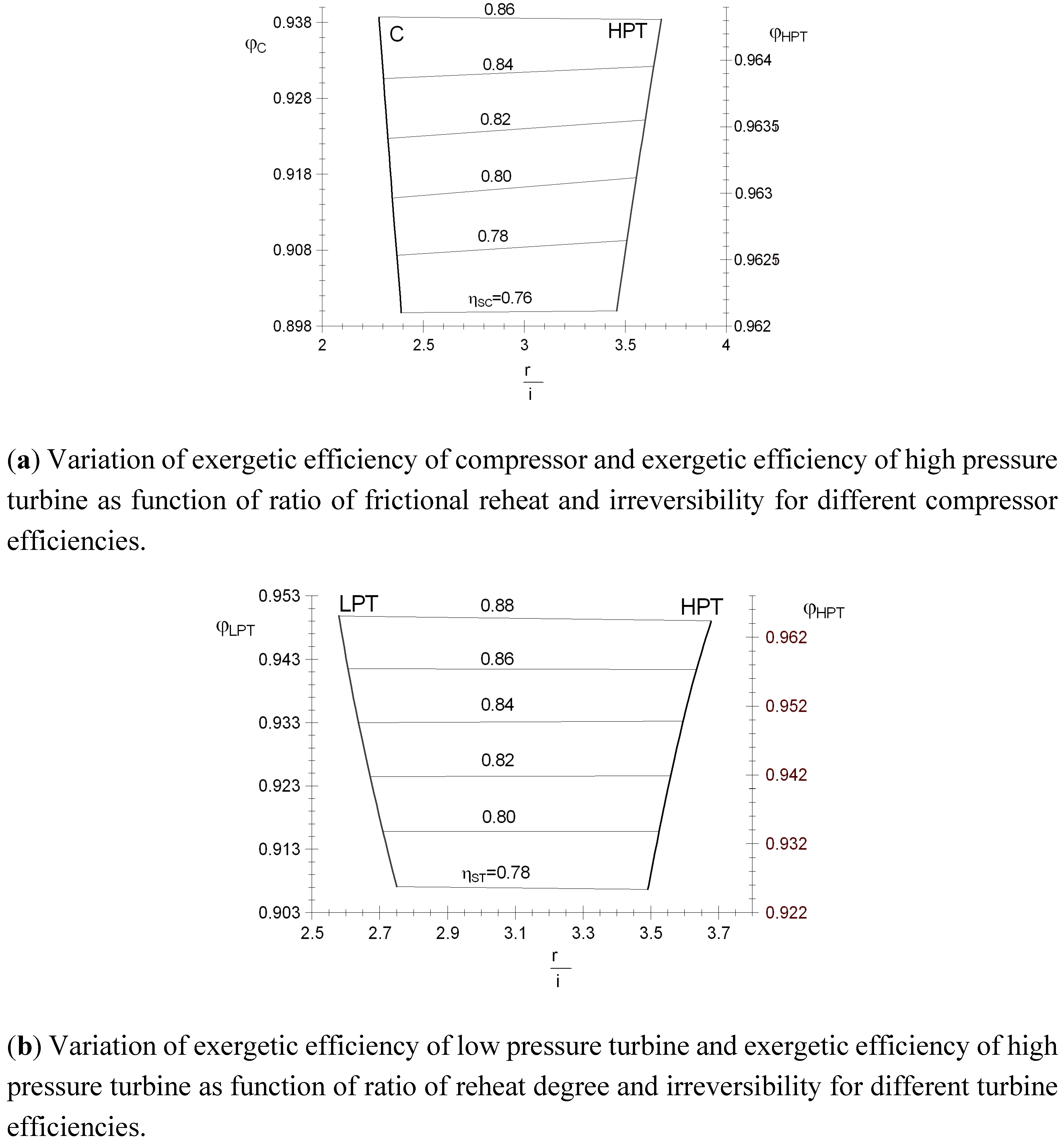
Figure 4a presents the variations of the exergetic efficiencies of the compressor and high pressure turbine as a function of the ratio of frictional reheat and irreversibility for different values of the compressor efficiencies. The results show that the r
C/i
C increases as the compressor efficiency decreases due the increase of the irreversibilities in the compressor and the frictional reheat; likewise, by decreasing the compressor efficiencies and also decreasing r
HPT/i
HPT, since the increase of the irreversibilities is higher than the increase the frictional reheat. For a compressor efficiency of 0.86, the value of r
C/i
C is of 2.27 and the value exergetic efficiency of the compressor of 0.938. Indeed, a 0.84% reduction in the compressor efficiency can be observed that the r
C/i
C is increased 0.98%, due that the frictional reheat increase 17.01% and the irreversibilities only 15.8%; nevertheless, the exergetic efficiency of the high pressure turbine is not affected in great measure. As result of an increase of 7% of the irreversibilities in the high pressure turbine, the r
HPT/i
HPT decreases 1.1%.
Figure 4b presents the variations of the exergetic efficiencies of low and high pressure turbines as function of r/i for different values of the turbine efficiency. The results show that the r
LPT/i
LPT increases as the compressor efficiency decreases due to the increase of the irreversibilities in the low pressure turbine and the frictional reheat; likewise, by decreasing the turbine efficiencies and also decreasing r
HPT/i
HPT, since the increase of the irreversibilities (i
HPT) is higher than the increase the frictional reheat (r
HPT). For a turbine efficiency of 88%, the value of r
LPT/i
LPT is of 2.5795 and the value exergetic efficiency of the low pressure turbine of 0.9498. Indeed, reducing the turbine efficiency from 88% to 86% the r
LPT/i
LPT increases 1.07%, due that the frictional reheat increase 13.98% and the irreversibilities 12.77%. Nevertheless, the exergetic efficiency of the high pressure turbine decreases 0.73% and the r
HPT/i
HPT decreases 1.209%, a result of the increase of 20.84% in the irreversibility in the high pressure turbine.
Figure 4.
Variation of exergetic efficiencies of compressor and low and high pressure turbines as function of ratio of reheat degree and irreversibility for different compressor and turbine efficiencies.
Figure 4.
Variation of exergetic efficiencies of compressor and low and high pressure turbines as function of ratio of reheat degree and irreversibility for different compressor and turbine efficiencies.
In this analysis, it is supposed that the combustion process is adiabatic, and the irreversibilities due to the friction and the mixed are negligible.
The exergy balance for the combustion chamber is the following:
The exergy delivered by the fuel to the adiabatic flame temperature, (
), it can be expressed as
The exergetic efficiency of the combustion is given by
where
is negative, due to the amount of the Gibbs free energy.
It will perform a parameter study to determine how the system performance varies with different operating parameters.
Table 1 shows the mathematic models to assess the work, supplied heat, irreversibilities, and exergetic efficiencies of the engine components.
Table 1.
Work, supplied heat, irreversilities and exergetic efficiencies of the engine components.
Table 1.
Work, supplied heat, irreversilities and exergetic efficiencies of the engine components.
| Engine Components | Energy | Irreversibility | Exergetic Efficiency |
|---|
| Compressor | | | |
| Combustion chamber | | | |
| High pressure turbine | | | |
| Low pressure turbine | | | |
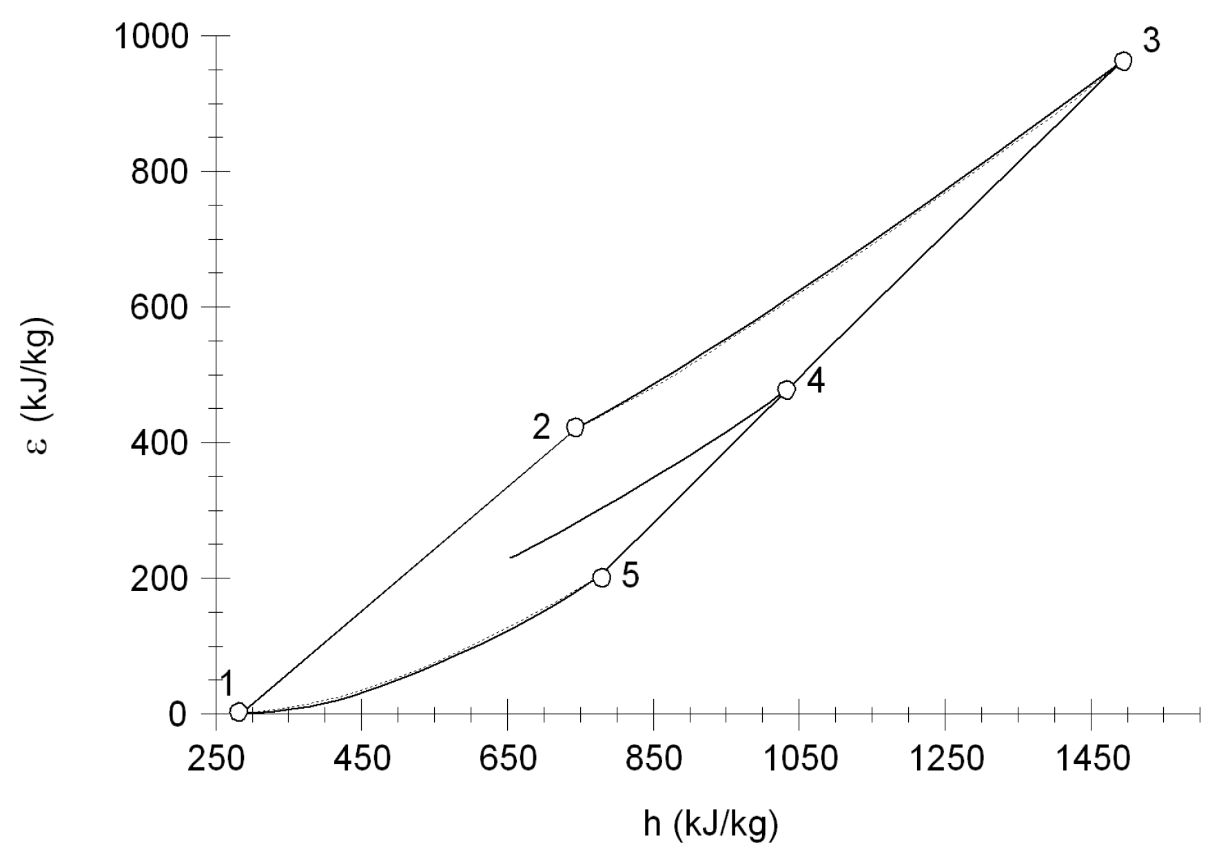
Figure 5 shows the diagram exergy-enthalpy. It presents the thermodynamic states of aeroderivate gas turbine. State three has the maximum exergy because it has the higher temperature and pressure of the system. The difference of enthalpies of the high pressure turbine is higher than the difference of enthalpies of the compressor by 2% due to the mechanical losses in the shaft. However, the difference of exergies of the high pressure turbine is 483.77 kJ/kg and the difference of exergies of the compressor of 421.32 kJ/kg. Then, the difference is 13%, 2% are for the mechanical losses in the shaft and 11% by internal irreversibilities in the high pressure turbine.
Figure 5.
Exergy enthalpy diagram of a two-shaft aero-derivate gas turbine.
Figure 5.
Exergy enthalpy diagram of a two-shaft aero-derivate gas turbine.
4. Results and Discussion
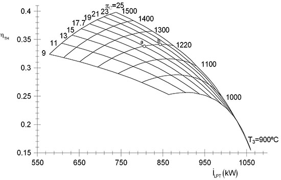
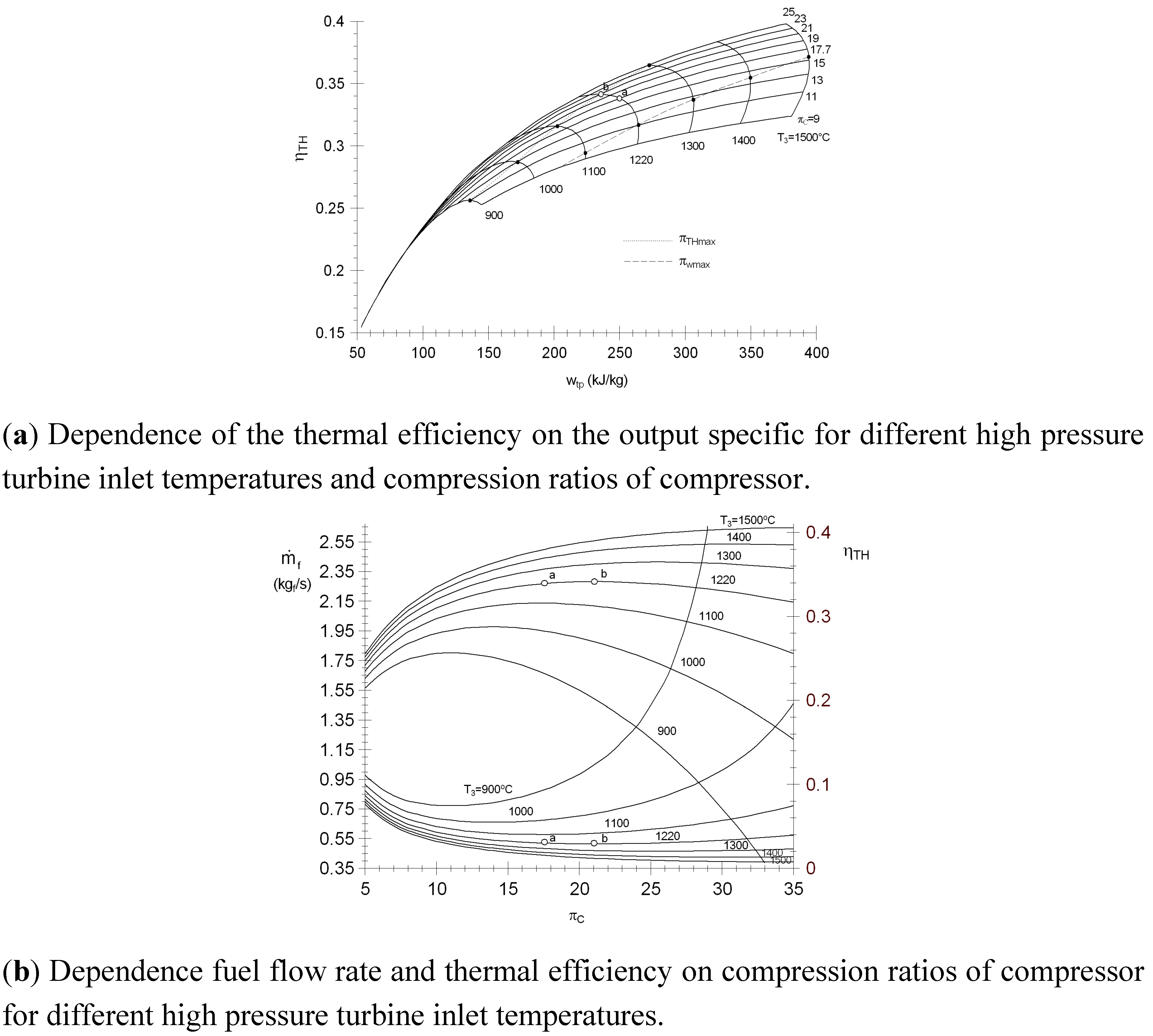
Figure 6a shows the thermal efficiency as a function of work output specific for different values of high pressure turbine inlet temperature and different values of pressure ratios of the compressor. For a high pressure turbine inlet temperature of 1220 °C, the pressure ratio of the compressor to obtain the maximum thermal efficiency is 21 (point b). Nevertheless, the pressure ratio of the compressor of operation of turbine Mars 100 is 17.7 (point a), hence there is a depletion of 1% of the thermal efficiency and 15 kJ/kg of the specific work output. It shows that by decreasing the high pressure turbine inlet temperature 100 °C keeping constant pressure ratio, the specific work output decreases 48.33 kJ/kg and the thermal efficiency rises 2.24%.
Figure 6b shows the fuel flow rate and the thermal efficiency as a function of pressure ratio of compressor for different values of high pressure turbine inlet temperature. It must be noted that to generate 11.8 MW, the value pressure ratio that minimizes fuel flow rate is 21 (point b); nevertheless, the value pressure ratio of operation of turbine Mars 100 is 17.7 (point a), hence there is an increase of fuel flow rate of 1% (0.0078 kg
f/s) with respect to point b. It shows that by decreasing the high pressure turbine inlet temperature to 1100 °C keeping constant pressure ratio, the fuel flow rate increases to the 0.577 kg
f/s, supplying 10% more fuel to maintain the same power on Mars 100.
Figure 6.
Design performance charts for the two-shaft aero-derivate gas turbine.
Figure 6.
Design performance charts for the two-shaft aero-derivate gas turbine.
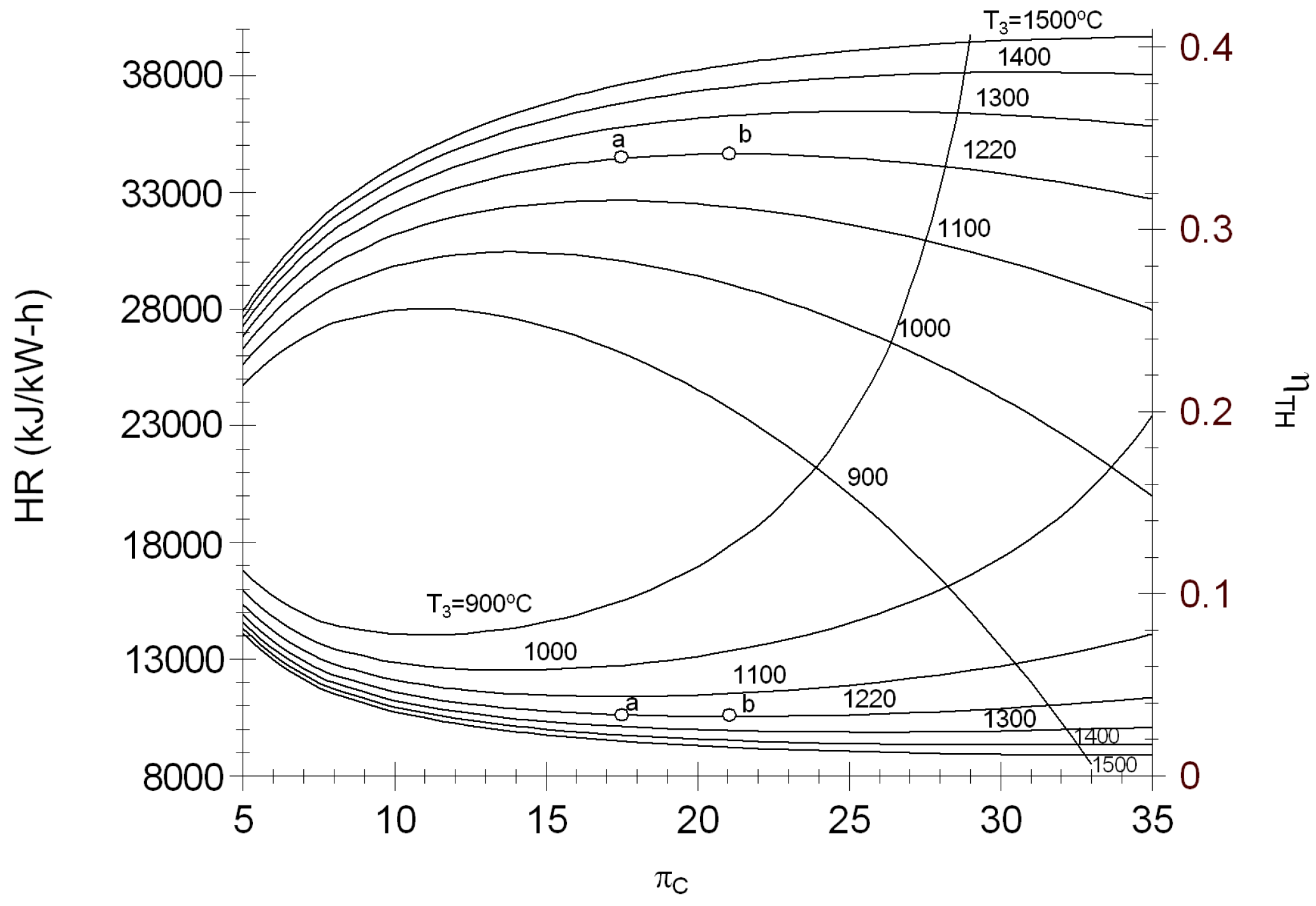
Figure 7 shows the effects the pressure ratio of the compressor on the heat rate and thermal efficiency for different values of the T
3. The behavior of the
Figure 7 is similar to the
Figure 6b due to the relationship that there is with the fuel. For the operation conditions of the turbine Mars 100, the heat rate is 12,200 kJ/kW-h (point a); with respect to π
C for maximum thermal efficiency (point b), there is a variation lower to 100 kJ/kW-h.
Figure 7.
Heat rate and thermal efficiency against compression ratio of compressor for different high pressure turbine inlet temperatures.
Figure 7.
Heat rate and thermal efficiency against compression ratio of compressor for different high pressure turbine inlet temperatures.
It is important to analyze the thermodynamic performance of the compressor in relation to the compressor efficiency, a drop of the η
SC effects to all components of derivate gas turbine, the results of the exergetic analysis are presented in
Table 2. From this table, an increment of
,
,
and
of 20.26%, 1,5%, 7.5% and 0.14%, respectively, and the exergetic efficiencies of the low and high pressure turbines decreases in 1%, as well as η
C decreases from 86% to 84% for a turbine efficiency of 85% can be observed. The heat transferred to the aeroderivate turbine increases 26.01% when the η
T decreases from 86% to 76% to generate an output of 11.86 MW.
It can be assumed that the turbine has been being operating for ten years and that the compressor efficiency has dropped from 86% to 76%. As a result, its exergetic efficiency decreases from 94% to 90% and the irreversilities of the high pressure turbine are increased 51.77%.
Table 2.
Variation of exergy of heat transfer, irreversibility rate and exergetic efficiencies of the aeroderivate gas turbine components as functions of the compressor efficiency for ηHPT = ηLPT = 0.85.
Table 2.
Variation of exergy of heat transfer, irreversibility rate and exergetic efficiencies of the aeroderivate gas turbine components as functions of the compressor efficiency for ηHPT = ηLPT = 0.85.
| ηC | (kW) | (kW) | (kW) | (kW) | (kW) | φC | φHPT | φLPT |
|---|
| 0.86 | 20,190.14 | 1,112.28 | 7,919.59 | 912.20 | 816.08 | 0.94 | 0.95 | 0.94 |
| 0.84 | 20,963.22 | 1,337.69 | 8,038.82 | 980.60 | 814.95 | 0.93 | 0.95 | 0.94 |
| 0.82 | 21,845.64 | 1,590.75 | 8,178.14 | 1,059.22 | 813.73 | 0.92 | 0.95 | 0.94 |
| 0.80 | 22,862.27 | 1,877.49 | 8,342.24 | 1,150.43 | 812.39 | 0.91 | 0.95 | 0.94 |
| 0.78 | 24,046.11 | 2,205.87 | 8,537.40 | 1,257.41 | 810.91 | 0.91 | 0.95 | 0.94 |
| 0.76 | 25,441.93 | 2,586.66 | 8,772.14 | 1,384.46 | 809.29 | 0.90 | 0.95 | 0.94 |
The change of the irreversibility rate as a function of the turbine efficiency is shown in
Table 3. From this table, an increment of
,
,
and
of 4.73%, 4.07%, 26.6% and 18.15%, respectively, and the exergetic efficiencies of the low and high pressure turbines decreases in 1%, as well as η
T decreases from 88% to 86% for a compressor efficiency of 80% can be observed. The heat transferred to the aeroderivate turbine is increased by 26.01% when the η
T decreases from 88% to 86% to generate an output of 11.86 MW.
It is assumed that the turbine has been operating for ten years and that the turbine efficiency has dropped from 88% until 85%. As a result, the exergetic efficiency decreases 1% and the irreversibility of the high pressure turbine increases 10%.
Table 3.
Change of the exergy rate of the heat transfer, irreversibilities rate and exergetic efficiencies of components of the aeroderivate gas turbine as functions of the turbine efficiency for ηC = 0.80.
Table 3.
Change of the exergy rate of the heat transfer, irreversibilities rate and exergetic efficiencies of components of the aeroderivate gas turbine as functions of the turbine efficiency for ηC = 0.80.
| ηT | (kW) | (kW) | (kW) | (kW) | (kW) | φC | φHPT | φLPT |
|---|
| 0.88 | 17,783.42 | 1,002.16 | 7,314.01 | 611.30 | 632.66 | 0.94 | 0.96 | 0.95 |
| 0.86 | 19,186.12 | 1,049.58 | 7,624.87 | 773.91 | 747.49 | 0.94 | 0.96 | 0.94 |
| 0.84 | 20,747.46 | 1,102.37 | 7,970.88 | 961.71 | 864.47 | 0.94 | 0.95 | 0.93 |
| 0.82 | 22,497.97 | 1,161.54 | 8,358.82 | 1,179.99 | 983.70 | 0.94 | 0.94 | 0.92 |
| 0.80 | 24,476.83 | 1,228.44 | 8,797.37 | 1,435.55 | 1,105.28 | 0.94 | 0.93 | 0.92 |
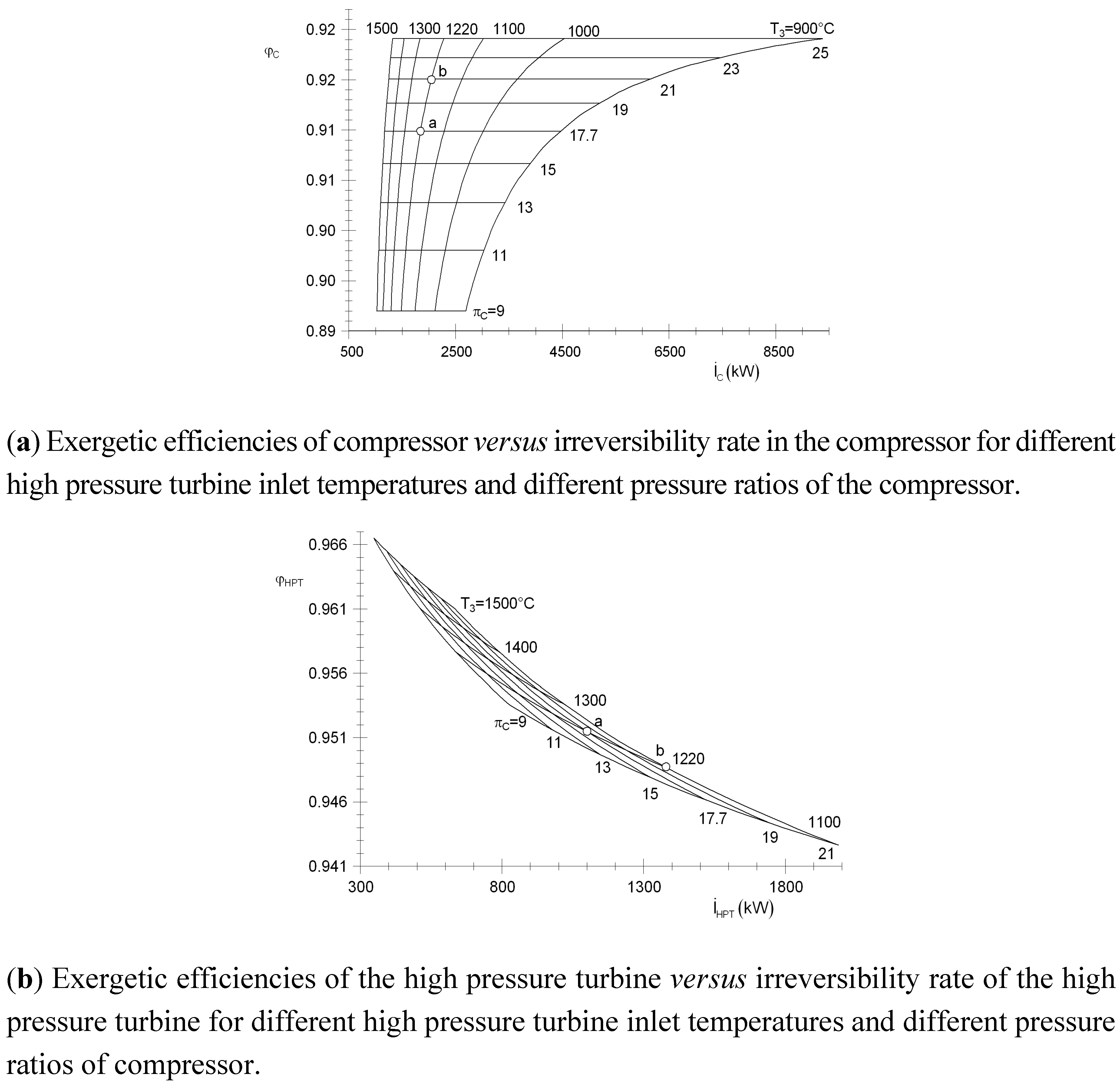
Figure 8a shows the exergetic efficiency of compressor as function of irreversibility rate in compressor for different high pressure turbine inlet temperatures and different pressure ratios of the compressor. This figure shows that by increasing the temperature inlet high pressure turbine, the irreversibility rates decrease. It presents that keeping constant the high pressure turbine inlet temperature and increasing the pressure ratio of compressor, the exergetic efficiency of the compressor and the irreversibilities rate in compressor are increased. Note, for instance, for the condition of point a, the exergetic efficiency is 91.7% and the irreversibility rate is 1842 kW; increasing the pressure ratio of compressor from 17.7 to 21 (point b), the exergetic efficiency and irreversibility rates are increased 1% and 4.58%, respectively.
Figure 8b shows the exergetic efficiency of high pressure turbine at different irreversibility rates in the high pressure turbine for different high pressure turbine inlet temperatures and different pressure ratios of the compressor. For a high pressure turbine inlet temperature of 1220 °C and a pressure ratio of compressor of 17.7 (point a), the exergetic efficiency high pressure turbine is 95.14%, and the irreversibility rate is 1084.26 kW. Note also that by increasing the high pressure turbine inlet temperature to 1500 °C, the exergetic efficiency is increased 1.11% and the irreversibility rate decreases to 532 kW.
The results displayed in
Figure 8a and
Figure 8b show that the exergetic efficiency of the high pressure turbine is higher than from the compressor, and the irreversibility rates of the high pressure turbine are lower than from the compressor.
Figure 8.
Exergetic efficiency of compressor and high pressure gas turbines on irreversibility rates for different high pressure turbine inlet temperatures and pressure ratios of the compressor.
Figure 8.
Exergetic efficiency of compressor and high pressure gas turbines on irreversibility rates for different high pressure turbine inlet temperatures and pressure ratios of the compressor.
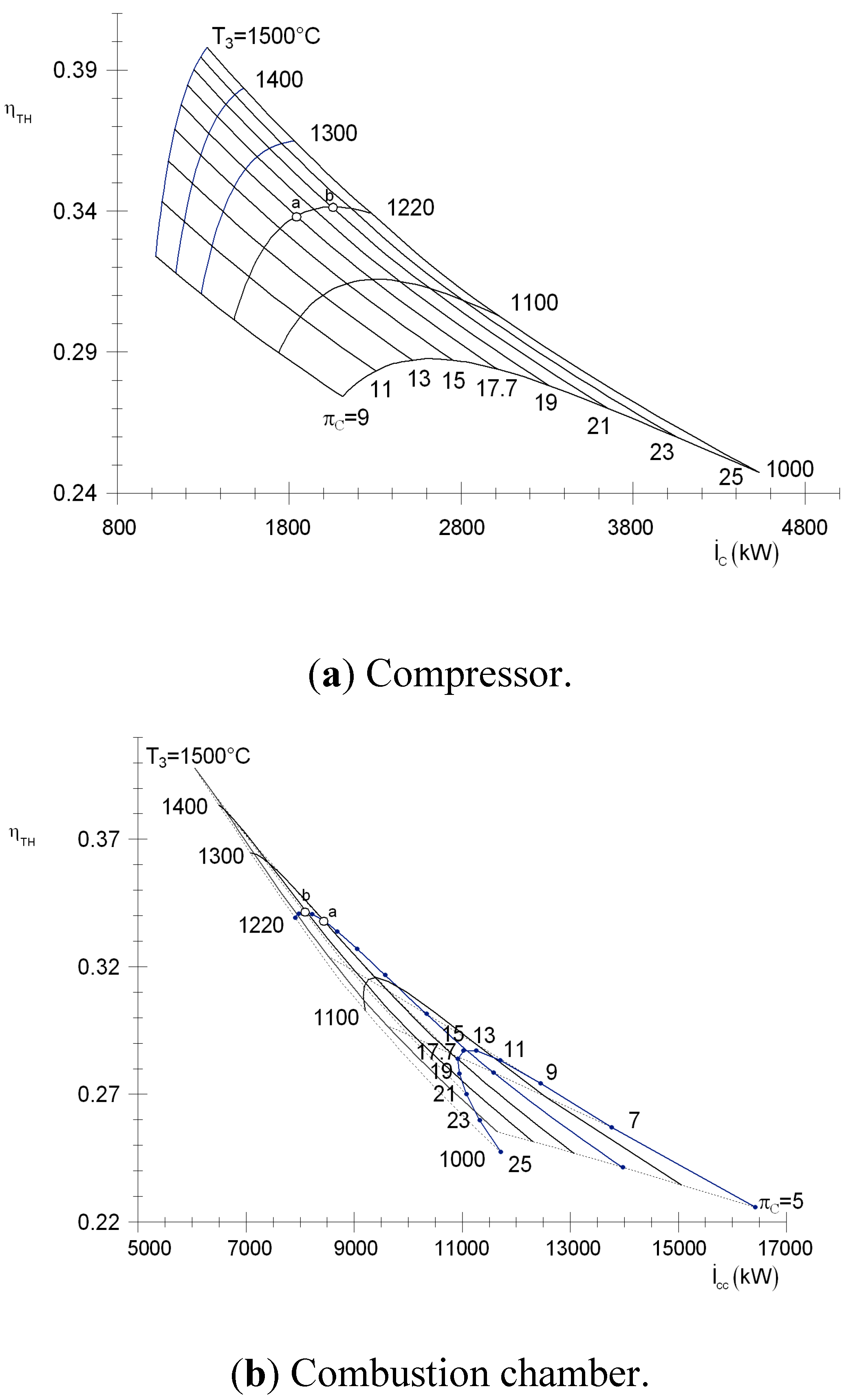
Figure 9a shows that by increasing the high pressure turbine inlet temperature and keeping a constant pressure ratio of the compressor, the thermal efficiency increases and the irreversibility rates in the compressor decreases. Note, for instance, that for 1220 °C and a pressure ratio of 17.7, the thermal efficiency is 34% and the irreversibility rates are 1847.17 kW; decreasing the temperature to 1100 °C and keeping constant the pressure ratio, the thermal efficiency is decreased 1.8%, and irreversibility rates increase 422.3 kJ/kg.
Figure 9b shows the thermal efficiency variation as a function of the irreversibility rates in combustion chamber for different high pressure turbine inlet temperatures and pressure ratios of the compressor. It clearly shows that for a high pressure turbine inlet temperature of 1220 °C and a compression ratio of 17.7 (point a), the thermal efficiency is 33.92% and the irreversibility rate is 8490.2 kW. Increasing the compression ratio to 21 (point b) and keeping the temperature constant, the thermal efficiency is increased to 34.22% and the irreversibility decreases 4.14%. In combustion chamber, larger losses in aeroderivate gas turbine are generated.
Figure 9.
Thermal efficiency on the irreversibility rate for different high pressure turbine inlet temperatures and pressure ratios of the compressor.
Figure 9.
Thermal efficiency on the irreversibility rate for different high pressure turbine inlet temperatures and pressure ratios of the compressor.
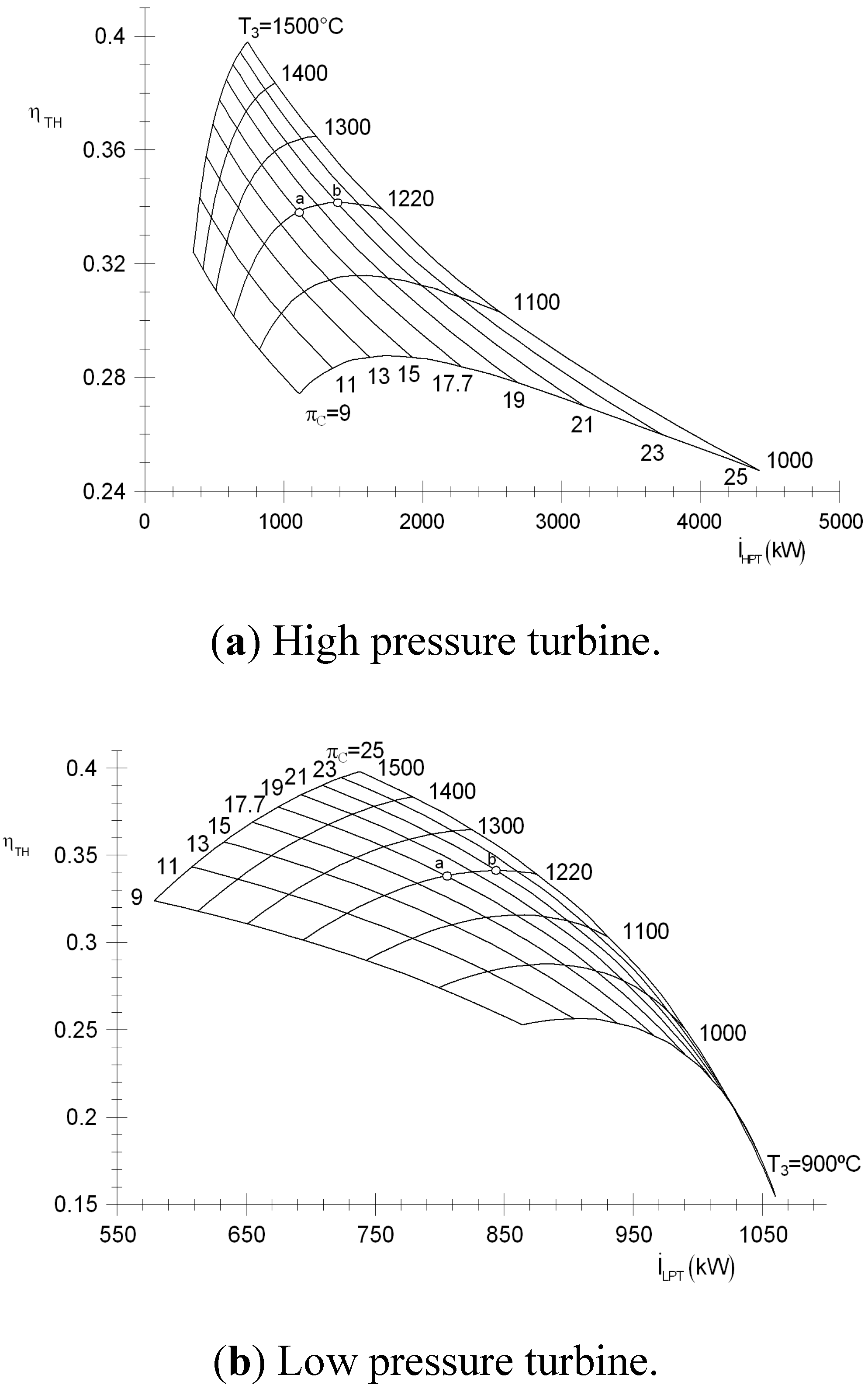
Figure 10a,b show the thermal efficiency variation as a function of the irreversibility rates in low and high pressure turbines, respectively, for different high pressure turbine inlet temperatures and pressure ratios of the compressor. The high pressure turbine generates twice the amount of irreversibility as the low pressure turbine. Note, for instance, for a high pressure turbine inlet temperature of 1220 °C, and a decrease of the compression ratios from 21 (point b) to 17.7 (point a) there is a reduction of the irreversibility in the low pressure turbine of 100 kW and of 500 kW in high pressure turbines.
The values of the irreversibilities agree with the tendencies of the results that present Hakan Aydin [
2]; nevertheless, it disagrees with tendencies of the results of the low pressure turbine, maybe because he analyzes an areoderivate gas turbine with an NGV by increasing the low pressure turbine inlet temperature.
Figure 10.
Thermal efficiency on the irreversibility rate for different high pressure turbine inlet temperatures and pressure ratios of the compressor.
Figure 10.
Thermal efficiency on the irreversibility rate for different high pressure turbine inlet temperatures and pressure ratios of the compressor.
5. Conclusions
A simple methodology has been presented in this paper to estimate the values of the pressure ratio and the high pressure turbine inlet temperature for the operation of an aeroderivate gas turbine. The presented methodology shows that the high pressure turbine inlet temperature is 1220 °C and the pressure ratio is 17.7. The information to estimate the high pressure turbine inlet temperature and pressure ratio was obtained from operation actual values of an aeroderivate gas turbine Mars 100 that is operating on an offshore platform.
With the same methodology, a parametric analysis is pursued and the results presented show that the larger irreverisibilities are generated in the combustion chamber with 36.48% of the total inlet exergy, in the compressor shows 8.21%, the high pressure turbine is 3.05%, and low pressure turbine is 3.55%, respectively. Results show that the exergetic efficiencies are: compression of 91.7%, combustion chamber of 92.6%, low and high pressure turbines of 95% and 93.5%, respectively. The thermal efficiency for the optimal pressure ratio is 1% lower than that by the pressure ratio of 17.7; nevertheless, the irreversibilities decrease approximately 1 GW when a11.86 MW is generated, due to the fact that the irreversibilities are incremented in the process of compression and the expansion of the free turbine. The presented results also show that, if the compression efficiency decreases from 86% to 84%, the irreversibilities of the compressor increase 18.85%; the irreversibilities in the combustion chamber are increased 1.48%; the irreversibilities in the high pressure turbine are increased 6.97% and in the free turbine, 0.14%. In this manner, this paper provides evidence that if the turbine efficiency decreases, the combustion chamber is more affected due to the increase of the fuel flow rate by producing the power required.


 ,
, 


