Article

Determining the Optimum Inner Diameter of Condenser Tubes Based on Thermodynamic Objective Functions and an Economic Analysis

Institute of Heat Engineering, Warsaw University of Technology, 21/25 Nowowiejska Str., 00-665 Warsaw, Poland
*
Author to whom correspondence should be addressed.
Submission received: 1 October 2016 / Revised: 3 December 2016 / Accepted: 6 December 2016 / Published: 10 December 2016
(This article belongs to the Special Issue Entropy in Computational Fluid Dynamics)

Abstract

:
The diameter and configuration of tubes are important design parameters of power condensers. If a proper tube diameter is applied during the design of a power unit, a high energy efficiency of the condenser itself can be achieved and the performance of the whole power generation unit can be improved. If a tube assembly is to be replaced, one should verify whether the chosen condenser tube diameter is correct. Using a diameter that is too large increases the heat transfer area, leading to over-dimensioning and higher costs of building the condenser. On the other hand, if the diameter is too small, water flows faster through the tubes, which results in larger flow resistance and larger pumping power of the cooling-water pump. Both simple and complex methods can be applied to determine the condenser tube diameter. The paper proposes a method of technical and economic optimisation taking into account the performance of a condenser, the low-pressure (LP) part of a turbine, and a cooling-water pump as well as the profit from electric power generation and costs of building the condenser and pumping cooling water. The results obtained by this method were compared with those provided by the following simpler methods: minimization of the entropy generation rate per unit length of a condenser tube (considering entropy generation due to heat transfer and resistance of cooling-water flow), minimization of the total entropy generation rate (considering entropy generation for the system comprising the LP part of the turbine, the condenser, and the cooling-water pump), and maximization of the power unit’s output. The proposed methods were used to verify diameters of tubes in power condensers in a200-MW and a 500-MW power units.

1. Introduction

Condensers are used in steam power plants to close the thermal cycle and transfer the heat of condensation to the environment. Condensers are normally shell-and-tube heat exchangers where steam fed from the low-pressure (LP) part of the turbine condenses. For steam condensation, water is used and it can be drawn from a large water reservoir or a watercourse, such as a river, sea or lake (an open cooling cycle) or from a basin located under a cooling tower (a closed cooling cycle) [1]. Parameters (temperature and the mass flow rate) of cooling water at the condenser inlet affect the pressure of condensing steam, which in turn impacts on the power generated in the LP part of the turbine. The higher the temperature of cooling water at the condenser inlet is, the higher the pressure of the condensing steam becomes [2,3,4,5]. As the cooling-water mass flow rate rises, steam pressure in the condenser decreases [6,7], while the resistance to flow and power supplied to the cooling-water pump increase. Thus, choosing appropriate parameters of the condenser’s operation and geometry (tube diameter, heat transfer area, condenser length, and the number of tube) for a given power unit is an issue involving multiple criteria. The condenser is located under the LP part of the turbine; therefore the condenser length is determined by the length of the LP part. When steam power units are retrofitted, the condenser may be subject to an upgrade; during such an upgrade it is possible to install tubes of a corrected diameter that provides better condenser performance. Choosing condenser tubes of a diameter that is too large (over-dimensioning) increases the heat transfer area and costs of building the condenser. Furthermore, if, for a constant cooling-water mass flow rate, the tube diameter is too large, water flows through the tubes at a lower speed and heat transfer conditions deteriorate, e.g., the heat transfer coefficient on the water side is lower. On the other hand, if the diameter is too small, water flows faster through the tubes, which improves heat transfer conditions, but also results in larger flow resistance and larger pumping power (more electric power is used by the cooling-water pump). When determining the appropriate diameter of condenser tubes, one should consider multiple issues, and this paper focuses on the issue of choosing the right diameter. The tube diameter was examined for a condenser in a 200-MW and a 500-MW power units, since units of this capacity are currently in the process of modernization in Poland. In addition, the units differ in capacity and efficiency, and their condensers have tubes of different inner diameters. To this end, an economic method was applied, taking into account the profit from electric power generation and costs of pumping cooling-water and building the condenser. The results obtained by this method were compared with those provided by the following simpler methods: minimization of the entropy generation rate per unit length of a condenser tube (considering entropy generation due to heat transfer and resistance of cooling-water flow), minimization of the total entropy generation rate (considering entropy generation in the LP part of the turbine and the cooling-water pump), and maximization of the power unit’s output.
Two fundamental physical phenomena occur in heat exchangers: transfer of heat from the hot medium to the cold one, and resistance of the media to flow. These two processes can be compared and their combined effect can be calculated based on entropy generation. According to the second law of thermodynamics, the heat flow and flow resistance, being irreversible processes, are accompanied by entropy generation. The entropy generation represents irreversible processes, involving losses, which is why designers of heat exchangers should bear in mind that the irreversible processes should be kept as minimum as possible. In a per-unit model of the entropy generation rate for a condenser, the entropy generation resulting from the heat flow and the resistance to flow on the cooling-water side per unit length of a condenser tube are taken into account [8,9,10]. The cooling-water mass flow rate affects the condenser performance and parameters, and the power required by the cooling-water pump. A change in steam pressure in the condenser is followed by a change in the power of the LP part of the turbine. Hence, in addition to entropy generation in the condenser due to heat flow and cooling-water flow resistance, the model of the total entropy generation rate also considers entropy generation in the LP part of the turbine and in the cooling-water pump. Since the main purpose of a steam power unit is generating electric power, the model involving the unit’s maximum output serves to examine the difference between the power generated by the turbine and the power required to drive the cooling-water pump. Assuming a constant rate of heat flow provided in fuel fed to a boiler, the maximum output of the power unit matches the output at the unit’s maximum efficiency. Papers analysing the efficiency and output of power units include [11,12,13,14,15]. The economic approach to choosing the shell-and-tube heat exchanger geometry commonly uses a cost-based method taking into account costs of building the heat exchanger and forcing out media with pumps on an annual basis [16,17,18,19,20,21]. Algorithms used to determine optimum heat exchanger geometry with the cost-based objective function include genetic algorithms and particle swarm algorithms [22,23,24,25], the Artificial Bee Colony (ABC) algorithm [26], the imperialist competitive algorithm (ICA) [27], the biogeography-based (BBO) algorithm [28], the gravitational search algorithm [29], and the electromagnetism-like algorithm (EM) [30]. Optimization functions involving the total cost of condenser construction and exergy losses can also be found in the literature [31,32,33]. The parameters of a condenser in a steam power unit affect the power generated by the LP part of the turbine. Therefore, in this paper, to analyze the choice of the optimum inner diameter of condenser tubes from the economic point of view, a formula was used taking into account the profit from electric power generation by the LP part of the turbine less the cost of pumping cooling water and of building the condenser on a one-year basis. The method of the minimum entropy rate generation was used as complementary to the economic method, since the former reflects the contribution of design parameters of equipment, including the steam condenser, to losses occurring during operation of the equipment. To determine the optimum condenser tube diameter, in addition to the appropriate objective function, one should also consider constraints, such as minimum and maximum flow velocities of water in the tubes, maximum pressure drop and geometrical constraints [34,35,36,37]. The issue of choosing the right inner diameter relates not only to heat exchangers but also to district heating pipelines [38,39,40,41].
Mathematical modelling and heat transfer numerical simulations of power condensers have been carried out for many years by a number of scientists. Zero-dimensional [42,43,44,45,46,47,48,49,50], one-dimensional [49], two-dimensional [50,51,52,53,54,55,56,57], quasi-three-dimensional [58,59,60,61], and even three-dimensional [62,63] models have been developed. Due to considerable dimensions of power condensers (as the largest shell-and-tube heat exchangers), two-dimensional models are most often used from among multi-dimensional ones. In the paper, a zero-dimensional model of the condenser (an initial analysis) was chosen to determine the optimal condenser tube diameter. If, in the process of retrofitting the units considered, further analysis of this issue is required, tube diameters are planned to be verified using a two-dimensional model of the condenser.

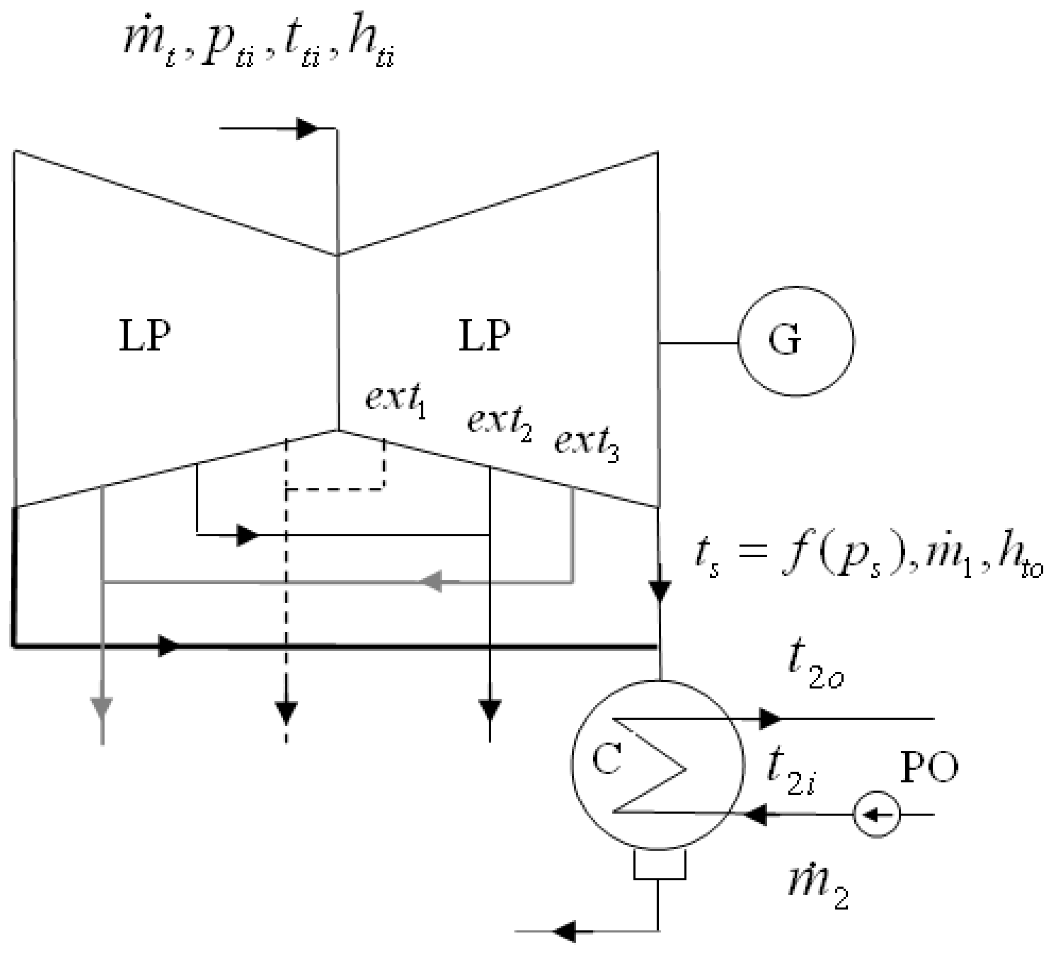
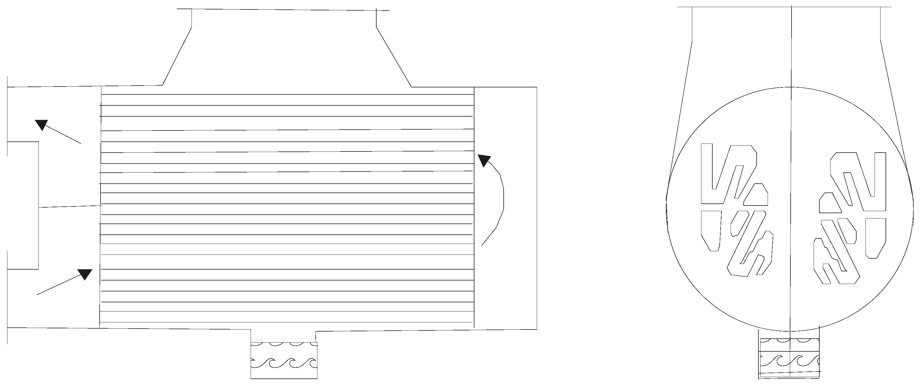
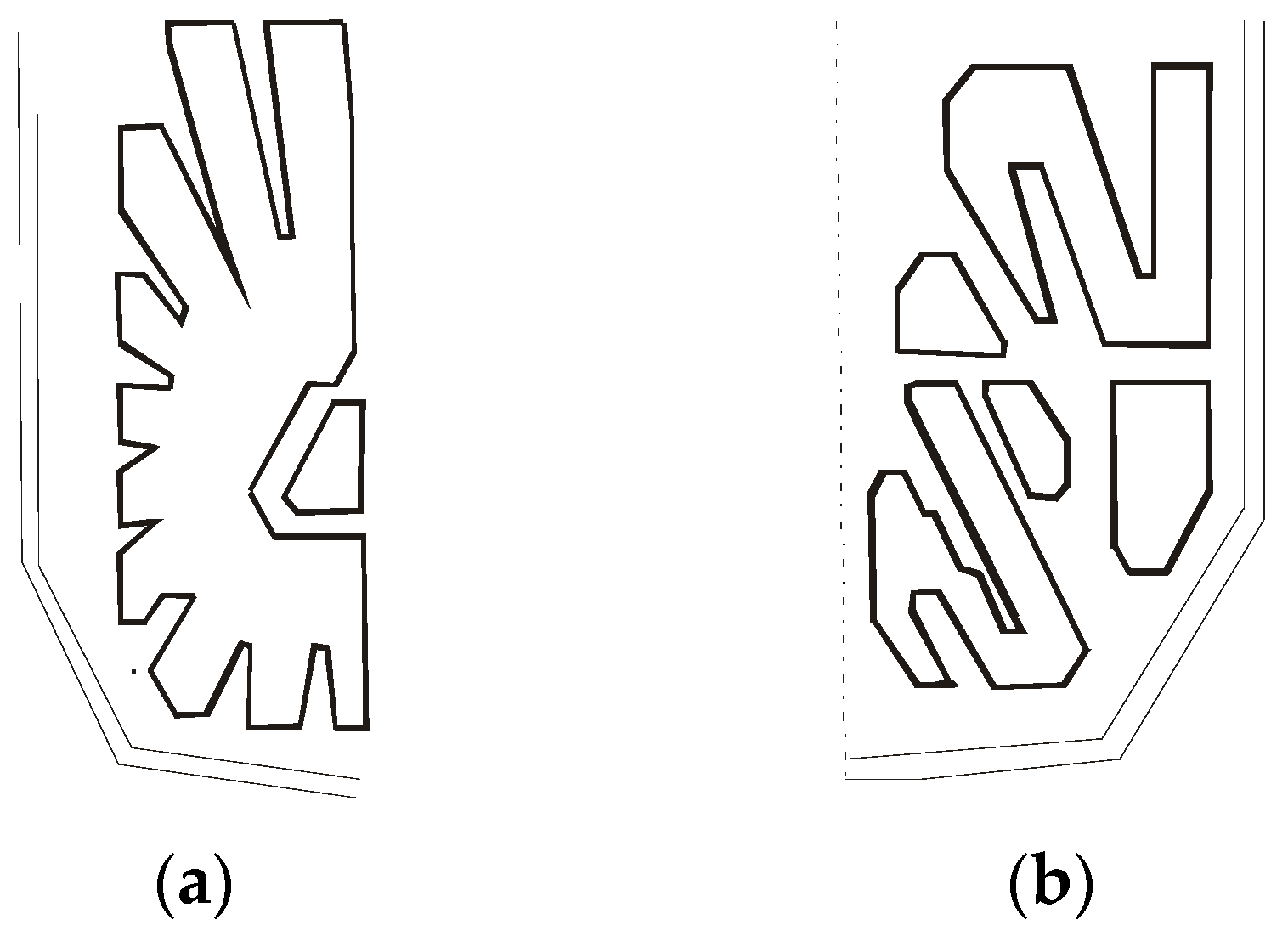
2. Description of Condensers under Consideration

Figure 1 shows the part of the thermal system including the subsystem considered of the 500-MW power unit: the LP part of the turbine, the condenser, and the cooling-water pump, with the notation used.
The connections between the LP part of the turbine, the condenser, and the cooling-water pump are similar in the case of the 200-MW unit, the difference being that the LP part in the 200-MW unit has only one extraction (ext1).
A diagram of a typical two-pass condenser in a steam power unit is shown in Figure 2. The condensers of the two power units are also two-pass designs, but their tube bundles are significantly different (Figure 3).
Basic specifications of condensers in the 200-MW and the 500-MW power units are listed in Table 1 and Table 2, respectively.

3. Mathematical Models for Determining the Optimum Condenser Tube Diameter

To find the correct condenser tube diameter, one should consider quantities reflecting heat transfer and hydraulic resistance. The flow rate of heat in a condenser is described by the Péclet equation [44,45]:
Q ˙ = U A Δ t ln
The logarithmic mean temperature difference has the form:
Δ t ln = ( t s t 2 o ) ( t s t 2 i ) ln ( t s t 2 o t s t 2 i )
The overall heat transfer coefficient (U) was taken as for a cylindrical wall according to the equation:
U = 1 d 2 o α 2 d 2 i + d 2 o 2 λ m ln ( d 2 o d 2 i ) + δ f λ f + 1 α 1
The coefficient of heat transfer ( α 2 ) from cooling water to tube walls was determined from the Dittus–Boelter equation [44,45]:
α 2 = 0.023 Re 2 0.8 Pr 2 0.4 ( λ 2 d 2 i )
The equation for heat transfer on the side of condensing steam α 1 was evaluated from the equation proposed by Szkłowier [47,48]:
α 1 = C m Π s 0.1 N u n 0.5 ( 1 + z 2 ) 0.33 s f .0.15 ε o 0.04 α p
The Nusselt number ( N u n ), the heat transfer coefficient for steam condensation ( α p ) on a single clean horizontal tube, and the geometric parameter of steam inflow per bank ( s f ) are determined from the following equations, respectively:
N u n = α p d 2 o λ 1
α p = 0 . 728 ( ρ k λ k 3 r g ν k Δ t p d 2 o ) 0.25
s f = f A = S L π d 2 o n L
Szkłowier determined the similarity number Π s for a bank of tubes in a condenser as:
Π s = w 1 2 ρ 1 ρ k d 2 o g
The velocity of steam at the bank inlet, essential for heat transfer conditions in the steam condenser, can be determined from the equation:
w 1 = m ˙ 1 ρ 1 f = m ˙ 1 ρ 1 s f A
The heat transfer area is:
A = π d 2 o L n
On considering Equations (3) and (4), the heat flow rate can be given including thermal resistance per unit length as:
Q ˙ = 1 r l L n Δ t ln
The thermal resistance per unit length is:
r l = 1 π ( 1 α 2 d 2 i + 1 2 λ m ln ( d 2 o d 2 i ) + 1 α 1 d 2 o )
The minimum of the thermal resistance per unit length is where heat transfer conditions are the most favourable. To determine the condenser tube diameter, one should also take the resistance to flow into account. Hydraulic losses due to water flow through condenser tubes were obtained from the equation:
Δ p = λ f r ρ 2 w 2 2 2 L d 2 i
where the flow resistance coefficient is a function of the Reynolds number and roughness according to the equation:
λ f r = 0.25 [ log ( k 3.7 d 2 i + 5.74 Re 2 0.9 ) ] 2
The simultaneous effect of heat transfer and flow resistance can be considered according to the second law of thermodynamics, since these phenomena are accompanied by entropy generation resulting from irreversible processes.

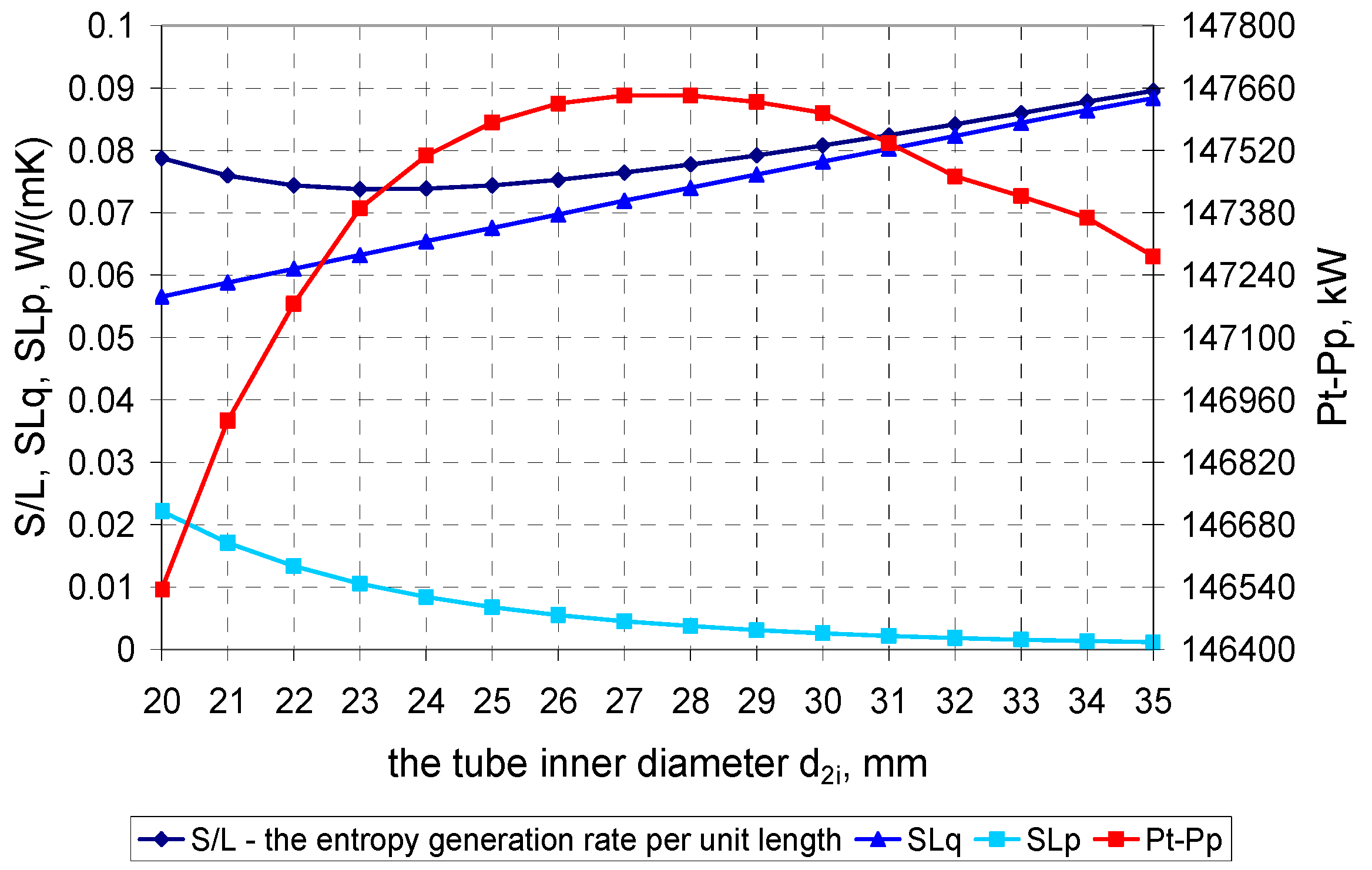
3.1. Minimization of the Entropy Generation Rate per Unit Length of a Condenser Tube: SL = f(d2i) → min

Entropy generation in the condenser results from heat flow and resistance to flow. The entropy generation rate per unit length of a condenser tube, including the entropy generation due to heat flow ( S ˙ L q ) and flow resistance of cooling water ( S ˙ L p ) can be expressed as [8,9,10]:
S L = q ˙ 2 π λ 2 T 2 2 N u 2 + 8 m ˙ 3 π 2 ρ 2 2 T 2 λ f r d 2 i 5 = S ˙ L q + S ˙ L p
The optimum inner diameter of condenser tubes is obtained by minimization of the entropy generation rate per unit length (Equation (16)).Entropy generation resulting from heat flow and resistance to flow is specified in the proposed equation per unit length of a condenser tube. In the above equation, entropy generation on the condensing steam side is not taken into consideration. In order to include entropy generation on the condensing steam side, entropy balance for the whole condenser is required, which is described by equations in Section 3.2.

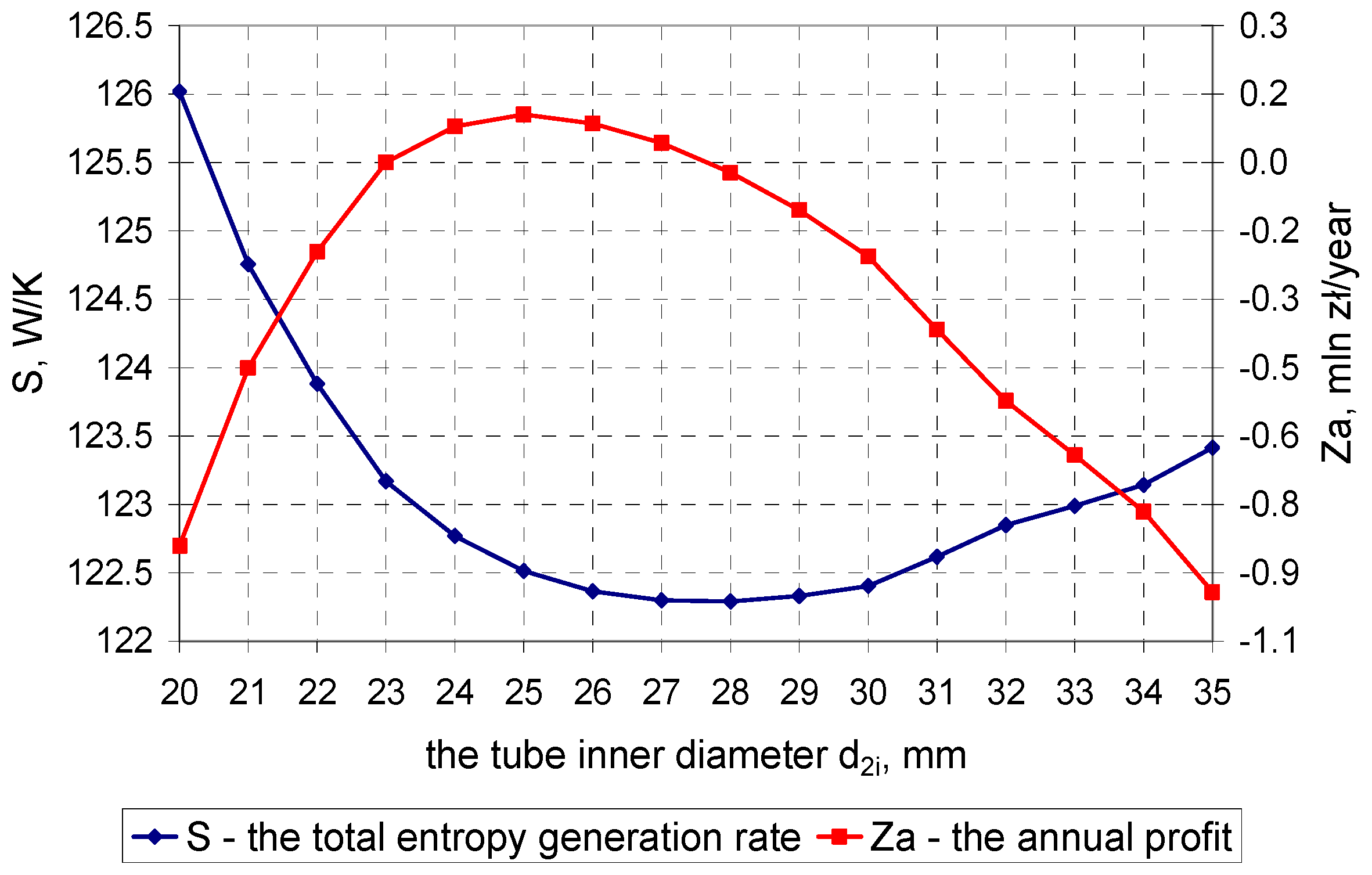
3.2. Minimization of the Total Entropy Generation Rate: S ˙ = f(d2i) → min

A change in the inner diameter of condenser tubes affects the performance of the condenser itself, the LP part of the turbine, and the cooling-water pump. Hence, it is reasonable to analyze the subsystem comprising these components. For the subsystem under consideration (the LP part of the turbine, the condenser, and the cooling-water pump), the model of minimization of the entropy generation rate takes into account five entropy generation components: due to heat flow from condensing steam, heat flow to cooling water, and the resistance of cooling water flow through the condenser tubes, in the cooling-water pump, and in the LP part of the turbine.
The entropy generation rate due to heat transfer on the steam side is:
S ˙ 1 = Q ˙ T s
The entropy generation rate due to heat transfer to cooling water is:
S ˙ 2 , Q ˙ = m ˙ 2 c 2 ln T 2 o T 2 i
The entropy generation rate due to the resistance of cooling water to flow through condenser tubes [7] is:
S ˙ 2 , p = λ f r m ˙ 2 3 2 T 2 ρ 2 2 F 2 2 L d 2 i
The entropy generation rate for the pump equals:
S ˙ p = m ˙ 2 ( s p o s p i )
The entropy generation rate for the LP part of the 500-MW turbine can be given as (Figure 1):
S ˙ t = m ˙ t ( s e x t 1 s t i ) + ( m ˙ t m ˙ e x t 1 ) ( s e x t 2 s e x t 1 ) + ( m ˙ t m ˙ e x t 1 m ˙ e x t 2 ) ( s e x t 3 s e x t 2 ) + m ˙ 1 ( s t o s e x t 3 )
The entropy generation rate for the LP part of the 200-MW turbine can be written as:
S ˙ t = m ˙ t ( s e x t 1 s t i ) + m ˙ 1 ( s t o s e x t 1 )
The total entropy generation rate for the system under consideration is the sum of the five components:
S ˙ = S ˙ 1 + S ˙ 2 , Q ˙ + S ˙ 2 , p + S ˙ p + S ˙ t
The optimum inner diameter of condenser tubes is obtained by minimization of the total entropy generation rate (23). The smallest increase in entropy due to irreversible processes matches the largest power output of the system.

3.3. Maximization of the Power Unit’s Output: P = f(p1(d2i)) → max

A change in the inner diameter of condenser tubes affects the power generated by the LP part of the turbine and the power supplied to the cooling-water pump.
The power generated by the LP part of the 500-MW turbine is (Figure 1):
P t = m ˙ t ( h t i h e x t 1 ) + ( m ˙ t m ˙ e x t 1 ) ( h e x t 1 h e x t 2 ) + ( m ˙ t m ˙ e x t 1 m ˙ e x t 2 ) ( h e x t 2 h e x t 3 ) + m ˙ 1 ( h e x t 3 h t o )
The power generated by the LP part of the 200-MW turbine is:
P t = m ˙ t ( h t i h e x t 1 ) + m ˙ 1 ( h e x t 1 h t o )
The power supplied to the cooling-water pump equals:
P p = m ˙ 2 Δ p p ρ 2 η p = m ˙ 2 ( h p o h p i )
The optimum inner diameter of condenser tubes is obtained by maximization of the power generated by the LP part of the turbine less the power used to drive the cooling-water pump:
P = P t P p
With this criterion the highest power output of the unit can be determined. In order to consider the income from electricity generation and costs of cooling-water pumping and condenser construction, an economic criterion was used; see Section 3.4.

3.4. The Economic Method—Profit Maximization: Z = f(d2i) → max

The economic analysis was based on the unit’s ratings prior to the upgrade of its thermal system, including the condenser.
A surplus profit/loss over N years of planned power plant lifetime was defined as the income from selling surplus electricity less the cost of building the condenser:
Z N = t = 1 N [ ( P t P p ) ( P t r P p r ) ] c e τ a t c A ( A A r )
If, for the sake of simplicity, a constant annual electricity generation (the same in each year of operation) is assumed, Equation (28) can be transformed into:
Z N = [ ( P t P p ) ( P t r P p r ) ] c e τ t = 1 N a t c A ( A A r )
Equation (29) can be rewritten with regard to annual effects Za:
Z a = [ ( P t P p ) ( P t r P p r ) ] c e τ 1 t = 1 N a t c A ( A A r )
where fixed cost ratio is equal to:
f c = 1 t = 1 N a t = d ( 1 + d ) N ( 1 + d ) N 1
Finally, the economic criterion for choosing the condenser tube diameter can be written as follows:
Z a = [ ( P t P p ) ( P t r P p r ) ] c e τ f c c A ( A A r )
The optimum inner diameter of condenser tubes is obtained by maximization of profit according to Equation (32). A change in the condenser tube diameter affects power of the turbine and the cooling-water pump, as well as heat transfer surface in the condenser. Equation (32) considers changes both in the net income from electricity sales and the cost of constructing the condenser.

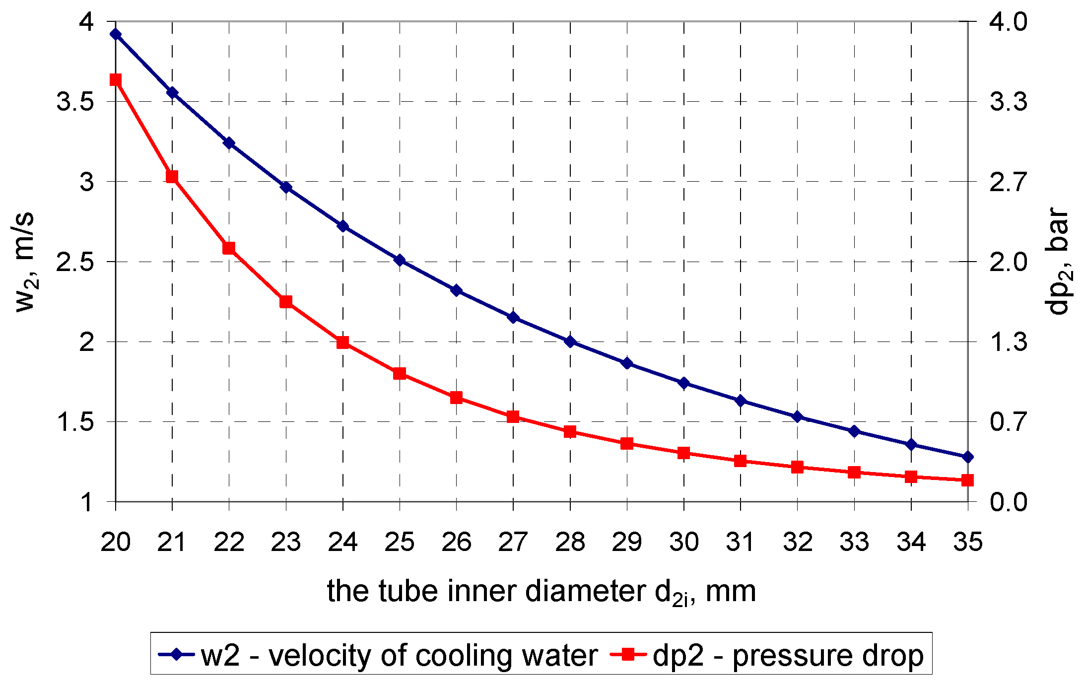
4. Calculation Results

Condenser parameters, including steam condensation pressure, were calculated using a condenser simulator for steady states. The mathematical model of the condenser used balance and heat flow equations. For the given condenser geometry, the simulator's input variables were: temperature ( t 2 i ), pressure ( p 2 i ), and the mass flow rate of cooling water at the condenser inlet, and the mass flow rate of condensing steam ( m ˙ 1 ); the output variables were: cooling-water temperature at the condenser outlet ( t 2 o ), and pressure of steam condensing in the condenser ( p s ). A detailed description of the condenser model can be found in [7,47,48].The model takes into account the effects of inert gases and deposits and the fact that a change in the inner diameter of condenser tubes is followed by a change in their thickness. Calculations were performed for a constant heat flow rate equal to the heat flow rate at rated operating conditions. The rated heat flow rate for the condenser of the 200-MW (500-MW) unit is Q ˙ = 293 MW ( Q ˙ = 453 MW , respectively). The number of tubes (n) and their length (L) are constant and equal to design data (Table 1 and Table 2). The heat transfer area is given by Equation (11). A constant length of the condenser was assumed, since it is defined by the length of the LP part of the turbine. A constant number of condenser tubes was taken, since for slight alteration of the condenser tube diameter tube sheets can be used. If the alteration of the diameter is considerable, the tube sheets should be replaced.
To evaluate the power output of the LP part of the turbine in the 200-MW unit, the following parameters at the inlet of the LP part of the turbine were used: steam pressure p t i = 0.124 MPa , steam temperature t t i = 178   o C , and steam enthalpy h t i = 2831 kJ / kg . Steam parameters at the extraction (ext1) are the following: pressure p e x t 1 = 0.0299 MPa , temperature t e x t 1 = 69   o C , enthalpy h e x t 1 = 2615.7 kJ / kg , and the steam mass flow rate from the extraction m ˙ e x t 1 = 6.795 kg / s . The efficiency of the group of stages between the inlet of the LP part and the extraction was 0.86.
For the LP part of the turbine in the 500-MW unit, the following parameters at the turbine inlet were taken: steam pressure p t i = 0.554 MPa , steam temperature t t i =   266 o C , and steam enthalpy at the inlet h t i = 2994 kJ / kg . Steam parameters at the first extraction were the following: pressure p e x t 1 = 0.2283 MPa , temperature t e x t 1 = 177   o C , enthalpy h e x t 1 = 2824 kJ / kg , and the steam mass flow rate from the extraction m ˙ e x t 1 = 16.156 kg / s . Steam parameters at the second extraction were the following: pressure p e x t 2 = 0.0717 MPa , temperature t e x t 2 = 90   o C , enthalpy h e x t 2 = 2635 kJ / kg , and the steam mass flow rate from the extraction m ˙ e x t 2 = 9.368 kg / s . Steam parameters at the third extraction were the following: pressure p e x t 3 = 0.0275 MPa , temperature t e x t 3 = 67   o C , enthalpy h e x t 3 = 2525 kJ / kg , and the steam mass flow rate from the extraction m ˙ e x t 3 = 12.1 kg / s . The efficiency of the group of stages between the inlet of the LP part and the first extraction was 0.867, between the first and second extractions 0.90, and between the second and third extractions 0.735.
For both the turbines, a constant efficiency of the group of stages between the last extraction and the outlet of the LP part of the turbine, equal to 0.8, was used. A change in the power of the LP part of the turbine resulted from a change in steam pressure in the condenser; the steam pressure in the condenser changes if the condenser tube diameter, and therefore the heat transfer area, is modified. Since pressure in the condenser varied relatively slightly, the parameters at the inlet of the LP part of the turbine and at the extractions were assumed to be constant. A constant efficiency of the cooling-water pump, equal to η p = 0.72 , was taken [42] for a 200-MW unit’s pump; for a cooling-water pump of a 500-MW unit, a constant efficiency was taken, equal to η p = 0.86 .
The following values were used in the economic analysis: the electricity price c e = 180 z ł / MWh (1zł = 4.4 euro), the annual power plant operation time τ = 7000 h , the price of one square metre of the heat transfer area c A = 700 z ł / m 2 , and the fixed cost ratio f c = 0.12 .

4.1. Calculation Results for the Condenser in the 200-MW Power Unit

Based on data obtained from the condenser model, Figure 4 shows velocity of cooling water in tubes and pressure drop on the cooling-water side.
For a constant cooling-water mass flow rate, the larger the condenser tube diameter, the lower velocity in tubes, which follows from the continuity equation. For a lower velocity of cooling water in tubes, pressure drop on the cooling-water side is smaller—Equation (14). If velocity of water in condenser tubes is lower, the heat transfer coefficient on the water and steam sides is smaller, and, consequently, the overall heat transfer coefficient becomes smaller (Figure 5). With a constant heat flow rate, decreasing the overall heat transfer coefficient despite the increase in the heat transfer area results in deterioration of heat transfer conditions, and, as a consequence, to a drop in the UA product (Figure 6). Hence, the rise in condensing steam pressure occurs, which can be seen in Figure 5. The drop in condensing steam pressure with increasing heat transfer area, which was reported in [64,65], relates to a constant tube diameter and variable length or number of tubes. In the case considered in the paper, the number and length of tubes are constant, while the tube inner diameter varies, which is why a slight pressure increase can be observed.
Following the decrease in the product of the overall heat transfer coefficient and the heat transfer area, the thermal resistance per unit length (13) rises (Figure 6).
The effect of the tube inner diameter on power generated by the LP part of the turbine (25) and on power required to drive the cooling-water pump (26) is shown in Figure 7.
An increase in the tube inner diameter is followed by a slight increase in steam pressure, which results in the drop in power of the LP part of the turbine, since steam expands to a higher pressure. The lower pumping power is a consequence of a lower velocity of cooling water in condenser tubes due to their larger inner diameter.
The power unit’s net output, i.e., the difference between the power generated by the LP part of the turbine and that used by the cooling-water pump, and the entropy generation rate per unit length of a condenser tube (16 with its two components are plotted in Figure 8).
The minimum entropy generation rate per unit length of a condenser tube according to Equation (16) was obtained for the tube inner diameter of 27 mm. The larger the condenser tube diameter, the lower the speed of cooling-water in tubes, which results in a drop in entropy generation per unit length of a condenser tube due to resistance to flow. As the speed of cooling-water in tubes becomes lower, the Nusselt number on the water side is smaller, and entropy generation increases due to heat flow per unit length of a condenser tube according to Equation (16). The maximum difference between the power generated by the LP part of the turbine and that required to drive the cooling-water pump (27) was obtained for the tube inner diameter of 31 mm.
Figure 9 displays the total entropy generation rate for the system under consideration (23), comprising the LP part of the turbine, the condenser, and the cooling-water pump, and the annual surplusprofit according to Equation (32).
The minimum total entropy generation rate for the system under consideration occurs for the diameter of 31 mm, i.e., the one for which the maximum power is generated (Figure 8). The highest annual surplus profit, being the essential criterion for choosing the condenser tube diameter, was achieved at the diameter of 29 mm. For condenser tube diameters between 27 mm and 33 mm, the graph of the annual surplus profit is rather flat but has a maximum. In this case, a possibly small change in the diameter is recommended, for the condenser in question to a diameter of 29 or 30 mm.

4.2. Calculation Results for the Condenser in the 500-MW Power Unit

Similarly to the 200-MW unit condenser above, Figure 10, Figure 11, Figure 12 and Figure 13 depict changes in heat flow parameters of the condenser in the 500-MW unit. Figure 10 shows velocity of cooling water in tubes and pressure drop on the cooling-water side. Figure 11 displays the overall heat transfer coefficient and steam pressure in the condenser as functions of the tube inner diameter. The thermal resistance per unit length (13) and the product of the overall heat transfer coefficient and the heat transfer area as functions of the tube inner diameter are plotted in Figure 12. The effect of the tube inner diameter on power generated by the LP part of the turbine (24) and on power required to drive the cooling-water pump (26) is shown in Figure 13.
The entropy generation rate per unit length of a condenser tube according to Equation (16) with its two components and the difference between power generated by the LP part of the turbine and power required to drive the cooling-water pump (27) are shown in Figure 14.
The minimum entropy generation rate per unit length of a condenser tube according to Equation (16) was obtained for the tube inner diameter of 24 mm. The maximum difference between the power generated by the LP part of the turbine and that required to drive the cooling-water pump (27) was obtained for the tube inner diameter of 28 mm.
Figure 15 displays the total entropy generation rate for the system under consideration, comprising the LP part of the turbine, the condenser, and the cooling-water pump, and the annual surplus profit according to Equation (32).
The minimum total entropy generation rate for the system under consideration occurs for the diameter of 28 mm, i.e., the one for which the maximum power is generated (Figure 14). The highest annual surplus profit was achieved at the diameter of 25 mm.

5. Conclusions

The paper presents a methodology for choosing the diameter of tubes in a power condenser, involving thermodynamic methods and an economic one. This issue is relevant to both the design of new condensers and the replacement of used tube assemblies in upgraded condensers. Four methods were presented: minimization of the entropy generation rate per unit length of a condenser tube (considering entropy generation due to heat transfer and resistance of cooling-water flow); minimization of the total entropy generation rate for the system comprising the LP part of the turbine, the condenser, and the cooling-water pump; maximization of the power unit’s output; and the economic method (where the criterion of selection is the annual profit calculated as the income from electric power generation less the costs of pumping cooling water and building the condenser).
The methodology was applied to assess the appropriateness of tube diameters for a condenser in a 200-MW and a 500-MW power units. The choice of the diameter was made for equal number of tubes and their lengths (per unit length).
For the 200-MW unit condenser, the minimum entropy generation rate per unit length of a condenser tube according to Equation (16) was obtained for the tube inner diameter of 27 mm. The maximum net power output of the unit was obtained for the tube inner diameter of 31 mm. The minimum total entropy generation rate for the system comprising the LP part of the turbine, the condenser, and the pump occurred for the same diameter. The optimum inner diameter corresponding to the maximum annual profit (Za) is 29 mm. With most condensers of 200-MW power units, the tube inner diameter is 28 mm, while the outer one is 30 mm. For condenser tube diameters between 27 mm and 33 mm, the graph of the annual surplus profit is rather flat, but has a maximum. In this case, a possibly small change in the diameter is recommended, for the condenser in question to a diameter of 29 or 30 mm.
For the 500-MW unit condenser, the minimum entropy generation rate per unit length of a condenser tube according to Equation (16) was obtained for the tube inner diameter of 24 mm.
The tube inner diameter for which the minimum total entropy generation rate for the system comprising the LP part of the turbine, the condenser, and the pump was achieved matches the one for which the maximum power generation was obtained, and equals 28 mm. The highest annual profit was achieved at the optimum inner diameter of 25 mm. With most condensers of a 500-MW power unit, the tube inner diameter is 22.6 mm, while the outer one 24 mm.
The methods of entropy generation minimization (considering both heat transfer and flow resistance) and the method of the unit’s power output maximization are approximate methods for determining the optimum condenser tube diameter. The results shown indicate that the diameter for which the minimum total entropy generation occurs matches the one for which the maximum power is achieved. The diameter obtained with both these methods is slightly larger than the one calculated with the economic (profit-based) method which comprehensively takes into account the power generated by the LP part of the turbine, the power required to drive the pump, the cost of building the condenser, and, indirectly, the entropy generation in the system under consideration.
In this paper, the optimum diameter of condenser tubes was found for constant number and length of the tubes. However, this is not the only approach that can be taken; a constant heat transfer area or a constant pressure in the condenser can also be assumed (while changing the number of condenser tubes accordingly).

Author Contributions

Rafał Laskowski, Adam Smyk, Artur Rusowicz and Andrzej Grzebielec performed the calculations analyzed the data and wrote the paper. All authors have read and approved the final manuscript.

Conflicts of Interest

The authors declare no conflict of interest.

Nomenclature

Aheat transfer area, m2
a t discount factor, -
c 2 specific heat of water, J/(kg·K)
c e electricity price, zł/MWh
c A price of one square meter of the heat transfer area, zł/m2
C m coefficient of heat transfer intensity for steam and water mixture in a bank of tubes
ddiscount rate, -
d 2 i tube inner diameter, m
d 2 o tube outer diameter, m
fsurface area of steam flow across the section between tubes of a bank in the condenser within its outer circumference, m2
f c fixed cost ratio, 1/year
F 2 cross-section of the cooling water flow, m2
ggravitational acceleration, m/s2
hspecific enthalpy, J/kg
kroughness, mm
L tube length, m
n number of tubes, -
Nyears of power plant operation, year
NuNusselt number, -
N u n Nusselt number for steam condensing on a single tube, -
m ˙ rate of mass flow through one tube, kg/s
m ˙ 1 steam mass flow rate to the condenser, kg/s
m ˙ 2 mass flow rate of cooling water, kg/s
m ˙ t steam mass flow rate at the inlet of the low-pressure part of the turbine, kg/s
p pressure, Pa (abs)
Δ p p pressure rise across the pump, Pa
P p pump power, W
P t power generated in the low-pressure part, W
P difference in power between the low-pressure part and the pump, W
PrPrandtl number, -
Q ˙ flow rate of the heat transferred, kW
q ˙ heat flow rate per unit tube length, W/m
r phase transition heat of condensing steam, r = h " ( p s ) h ' ( p s ) , kJ/kg
r l thermal resistance per unit length, mK/W
ReReynolds number, -
sspecific entropy, J/(kg·K)
Scircumference of steam inflow, measured across a section between tubes outside the bank, m
S ˙ sum of entropy rates, W/K
s f ratio of steam inflow in the area between tubes on the outer circumference of a bank, -
SLentropy generation rate per unit length of a condenser tube, W/(mK)
S ˙ 2 , p entropy generation rate due to the resistance of cooling-water flow, W/K
S ˙ 2 , Q ˙ entropy generation rate due to heat transfer to water, W/K
S ˙ 1 entropy generation rate on the steam side, W/K
S ˙ t entropy generation rate in the low-pressure part, W/K
S ˙ p entropy generation rate in the pump, W/K
S ˙ L p entropy generation due to flow resistance of cooling water, W/(mK)
S ˙ L q entropy generation due to heat flow, W/(mK)
T 2 i cooling water temperature at the condenser inlet, K
T 2 o cooling water temperature at the condenser outlet, K
T 2 average cooling water temperature, ( T 2 o + T 2 i ) / 2 , K
T s steam saturation temperature, K
Δ t ln logarithmic temperature difference across the steam condenser, °C
Δ t p mean temperature difference between steam and the external surface of tubes, °C
U overall heat transfer coefficient, kW/(m2·K)
w velocity, m/s
znumber of tube runs in a condenser, -
Z a annual surplusprofit, zł/year
Z n profit over N years of operation, zł
α coefficient of heat transfer, kW/(m2·K)
α p heat transfer coefficient for steam condensation on a single horizontal tube, kW/(m2·K)
δ f thickness of the fouling layer, m
ε o ratio of air content in the condenser to steam flow, -
η p pump efficiency, -
λ 1 thermal conductivity of steam, kW/(mK)
λ 2 thermal conductivity of cooling water, kW/(mK)
λ f thermal conductivity of the fouling layer, kW/(mK)
λ f r flow resistance coefficient, -
λ k thermal conductivity of condensate, kW/(mK)
λ m thermal conductivity of tube material, kW/(mK)
ν k kinematic viscosity of condensate, m2/s
Π s similarity number for a bank of tubes, -
ρ density, kg/m3
ρ k density of condensate, kg/m3
τ annual power plant operation time, h

Subscripts

1relates to steam
2relates to cooling water
extrelates to parameters at the extraction in steam turbine
ffouling
mtube material
tirelates to parameters at the inlet of the low-pressure part
torelates to parameters at the outlet of the low-pressure part
pirelates to parameters upstream the pump
porelates to parameters downstream the pump
rrelates to reference (nominal) parameters

References

  1. Nag, P.K. Power Plant Engineering; Tata McGraw-Hill Education: New York, NY, USA, 2002. [Google Scholar]
  2. Haseli, Y.; Dincer, I.; Naterer, G.F. Optimum temperatures in a shell and tube condenser with respect to exergy. Int. J. Heat Mass Transf. 2008, 51, 2462–2470. [Google Scholar] [CrossRef]
  3. Laskowski, R.; Smyk, A. Analysis of the working conditions of a steam condenser using measurements and an approximation model. Rynek Energii 2014, 1, 110–115. [Google Scholar]
  4. Laskowski, R.; Smyk, A.; Lewandowski, J.; Rusowicz, A. Cooperation of a Steam Condenser with a Low-pressure Part of a Steam Turbine in Off-Design Conditions. Am. J. Energy Res. 2015, 3, 13–18. [Google Scholar]
  5. Atria, S.I. The influence of condenser cooling water temperature on the thermal efficiency of a nuclear power plant. Ann. Nucl. Energy 2015, 80, 371–378. [Google Scholar]
  6. Anozie, A.N.; Odejobi, O.J. The search for optimum condenser cooling water flow rate in a thermal power plant. Appl. Therm. Eng. 2011, 31, 4083–4090. [Google Scholar] [CrossRef]
  7. Laskowski, R.; Smyk, A.; Lewandowski, J.; Rusowicz, A.; Grzebielec, A. Selecting the cooling water mass flow rate for a power plant under variable load with entropy generation rate minimization. Energy 2016, 107, 725–733. [Google Scholar] [CrossRef]
  8. Bejan, A. Entropy generation minimization: The new thermodynamics of finite size devices and finite time processes. J. Appl. Phys. 1996, 79, 1191–1218. [Google Scholar] [CrossRef]
  9. Laskowski, R.; Rusowicz, A.; Smyk, A. Verification of the condenser tubes diameter based on the minimization of entropy generation. Rynek Energii 2015, 1, 71–75. [Google Scholar]
  10. Laskowski, R.; Rusowicz, A.; Grzebielec, A. Estimation of a tube diameter in a ‘church window’ condenser based on entropy generation minimization. Arch. Thermodyn. 2015, 36, 49–59. [Google Scholar]
  11. Erdem, H.H.; Akkaya, A.V.; Cetin, B.; Dagdas, A.; Sevilgen, S.H.; Sahin, B.; Teke, I.; Gungor, C.; Atas, S. Comparative energetic and exergetic performance analyses for coal-fired thermal power plants in Turkey. Int. J. Therm. Sci. 2009, 48, 2179–2186. [Google Scholar] [CrossRef]
  12. Aljundi, I.H. Energy and exergy analysis of a steam power plant in Jordan. Appl. Therm. Eng. 2009, 29, 324–328. [Google Scholar] [CrossRef]
  13. Datta, A.; Sengupta, S.; Duttagupta, S. Exergy analysis of a coal-based 210 MW thermal power plant. Int. J. Energy Res. 2007, 31, 14–28. [Google Scholar]
  14. Wołowicz, M.; Milewski, J.; Badyda, K. Feedwater repowering of 800 MW supercritical steam power plant. J. Power Technol. 2012, 92, 127–134. [Google Scholar]
  15. Milewski, J.; Bujalski, W.; Wołowicz, M.; Futyma, K.; Kucowski, J. Off-design operation of an 900 MW-class power plant with utilization of low temperature heat of flue gases. J. Power Technol. 2015, 95, 221–227. [Google Scholar]
  16. Soltan, B.K.; Saffar-Avval, M.; Damangir, E. Minimizing capital and operating costs of shell and tube condensers using optimum baffle spacing. Appl. Therm. Eng. 2004, 24, 2801–2810. [Google Scholar] [CrossRef]
  17. Fertaka, S.; Thibault, J.; Gupta, Y. Design of shell-and-tube heat exchangers using multiobjective optimization. Int. J. Heat Mass Transf. 2013, 60, 343–354. [Google Scholar] [CrossRef]
  18. Allen, B.; Gosselin, L. Optimal geometry and flow arrangement for minimizing the cost of shell-and-tube condensers. Int. J. Energy Res. 2008, 32, 958–969. [Google Scholar] [CrossRef]
  19. Wildi-Tremblay, P.; Gosselin, L. Minimizing shell-and-tube heat exchanger cost with genetic algorithms and considering maintenance. Int. J. Energy Res. 2007, 31, 867–885. [Google Scholar] [CrossRef]
  20. Caputo, A.C.; Pelagagge, P.M.; Salini, P. Heat exchanger design based on economic optimization. Appl. Therm. Eng. 2008, 28, 1151–1159. [Google Scholar] [CrossRef]
  21. Azad, A.V.; Amidpour, M. Economic optimization of shell and tube heat exchanger based on constructal theory. Energy 2011, 36, 1087–1096. [Google Scholar] [CrossRef]
  22. Hajabdollahi, H.; Ahmadi, P.; Dincer, I. Thermoeconomic optimization of a shell and tube condenser using both genetic algorithm and particle swarm. Int. J. Refrig. 2011, 34, 1066–1076. [Google Scholar] [CrossRef]
  23. Sadeghzadeh, H.; Ehyaei, M.A.; Rosen, M.A. Techno-economic optimization of a shell and tube heat exchanger by genetic and particle swarm algorithms. Energy Convers. Manag. 2015, 93, 84–91. [Google Scholar] [CrossRef]
  24. Selbas, R.; Kızılkan, O.; Reppich, M. A new design approach for shell-and-tube heat exchangers using genetic algorithms from economic point of view. Chem. Eng. Process. 2006, 45, 268–275. [Google Scholar] [CrossRef]
  25. Patel, V.K.; Rao, R.V. Design optimization of shell-and-tube heat exchanger using particle swarm optimization technique. Appl. Therm. Eng. 2010, 30, 1417–1425. [Google Scholar] [CrossRef]
  26. Sahin, A.S.; Kilic, B.; Kilic, U. Design and economic optimization of shell and tube heat exchangers using Artificial Bee Colony (ABC) algorithm. Energy Convers. Manag. 2011, 52, 3356–3362. [Google Scholar] [CrossRef]
  27. Hadidi, A.; Hadidi, M.; Nazari, A. A new design approach for shell-and-tube heat exchangers using imperialist competitive algorithm (ICA) from economic point of view. Energy Convers. Manag. 2013, 67, 66–74. [Google Scholar] [CrossRef]
  28. Hadidi, A.; Nazari, A. Design and economic optimization of shell-and-tube heat exchangers using biogeography-based (BBO) algorithm. Appl. Therm. Eng. 2013, 51, 1263–1272. [Google Scholar] [CrossRef]
  29. Mohanty, D.K. Gravitational search algorithm for economic optimization design of a shell and tube heat exchanger. Appl. Therm. Eng. 2016, 107, 184–193. [Google Scholar] [CrossRef]
  30. Abed, A.M.; Abed, I.A.; Majdi, H.S.; Al-Shamani, A.N.; Sopian, K. A new optimization approach for shell and tube heat exchangers by using electromagnetism-like algorithm (EM). Heat Mass Transf. 2016, 52, 2621–2634. [Google Scholar] [CrossRef]
  31. Ozcelik, Y. Exergetic optimization of shell and tube heat exchangers using agenetic based algorithm. Appl. Therm. Eng. 2007, 27, 1849–1856. [Google Scholar] [CrossRef]
  32. Eryener, D. Thermoeconomic optimization of baffle spacing for shell and tube heat exchangers. Energy Convers. Manag. 2006, 47, 1478–1489. [Google Scholar] [CrossRef]
  33. Can, A.; Buyruk, E.; Eryener, D. Exergoeconomic analysis of condenser type heat exchangers. Exergy Int. J. 2002, 2, 113–118. [Google Scholar] [CrossRef]
  34. Sanaye, S.; Hajabdollahi, H. Multi-objective optimization of shell and tube heat exchangers. Appl. Therm. Eng. 2010, 30, 1937–1945. [Google Scholar] [CrossRef]
  35. Ponce-Ortega, J.M.; Serna-González, M.; Jiménez-Gutiérrez, A. Use of genetic algorithms for the optimal design of shell-and-tube heat exchangers. Appl. Therm. Eng. 2009, 29, 203–209. [Google Scholar] [CrossRef]
  36. Ayala, H.V.H.; Keller, P.; Morais, M.F.; Mariani, V.C.; Coelho, L.S.; Rao, R.V. Design of heat exchangers using a novel multiobjective free search differential evolution paradigm. Appl. Therm. Eng. 2016, 94, 170–177. [Google Scholar] [CrossRef]
  37. Muralikrishna, K.; Shenoy, U.V. Heat exchanger design targets for minimum area and cost. Chem. Eng. Res. Des. 2000, 78, 161–167. [Google Scholar] [CrossRef]
  38. Tol, H.I.; Svendsen, S. Improving the dimensioning of piping networks and network layouts in low-energy district heating systems connected to low energy buildings: A case study in Roskilde, Denmark. Energy 2012, 38, 276–290. [Google Scholar] [CrossRef] [Green Version]
  39. Nussbaumer, T.; Thalmann, S. Influence of system design on heat distribution costs in district heating. Energy 2016, 101, 496–505. [Google Scholar] [CrossRef]
  40. Smyk, A.; Pietrzyk, Z. Dobór średnicy rurociągów w sieci ciepłowniczej z uwzględnieniem optymalnych prędkości wody sieciowej. Rynek Energii 2011, 6, 98–105. (In Polish) [Google Scholar]
  41. Murat, J.; Smyk, A. Dobór średnicy rurociągów w układzie rozgałęźno-pierścieniowym dla przykładowych struktur sieci ciepłowniczej. Rynek Energii 2015, 9, 13–19. (In Polish) [Google Scholar]
  42. Salij, A.; Stępień, J.C. Performance of Turbine Condensers in Power Units of Thermal Systems; Kaprint: Warsaw, Poland, 2013. (In Polish) [Google Scholar]
  43. Rusowicz, A. Issues Concerning Mathematical Modelling of Power Condensers; Warsaw University of Technology: Warsaw, Poland, 2013. (In Polish) [Google Scholar]
  44. Cengel, Y.A. Heat Transfer; McGraw-Hill: New York, NY, USA, 1998. [Google Scholar]
  45. Holman, J.P. Heat Transfer; McGraw-Hill: New York, NY, USA, 2002. [Google Scholar]
  46. Grzebielec, A.; Rusowicz, A. Thermal Resistance of Steam Condensation in Horizontal Tube Bundles. J. Power Technol. 2011, 91, 41–48. [Google Scholar]
  47. Szkłowier, G.G.; Milman, O.O. Issledowanije I Rasczot Kondensacionnych Ustrojstw Parowych Turbin; Energoatomizdat: Moskwa, Russia, 1985. (In Russian) [Google Scholar]
  48. Smyk, A. The Influence of Thermodynamic Parameters of a Heat Cogeneration System of the Nuclear Heat Power Plant on Fuel Saving in Energy System. Ph.D. Thesis, Warsaw University of Technology, Warsaw, Poland, 1999. [Google Scholar]
  49. Chmielniak, T.; Trela, M. Diagnostics of New-Generation Thermal Power Plants; Wydawnictwo IMP PAN: Gdańsk, Poland, 2008. [Google Scholar]
  50. Saari, J.; Kaikko, J.; Vakkilainen, E.; Savolainen, S. Comparison of power plant steam condenser heat transfer models for on-line condition monitoring. Appl. Therm. Eng. 2014, 62, 37–47. [Google Scholar] [CrossRef]
  51. Brodowicz, K.; Czaplicki, A. Condensing Vapour Flow Resistance Throught Tubes Bundle in the Presence of Condensate on Tubes. In Proceedings of the 8th International Heat Transfer Conference, San Francisco, CA, USA, 17–22 August 1986; Volume 4, pp. 1689–1694.
  52. Carlucci, L. Computations of flow and heat transfer in power plant condenser. In Proceedings of the 8th International Heat Transfer Conference, San Francisco, CA, USA, 17–22 August 1986; Volume 5, pp. 2541–2546.
  53. Fujii, T.; Honda, H.; Oda, K. Condensation of Steam on Horizontal Tube—the Influence of Oncoming Velocity and Thermal Conduction at the Tube Wall. In Proceedings of the 18th National Heat Transfer Conference, San Diego, CA, USA, 6–8 August 1979; pp. 35–43.
  54. Fujii, T.; Uehara, H.; Hirata, K.; Oda, K. Heat transfer and flow resistance in condensation of low pressure steam flowing through tube banks. Int. J. Heat Mass Transf. 1972, 15, 247–259. [Google Scholar] [CrossRef]
  55. Malin, M.R. Modelling flow in an experimental marine condenser. Int. Commun. Heat Transf. 1997, 24, 597–608. [Google Scholar] [CrossRef]
  56. Roy, R.P.; Ratisher, M.; Gokhale, V.K. A Computational Model of a Power Plant Steam Condenser. J. Energy Resour. Technol. 2001, 123, 81–91. [Google Scholar] [CrossRef]
  57. Zeng, H.; Meng, J.; Li, Z. Numerical study of a power plant condenser tube arrangement. Appl. Therm. Eng. 2012, 40, 294–303. [Google Scholar] [CrossRef]
  58. Zhang, C. Numerical Modeling Using a Quasi-Three-Dimensional Procedure for Large Power Plant Condenser. J. Heat Transf. 1994, 116, 180–188. [Google Scholar] [CrossRef]
  59. Zhang, C.; Bokil, A. A quasi-three-dimensional approach to simulate the two-phase fluid flow and heat transfer in condensers. Int. J. Heat Mass Transf. 1997, 40, 3537–3546. [Google Scholar] [CrossRef]
  60. Zhang, C.; Sousa, A.C.M.; Venart, J.E.S. Numerical Simulation of Different Types of Steam Surface Condensers, Journal of Energy Resources Technology. Trans. ASME 1991, 113, 63–70. [Google Scholar]
  61. Zhou, L.X.; Li, F.Y.; Li, W.H. Quasi-three-dimensional numerical study of shell side of condenser. Proc. CSEE 2008, 28, 25–30. [Google Scholar]
  62. Nedelkovski, I.; Vilos, I.; Geramitoioski, T. Finite element solution of Navier-Stokes equations for steam flow and heat transfer. Trans. Eng. Comput. Technol. 2005, 5, 171–175. [Google Scholar]
  63. Prieto, M.M.; Suarez, I.M.; Montanes, E. Analisys of the thermal performance of a church window steam condenser for different operational conditions using three models. Appl. Therm. Eng. 2003, 23, 163–178. [Google Scholar] [CrossRef]
  64. Bekdemir, S.; Ozturk, R.; Yumurtac, Z. Condenser Optimization in Steam Power Plant. J. Therm. Sci. 2003, 12, 176–179. [Google Scholar] [CrossRef]
  65. Ozdamar, G.; Ozturk, R. Optimization of a condenser in a thermal power plant. In Proceedings of the 9th International Conference on Heat Transfer, Fluid Mechanics and Thermodynamics, Valletta, Malta, 16–18 July 2012.
Figure 1. The subsystem under consideration, being a part of the 500-MW power unit: the low-pressure part of the turbine (LP) with extractions ext1 to ext3; the condenser (C); and the cooling-water pump (CWP).
Entropy 18 00444 g001
Figure 2. A diagram of a typical two-pass condenser in a steam power unit.
Entropy 18 00444 g002
Figure 3. Tube bundle layout in a condenser of the 500-MW (a) and the 200-MW (b) units.
Entropy 18 00444 g003
Figure 4. Velocity of cooling water in tubes and pressure drop on the cooling-water side in the condenser as functions of the tube inner diameter.
Entropy 18 00444 g004
Figure 5. The overall heat transfer coefficient and steam pressure in the condenser as functions of the tube inner diameter.
Entropy 18 00444 g005
Figure 6. The thermal resistance per unit length and the product of the overall heat transfer coefficient and the heat transfer area as functions of the tube inner diameter.
Entropy 18 00444 g006
Figure 7. Power generated by the LP part of the turbine and power required to drive the cooling-water pump as functions of the tube inner diameter.
Entropy 18 00444 g007
Figure 8. The entropy generation rate per unit length of a condenser tube with its two components, and the difference between the power generated by the LP part of the turbine and that used by the cooling-water pump as functions of the tube inner diameter.
Entropy 18 00444 g008
Figure 9. The total entropy generation rate for the system under consideration, comprising the LP part of the turbine, the condenser, and the cooling-water pump, and the annual surplusprofit as functions of the tube inner diameter.
Entropy 18 00444 g009
Figure 10. Velocity of cooling water in tubes and pressure drop on the cooling-water side in the condenser as functions of the tube inner diameter.
Entropy 18 00444 g010
Figure 11. The overall heat transfer coefficient and steam pressure in the condenser as functions of the tube inner diameter.
Entropy 18 00444 g011
Figure 12. The thermal resistance per unit length and the product of the overall heat transfer coefficient and the heat transfer area as functions of the tube inner diameter.
Entropy 18 00444 g012
Figure 13. Power generated by the LP part of the turbine and power required to drive the cooling-water pump as functions of the tube inner diameter.
Entropy 18 00444 g013
Figure 14. The entropy generation rate per unit length of a condenser tube with its two components and the difference between the power generated by the LP part of the turbine and that used by the cooling-water pump as functions of the tube inner diameter.
Entropy 18 00444 g014
Figure 15. The total entropy generation rate for the system under consideration, comprising the LP part of the turbine, the condenser, and the cooling-water pump, and the annual surplus profit as functions of the tube inner diameter.
Entropy 18 00444 g015
Table 1. Basic specifications of the condenser in the 200-MW power unit [42,43].
ItemSymbolUnitValue
Heat transfer areaAm22 × 5710 = 11,420
Number of tubesn-2 × 6878 = 13,756
Cooling-water mass flow rate m ˙ 2 kg/s2 × 4000 = 8000
Inlet/outlet cooling water temperature, norm.t2i/t2o°C17/25.7
Rated condensed-steam mass flow rate m ˙ 1 kg/s129
Tube outer diameterd2omm30
Tube inner diameterd2imm28
Tube lengthLmm9000
Mean water pressurep2bar (abs)3
Number of passes--2
Table 2. Basic specifications of the condenser in the 500-MW power unit.
ItemSymbolUnitValue
Heat transfer areaAm22 × 9500 = 19,000
Number of tubesn-2 × 16,000 = 32,000
Cooling-water mass flow rate m ˙ 2 kg/s2 × 6700 = 13,400
Inlet/outlet cooling water temperature, norm.t2i/t2ooC24/32
Rated condensed-steam mass flow rate m ˙ 1 kg/s207.5
Tube outer diameterd2omm24
Tube inner diameterd2imm22.6
Tube lengthLmm8000
Mean water pressurep2bar (abs)3
Number of passes--2

