4.1. Effects of Structures
The variations trend of f/f0, Nu/Nu0 and S′/S′0 are similar for different nanofluid concentration cases, so the results of φ = 2% are shown as examples herein to illustrate the effects of structures.
The relative Fanning friction factor
f/f0 (
Figure 2) of microchannel with rectangle and protrusion devices are much larger and smaller than others, respectively, and increase a little as
Re increases. While,
f/f0 of microchannels with cylinder and v-groove devices are medium, and increase quickly with the increase of
Re. To investigate the variation of
f/f0 influenced by the mirochannel structures in detail, the flow structures analysis can be employed. In the studied microchannels,
f/f0 consists of frictional resistance and form drag. The development of flow boundary layer is interrupted due to the presence of flow control devices, and then the frictional resistance decreases. However, the flow separation occurs near the flow control devices, so the form drag increases.
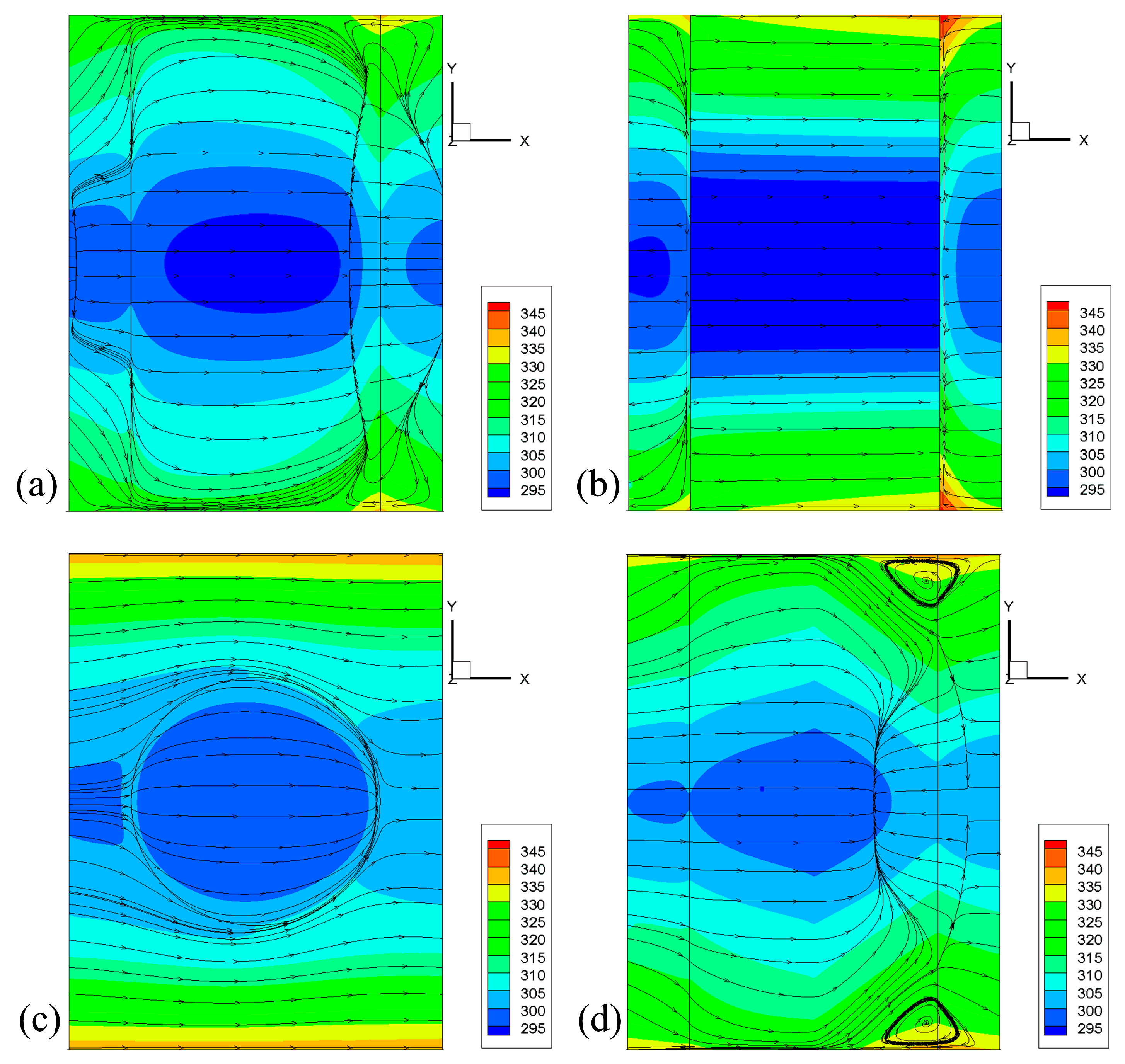
Figure 3 shows the limiting streamlines and temperature contours of the four microchannels in the case of
φ = 2% and
Re = 100. For the microchannel with cylinder (
Figure 3a) devices, flow separates at the tail end of the cylinder, and reattaches in the central upstream of next period domain. The start of flow separation is wide in the channel in the spanwise direction, so the forepart of the separation bubble nearly fills the whole channel. After leaving the cylinder zone, the separation flow reattaches directing the central flow quickly, and finally reattaches near the inlet of the next period domain, forming a large separation bubble, so the whole separation bubble shows a trapezoid-like structure. Then the form drag increases a lot and, therefore, the increase of form drag and
f/f0 of the microchannel with cylinder is maximum. For the microchannel with rectangle (
Figure 3b) devices, part of the main flow impinges directly on the front surface of rectangle and flows backward to the previous period domain from the inlet. While, near the back surface, the cross-section is suddenly enlarged, and then the adverse pressure gradient forms herein, so the backflow from the front of the next period domain flows directly to the back surface of the rectangle, and turns to the main flow, finally, flowing to the outlet together with the main flow. Therefore, the flow domains both ahead and behind the rectangle devices are filled with the separation flow, then the form drag increases sharply. For the microchannel with protrusions (
Figure 3c), the main flow impinges on the front of the protrusion, just leaving curving streamlines on the surface. While the flow separates at the tail end of the protrusion due to the formation of a local advance pressure gradient, and the separation flow reattaches quickly in the wake, so the small separation bubble herein makes the form drag increase slightly. Therefore, the increase of the form drag and
f/f0 of the microchannel with protrusions is a minimum. For the microchannel with v-groove (
Figure 3d) devices, the main flow flows through the front part of the channel with curving streamlines, then separates in the central back of the v-groove devices and reattaches in the wake, so the separation bubble shows a spindle-like structure. Moreover, two small corner vortices form near the walls, due to the combined effects of the non-slip wall and advanced pressure gradient in the channel in the spanwise direction. Furthermore, comparing with that of the microchannel with cylinder devices, the separation bubble locates in the back of channel, not affecting the next period domain. Therefore, the increase of form drag and
f/f0 herein is less than that of the microchannel with cylinder devices. What is more, as the mass flow rate and
Re increase, the separation flow in the microchannels with flow control devices are enhanced, more or less, so their
f/f0 increase gradually.
The variation trend of relative Nusselt number
Nu/Nu0 are more complex than that of
f/f0. As
Figure 4 shows,
Nu/Nu0 of microchannel with cylinder devices are larger than that of others, and, at low
Re cases (
Re = 50 and 100),
Nu/Nu0 of microchannel with protrusion devices are minimum, while, as
Re further increases to 200 and 300,
Nu/Nu0 of microchannel with rectangle are smaller than that of others.
Nu/Nu0 of all microchannels increase with the increase of
Re, except that of microchannel with rectangle devices. Analyzing from temperature contour on the heated surfaces (
Figure 3), heat transfer in the zones before separation, reattachment, and wake, heat transfer is better. It indicates that high heat transfer region is caused by the reattachment and the vortices shedding from the flow control devices, and the low heat transfer region locates in the region of flow separation. In the microchannel with cylinder (
Figure 3a) devices, the large separation bubble fills the back of the channel and the front of the next period domain, especially enhancing the heat and mass transfer between the central flow and the near wall flow in the spanwise direction, and then the average temperature and temperature gradient are the lowest, so its
Nu/Nu0 is larger than others. In the microchannel with rectangle (
Figure 3b) devices, separation flow almost fills both ahead and behind the rectangle, but the heat and mass transfer between the central flow and the near wall flow in the spanwise direction is weakened, then the temperature gradient and average temperature increases, so
Nu/Nu0 is lower. In the microchannel with protrusion (
Figure 3c) devices, the higher temperature and larger temperature gradient are observed, so
Nu/Nu0 is minimum herein. In the microchannel with v-groove (
Figure 3d) devices, although the large separation bubble forms in the back of the channel, showing the enhancement of heat and mass transfer between the central flow and the near wall flow in the spanwise direction, the central low temperature region is small, so the average temperature is medium. Furthermore, as the mass flow rate and
Re increase, the separation flow in the microchannels with cylinder, protrusion, and v-groove devices are enhanced, more or less, so their
Nu/Nu0 increase gradually. Especially, for the microchannel with rectangle devices, starting from the minimum
Re case (
Re = 50), the large-scale separation flow forms and locates ahead and behind of the rectangle, when
Re increases, the separation flow fills the whole of these regions, so the main flow no longer impinges directly on the front surface of the rectangle, and the direct contact area between the main flow and the heated surfaces decreases; therefore, the heat transfer is reduced. Meanwhile, when
Re increases, the heat transfer coefficient of heated surfaces increases, and the local heat transfer is enhanced. Therefore, for the microchannel with rectangle devices, there must be a transition point of
Re for obtaining the largest heat transfer. In the above studied cases, the transition point is
Re = 100. Finally, it can be concluded that not only the scale and intensity of the separation flow, but also the development of the separation bubble in the spanwise direction, can give rise to the
Nu/Nu0.
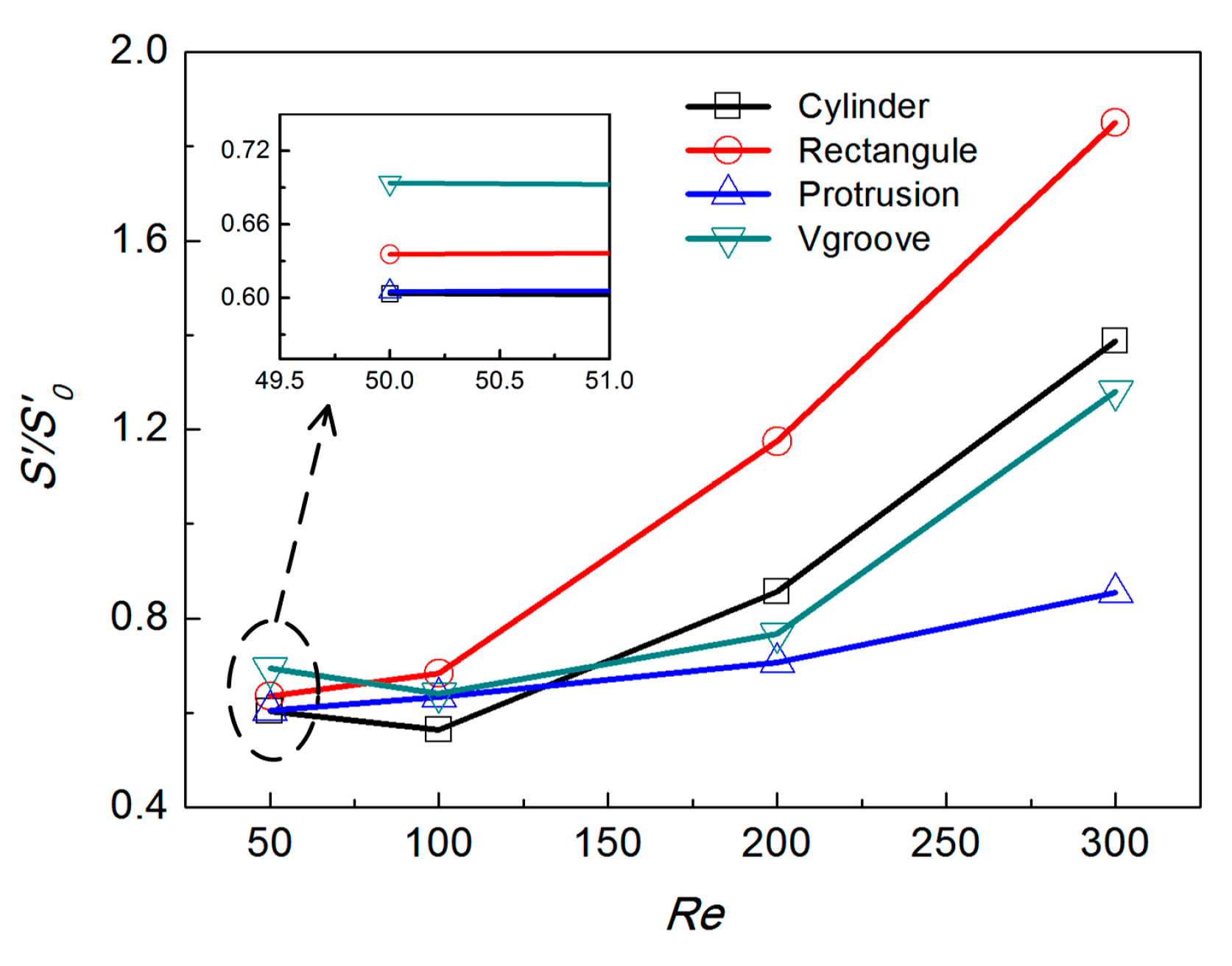
Based on the entropy generation theory and Equation (20), for the given working condition, the entropy generation of microchannel increases with the increase of pressure drop (reflected by Fanning friction factor) and the decrease of heat transfer (reflected by the Nusselt number). Furthermore, due to the nonlinear effect of mass flow rate, the influences of Fanning friction factor on the entropy generation for varied
Re cases are obviously different from that of the Nusselt number. Similar with the above analysis, the relative entropy generation
S′/S′0 of
φ = 2% due to the heat transfer irreversibility and the fluid frictional irreversibility is calculated and shown in
Figure 5. The results reveal that the microchannel with protrusion devices shows favorable entropy generation performance. For the microchannel with rectangle, the large
f/f0 and relative small
Nu/Nu0 make its relative large
S′/S′0, especially at larger
Re cases, so this structure is not suitable for the studied working conditions. The
Nu/Nu0 of microchannels with cylinder and v-groove devices are large enough, but the
f/f0 are also large, so the
S′/S′0 are larger than that of microchannels with protrusion devices in most cases. The results shows that
S′/S′0 are more influenced by
f/f0 at the larger
Re cases, while, more influenced by
Nu/Nu0 at the smaller
Re cases. What is more, the microchannels with cylinder and v-groove devices have better heat flux transfer performance, while the microchannel with protrusion devices is better from the perspective of entropy generation minimization.
4.2. Effects of Nanofluids Concentration
As are shown in the above results, the microchannel with protrusion devices shows favorable performance in entropy generation minimization, especially at larger Reynolds number cases, and then the variations trend of f/f0, Nu/Nu0 and S′/S′0 of the protruded microchannel are shown as examples herein to illustrate the effects of nanofluids concentration.
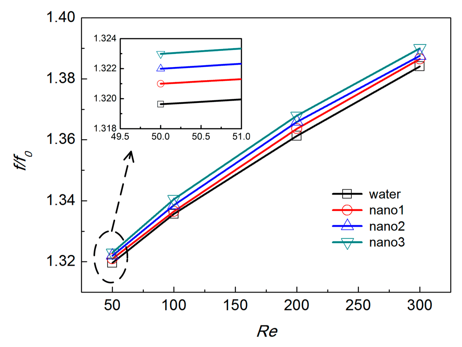
Figure 6 is the variation of
f/f0 in the protruded microchannel with working substances varying from water to nano3.
f/f0 increases with the increase of
Re. For the same
Re,
f/f0 show a small difference among different fluids, while, as the nanofluids concentration increases,
f/f0 increases a bit accordingly. When
Re increases, the above-mentioned differences get obvious.
Figure 7 shows the temperature contours and limiting streamlines on the protruded surface. Flow separates at the tail end of the protrusion, and reattaches quickly in the wake under the effect of the adverse pressure gradient, so the separation bubbles are small. As the nanofluid concentration increases, separation bubbles show little change in the streamwise direction, while the effect of protrusion on flow structure and temperature develops along the spanwise direction, then
f/f0 increases slightly.
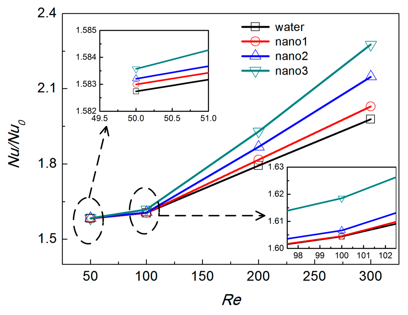
The variation trend of
Nu/Nu0 is more obvious, comparing with that of
f/f0. As are shown in
Figure 8,
Nu/Nu0 of the cases with larger nanofluids concentrations are larger. When
Re is relatively small (
Re = 50 and 100), only a small difference can be observed among different working substances. As
Re further increases to 200 and 300,
Nu/Nu0 of all the cases increase sharply, which is due to the quick development of separation bubbles, and then the differences of
Nu/Nu0 among different working substances also becomes obvious. As are shown in
Figure 7, as nanofluid concentration increases, the effect of separation flow develops along the spanwise direction, enhancing the heat and mass transfer between near wall fluid and the main flow; therefore, the average temperature and temperature gradient decreases, and the temperature of the surfaces in the spanwise direction decreases, obviously, so
Nu/Nu0 of the whole channel increases. Furthermore, this influence is enhanced at larger
Re cases.
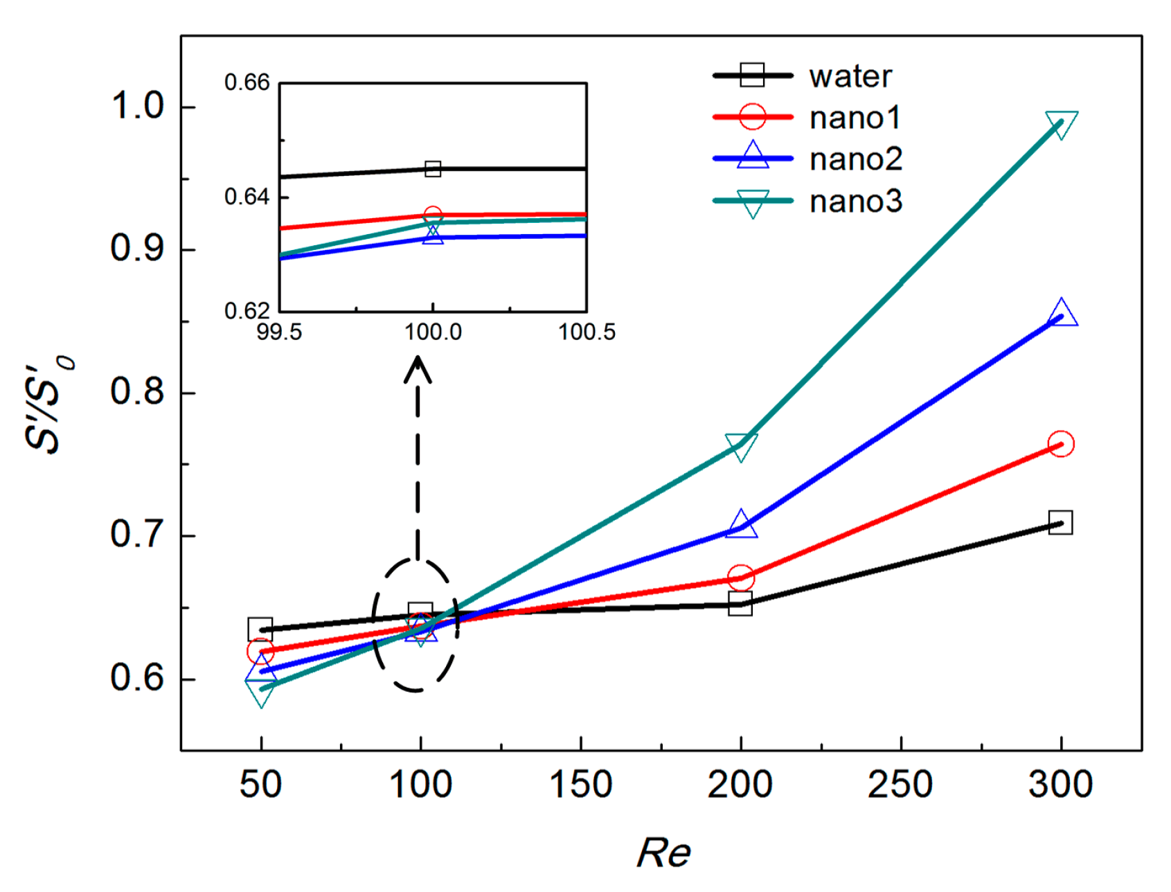
The variation of
S′/S′0 in the protruded microchannel with working substances varying from water to nano3 are shown in
Figure 9. When
Re is 50,
S′/S′0 of the water case is at a maximum, and as nanofluid concentration increases,
S′/S′0 decreases gradually, combining with the results in
Figure 7 and
Figure 8, the variation of
S′/S′0 herein means the influence of
Nu/Nu0 is dominant for small
Re cases. As
Re increases,
S′/S′0 of cases with larger nanofluids concentration increase more quickly, and then
S′/S′0 of nano3 case is maximum at
Re = 200 and 300, which means that the mass flow rate and
f/f0 have combined dominant effects for large
Re cases. As
Re increases, differences of
S′/S′0 among different cases with varied working substances also increase.
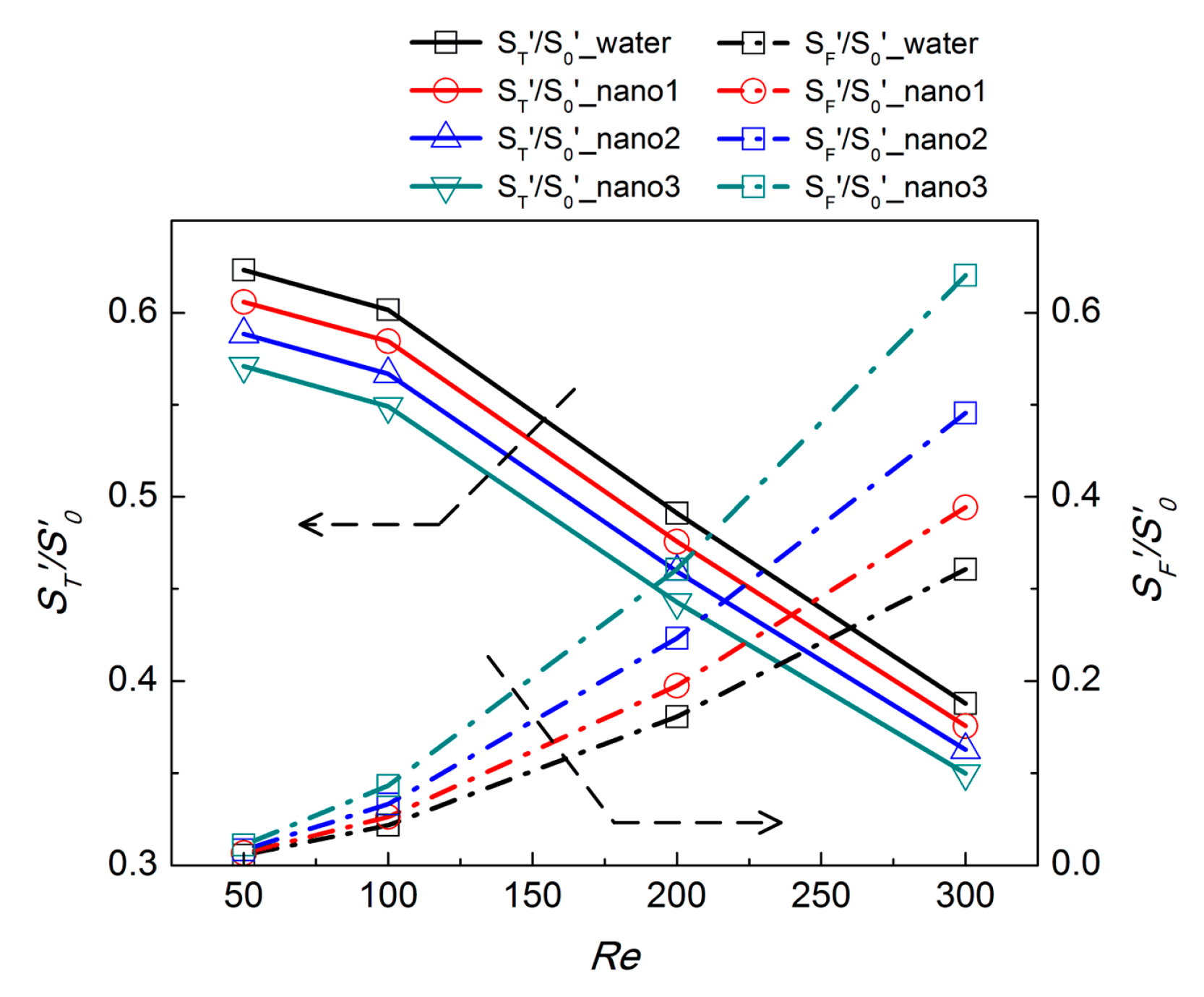
Furthermore,
S′/S′0 consists of the heat transfer irreversibility and the fluid frictional irreversibility, which can be evaluated by
ST′/S′0 and
SF′/S′0, respectively, and due to the large increase in the form drag, the fluid friction induced entropy generation can no longer be negligible [
41], different with that in low flow resistance applications [
43]. The variation of
ST′/S′0 and
SF′/S′0 are shown in
Figure 10 to illustrate the change of
S′/S′0 in detail. For the given
Re, as nanofluids concentration increases,
ST′/S′0 decreases and
SF′/S′0 increases. With the increases of nanofluids concentration, both the thermal conductivity of Al
2O
3-water nanofluids (
Table 2) and
Nu/Nu0 (
Figure 8) increase. Then, based on the Equation (20),
ST′/S′0 decreases. While, with the increases of nanofluids concentration, the density of working substances increases (
Table 2), but
f/f0 (
Figure 7) and mass flow rate also increase, and the change of the latter two parameters are much larger than that of former, then
SF′/S′0 increases. As
Re increases, both
Nu/Nu0 and
f/f0 increase, so
ST′/S′0 decreases, but
SF′/S′0 increases accordingly. The variation of
S′/S′0 is based on the change of
ST′/S′0 and
SF′/S′0, which are all influenced by not only the change of
Nu/Nu0 and
f/f0, but also the physical parameters of the working substances.


