The aim of this section is to develop a unified general model of heat or chemical engine valid as an idealized theoretical scheme for all types of PTF devices. All formulas will be written in the natural units of energy, frequency and temperature such that . The working medium is an electron gas occupying effective single-electron states distributed in two bands A and B. The electrons interact with the cold bath at the temperature T which drives them into the Gibbs state at the same temperature. Another reservoir called hot bath is either a heat bath at the temperature or a chemical bath supplying chemical energy to the electronic system. Both types of hot bath can be described by the universal model of a chemical bath characterized by the temperature and the chemical potentials .
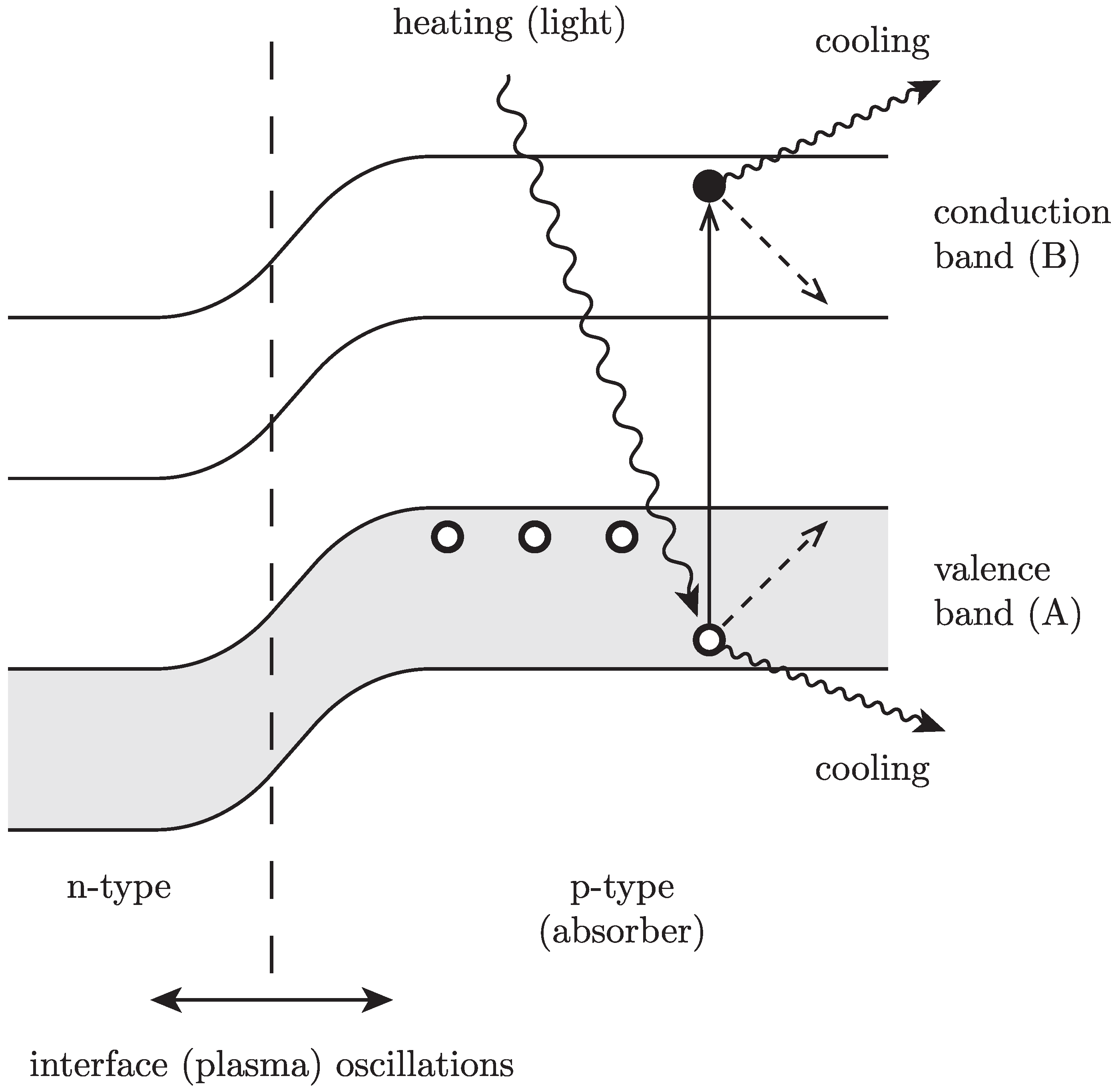
The other important ingredient is the presence of a collective, essentially macroscopic degree of freedom, called work reservoir or piston, which can execute oscillatory motion. In all PTFs, this motion is attributed to plasma oscillations, which are universal phenomena in the presence of freely moving charges in the background of fixed opposite charges and the boundaries separated materials with different charge densities. To generate electric current, which can perform work, one needs a positive feedback mechanism that stimulates the oscillatory motion of the piston at the expense of energy flow from the hot bath.
2.1. Model Hamiltonians
The electrons distributed in two bands
A and
B are described by two sets of the annihilation and creation operators,
,
and
,
, respectively, subject to canonical anticommutation relations. The electrons are treated as non-interacting fermions moving in a self-consistent potential with the unperturbed Hamiltonian:
The system of electrons creates an equilibrium charge distribution which minimizes free energy. The collective perturbation of this distribution produces macroscopic charge oscillations called plasma oscillations with the frequency Ω described by a single collective variable
. The coupling of this collective mode with individual electrons in bands is given by Coulomb and exchange interactions and can be described by a mean field modulation Hamiltonian:
Here, the parameter
ξ absorbs all relevant coupling constants and hence can be interpreted as a shift of the single electron energy in a band
A. The coupling Equation (2) involves only the number of electrons in the
A-band because the total number of electrons in both bands is a constant of motion and hence the number of electrons in
B-band can be eliminated at the cost of an overall shift of the energy scale.
The system of electrons perturbed periodically by the piston interacts with a non-equilibrium environment composed at least of two baths. One of these baths is assumed to be a thermal reservoir at the device ambient temperature
T. We assume also that, practically, this cold bath can cause only
intraband transitions and serves as a dump for a part of the supplied energy. The corresponding interaction Hamiltonian can be written as:
where
are hermitian matrices consisting of operators acting on the baths Hilbert spaces.
The second component of the environment is the source of energy either in the form of heat supplied at the higher temperature
, or chemical energy. In this case, the interaction Hamiltonian reads:
and describes the
interband transitions.
2.2. Markovian Master Equations
A generic quantum open system coupled to a stationary environment is described by the “bare” system Hamiltonians
, the bath Hamiltonian
, and the weak interaction Hamiltonian:
(
S (
R) is a Hermitian system (reservoir) operator) and the stationary state of the reservoir satisfying
The Schroedinger picture Markovian Master equation (MME) for the system reduced density matrix has the following standard form:
where
with
denoting the set of all non-negative Bohr frequencies.
Notice, that
is defined with respect to the renormalized,
physical Hamiltonian
H containing
Lamb-shift corrections. The influence of the reservoir on the relaxation processes is entirely described by the coupling spectrum defined as:
The term in Equation (
7) proportional to
characterizes the dissipation rate of energy
ω into bath, while the term proportional to
is the reverse process of excitation.
The generalization of the form of MME to more complicated interactions like, e.g., Equation (3) or Equation (4) is straightforward.
2.3. Thermal and Chemical Baths
Two particular types of baths are important for the models of PTF—a thermal bath and a chemical bath.
A
thermal bath is described by the Gibbs state at the temperature
T given by the density matrix
The so-called Kubo–Martin–Schwinger condition (KMS) implied by the form Equation (
10) and valid in the thermodynamic limit leads to the following relation (detailed balance) satisfied by the coupling spectrum
Under the condition Equation (
11), the Gibbs state at the same temperature
T is a stationary solution of the MME Equation (
7).
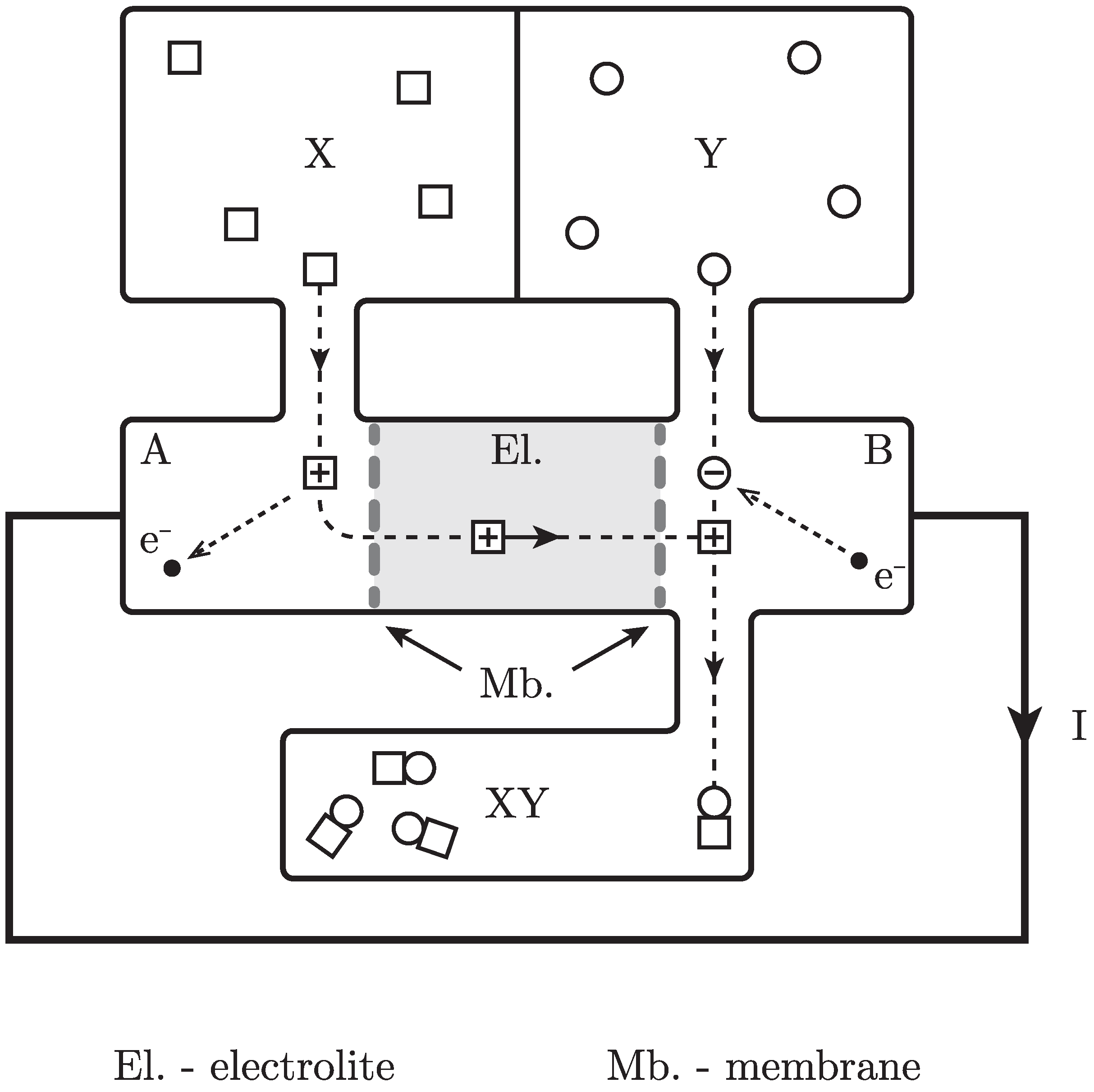
A
chemical bath is a collection of
K separated baths each consisting of many molecules of a given type. The whole bath is described by the density matrix corresponding to the grand canonical ensemble at the temperature
and the chemical potentials
Here,
is the operator describing the number of
j-type molecules in the bath and
is the total Hamiltonian of the chemical bath satisfying
The Condition (
13) means that the molecules in the chemical bath do not undergo chemical reactions unless they became coupled by the quantum system. This coupling can be described by the rotating-wave approximation version of the Hamiltonian Equation (5):
Here,
increases the energy of the system and the operator
describes the possible transitions from higher to lower energy levels of the bath including chemical reactions. One can think about
as a sum of products of operators describing transitions preserving all numbers of molecules, “annihilation operators” corresponding to reactants and “creation operators” corresponding to reaction products, respectively. Hence,
satisfies the following relation
where
are
stoichiometric coefficients, negative for reactants and positive for reaction products. The sum
can be interpreted as the Gibbs free energy released in a single reaction. Obviously, the operator
describes the reverse processes consuming energy from the system. If the operators
commute with all number operators
, then
, no chemical reactions occur, and the bath acts as a purely thermal bath at the temperature
.
Applying again the standard derivation of the MME, one obtains the Equation (
7) with
(
) replaced by the relaxation coefficient:
and
(
) is replaced by the excitation coefficient:
The fictitious dynamics governed by the
extended Hamiltonian and applied to the operators
yields:
Using Equation (
19) and the KMS condition again for the grand canonical ensemble
treated as an “extended” Gibbs state and the “extended” operators
, one obtains the following relation:
which generalizes the detailed balance Condition (
11) to chemical baths. A chemical bath is more general than a thermal one and reduces to the latter for
, hence it will be used as a universal model of the hot bath for PTFs.
2.4. A Generic Model of a Quantum Engine
In the PTF model, the electron gas, interacting with a stationary environment and collective degree of freedom (plasma oscillation), can be considered as a particular example of slowly driving quantum open system. In other words, it can be interpreted as a version of the generic quantum heat engine model introduced in [
6] (compare also [
7]) and successfully used in the context of solar cells [
1] and thermoelectric generators [
2].
In this scheme, the quantum system corresponding to “working medium” interacts weakly with a stationary non-equilibrium environment typically, but not always, consisting of two heat baths at different temperatures. The external periodic driving added to the free Hamiltonian of the system describes the action of a macroscopic piston which supplies and extracts work. If the average net power extracted from the working medium is positive, then the oscillations of the piston are self-sustained (self-oscillations), and the whole system acts as an engine yielding useful work.
Under certain standard assumptions: (i) weak system-environment coupling; (ii) ergodic properties of the stationary environment; (iii) slowly varying
in comparison to the fast internal dynamics; the irreversible evolution of the reduced density matrix
of the working medium satisfies the Markovian master equation (MME) of the following form:
Here,
is the total Hamiltonian of the working medium and
describes the influence of an environment.
If the modulation part
is also “small”, in comparison to
, we can assume that, according to the standard perturbation theory, in the lowest order approximation,
commutes with
. Then, assuming also harmonic oscillations, we can put
where
g is a “small” amplitude of oscillations.
The dissipative generator
obtained by the standard weak coupling limit procedure is a function of the magnitude of perturbation
ξ and can be written as
Under natural ergodic assumptions, the generator
possesses a unique stationary state
satisfying the identities:
where
,
. As discussed in [
6], the power
provided by the engine and the net heat current
supplied by the environment are defined as:
The definitions of the above are consistent with the first and second law of thermodynamics, and the time-dependence of the Hamiltonian is necessary to define work. The stationary average power output given by the time averaging of
reads:
For the reader’s convenience, the following second order approximation with respect to a small parameter
g is derived in the
Appendix (compare [
1]):
where
is the Heisenberg picture counterpart of the Schroedinger picture generator
. If, additionally, the modulation frequency Ω is much higher than the relaxation rate of the observable
M then, we can use the following compact expression
The lowest order Formula (
28) is still consistent with thermodynamics [
1] and is the basic one for the further analysis of PTF. The stationary output power is proportional to the square of the amplitude of piston oscillations, which is a free parameter. This amplitude is determined by the energy flux from the environment and the load attached to the piston, e.g., the resistance, electric motor or battery in the case of PTF.
2.5. MME for the PTF
The general framework of the previous section can be applied to the PTF model described by the Hamiltonians Equations (1)–(4). The first element is the MME generator
computed under the absence of modulation. It is a sum of two generators corresponding to statistically independent processes of intraband transitions induced by the thermal cold bath at the ambient temperature
T and the interband transitions induced by the chemical hot bath characterized by the temperature
and the Gibbs free energy excess
. The detailed structure of the generators is the following:
where the summations in the formulas of the above are performed over the sets of indices:
.
The term in Equations (32) and (33) describes the following intraband processes:
- (a)
Band A (B) electron relaxation from the state k (l) to the state ( ) accompanied by a positive energy release to the heat bath at the ambient temperature;
- (b)
The inverse process of electron transfer from the lower energy state to the higher energy one with the probability suppressed by the Boltzmann factor.
The term in Equation (34) describes the following interband processes:
- (c)
Electron transfer from the higher energy state k in the band A to the lower energy state l in the band B;
- (d)
The inverse process of electron transfer with the probability suppressed or enhanced by suitable Boltzmann factors including chemical energy.
The analysis of the stationary state for the MME governed by the generator Equation (29) is based on the following facts:
- (i)
The intraband thermalization processes governed by Equations (32) and (33) preserve the number of electrons in each band and for a fixed initial numbers of electrons drive the system into a product of two canonical Gibbs states at the temperature T;
- (ii)
The interband transitions described by Equation (34) preserve the total number of electrons but modify the relative occupation of both bands;
- (iii)
Because the number of electrons in a macroscopic PTF device is very large, we can use the equivalence of canonical and grand canonical ensembles to derive the approximate form of the stationary state for ;
- (iv)
Due to the form of the modulation Equation (2), the stationary state of the generator can be obtained from the stationary state of the generator by replacing the single electron energy by .
Taking (i)–(iv) into account, one concludes that the approximate stationary state of the generator
has a form of the product of grand canonical ensembles at the ambient temperature
T but with two different electrochemical potentials
:
The electro-chemical potentials
are determined by the average numbers of electrons in both bands. Therefore, they are functions of the hot bath temperature
, the density of electrons in the material and the load which is attached to the device. This load might be described by the additional generator which takes into account the exchange of electrons between the PTF device and the external circuit. This generator does not depend on
ξ and hence does not explicitly enter the formula for the power output Equation (
28) (see Equation (
24) for the explanation), but contributes to the form of the stationary state. Therefore, the electro-chemical potentials
may be treated as adjustable parameters depending on the external load.
The difference of electro-chemical potentials between bands can be interpreted as the measured voltage
V of the PTF device,
i.e.,
Indeed, the band
A supplies electrons to the external circuit at the higher energy
per electron while the band
B accepts electrons at the lower energy
per electron.
2.6. The Formula for the Output Power
The results of the previous section can be inserted into the general formula for power output Equation (
28). The derivative
is given by
Inserting Equation (37) into Equation (28) and remembering that now
one can simplify the expression for power,
where one uses the fact that the intraband relaxation does not change the number of electrons in each band.
The further computation involves the action of the Heisenberg picture generator on
for the chemical hot bath:
where
and
.
After inserting Equation (
39) into Equation (
38), one can use the properties of quantum grand canonical ensembles Equation (35) and reduce the averages of even products of annihilation and creation fermionic operators into sums of products of the only non-vanishing two-point correlations:
Here,
denotes the quantum average with respect to the state
given by Equation (35), and
and
are the Fermi–Dirac statistical distribution functions:
with
. The straightforward computation yields the leading order term
where
The presence of the factor Equation (
43) in the sum Equation (
42) essentially restricts the range of positive energy differences
which can be replaced in the exponent by a single “average” denoted by
. This leads to the following final formula for the output power:
where
.
A direct consequence of the formula Equation (
44) is the condition for work generation in PTF devices:
Here,
can be interpreted as an
open-circuit voltage because, when the external circuit is closed, the voltage is reduced and the positive output power maintains collective plasma oscillations (positive feedback). These charge oscillations are subsequently rectified by the diode mechanism due to the build-in non-ohmic junctions, which are present in all PTF devices.
For a purely thermal hot bath, the Carnot factor also suggests the interpretation of the Equation (45) in terms of thermodynamical efficiency. A single electron excited from the band B to A requires, on average, of thermal energy extracted from the hot bath. Then, a part of is transformed into useful work, equal at most to per single electron flowing in the external circuit. For a purely chemical hot bath, in principle, the whole Gibbs energy can be transformed into work.
Obviously, for real systems, the efficiency is much smaller than the theoretical bound because heat conductivity and damping of plasma oscillations dissipate a large portion of the supplied thermal and chemical energy.


