How to Construct a Combined S-CO2 Cycle for Coal Fired Power Plant?

1
Beijing Key Laboratory of Multiphase Flow and Heat Transfer for Low Grade Energy Utilization, North China Electric Power University, Beijing 102206, China
2
Key Laboratory of Condition Monitoring and Control for Power Plant Equipment of Ministry of Education, North China Electric Power University, Beijing 102206, China
*
Author to whom correspondence should be addressed.
Entropy 2019, 21(1), 19; https://0-doi-org.brum.beds.ac.uk/10.3390/e21010019
Submission received: 29 November 2018
/
Revised: 22 December 2018
/
Accepted: 23 December 2018
/
Published: 27 December 2018
(This article belongs to the Special Issue Entropy Generation and Heat Transfer)
Abstract
:It is difficult to recover the residual heat from flue gas when supercritical carbon dioxide (S-CO2) cycle is used for a coal fired power plant, due to the higher CO2 temperature in tail flue and the limited air temperature in air preheater. The combined cycle is helpful for residual heat recovery. Thus, it is important to build an efficient bottom cycle. In this paper, we proposed a novel exergy destruction control strategy during residual heat recovery to equal and minimize the exergy destruction for different bottom cycles. Five bottom cycles are analyzed to identify their differences in thermal efficiencies (ηth,b), and the CO2 temperature entering the bottom cycle heater (T4b) etc. We show that the exergy destruction can be minimized by a suitable pinch temperature between flue gas and CO2 in the heater via adjusting T4b. Among the five bottom cycles, either the recompression cycle (RC) or the partial cooling cycle (PACC) exhibits good performance. The power generation efficiency is 47.04% when the vapor parameters of CO2 are 620/30 MPa, with the double-reheating-recompression cycle as the top cycle, and RC as the bottom cycle. Such efficiency is higher than that of the supercritical water cycle power plant.
1. Introduction
Coal fired power generation accounts for nearly 32% of the world’s total electricity production [1]. However, this application is a concern due to environmental pollution and carbon dioxide emissions [2,3]. Thus, a clean, efficient, and flexible coal fired power plant is attractive for power generation. S-CO2 cycle has extensive application in power generation, such as concentrating solar power generation [4,5,6], nuclear power generation [7,8,9], waste heat utilization of gas turbine [10,11,12] due to its high efficiency [13,14], simple system [10,15], and compact layout [16,17]. These advantages make it attractive to apply a S-CO2 cycle to coal fired power generation, but this system faces a residual heat problem.
The main reason for this problem is that the cycle has a good regenerative effect, leading to a high CO2 temperature at the boiler inlet. For example, recompression cycle is a commonly used S-CO2 cycle, when the double reheating recompression cycle is applied, the CO2 temperature at boiler inlet is about 510 °C [18,19]. While this temperature is about 340 °C in the double reheating supercritical water cycle [20]. The great temperature difference means a large amount of residual heat in the tail flue at S-CO2 coal fired power plant, which restricts the boiler efficiency. Therefore, how to solve this problem to get a high boiler efficiency is a key issue in this field.
The solutions for this problem can be divided into three categories: (1) adding flue gas cooler [21,22,23], (2) raising air temperature [18,24,25], (3) constructing combined cycle [26,27,28].
The concept of adding flue gas cooler is to extract a part of low temperature CO2 flow rate from S-CO2 cycle into the tail flue to absorb residual heat [18]. It is found that thermal efficiency is decreased as increasing of the extracted flow rate since the additional heat is added to the cycle. However, adding flue gas cooler still has an efficiency benefit over no flue gas cooler due to lower compression work for the compressor system.
Residual heat can be reduced by raising air temperature in air preheater. However, there are two limitations to this application. The first limitation is that the heat capacity of air is smaller than that of flue gas. Thus, with increase of air temperature, the temperature difference between flue gas and air decreases, leading to a sharply increased volume of air preheater. Another limitation is that the high-temperature air preheater is difficult to manufacture, thus a traditional tri-sector air preheater is not suitable for this case.
If we want to keep a high cycle thermal efficiency while maintain the air preheater compatible within the present engineering experience, constructing the combined cycle is a promising method. Johnson et al. [26] propose using a Rankine cycle to absorb residual heat. However, this scheme has lost some advantages of the S-CO2 cycle, such as simple system and compact layout. McClung et al. [27] suggest absorbing residual heat through two series recompression cycles. Both top and bottom cycles are S-CO2 cycles. Sun et al. [28] explore the power generation efficiency of applying different S-CO2 bottom cycles to absorb residual heat, such as a simple recuperated cycle, partial cooling cycle, recompression cycle, etc. It is found that the suitable bottom cycle is different for different turbine inlet temperatures.
From the present research, it is shown that the analysis of combined cycle for S-CO2 coal fired power generation is based on the first law of thermodynamics. While we should pay more attention to the exergy destruction in residual heat transferring process to highlight the different bottom cycles. This is because the boiler efficiency is guaranteed when the residual heat is fully absorbed by the bottom cycle. However, exergy destruction of different bottom cycles in residual heat absorption process will be different, which restricts the comparison between different bottom cycles. In this paper, we attempt to answer the question that how to choose a highly efficient bottom cycle. This paper is organized as follows. Section 2 describes the mathematical model. Section 3.1 explains the causes of residual heat problem. Section 3.2 proposes the exergy destruction control strategy during residual heat recovery and explains the rationality of this strategy. In Section 3.3, five S-CO2 bottom cycles are analyzed to reveal their differences in thermal efficiency (ηth,b), bottom cycle heater inlet temperature (T4b), etc. It is found that although the cycles are different, the strategy in Section 3.2 can be achieved by adjusting T4b. In Section 3.4, two kinds of better performance combined S-CO2 cycles are detailed analyzed in which the top cycle is double reheating recompression cycle (DRH), the bottom cycle is recompression cycle (RC), and partial cooling cycle (PACC), respectively.
2. System Description and Methods
2.1. S-CO2 Cycle Description
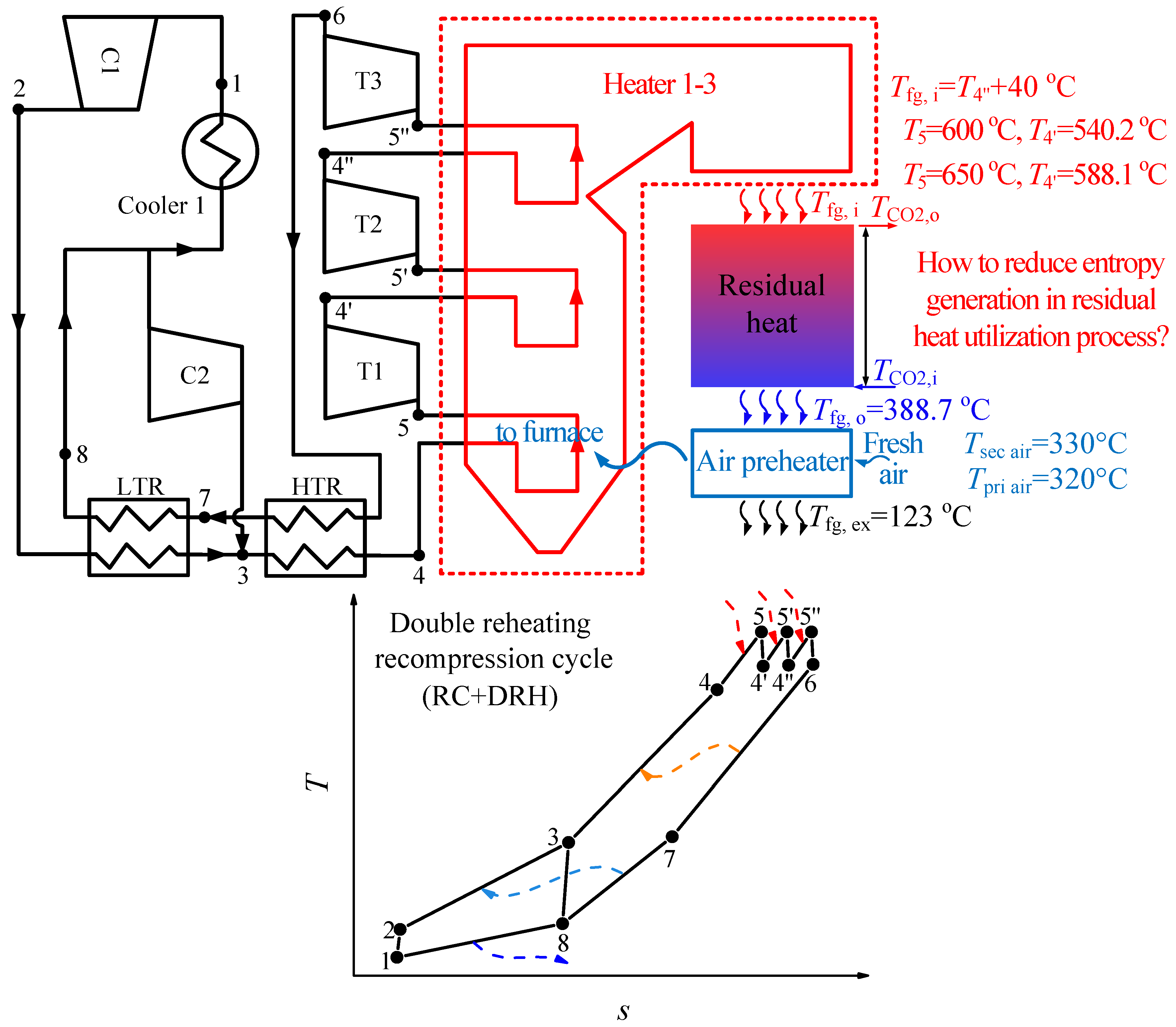
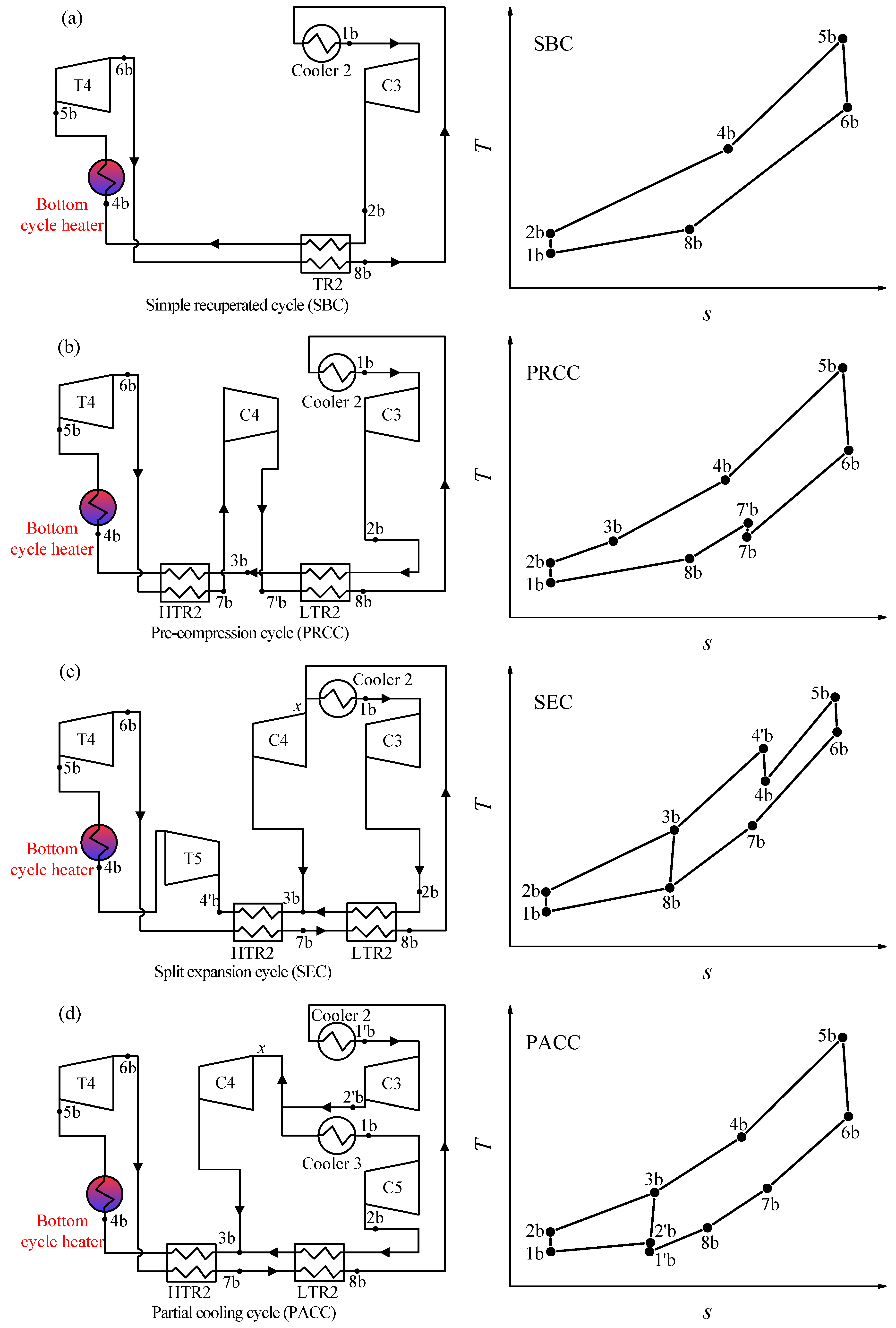
The combined cycle consists of the top cycle and bottom cycle. In this paper, the double reheating recompression cycle (RC + DRH) is selected as the top cycle, due to its high efficiency [18,24]. The flow diagram and T-s diagram of RC + DRH is shown in Figure 1. Five S-CO2 cycles are selected as the bottom cycle, such as simple recuperated cycle (SBC), pre-compression cycle (PRCC), recompression cycle (RC), split expansion cycle (SEC), partial cooling cycle (PACC), as shown in Figure 2 and Figure 3. Since there are many S-CO2 cycles involved, the characteristics of each cycle are introduced.
For the top cycle, the CO2 flow stream after high-temperature recuperator (HTR) enters the boiler and converts thermal energy into power by three turbines (T1–T3). Then low-pressure CO2 from the outlet of T3 transmits heat to high-pressure CO2 through HTR and LTR (low-temperature recuperator). Here the following flow assignment should be highly focused due to the unique characteristics of the recompression cycle can be reflected by this layout: the flow from LTR is split into two streams, one stream needs to flow through cooler 1 into compressor 1 (C1). The other stream flows into the auxiliary compressor (C2), then enters the high-pressure side outlet of LTR (point 3). This flow assignment reduces the heat released into the environment by splitting part of CO2 directly into C2, which is an important reason for the high efficiency of recompression cycle. Table 1 summarized the parameters from the above calculation.
There are five kinds of bottom S-CO2 cycles, and a brief introduction is as follows:
Simple recuperated cycle (SBC): The SBC is one of the simplest S-CO2 cycles, shown in Figure 3a. There is only one regenerator. Due to the specific heat capacity difference between the cold and hot sides of the regenerator, the bottom cycle heater inlet temperature (T4b) is lower which leads to heat absorption in heat source, more under the unit mass flow rate.
Pre-compression cycle (PRCC): Different from SBC, the CO2 at the outlet of turbine 4 (T4) is at the subcritical state. This will increase the enthalpy drop in the turbine. Meanwhile, the regenerator is divided by two, and the subcritical state CO2 is compressed to the supercritical state by an additional compressor (C4), shown in Figure 3b. Although the outlet temperature of T4 decreased with the enthalpy drop of T4 increased, PRCC and SBC have similar bottom cycle heater inlet temperature (T4b). Thus, the heat absorption of both cycles is nearly the same, but more work is produced by PRCC, then the efficiency of PRCC is slightly higher than that of SBC (shown in Figure 5a,b).
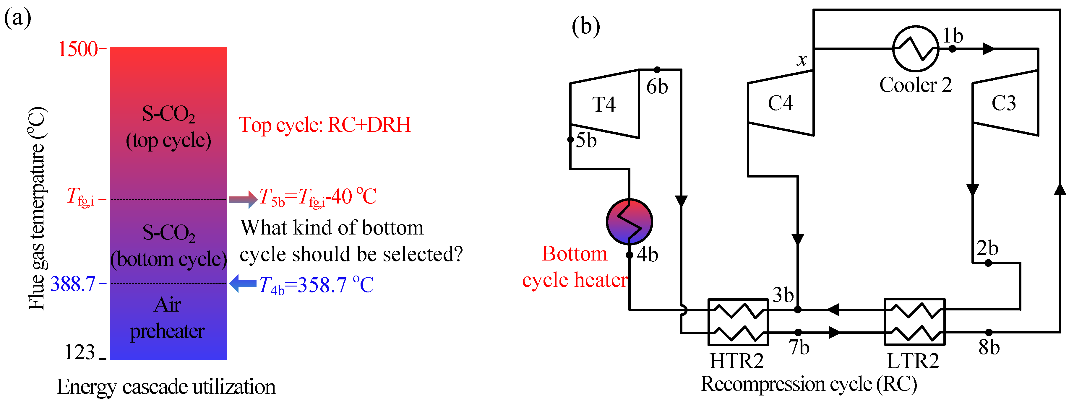
Recompression cycle (RC): RC is the foundation of RC + DRH (see Figure 2b). It can be referred to the description of the top cycle.
Split expansion cycle (SEC): SEC is evolved by RC, shown in Figure 3c. The only difference is the bottom cycle heater is added between the turbine 4 (T4) and turbine 5 (T5). Thus, the inlet temperature of T5 is lower, leading to a lower thermal efficiency than RC (see Figure 5a).
Partial cooling cycle (PACC): PACC has the characteristics of PRCC and RC, shown in Figure 3d. First, the outlet parameter of turbine 4 (T4) is the subcritical state, similar to PRCC. Secondly, the CO2 flow rate is divided before entering the cooler 3, similar to RC. Thus, the efficiency of PACC is somewhere between PRCC and RC (see Figure 5a).
Table 2 summarized the calculated parameters for the bottom cycle.
2.2. Thermodynamic Model for S-CO2 Cycle
Different cycles have different characteristics. However, all of them can be simulated by the classical method. The following shows the simulation method based on RC for per unit total mass flow rate.
Isentropic efficiency and power output for turbine 4 (T4) are
Isentropic efficiency and power output for C3/C4 are
In Equations (1)–(3), the subscripts s represents isentropic condition, xb is the mass flow fraction, which is defined as the ratio of mass flow rate in C4 to total mass flow rate, and h stands for enthalpy.
Energy conservation equation for LTR and HTR are given by
The heat absorption by bottom cycle heater (qrb) and heat dissipated by cooler 2 (qc2) are
The cycle thermal efficiency is
2.3. Calculation Method of Residual Heat
In respect of flue gas energy distribution, the high temperature region is absorbed by top cycle, middle temperature region (residual heat region) is absorbed by bottom cycle, low temperature region is absorbed by air preheater (see Figure 2a). For top cycle and air preheater, when the total output power and air temperature are fixed, the amount of heat absorbed from the boiler is determined. Then, the remaining heat in boiler is the residual heat, which should be absorbed by the bottom cycle.
The boiler efficiency (ηb) is calculated as [29]
where qi is the heat loss. For large-scale coal fired boiler, except q2 (exhaust gas heat loss), the other heat losses can be set as constants where q3 = 0 (incomplete chemical combustion heat loss), q4 = 0.6 (unburned carbon heat loss), q5 = 0.2 (furnace exterior heat transfer loss), q6 = 0.06 (enthalpy variation loss of ash and slag). q2 is calculated as
where αair is the excess air ratio, hair is the air enthalpy at environment temperature. QLHV is the lower heating value of coal (QLHV = 23442 kJ/kg, see Table 3 for coal parameters).
When assuming the exhaust gas temperature (Tfg,ex) is equal to the gas temperature at the bottom cycle heater inlet (Tfg,i), Tfg,ex = Tfg,i (see Figure 1), the equivalent boiler efficiency at bottom cycle heater inlet (ηb,fg,i) can be calculated. Then, the coal consumption (mcoal) is
where Qrt is the heat absorbed by heater 1–3.
The residual flue gas heat is calculated as
where mfg is the mass flow rate of flue gas, which is the sum of coal consumption mcoal and the mass flow rate of air mair (mfg = mcoal + mair). Based on the Qrb, the mass flow rate of bottom cycle can be calculated according to Equation (6). Then the actual boiler efficiency can be calculated according to the set Tfg,ex = 123 °C. The power generation efficiency ηe is
where ηp is the pipeline efficiency (evaluates the heat loss through the pipeline between each component) [30,31] and ηg is the generator efficiency (see Table 1 for the values). The simulation in this paper is developed using FORTRAN language. Physical properties of CO2 come from REFPROP [32].
3. Results and Discussion
3.1. Causes of Residual Heat Problem
S-CO2 coal fired power generation system is shown in Figure 1. There is a large amount of residual heat in the tail flue. The residual heat is caused by two effects:
(1) The CO2 temperature is high in the tail flue: differences of heating surface layout between this paper and [28] is that in this paper the preheater in tail flue is eliminated. This change means that the CO2 at the outlet of HTR (point 4) enters the furnace directly rather than the tail flue. Thus, one of the reheater inlet temperature (T4′, T4″) is the lowest CO2 temperature in the tail flue. T4′ and T4″ can be calculated by the following equation
where ηT1,s and ηT2,s are the turbine isentropic efficiency, h is the enthalpy. To solve the above equation, it is also necessary to know the turbine inlet pressure [18]
Based on Equations (14) and (15), T4′, T4″ can be calculated. For example, when T5 = 600 °C, P5 = 30 MPa, T4′ = 540.2 °C, T4″ = 542.8 °C, and T5 = 650 °C, P5 = 30 MPa, T4′ = 588.1 °C, T4″ = 590.4 °C. Therefore, the lowest CO2 temperature (T4′, T4″) in the tail flue is much higher than the lowest water temperature for the water-steam Rankine cycle which is usually around 340 °C [20]. Here T4′ is considered as the lowest CO2 temperature in the tail flue. When T4′ is obtained, the flue gas temperature after the S-CO2 cycle (Tfg,i) can be calculated according to the pinch temperature (ΔTp,fg,i) between the flue gas and CO2 at point 4′
where ΔTp,fg,i = 40 °C in this work. Based on Equation (16), when T4′ = 540.2 °C, Tfg,I = 580.2 °C, and T4′ = 588.1 °C, Tfg,I = 628.1 °C.
(2) The air temperature is limited in the air preheater: tri-sector regenerative air preheater is widely used in large-scale coal fired power system. In the air preheater, flue gas heat is absorbed by primary air and secondary air. However, considering the cost and security issues [33], air temperature cannot be increased without limitation. In this paper the primary air temperature (Tpri air) is set at 320 °C, the secondary air temperature (Tsec air) is set at 330 °C, which is in line with existing engineering experience. Based on above assumption and other parameters shown in Table 1, the flue gas temperature at the inlet of air preheater can be determined by energy conservation equation
where Qflue gas is the heat released by flue gas, Qpri air, Qsec air are the heat absorbed by primary air and secondary air. The heat of flue gas and air can be calculated by the temperature difference
where mfg is the mass flow rate of flue gas, Tfg,o is the flue gas temperature at the inlet of air preheater, cp,fg is the heat capacity of flue gas, Tfg,ex is the exhaust temperature of flue gas.
where αpri is the primary air flow rate ratio, Tpri air,in is the primary air temperature at the inlet of air preheater.
where αsec is the secondary air flow rate ratio, Tsec air,in is the secondary air temperature at the inlet of air preheater.
Tfg,o can be obtained from Equations (17)–(20) which is 388.7 °C. This temperature is far below Tfg,i which are 580.2 °C and 628.1 °C when turbine inlet temperatures (T5) are 600 °C and 650 °C, respectively. The great temperature difference between Tfg,i and Tfg,o reflects that there is a lot of residual heat in the tail flue. If the residual heat cannot be efficiently absorbed, the boiler efficiency will be reduced due to the extra heat is discharged into the environment without being used. This problem can be called residual heat problem. Thus, how to efficiently solve this problem is a key issue for S-CO2 coal fired power generation. In this paper, we present a preliminary analysis solving this problem by constructing the combined cycle from the perspective of reducing exergy destruction of the heat transfer. The detailed analysis is shown in Section 3.2.
3.2. Exergy Destruction Control Strategy during Residual Heat Recovery
The combined cycle is constructed where the top cycle is the double reheating recompression cycle and the bottom cycle is the five different S-CO2 cycles (absorbing residual heat). Here, not only do we want the residual heat can be absorbed, but we also hope that the exergy destruction in residual heat absorption process is equal and minimum when comparing different bottom cycles. Exergy destruction (I) in the heat transfer process is
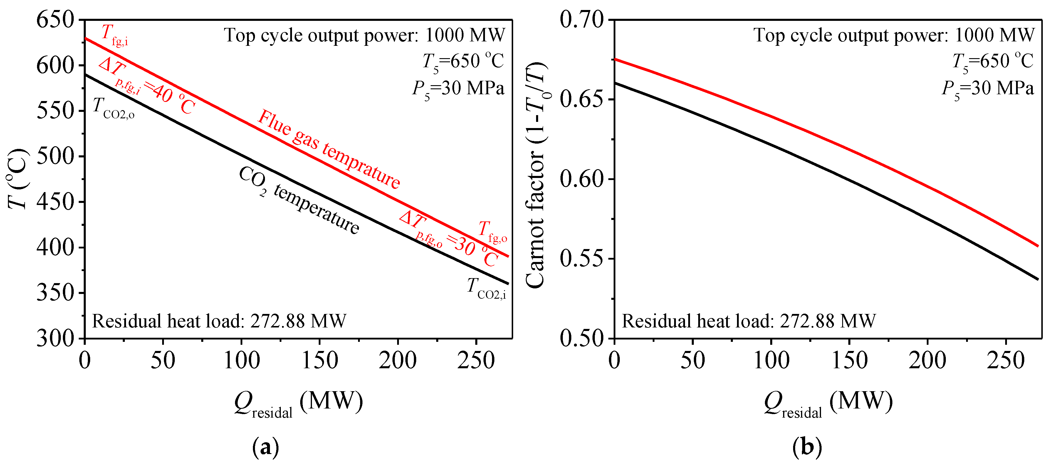
where T0 is the environment temperature, Q0 is the heat transfer quantity between the flue gas and CO2, Tfg, TCO2 is the flue gas and CO2 temperature. Exergy destruction is caused by the temperature difference between flue gas and CO2. The above relationship also can be expressed by the integrated-average temperature difference (ΔTave)
Based on the analysis in [34], I and ΔTave share an exact linear relationship. Therefore, the exergy destruction in the heat transfer process is reduced to reduce the heat transfer temperature difference. In Equation (22), the represents the enclosed area formed by the flue gas temperature and CO2 temperature curves shown in Figure 4a. Thus, the effective way to reduce exergy destruction is to reduce the integrated-average temperature difference which is directly proportional to the enclosed area in T-Q chart. In Section 3.1, it is found that the inlet and outlet flue gas temperature of the bottom cycle heater (Tfg,i, Tfg,o) can be obtained. Meanwhile, in bottom cycle heater, the specific heat capacity of flue gas and CO2 is nearly constant, because the operation parameters are far from the critical region. Under such conditions, it is suggested that the CO2 temperature is to approach flue gas temperature to reduce the enclosed area. However, this approach should be limited, to keep a reasonable heat exchanger area. Here the pinch temperature at the inlet and outlet of bottom cycle heater are set: ΔTp,fg,I = 40 °C, ΔTp,fg,o = 30 °C. This matching relationship between flue gas and CO2 ensures the efficient utilization of residual heat which can be called the exergy destruction control strategy during residual heat recovery. The Carnot factor versus residual heat diagram is also used to illustrate the exergy destruction due to the heat transfer, shown in Figure 4b. The area between the curves in diagram represents the exergy destruction [35,36,37]. It is shown that, under such strategy, exergy destruction can be uniformly distributed and controlled. The next step is to explore what kind of S-CO2 cycle is suitable as the bottom cycle for S-CO2 coal fired power generation system based on this strategy.
3.3. Analysis of Five S-CO2 Bottom Cycle
Five S-CO2 cycles have been introduced in Section 2.1 (shown in Figure 2 and Figure 3). In this section, these S-CO2 cycles are explored to reveal which is the most suitable as the bottom cycle when ensuring the exergy destruction control strategy during residual heat recovery. Here, thermal efficiency of bottom cycle (ηth,b) and CO2 temperature at the inlet of bottom cycle heater (T4b) should be highly concerned.
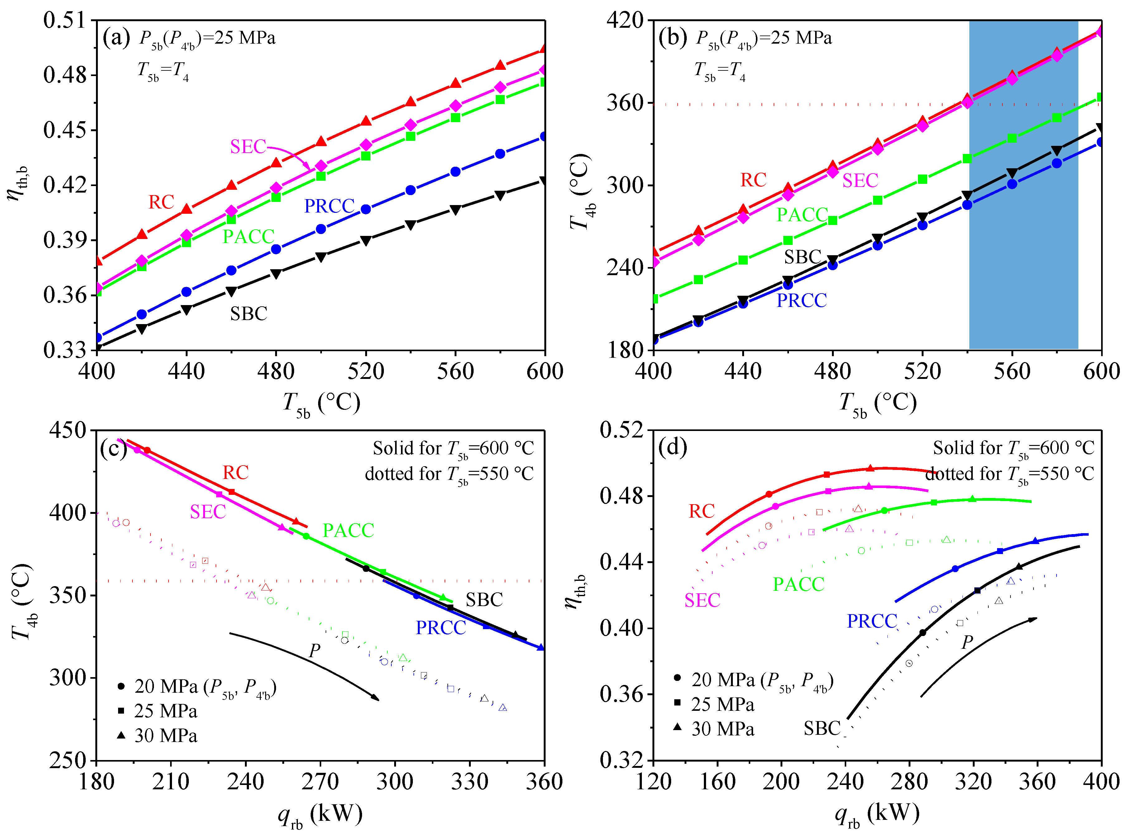
Different S-CO2 cycles have different thermal efficiency: A higher ηth,b, means more work is transformed by residual heat and less heat is released into the environment, due to the total amount of residual heat is fixed. From Figure 5a, it is shown that, under the design condition (see Table 2), the thermal efficiency of the recompression cycle (RC) is better than that of other S-CO2 cycles. The differences of ηth,b among different S-CO2 cycles is very obvious. For example, when T5b = 600 °C, P5b = 25 MPa, the ηth,b of RC is 49.41%, which is 1.80% higher than the ηth,b of PACC and 7.12% higher than the ηth,b of SBC. A question is driven by such a great difference in ηth,b: if RC is the best cycle as the bottom cycle? The answer is no, because, besides the bottom cycle efficiency, the exergy destruction of residual heat should also be considered.
The exergy destruction of residual heat is decided by T4b: Another key parameter is T4b, the matching relationship between flue gas and CO2 is determined by T4b. From Figure 4a it can be seen that the exergy destruction in bottom cycle heater can be related to four parameters (TCO2,o, Tfg,i, Tfg,o, TCO2,i). When the residual heat is absorbed by bottom cycle, TCO2,o = T5b, TCO2,I = T4b. Among the four parameters, T5b can be solved by top cycle. Tfg,i is connected with T5b according to ΔTp,fg,i. Tfg,o can be calculated from the energy conservation equation in air preheater. Thus, the exergy destruction of residual heat is mainly decided by T4b. However, different S-CO2 cycles have different T4b. If we want to keep a smaller exergy destruction, that is to ensure the relationship of Tfg,I = TCO2,o + 30 °C, then T4b should be kept at 358.7 °C. As shown in Figure 5b, T4b of RC and SEC is higher than this constant value under the suitable operating temperature range of T5b (see light blue area), and T4b of the other cycles are lower than this constant value. Thus, T4b should be adjusted to meet the exergy destruction control strategy during residual heat recovery.
T4b can be affected by many variables, such as turbine and compressor isentropic efficiency, regenerator pinch temperature, cooler outlet, and turbine inlet parameters. However, isentropic efficiency and pinch temperature are restricted by the design and manufacture level of components. The cooler outlet parameters should be close to the critical point, to lower the compressor power. Therefore, T4b is actually affected by turbine inlet parameters. For turbine inlet parameters (T5b, P5b), T5b is determined by top cycle, so turbine inlet pressure (P5b) is needed to be highly concerned. Figure 5c shows the relationship between T4b and P5b, it can be seen that with increase of P5b, T4b can be effectively reduced. Meanwhile, the heat absorbed by the bottom cycle heater (qrb) is increased due to the temperature difference of T5b and T4b is increased. According to this feature, T4b of all S-CO2 cycles can be adjusted to a certain value by adjusting P5b to realize a better matching between the flue gas and CO2 in bottom cycle heater.
Based on the above analysis, there is no need to have a further analysis of some S-CO2 cycle owing to their poor performance, such as SBC and PACC. For both of them, in order to maintain T4b = 358.7 °C, P5b should be decreased. With the decrease of P5b, the thermal efficiency of SBC and PRCC is sharply reduced as shown in Figure 5d. For example, PACC and PRCC have an intersection point with the line of T4b = 358.7 °C respectively when T5b = 600 °C, shown in Figure 5c. The intersection point represents the exergy destruction satisfying the exergy destruction control strategy, shown in Figure 4. Under such circumstance, the ηth,b (PRCC) = 42.96%, the ηth,b (PACC) = 47.67% shown in Figure 5d. The huge efficiency difference means that while absorbing the same residual heat, PACC transformed more work. Due to all output work is exergy, thus, compared with PRCC, PACC not only reduces the exergy destruction in the process of absorbing residual heat but also converts the absorbed residual heat into more exergy. The same method can be applied to the comparison between PACC and SBC. The results show that the efficiency of PACC is 6.72% higher than that of SBC. So, based on the above analysis, performance of PRCC and SBC is inferior to that of PACC. Meanwhile, another comparison process is performed between the SEC and RC. T4b is similar between SEC and RC, but the efficiency of RC is higher than that of SEC. Thus, from the perspective of thermal efficiency, RC is better than SEC. Finally, the PACC and RC are selected as the promising bottom cycle to have a further analysis.
3.4. Analysis of Two Combined S-CO2 Cycles
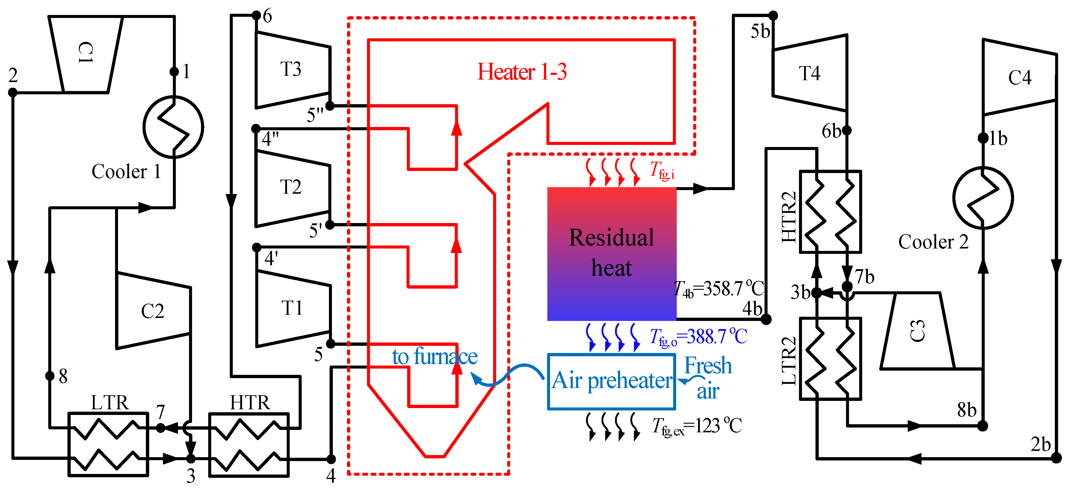
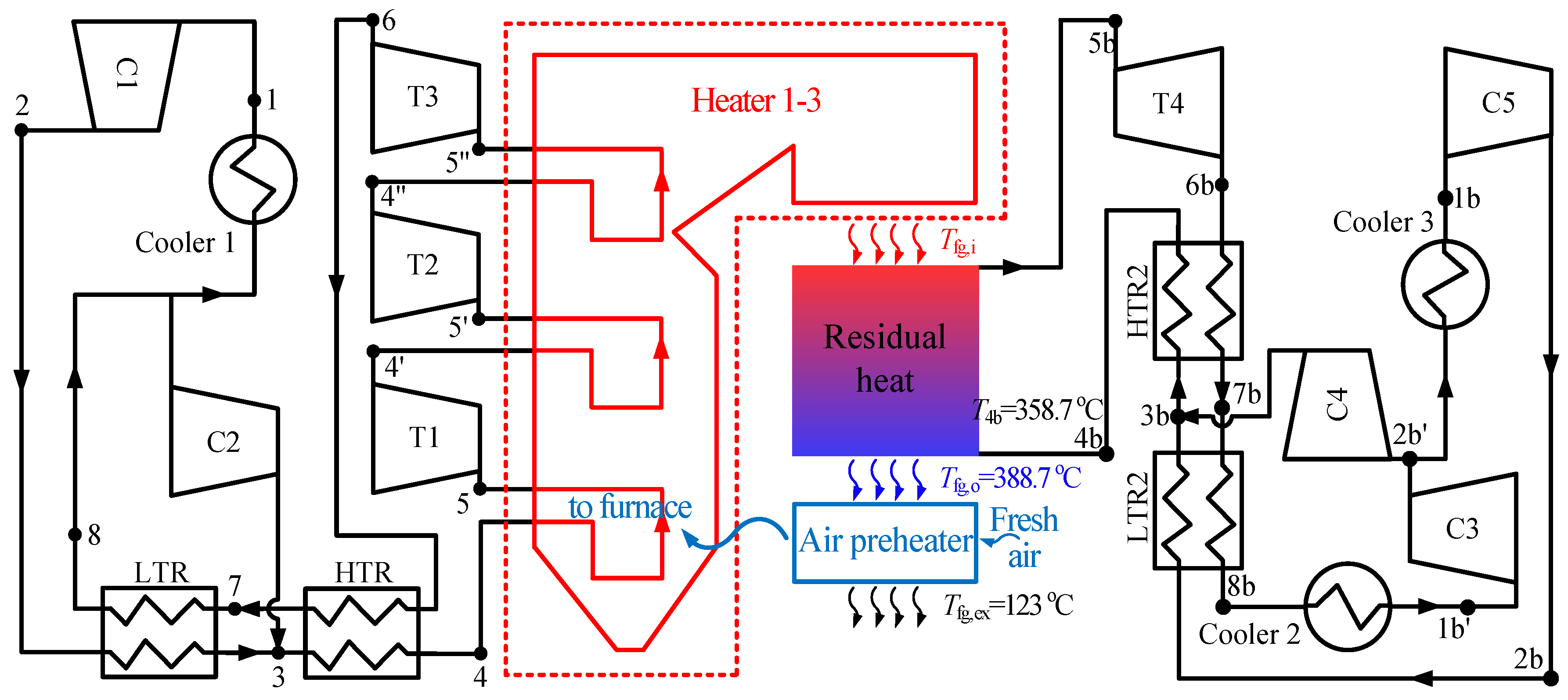
Two combined S-CO2 cycles have been constructed as shown in Figure 6 and Figure 7. The first combined cycle is called as RC + DRH + RC. RC + DRH is the top cycle which means double reheating recompression cycle, RC is the bottom cycle which means recompression cycle. The second combined cycle is called as RC + DRH + PACC. Compared with RC + DRH + RC, the difference is the bottom cycle changed from RC to PACC.
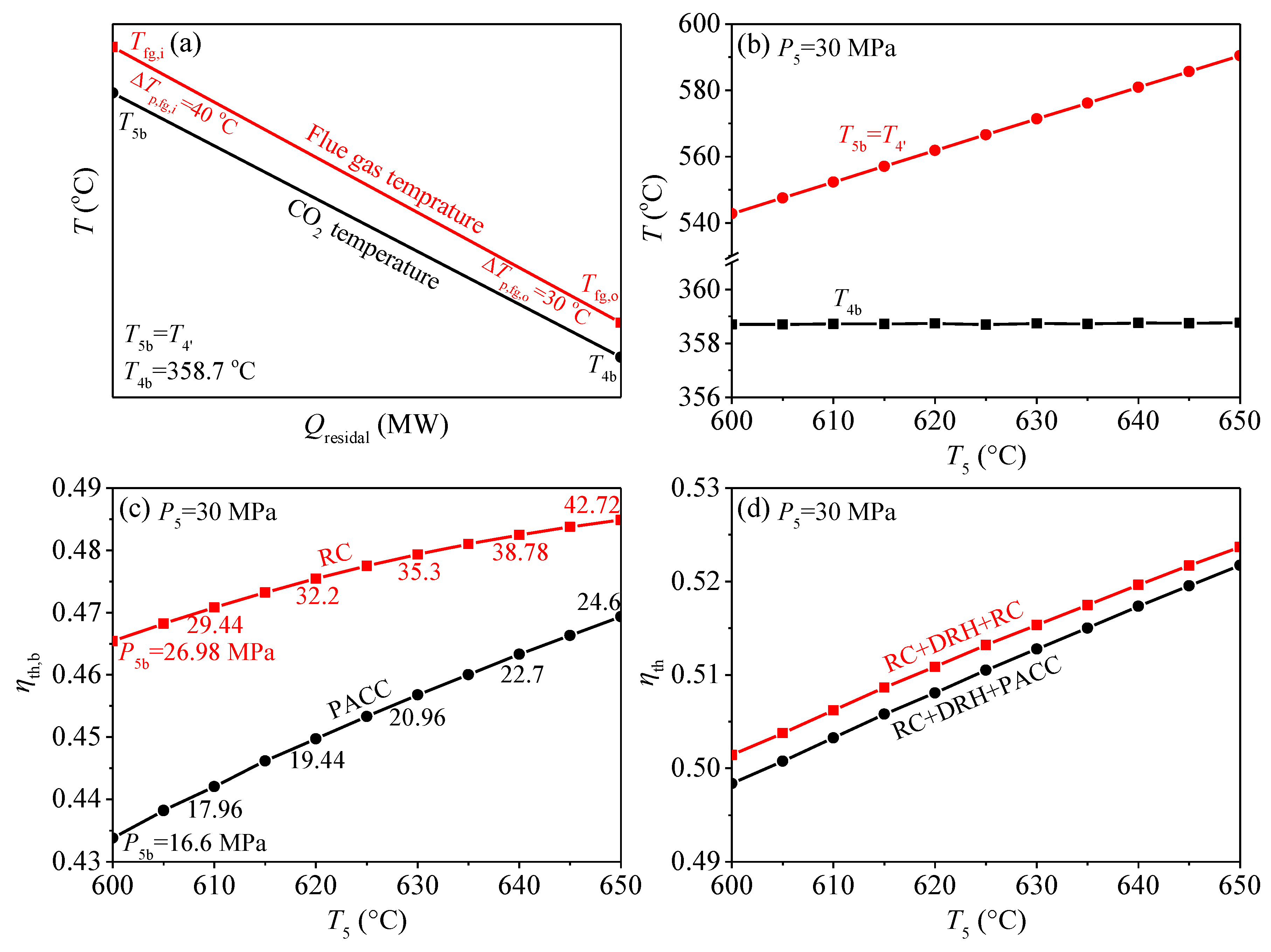
In this section, the exergy destruction control strategy during residual heat recovery is also ensured, shown in Figure 8a. Under this condition, the characteristics of the two combined cycles are compared. Figure 8b shows the relationship between some key point temperatures (T5b, T4′, T4b) and the turbine inlet temperature (T5). With increase of T5, T5b increases, meanwhile, T4b remains unchanged. Keeping T4b constant means that the exergy destruction of the residual heat is controlled in the heat transfer process. In order to ensure T4b unchanged, P5b should be increased, and qrb increased with P5b increased, then the residual heat is effectively absorbed. Temperature relationships in Figure 8b do not distinguish which bottom cycle to apply, it can be considered as the computing boundary condition for the bottom cycle. The calculation results for two combined cycles are shown in Figure 8c,d. Figure 8c shows the bottom cycle thermal efficiency of RC and PACC. To keep the exergy destruction control strategy during residual heat recovery, P5b of RC and PACC is increased. Under such condition, the bottom cycle thermal efficiency of RC is higher than that of PACC. The final combined cycle thermal efficiency is shown in Figure 8d. Similarly, the thermal efficiency of RC + DRH + RC is higher than that of RC + DRH + PACC. Can such a result indicate that the RC should be selected as the bottom cycle? It still cannot come to such a conclusion. To answer this question, Figure 8c should be reviewed again. Figure 8c not only shows the thermal efficiency of the two bottom cycles, but also lists the needed P5b to ensure T4b = 358.7 °C. It is shown that P5b increases with T5. When T5 increased from 600 °C to 650 °C, in order to fully absorb residual heat, P5b increased from 26.98 MPa to 42.72 MPa for RC, and 16.6 MPa to 24.6 MPa for PACC. High pressure of P5b for RC has exceeded engineering experience, such as 42.72 MPa. Therefore, the application of two combined cycles can be divided according to the limitation of materials. For example, when T5 = 620 °C, the thermal efficiency and power generation efficiency of RC + DRH + RC are 51.08% and 47.04% respectively. When T5 = 650 °C, the thermal efficiency and power generation efficiency of RC + DRH + PACC are 52.17% and 48.04% respectively. This result reflects the efficiency benefits of the combined S-CO2 cycle. Thus, even though the proposed cycle is complex, it is still necessary for the field of S-CO2 coal fired power generation. We are also looking for methods to simplify the power system to make it easier to install and manage.
4. Conclusions
The residual heat problem is one of the major issues for limiting the application of S-CO2 cycle in coal fired power generation. In this paper, the combined cycle is constructed to solve this problem. The main conclusions are drawn as follows:
- The exergy destruction control strategy during residual heat recovery is proposed which can be set as the boundary condition for different bottom cycles comparison. The purpose of this strategy is to ensure that the exergy destruction in residual heat absorption process is equal and minimum when comparing different bottom cycles.
- Five S-CO2 bottom cycles are simulated. It is shown that different S-CO2 cycles exhibit different characteristics. In order to ensure the exergy destruction control strategy during residual heat recovery, CO2 temperature at the inlet of bottom cycle heater (T4b) should be adjusted by tuning the turbine inlet pressure of bottom cycle (P5b).
- When the top cycle is a double reheating recompression cycle (RC + DRH), the recompression cycle (RC) and partial cooling cycle (PACC) are suitable as the bottom cycle due to their better performance. Meanwhile, the RC + DRH + RC and RC + DRH + PACC are suitable for different temperature regions. It is recommended that when turbine inlet temperature of top cycle (T5) is 600–630 °C, RC + DRH + RC is more suitable, when T5 is 630–650 °C, RC + DRH + PACC should be proposed.
Author Contributions
The work is conducted and wrote by E.S., H.H., H.L., and C.L., under the supervision of J.X. All authors have read and approved the final manuscript.
Funding
This research was supported by the National Key R&D Program of China (2017YFB0601801), the Science Fund for Creative Research Groups of the National Natural Science Foundation of China (51821004) and the Fundamental Research Funds for the Central Universities (2018ZD02).
Conflicts of Interest
The authors declare no conflict of interest.
References
- Conti, J.; Holtberg, P.; Diefenderfer, J.; LaRose, A.; Turnure, J.T.; Westfall, L. International Energy Outlook 2016 with Projections to 2040; Office of Energy Analysis; USDOE Energy Information Administration (EIA): Washington, DC, USA, 2016. [Google Scholar]
- Sathre, R.; Gustavsson, L.; Le Truong, N. Climate effects of electricity production fuelled by coal, forest slash and municipal solid waste with and without carbon capture. Energy 2017, 122, 711–723. [Google Scholar] [CrossRef]
- Liu, Z.; Guan, D.; Wei, W.; Davis, S.J.; Ciais, P.; Bai, J.; Peng, S.; Zhang, Q.; Hubacek, K.; Marland, G. Reduced carbon emission estimates from fossil fuel combustion and cement production in China. Nature 2015, 524, 335. [Google Scholar] [CrossRef] [PubMed]
- Wang, K.; He, Y.; Zhu, H. Integration between supercritical CO2 Brayton cycles and molten salt solar power towers: A review and a comprehensive comparison of different cycle layouts. Appl. Energy 2017, 195, 819–836. [Google Scholar] [CrossRef]
- Wang, X.; Liu, Q.; Lei, J.; Han, W.; Jin, H. Investigation of thermodynamic performances for two-stage recompression supercritical CO2 Brayton cycle with high temperature thermal energy storage system. Energy Convers. Manag. 2018, 165, 477–487. [Google Scholar] [CrossRef]
- Wang, K.; He, Y. Thermodynamic analysis and optimization of a molten salt solar power tower integrated with a recompression supercritical CO2 Brayton cycle based on integrated modeling. Energy Convers. Manag. 2017, 135, 336–350. [Google Scholar] [CrossRef]
- Linares Hurtado, J.I.; Cantizano González, A.; Arenas Pinilla, E.M.; Moratilla Soria, B.Y.; Martín Palacios, V.; Batet Miracle, L. Recuperated versus single-recuperator re-compressed supercritical CO2 Brayton power cycles for DEMO fusion reactor based on dual coolant lithium lead blanket. Energy 2017, 140, 307–317. [Google Scholar] [CrossRef]
- Ahn, Y.; Lee, J.I. Study of various Brayton cycle designs for small modular sodium-cooled fast reactor. Nucl. Eng. Des. 2014, 276, 128–141. [Google Scholar] [CrossRef]
- Moisseytsev, A.; Sienicki, J.J. Investigation of alternative layouts for the supercritical carbon dioxide Brayton cycle for a sodium-cooled fast reactor. Nucl. Eng. Des. 2009, 239, 1362–1371. [Google Scholar] [CrossRef]
- Kim, M.S.; Ahn, Y.; Kim, B.; Lee, J.I. Study on the supercritical CO2 power cycles for landfill gas firing gas turbine bottoming cycle. Energy 2016, 111, 893–909. [Google Scholar] [CrossRef]
- Kim, Y.M.; Sohn, J.L.; Yoon, E.S. Supercritical CO2 Rankine cycles for waste heat recovery from gas turbine. Energy 2017, 118, 893–905. [Google Scholar] [CrossRef]
- Hou, S.; Wu, Y.; Zhou, Y.; Yu, L. Performance analysis of the combined supercritical CO2 recompression and regenerative cycle used in waste heat recovery of marine gas turbine. Energy Convers. Manag. 2017, 151, 73–85. [Google Scholar] [CrossRef]
- Angelino, G. Carbon dioxide condensation cycles for power production. J. Eng. Power 1968, 90, 287–295. [Google Scholar] [CrossRef]
- Bae, S.J.; Ahn, Y.; Lee, J.; Lee, J.I. Various supercritical carbon dioxide cycle layouts study for molten carbonate fuel cell application. J. Power Sources 2014, 270, 608–618. [Google Scholar] [CrossRef]
- Dostál, V.; Driscoll, M.J.; Hejzlar, P. A Supercritical Carbon Dioxide Cycle for Next Generation Nuclear Reactors. Ph.D. Thesis, Massachusetts Institute of Technology, Cambridge, MA, USA, 2004. [Google Scholar]
- Baik, S.; Kim, S.G.; Lee, J.; Lee, J.I. Study on CO2–water printed circuit heat exchanger performance operating under various CO2 phases for S-CO2 power cycle application. Appl. Therm. Eng. 2017, 113, 1536–1546. [Google Scholar] [CrossRef]
- Nikitin, K.; Kato, Y.; Ngo, L. Printed circuit heat exchanger thermal–hydraulic performance in supercritical CO2 experimental loop. Int. J. Refrig. 2006, 29, 807–814. [Google Scholar] [CrossRef]
- Xu, J.; Sun, E.; Li, M.; Liu, H.; Zhu, B. Key issues and solution strategies for supercritical carbon dioxide coal fired power plant. Energy 2018, 157, 227–246. [Google Scholar] [CrossRef]
- Le Moullec, Y. Conceptual study of a high efficiency coal-fired power plant with CO2 capture using a supercritical CO2 Brayton cycle. Energy 2013, 49, 32–46. [Google Scholar] [CrossRef]
- Zhou, L.; Xu, G.; Zhao, S.; Xu, C.; Yang, Y. Parametric analysis and process optimization of steam cycle in double reheat ultra-supercritical power plants. Appl. Therm. Eng. 2016, 99, 652–660. [Google Scholar] [CrossRef]
- Zhang, Y.; Li, H.; Han, W.; Bai, W.; Yang, Y.; Yao, M.; Wang, Y. Improved design of supercritical CO2 Brayton cycle for coal-fired power plant. Energy 2018, 155, 1–14. [Google Scholar] [CrossRef]
- Park, S.; Kim, J.; Yoon, M.; Rhim, D.; Yeom, C. Thermodynamic and economic investigation of coal-fired power plant combined with various supercritical CO2 Brayton power cycle. Appl. Therm. Eng. 2018, 130, 611–623. [Google Scholar] [CrossRef]
- Bai, Z.; Zhang, G.; Li, Y.; Xu, G.; Yang, Y. A supercritical CO2 Brayton cycle with a bleeding anabranch used in coal-fired power plants. Energy 2018, 142, 731–738. [Google Scholar] [CrossRef]
- Mecheri, M.; Le Moullec, Y. Supercritical CO2 Brayton cycles for coal-fired power plants. Energy 2016, 103, 758–771. [Google Scholar] [CrossRef]
- Chen, S.; Soomro, A.; Yu, R.; Hu, J.; Sun, Z.; Xiang, W. Integration of chemical looping combustion and supercritical CO2 cycle for combined heat and power generation with CO2 capture. Energy Convers. Manag. 2018, 167, 113–124. [Google Scholar] [CrossRef]
- Johnson, G.A.; McDowell, M.W.; O’Connor, G.M.; Sonwane, C.G.; Subbaraman, G. Supercritical CO2 cycle development at pratt and whitney rocketdyne. In Proceedings of the ASME Turbo Expo 2012: Turbine Technical Conference and Exposition, Copenhagen, Denmark, 11–15 June 2012; pp. 1015–1024. [Google Scholar]
- McClung, A.; Brun, K.; Delimont, J. Comparison of supercritical carbon dioxide cycles for oxy-combustion. In Proceedings of the ASME Turbo Expo 2015: Turbine Technical Conference and Exposition, Montreal, QC, Canada, 15–19 June 2015; pp. V9T–V36T. [Google Scholar]
- Sun, E.; Xu, J.; Li, M.; Liu, G.; Zhu, B. Connected-top-bottom-cycle to cascade utilize flue gas heat for supercritical carbon dioxide coal fired power plant. Energy Convers. Manag. 2018, 172, 138–154. [Google Scholar] [CrossRef]
- Basu, P.; Kefa, C.; Jestin, L. Boilers and Burners: Design and Theory; Springer Science & Business Media: Berlin, Germany, 2012. [Google Scholar]
- Lemmon, E.W.; Huber, M.L.; McLinden, M.O. NIST Standard Reference Database 23: Reference Fluid Thermodynamic and Transport Properties-REFPROP; Version 9.1; National Institute of Standards and Technology, Standard Reference Data Program: Gaithersburg, MD, USA, 2013. Available online: http://www.nist.gov/srd/nist23.cfm (accessed on 27 November 2018).
- Bejan, A.; Mamut, E. (Eds.) Thermodynamic Optimization of Complex Energy Systems; Springer Science & Business Media: Berlin, Germany, 2012; Volume 69. [Google Scholar]
- Li, Q.; Liu, Z. Thermal Economy Calculation and Analysis of Thermal Power Plant; China Electric Power Press: Beijing, China, 2008. (In Chinese) [Google Scholar]
- Wang, L.; Deng, L.; Tang, C.; Fan, Q.; Wang, C.; Che, D. Thermal deformation prediction based on the temperature distribution of the rotor in rotary air-preheater. Appl. Therm. Eng. 2015, 90, 478–488. [Google Scholar] [CrossRef]
- Yu, C.; Xu, J.; Sun, Y. Transcritical pressure Organic Rankine Cycle (ORC) analysis based on the integrated-average temperature difference in evaporators. Appl. Therm. Eng. 2015, 88, 2–13. [Google Scholar] [CrossRef]
- Mafi, M.; Amidpour, M.; Naeynian, S.M.M. Comparison of low temperature mixed refrigerant cycles for separation systems. Int. J. Energy Res. 2009, 33, 358–377. [Google Scholar] [CrossRef]
- Khennich, M.; Sorin, M.; Galanis, N. Equivalent Temperature-Enthalpy Diagram for the Study of Ejector Refrigeration Systems. Entropy 2014, 16, 2669–2685. [Google Scholar] [CrossRef] [Green Version]
- Linnhoff, B.; Dhole, V.R. Shaftwork targets for low temperature process design. Chem. Eng. Sci. 1992, 4, 2081–2091. [Google Scholar] [CrossRef]
Figure 1.
S-CO2 coal fired power generation system.

Figure 2.
(a) Energy cascade utilization; (b) Layout of RC.

Figure 3.
Four S-CO2 bottom cycles.

Figure 4.
Exergy destruction control strategy during residual heat recovery. (a) T-Q chart for bottom cycle heater; (b) Carnot factor versus Q diagram for bottom cycle heater.
Figure 4.
Exergy destruction control strategy during residual heat recovery. (a) T-Q chart for bottom cycle heater; (b) Carnot factor versus Q diagram for bottom cycle heater.

Figure 5.
Characteristics of five S-CO2 bottom cycles. (a) relationship between the thermal efficiency (ηth,b) and turbine inlet temperature (T5b) for bottom cycle; (b) relationship between the bottom cycle heater inlet temperature (T4b) and turbine inlet temperature (T5b); (c) relationship between the bottom cycle heater inlet temperature (T4b) and heat absorption per unit mass flow by bottom cycle heater (qrb); (d) relationship between the thermal efficiency (ηth,b) and heat absorption per unit mass flow by bottom cycle heater (qrb).

Figure 6.
Combined cycle of double reheating recompression cycle + recompression cycle (RC + DRH + RC).
Figure 6.
Combined cycle of double reheating recompression cycle + recompression cycle (RC + DRH + RC).

Figure 7.
Combined cycle of double reheating recompression cycle + partial cooling cycle (RC + DRH + RC).
Figure 7.
Combined cycle of double reheating recompression cycle + partial cooling cycle (RC + DRH + RC).

Figure 8.
Characteristics of two combined S-CO2 cycles. (a) T-Q chart for bottom cycle heater; (b) variation of the bottom cycle heater inlet and outlet temperature (T4b, T5b) with top cycle turbine inlet temperature (T5); (c) relationship between the bottom cycle thermal efficiency (ηth,b) and top cycle turbine inlet temperature (T5); (d) relationship between the combined cycle thermal efficiency (ηth) and top cycle turbine inlet temperature (T5).


Table 1.
S-CO2 top cycle parameters and energy distribution in boiler.
| Parameters | Values |
|---|---|
| Turbine inlet temperature (T5) | 600–650 °C |
| Turbine inlet pressure (P5) | 30 MPa |
| Turbine isentropic efficiency (ηt,s) | 93% |
| Compressor C1 inlet temperature (T1) | 32 °C |
| Compressor C1 inlet pressure (P1) | 7.6 MPa |
| Compressors isentropic efficiency (ηc,s) | 89% |
| Pressure drops in LTR and HTR (ΔP) | 0.1 MPa |
| LTR and HTR pinch temperature difference (ΔTLTR or ΔTHTR) | 10 °C |
| Primary air temperature (Tpri air) | 320 °C |
| Primary air temperature at the inlet of air preheater (Tpri air,in) | 31 °C |
| Primary air flow rate ratio (αpri) | 19% |
| Secondary air temperature (Tsec air) | 330 °C |
| Secondary air temperature at the inlet of air preheater (Tsec air,in) | 23 °C |
| Secondary air flow rate ratio (αsec) | 81% |
| Excess air coefficient (αair) | 1.2 |
| Exit flue gas temperature (Tfg, ex) | 123 °C |
| Environment temperature | 20 °C |
| Pinch temperature between Tfg,4 and T4 (∆Tp,4) | 40 °C |
| Pipeline efficiency (ηp) | 99% |
| Power generator efficiency (ηg) | 98.5% |
Table 2.
Reference bottom cycle parameters.
| Variable/Parameter | Values |
|---|---|
| Turbine inlet temperature (T5b) | 400–600 °C |
| Turbine inlet pressure (P5b) | 15–45 MPa |
| Turbine isentropic efficiency (ηt,s) | 93% |
| Compressor inlet temperature (T1b) | 32 °C |
| LP compressor inlet pressure (P1b) | 7.6 MPa |
| Compressors isentropic efficiency (ηc,s) | 89% |
| Pressure drop of each component except the boiler (ΔP) | 0.1 MPa |
| Pressure drop of the boiler (ΔPb) | 0.2 MPa |
| LTR2 and HTR2 pinch temperature difference (ΔTLTR2 or ΔTHTR2) | 10 °C |
Table 3.
Properties of the designed coal.
| Car | Har | Oar | Nar | Sar | Aar | Mar | Vdaf | Qf |
|---|---|---|---|---|---|---|---|---|
| 61.70 | 3.67 | 8.56 | 1.12 | 0.60 | 8.80 | 15.55 | 34.73 | 23442 |
C (carbon), H (hydrogen), O (oxygen), N (nitrogen), S (sulfur), A (ash), M (moisture), V (volatile). Subscripts ar, daf means as received, dry and ash free, Car + Har + Oar + Nar + Sar + Aar + Mar = 100.
© 2018 by the authors. Licensee MDPI, Basel, Switzerland. This article is an open access article distributed under the terms and conditions of the Creative Commons Attribution (CC BY) license (http://creativecommons.org/licenses/by/4.0/).
Share and Cite
MDPI and ACS Style
Sun, E.; Hu, H.; Li, H.; Liu, C.; Xu, J. How to Construct a Combined S-CO2 Cycle for Coal Fired Power Plant? Entropy 2019, 21, 19. https://0-doi-org.brum.beds.ac.uk/10.3390/e21010019
AMA Style
Sun E, Hu H, Li H, Liu C, Xu J. How to Construct a Combined S-CO2 Cycle for Coal Fired Power Plant? Entropy. 2019; 21(1):19. https://0-doi-org.brum.beds.ac.uk/10.3390/e21010019
Chicago/Turabian StyleSun, Enhui, Han Hu, Hangning Li, Chao Liu, and Jinliang Xu. 2019. "How to Construct a Combined S-CO2 Cycle for Coal Fired Power Plant?" Entropy 21, no. 1: 19. https://0-doi-org.brum.beds.ac.uk/10.3390/e21010019
Note that from the first issue of 2016, this journal uses article numbers instead of page numbers. See further details here.