Secure Retrospective Interference Alignment


Department of Electrical and Computer Engineering, University of Arizona, Tucson, AZ 85721, USA
*
Author to whom correspondence should be addressed.
Entropy 2019, 21(11), 1092; https://0-doi-org.brum.beds.ac.uk/10.3390/e21111092
Submission received: 21 September 2019
/
Revised: 16 October 2019
/
Accepted: 24 October 2019
/
Published: 7 November 2019
(This article belongs to the Special Issue Wireless Networks: Information Theoretic Perspectives)
Abstract
:In this paper, the K-user interference channel with secrecy constraints is considered with delayed channel state information at transmitters (CSIT). We propose a novel secure retrospective interference alignment scheme in which the transmitters carefully mix information symbols with artificial noises to ensure confidentiality. Achieving positive secure degrees of freedom (SDoF) is challenging due to the delayed nature of CSIT, and the distributed nature of the transmitters. Our scheme works over two phases: Phase one, in which each transmitter sends information symbols mixed with artificial noises, and repeats such transmission over multiple rounds. In the next phase, each transmitter uses the delayed CSIT of the previous phase and sends a function of the net interference and artificial noises (generated in previous phase), which is simultaneously useful for all receivers. These phases are designed to ensure the decodability of the desired messages while satisfying the secrecy constraints. We present our achievable scheme for three models, namely: (1) K-user interference channel with confidential messages (IC-CM), and we show that SDoF is achievable; (2) K-user interference channel with an external eavesdropper (IC-EE); and (3) K-user IC with confidential messages and an external eavesdropper (IC-CM-EE). We show that for the K-user IC-EE, SDoF is achievable, and for the K-user IC-CM-EE, is achievable. To the best of our knowledge, this is the first result on the K-user interference channel with secrecy constrained models and delayed CSIT that achieves an SDoF which scales with , square-root of number of users.
1. Introduction
Delayed channel state information at transmitters (CSIT) can impact the spectral efficiency of wireless networks, and this problem has received significant recent attention. Maddah Ali and Tse in [1] studied the delayed CSIT model for the K-user multiple-input single-output (MISO) broadcast channel, and showed that the optimal sum degrees of freedom (DoF) is given by which is strictly greater than one DoF (with no CSIT) and less than K DoF (with perfect CSIT). For the K-user single-input single-output (SISO) X network, is maximum DoF with perfect CSIT [2]. In [3], Ghasemi et al. devised a transmission scheme for the X channel with delayed CSIT, and showed that for the K-user SISO X channel under delayed CSIT, DoF are achievable. The problem of delayed CSIT for interference channels has been studied in several works [3,4,5,6,7]. The main drawback of these schemes is that the achievable DoF does not scale with the number of users. In a recent work [8], a novel transmission scheme for the K-user SISO interference channel is presented which achieves DoF almost surely under delayed CSIT model. The result in [8] is particularly interesting, as it shows that the sum DoF for the K-user interference channel does scale with , even with delayed CSIT.
Another important aspect in wireless networks is ensuring secure communication between transmitters and receivers. Many seminal works in the literature (see comprehensive surveys [9,10,11]) studied the secure capacity regions for multi-user settings such as wiretap channel, broadcast, and interference channels. Since the exact secure capacity regions for many multi-user networks are not known, secure degrees of freedom (SDoF) for a variety of models have been studied in [12,13,14,15,16,17,18]. More specifically, for the K-user MISO broadcast channel with confidential messages, the authors in [18] showed that the optimal sum SDoF with delayed CSIT is given by . The achievability scheme is based on a modification of the (insecure) Maddah Ali and Tse’s scheme in [1] along with a key generation and exploitation method which uses delayed CSIT. The expression of the sum SDoF in [18] is almost the same as in [1] except a penalty term due to secrecy constraints. For the K-user SISO interference channel with confidential messages under perfect CSIT, Xie and Ulukus showed in [19] that the optimal sum SDoF is . In [20], for the K-user interference channel with an external eavesdropper, it has been showed SDoF is optimal for the interference channel with no eavesdropper CSIT. Also, there are various other works for different CSIT assumptions such as MIMO wiretap channel with no eavesdropper CSIT [21], broadcast channel with alternating CSIT [22].
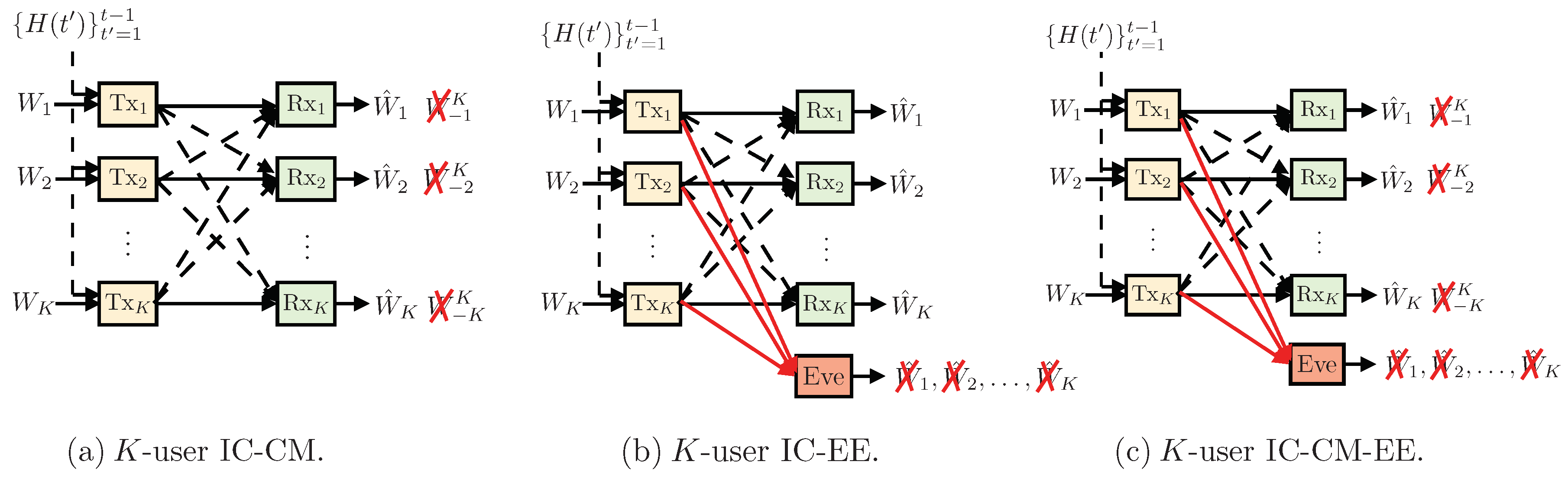
In this work, we consider the K-user SISO interference channel with secrecy constraints and delayed CSIT. More specifically, we study three channel models (see Figure 1), namely: (1) K-user interference channel with confidential messages, (2) K-user interference channel with an external eavesdropper, and (3) K-user interference channel with confidential messages and an external eavesdropper. We focus on answering the following fundamental questions regarding these channel models: (a) is positive SDoF achievable for the interference channel with delayed CSIT?, and (b) if yes, then how does the SDoF scale with K, the number of users?
Contributions: We answer the above questions for all the three channel models in the affirmative by showing that positive SDoF is indeed achievable for all these models, for a large number of users, K. We show that for the K-user interference channel with confidential messages (IC-CM), SDoF is achievable. Also, we show that for the K-user interference channel with an external eavesdropper (IC-EE), SDoF is achievable, and for the K-user with confidential messages and an external eavesdropper (IC-CM-EE), is achievable. In Table 1, we summarize the main results for the K-user IC under various secrecy constraints, and different CSIT assumptions (i.e., perfect CSIT, delayed CSIT and no CSIT).
These results highlight the fact that in presence of delayed CSIT, there is negligible DoF scaling loss due to the secrecy constraints in the network compared to the no secrecy case [8]. Our main contribution is a novel secure retrospective interference alignment scheme, that is specialized for the interference channel with delayed CSIT. Our transmission scheme is inspired by the work of [8] in terms of the organization of the transmission phases. One of the main differences is that the transmitters mix their information symbols with artificial noises so that the signals at each unintended receiver are completely immersed in the space spanned by artificial noise. However, this mixing must be done with only delayed CSIT, and it should also allow successful decoding at the respective receiver. Our scheme works over two phases: Phase one, in which each transmitter sends information symbols mixed with artificial noises, and repeats such transmission over multiple rounds. Subsequently, in the next phase, each transmitter carefully sends a function of the net interference and artificial noises (generated in previous phase), which is simultaneously useful to all receivers. The equivocation analysis of the proposed scheme is non-trivial due to the repetition and retransmission strategies employed by the transmitters.
Organization of the paper: The rest of the paper is organized as follows. Section 2 describes the system models. The main results and discussions are presented in Section 3. Section 4 provides the achievable scheme under delayed CSIT and confidential messages. Section 5 and Section 6 discuss two other secrecy constraints: (1) K-user interference channel with an external eavesdropper (IC-EE), and (2) K-user interference channel with confidential messages and an external eavesdropper (IC-CM-EE), respectively. We conclude the paper and discuss the future directions in Section 7. Finally, the detailed proofs are deferred to the Appendices.
Notations: Boldface uppercase letters denote matrices (e.g., ), boldface lowercase letters are used for vectors (e.g., ), we denote scalars by non-boldface lowercase letters (e.g., x), and sets by capital calligraphic letters (e.g., ). The set of natural numbers, integer numbers, real numbers, and complex numbers are denoted by , , , and , respectively. For a general matrix with dimensions of , , and denote the transpose and Hermitian transpose of , respectively. We denote the partitioned matrix of two matrices and as . We denote the identity matrix of the order M with . Let denote the differential entropy of a random vector , and denote the mutual information between two random vectors and . We denote a complex-Gaussian distribution with a mean and a variance by . For rounding operations on a variable x, we use as the floor rounding operator on x and as the ceiling rounding operator on x.
2. System Model
We consider the K-user interference channel with secrecy constraints and delayed CSIT (shown in Figure 1). The input–output relationship at time slot t is
where is the signal received at receiver k at time t, is the channel coefficient at time t between transmitter j and receiver k, and is the transmitted signal from transmitter k at time t with an average power constraint . The additive noise at receiver k is independent and identically distributed (i.i.d.) across users and time. is the received signal at the eavesdropper at time t, is the channel coefficient at time t between transmitter j and the external eavesdropper, and is the additive noise at the eavesdropper. The channel coefficients are assumed to be i.i.d. across time and users. We assume perfect CSI at all the receivers. We further assume that the CSIT is delayed, i.e., CSI is available at each transmitter after one time slot without error. Also, we assume that the external eavesdropper’s CSI is not available at the transmitters (i.e., no eavesdropper CSIT).
Let denote the rate of message intended for receiver k, where is the cardinality of the kth message. A code is described by the set of encoding and decoding functions as follows: the set of encoders at the transmitters are given as: where the message is uniformly distributed over the set , and is the set of all channel gains at time . The transmitted signal from transmitter k at time slot t is given as: . The decoding function at receiver k is given by the following mapping: , and the estimate of the message at receiver k is defined as: . The rate tuple is achievable if there exists a sequence of codes which satisfy the decodability constraints at the receivers, i.e.,
and the corresponding secrecy requirement is satisfied. We consider three different secrecy requirements:
- IC-CM, Figure 1a, all unintended messages are kept secure against each receiver, i.e.,where as , , and is the set of all channel gains (i.e., legitimate receivers and external eavesdropper) over the channel uses.
- IC-EE, Figure 1b, all of the messages are kept secure against the external eavesdropper, i.e.,
The supremum of the achievable sum rate, , is defined as the secrecy sum capacity . The optimal sum secure degrees of freedom () is then defined as follows:
represents the optimal scaling of the secrecy capacity with , where P is the transmitted power, i.e., it is the pre-log factor of the secrecy capacity at high SNR.
In the next Section, we present our main results on the achievable sum SDoF with the three different secrecy constraints and delayed CSIT.
3. Main Results
Theorem 1.
For the K-user IC-CM with delayed CSIT, the following secure sum degrees of freedom is achievable:
where,
We next simplify the above expression and present a lower bound on the achievable SDoF. Using this lower bound, we observe that the achievable SDoF scales with , where K is the number of users.
Corollary 1.
For the K-user IC-CM with delayed CSIT, the achievable SDoF in Equation (7) is lower bounded as
where .
We present the proof of Theorem 1 and Corollary 1 in Section 4.
Theorem 2.
For the K-user IC-EE with delayed CSIT, the following secure sum degrees of freedom is achievable:
where,
We next simplify the above expression and present a lower bound on the .
Corollary 2.
For the K-user IC-EE with delayed CSIT, the achievable SDoF in Equation (7) is lower bounded as
We present the proof of Theorem 2 and Corollary 2 in Section 5.
Theorem 3.
For the K-user IC-CM-EE with delayed CSIT, the following secure sum degrees of freedom is achievable:
where,
In the next Corollary, we simplify the above expression and present a lower bound on the .
Corollary 3.
For the K-user IC-CM-EE with delayed CSIT, the achievable SDoF in Equation (7) is lower bounded as
We present the proof of Theorem 3 and Corollary 3 in Section 6.
Remark 1.
We next compare the secure sum DoF of the previous Theorems to that of [8] (i.e., without secrecy constraints). For the K-user interference channel without secrecy constraints, the achievable sum DoF in [8] is given as:
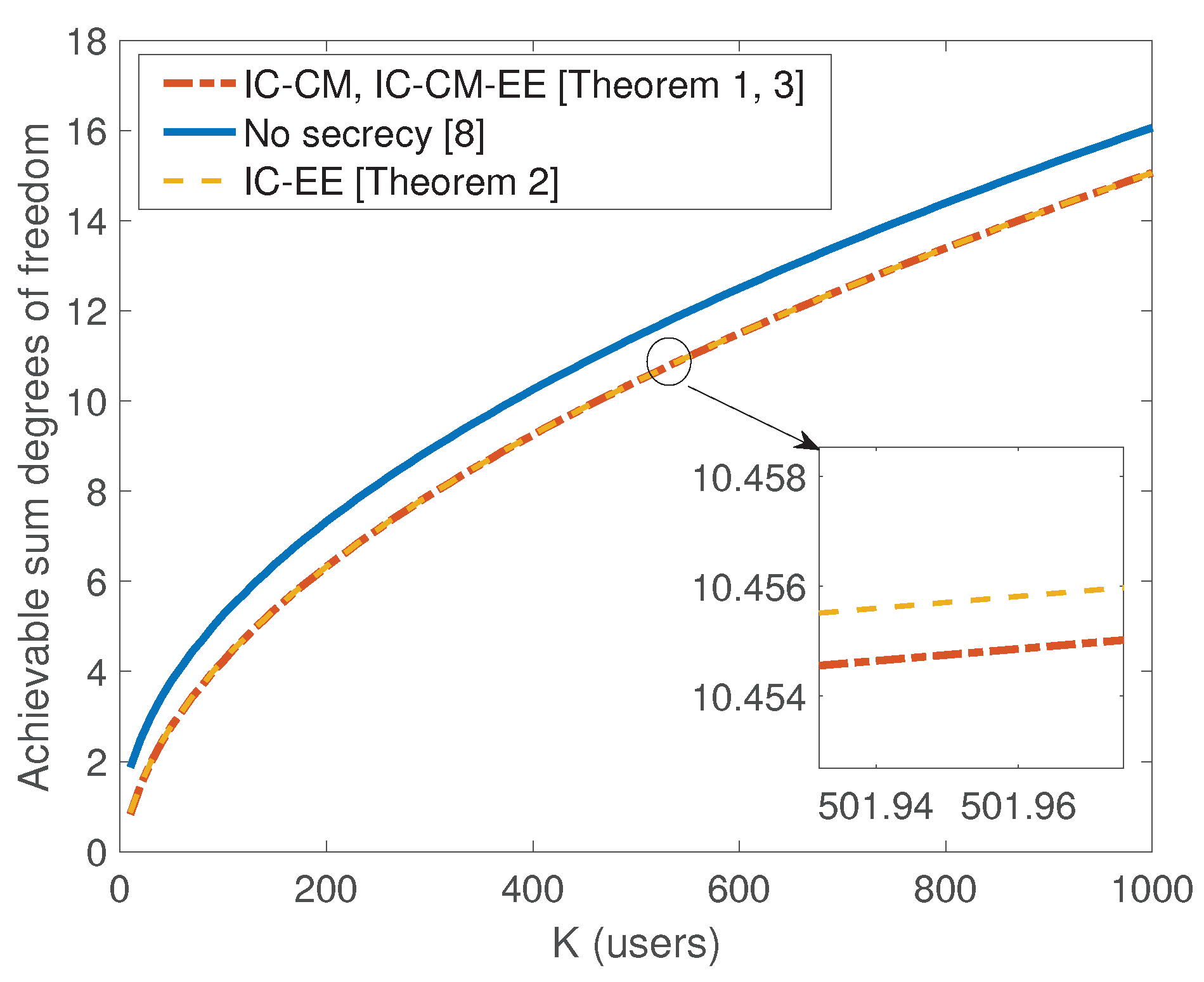
where (a) follows from the fact that . Comparing these results together, we can conclude that the scaling behavior of the sum SDoF is still attainable and there is negligible scaling loss in sum SDoF compared to no secrecy case for sufficiently large K (see Figure 2). Also, we present numerical evaluations for the sum SDoF in Table 2.
4. Proof of Theorem 1
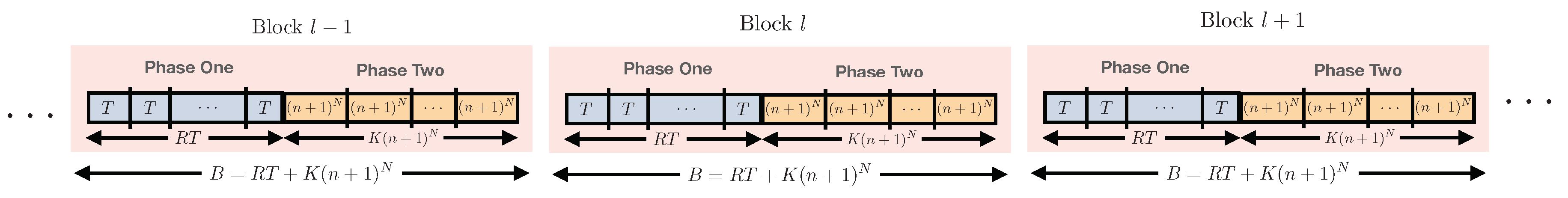
In this Section, we present the proof of Theorem 1. The transmission scheme consists of transmission blocks, where each block is of duration B. Across blocks, we employ stochastic wiretap coding (similar to the techniques employed in the literature on compound wiretap channels, see [19,23,24]). Within each block, the transmission is divided into two phases, which leverages delayed CSIT. In order to analyze the rate of the proposed scheme, we first take the limit of number of blocks , followed by the limit . For a given block, if we denote the (B-length) input of transmitter i as , and output of receiver i as , then the secure rate achievable by stochastic wiretap coding is given by:
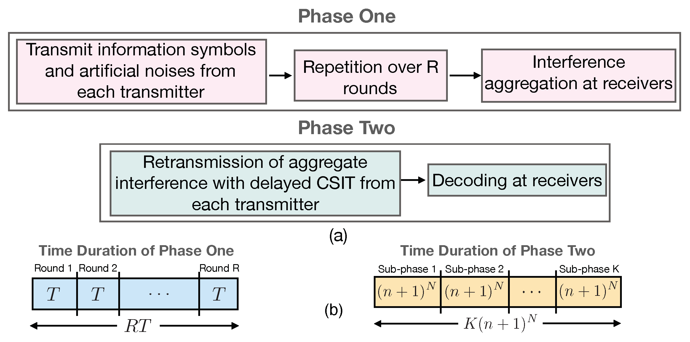
where is the vector of information symbols sent by transmitter i. Figure 3 gives an overview for these steps: stochastic encoding over blocks, and the two-phase scheme within each block that leverages delayed CSIT.
4.1. Overview of the Achievability Scheme and SDoF Analysis
In this subsection, we present our secure transmission scheme. We consider a transmission block of length , where R denotes the number of transmission rounds and , and n is an integer. The transmission scheme works over two phases. The goal of each transmitter is to securely send information symbols to its corresponding receiver. In the first phase, each transmitter sends random linear combinations of the information symbols and the artificial noise symbols in T time slots. Each transmitter repeats such transmission for R rounds, and hence, phase one spans time slots.
By the end of phase one, each receiver applies local interference alignment on its received signal to reduce the dimension of the aggregate interference. In the second phase, each transmitter knows the channel coefficients of phase one due to delayed CSIT. Subsequently, each transmitter sends a function of the net interference and artificial noises (generated in previous phase) which is simultaneously useful to all receivers. More specifically, each transmitter seperately sends linear equations of the past interference to all receivers. Therefore, phase 2 spans time slots.
By the end of both phases, each receiver is able to decode its desired information symbols while satisfying the confidentiality constraints. The main aspect is that the parameters of the scheme (i.e., number of artificial noise symbols, number of repetition rounds, and durations of the phases) must be carefully selected to allow for reliable decoding of legitimate symbols, while satisfying the confidentiality constraints.
Therefore, the transmission scheme spans time slots, this scheme leads to the following achievable SDoF:
We calculate the achievable sum SDoF of this scheme in full detail in Section 4.3. Before we present the details of the scheme, we first optimize the achievable SDoF in Equation (20) with respect to the number of rounds R and also simplify the above expression, which leads to the expression in Corollary 1.
Lemma 1.
The optimal value of which maximizes Equation (20) is given by
Now, in order simplify the obtained expression in Equation (20), we state the following Corollary.
Corollary 4.
The optimal value of number of rounds is lower bounded by
We present the proof of Lemma 1 and Corollary 4 in Appendix A.
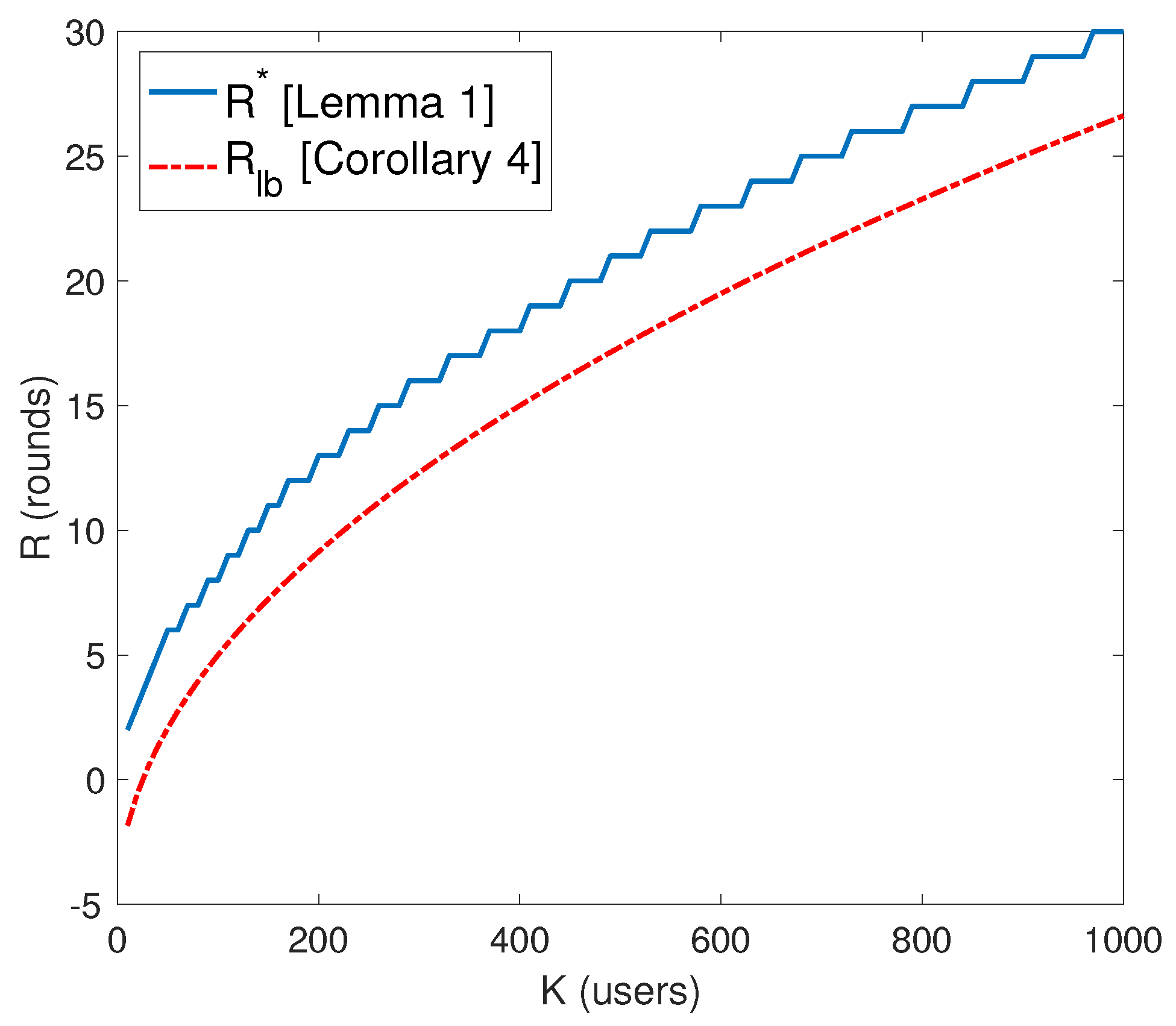
Figure 4 depicts a comparison of between the two values of R (i.e., optimal and lower bound ). By substituting in Equation (20) leads to a lower bound on as follows:
where in (a), the term in the denominator is negative, , so neglecting this term gives us Equation (26). In step (b), since the term is positive, , hence omitting this term gives Equation (28). To this end, we get Equation (28) which shows the scaling of the achievable SDoF with K, the number of users.
4.2. Detailed Description of the Achievability Scheme
Figure 5 depicts an overview of the two transmission phases. We now present the transmission scheme in full detail. For our scheme, we collectively denote the L symbols transmitted over L time slots as a super symbol and call this as the L symbol extension of the channel. With the extended channel, the signal vector at the kth receiver can be expressed as
where is a column vector representing the L symbols transmitted by transmitter k in L time slots. is a diagonal matrix representing the L symbol extension of the channel as follows:
where is the channel coefficient between transmitter j and receiver k at time slot t. Now we proceed to the proposed scheme which works over two phases.
4.2.1. Phase 1: Interference Creation with Information Symbols and Artificial Noises
Recall that the goal of each transmitter is to send information symbols securely to its respective receiver. This phase is comprised of R rounds, where, in each round, every transmitter j sends linear combinations of the information symbols , mixed with artificial noises , where the elements of are drawn from complex-Gaussian distribution with average power P. Hence, the signal sent by transmitter j in each round r can be written as
where is a random mixing matrix of dimension whose elements are drawn from complex-Gaussian distribution with zero mean and unit variance at transmitter j. is known at all terminals (all transmitters and receivers). The received signal at receiver k for round is given by
where is the column vector representing the T symbol extension of the transmitted symbols from transmitter j, and represents the receiver noise in round r at receiver k. This phase spans time slots where is the number of transmission rounds and time slots where and .
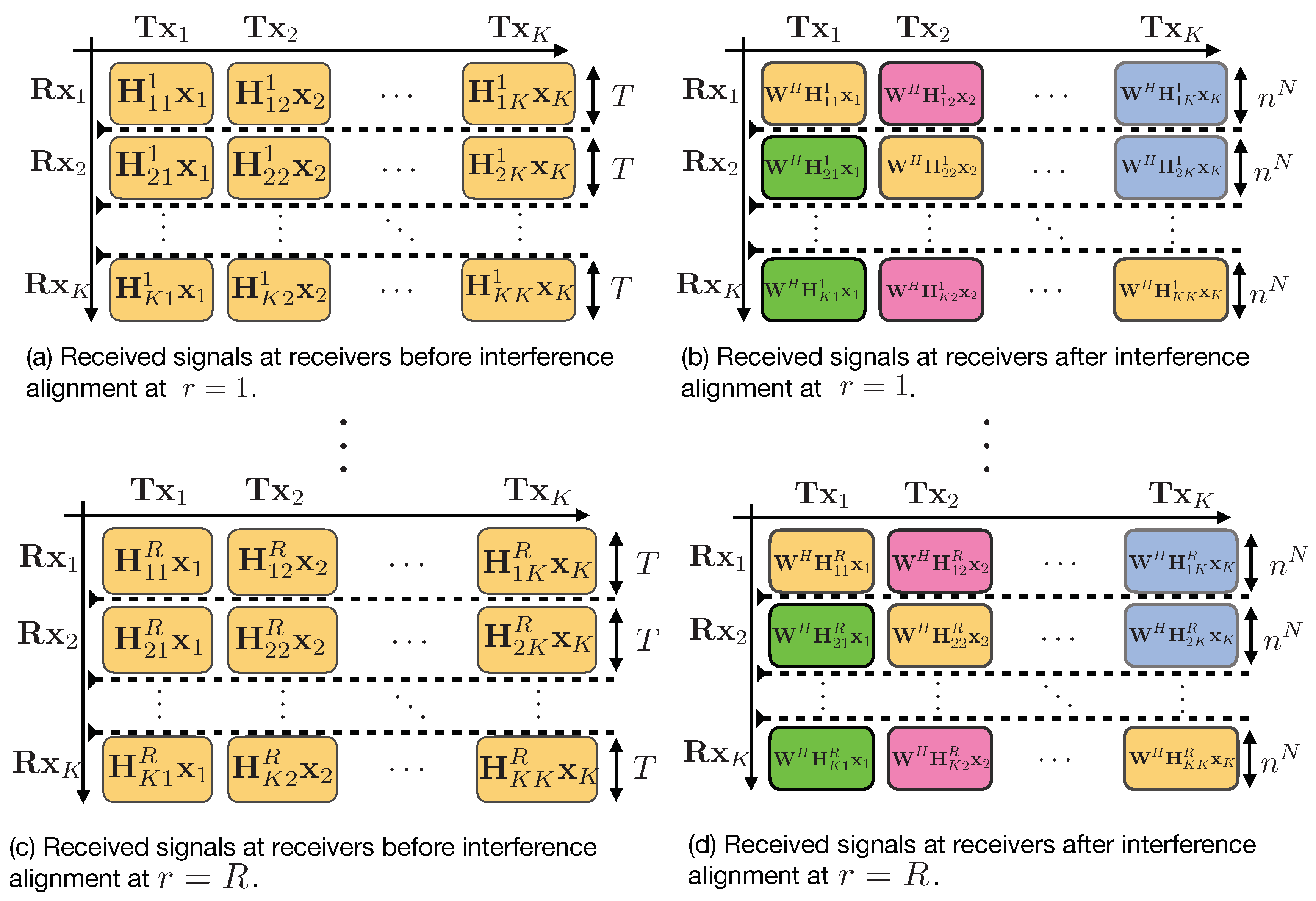
⋄ Interference Aggregation at Receivers
At the end of phase 1, each receiver k has the signals , over R rounds. Each receiver performs a linear post-processing of its received signals in order to align the aggregate interference (generated from symbols and artificial noises) from the unintended transmitters. In particular, each receiver multiplies its received signals in the rth block with a matrix (of dimension ) as follows:
The goal is to design the matrices and such that
where . Here the notation means that the set of row vectors of matrix is a subset of the row vectors of matrix . To this end, we choose and as follows:
where is the all ones column vector and the set . Note that the set does not contain the channel matrix that carries the information symbols intended to receiver k. However, multiplying with any channel gain that appears in results in aligning this signal within asymptotically. It is worth noting that, defines all the possible interference generated by the transmitters at all receivers. Hence, this choice of and guarantees that the alignment condition Equation (36) is satisfied. Therefore, the received signal after post-processing in round r at receiver k can be written as
where is a selection and permutation matrix. Now after the end of phase 1, receiver k has equations of T desired symbols (which are composed of information symbols and artificial noises generated by the transmitter k) plus interference terms, which are of dimension . Figure 6 gives a detailed structure for the first phase of the transmission scheme.
4.2.2. Phase 2: Re-Transmission of Aggregate Interference with Delayed CSIT
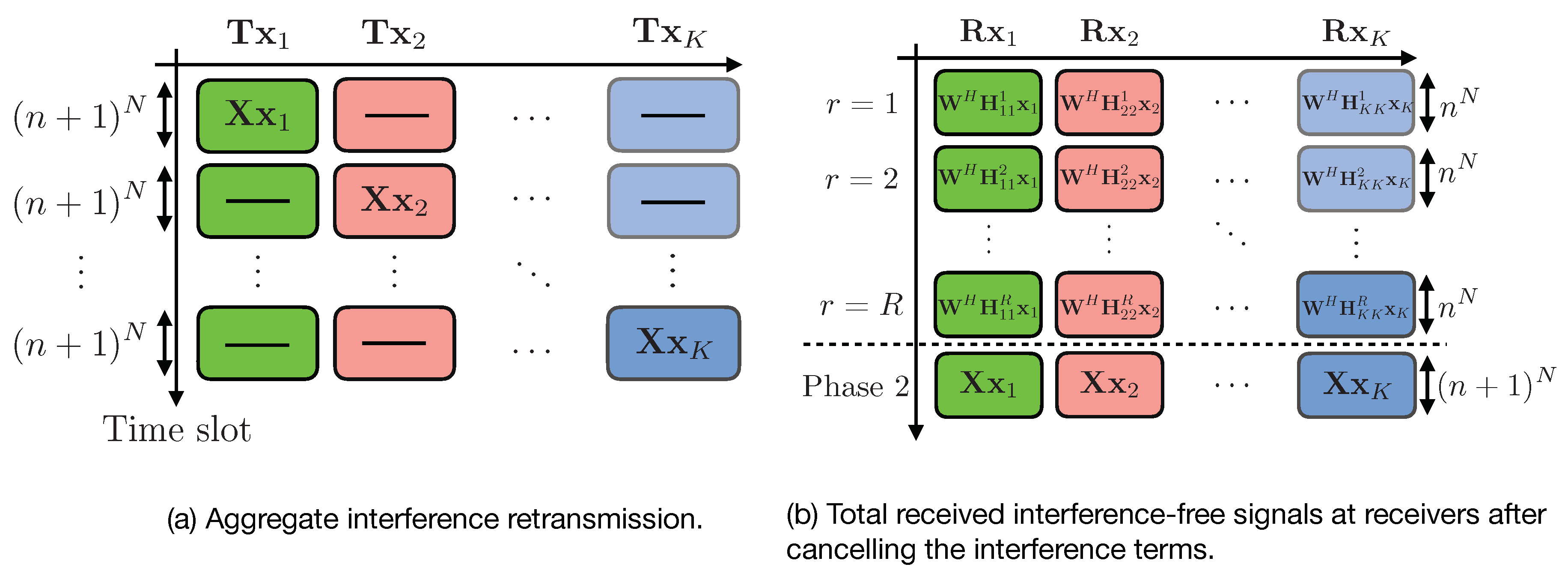
For the second phase, each transmitter k uses time slots to re-transmit the aggregated interference generated in the first phase at the receivers, which is sufficient to cancel out the interference term at receiver , and to provide additional equations of the desired symbols to receiver k. Then, this phase spans time slots. The transmitted signal from transmitter k is as follows:
⋄ Decoding at Receivers
At the end of phase 2, the interference at receiver k is removed by subtracting the terms from the equalized signal , i.e., (ignoring the additive noise )
Canceling the interference terms leaves each receiver with useful linear equations besides useful equations from transmitter k (from phase 2). At the end of phase 2, receiver k will collectively get the following signal,
Therefore, at the end of phase 2, each receiver has enough linear equations of the desired symbols. In order to ensure decodability, we need to prove that is full rank and hence each receiver will be able to decode its desired information symbols. First, we notice that is full rank matrix and hence [25]. In Appendix B, we show that is full rank. Figure 7 gives a detailed structure for the second phase of the transmission scheme.
Before we start the achievable secure rate analysis, we want to highlight first on the dimensions of the information symbols and the artificial noises , .
4.2.3. Choice of and to Satisfy the Confidentiality Constraints
Without loss of generality, let us consider receiver 1. After decoding and , receiver 1 will have equations of , from phase one, and equations of , from phase two. Then, the total number of equations seen at receiver 1 is . Hence, in order to keep the unintended information symbols of transmitters at this receiver secure, we require that the number of these equations must be at most equal to the total number of the artificial noise dimensions of the transmitters, i.e.,
Therefore, we choose as
Note that since , so we can get as follows:
We next compute the achievable secrecy rates and SDoF for the K-user interference channel with confidential messages and delayed CSIT.
4.3. Secrecy Rate and SDoF Calculation
Using stochastic encoding described in Appendix XII of [26], for a block length , the following secure rate is achievable:
where is the mutual information between the information symbols vector and , the received composite signal vector at the intended receiver i, given the knowledge of the channel coefficients. is the mutual information between and , the received composite signal vector at the unintended receiver j, i.e., the strongest adversary with respect to transmitter i, conditioned on the information symbols . In terms of differential entropy, we can write,
We collectively write the received signal at receiver i over time slots as follows:
where,
![Entropy 21 01092 i002]() where has dimensions of . Note that is partitioned into two sub matrices and . consists of block matrices, where each block matrix has dimensions of whose elements are i.i.d. drawn from a continuous distribution and hence, it is full rank, almost surely (i.e., ). has a block diagonal structure (each block matrix has dimensions of ) since the transmission in phase two of the scheme is done in TDMA fashion. Note that each block is a full rank matrix (i.e., ). The matrix is a full rank matrix as proved in [26]. The matrix can be written as follows:
where is the block diagonal matrix with dimensions of . Furthermore, we write
as a column vector of length , which contains the information symbols and the artificial noises of transmitters .
where has dimensions of . Note that is partitioned into two sub matrices and . consists of block matrices, where each block matrix has dimensions of whose elements are i.i.d. drawn from a continuous distribution and hence, it is full rank, almost surely (i.e., ). has a block diagonal structure (each block matrix has dimensions of ) since the transmission in phase two of the scheme is done in TDMA fashion. Note that each block is a full rank matrix (i.e., ). The matrix is a full rank matrix as proved in [26]. The matrix can be written as follows:
where is the block diagonal matrix with dimensions of . Furthermore, we write
as a column vector of length , which contains the information symbols and the artificial noises of transmitters .

Before we proceed, we present two Lemmas; we provide the proof of Lemma 2 in Appendix C. For Lemma 3, we follow similar steps as in [17], the proof of this Lemma is provided in [26].
Lemma 2.
Let be a matrix with dimension and be a zero-mean jointly complex Gaussian random vector with covariance matrix . Also, let be a zero-mean jointly complex Gaussian random vector with covariance matrix , independent of , then
where are the singular values of .
Lemma 3.
Consider two matrices and where . The elements of matrix are chosen independently from the entries of at random from a continuous distribution. Then,
Without loss of generality, let us consider the first transmitter. The received signal at the first receiver after removing the interference terms is written as follows:
⋄ Lower Bounding Term A
We note that forms a Markov chain, thus
Using Equation (56), we can write as follows:
where are the singular values of . In (a), we note that is full rank. Using full rank decomposition Theorem [25], we conclude that is also full rank, i.e., .
Now, we write as follows:
where,
where has dimensions of , and are the singular values of . has dimensions of . Note that, we can view the mixing matrix being composed of two parts i.e., where corresponding to the information symbol and corresponding to the artificial noise .
From the substitution of Equations (62) and (66) into Equation (58), we obtain
Before calculating the second term, i.e., Term B. We collectively write the received signal at receiver j over time slots as follows:
where is written as follows:
![Entropy 21 01092 i003]() where has dimensions of . The matrix V is written as follows:
where is the block diagonal matrix with dimensions of . Furthermore, we write
as a column vector of length , which contains the information symbols and the artificial noises of transmitters .
where has dimensions of . The matrix V is written as follows:
where is the block diagonal matrix with dimensions of . Furthermore, we write
as a column vector of length , which contains the information symbols and the artificial noises of transmitters .

⋄ Upper Bounding Term B
Now, we can compute Term B, i.e., as follows:
where is a truncated version of with dimensions . Furthermore, we write
as a column vector of length , which contains information symbols and artificial noises of transmitters. Also, is a truncated version of with dimensions . Furthermore, we write
as a column vector of length , which contains only artificial noises of transmitters.
In (a), we used Lemma 2. are the singular values of . Note that in (b), is an invertible matrix with rank , therefore .
Now, we write as follows:
where are the singular values of . In (a), is a truncated version of with dimensions of , therefore, . In (b), we used Lemma 3, i.e., . The multiplication of and can be viewed as linear combinations of the rows of matrix , whose elements are generated independently of from a continuous distribution. In Appendix XI of [26], we show that multiplying with a non-square random matrix does not reduce the rank of matrix , almost surely. Hence, from the above argument, in order to ensure that , we must pick , which gives the reasoning behind the choice of the parameter .
From the substitution of Equations (81) and (84) into Equation (75), we obtain
Combining Equations (69) and (85), we have
where , , and .
We now simplify the two terms as follows:
where in (a), we used the property that . Also,
Combining Equations (90) and (94) in Equation (87) and taking the limit , we get the following:
Dividing by and letting , we get
Therefore, the achievable secure sum degrees of freedom is obtained as
Hence, this completes the proof of Theorem 1.
5. Proof of Theorem 2
We follow a similar achievability scheme presented in Section 4, however, the main differences are the number of information symbols, the artificial noises used for transmission and the number of rounds in the first phase of the scheme. The goal of each transmitter is to securely send information symbols to its corresponding receiver and keeping all messages secure against the external eavesdropper.
The total number of equations seen at the eavesdropper is of , . Hence, in order to keep the unintended information symbols of K transmitters at this receiver secure, we require that the number of these equations must be at most equal to the total number of the artificial noise dimensions of the K transmitters, i.e.,
Therefore, we choose as
Since , so we can get as follows:
To this end, this scheme leads to the following achievable SDoF:
Since the achieved SDoF in Equation (101) is a concave function of R. Hence, getting the optimal is obtained by equating the first derivative of the function with zero. Therefore, the optimal is
Now we approximate the obtained SDoF as follows:
where in (a), the term in the denominator is negative, , so neglecting this term gives us Equation (106). In step (b), since the term is positive, hence omitting this term gives Equation (108).
Secrecy Rate and SDoF Calculation
For a transmission of block length , the achievable secure rate is defined as
where is the mutual information between the information symbols vector and , the received composite signal vector at the intended receiver i, given the knowledge of the channel coefficients. is the mutual information between and , the received composite signal vector at the external eavesdropper, conditioned on the information symbols . Note that is collectively written as
where,
![Entropy 21 01092 i004]() where has dimensions of . Each is a matrix represents the channel gains between each transmitter and the external eavesdropper.
where has dimensions of . Each is a matrix represents the channel gains between each transmitter and the external eavesdropper.

The analysis of the achievable secure rate and SDoF follows similar steps as those in Section 4.3. This completes the proof of Theorem 2.
6. Proof of Theorem 3
We follow the same transmission scheme presented in Section 4. The goal of each transmitter is to securely send information symbols to its corresponding receiver and keeping all messages secure against the external eavesdropper and the unintended receivers.
We have two secrecy constraints must be satisfied, i.e.,
Equation (113) can be re-written as
So if we pick as
we need to check that . can be written as
where in (a), the first two terms are positive, hence, is strictly greater than . To this end, we conclude that the two secrecy constraints are satisfied. Hence, we achieve the same SDoF of Theorem 1, i.e.,
Secrecy Rate and SDoF Calculation
For a transmission of block length , the achievable secure rate is defined as
The analysis of the achievable secure rate and SDoF follows similar steps as those in Section 4.3. This completes the proof of Theorem 3.
7. Conclusions
In this paper, we studied the K-user interference channel with three secrecy constrained channel models and delayed CSIT: We showed that for the K-user interference channel with confidential messages, the sum secure degrees of freedom (SDoF) is at least , and scales with square root of the number of users. Also, we showed that for the K-user interference channel with an external eavesdropper, SDoF is achievable. For the K-user interference channel with confidential messages and an external eavesdropper, we showed that is achievable. To achieve these results, we have proposed novel secure retrospective interference alignment schemes which satisfy both secrecy and decodability at receivers. To the best of our knowledge, this is the first result showing scaling of SDoF for the interference channel with secrecy constraints and delayed CSIT. An interesting open problem is to investigate the optimality of these schemes, and finding upper bounds on SDoF with delayed CSIT for these channel models.
Author Contributions
Conceptualization, M.S., R.T. and M.L.; Formal analysis, M.S., R.T. and M.L.; Investigation, M.S., R.T. and M.L.; Methodology, M.S., R.T. and M.L.; Validation, M.S., R.T. and M.L.; Visualization, M.S., R.T. and M.L.; Writing—original draft, M.S., R.T. and M.L.; Writing—review and editing, M.S., R.T. and M.L.
Funding
This work of M.S., R.T., and M.L. was supported in part by U.S. NSF through grants CCF-1559758 and CNS-1715947, CNS-1564477, and ONR YIP grant N00014-16-1-2650, and was presented in part at ISIT conference, Colorado, USA, June 2018.
Conflicts of Interest
The authors declare no conflict of interest.
Appendix A. (Proof of Lemma 1 and Corollary 4)
For , the function strictly increases and for the function strictly decreases, where is given by
Alternatively,
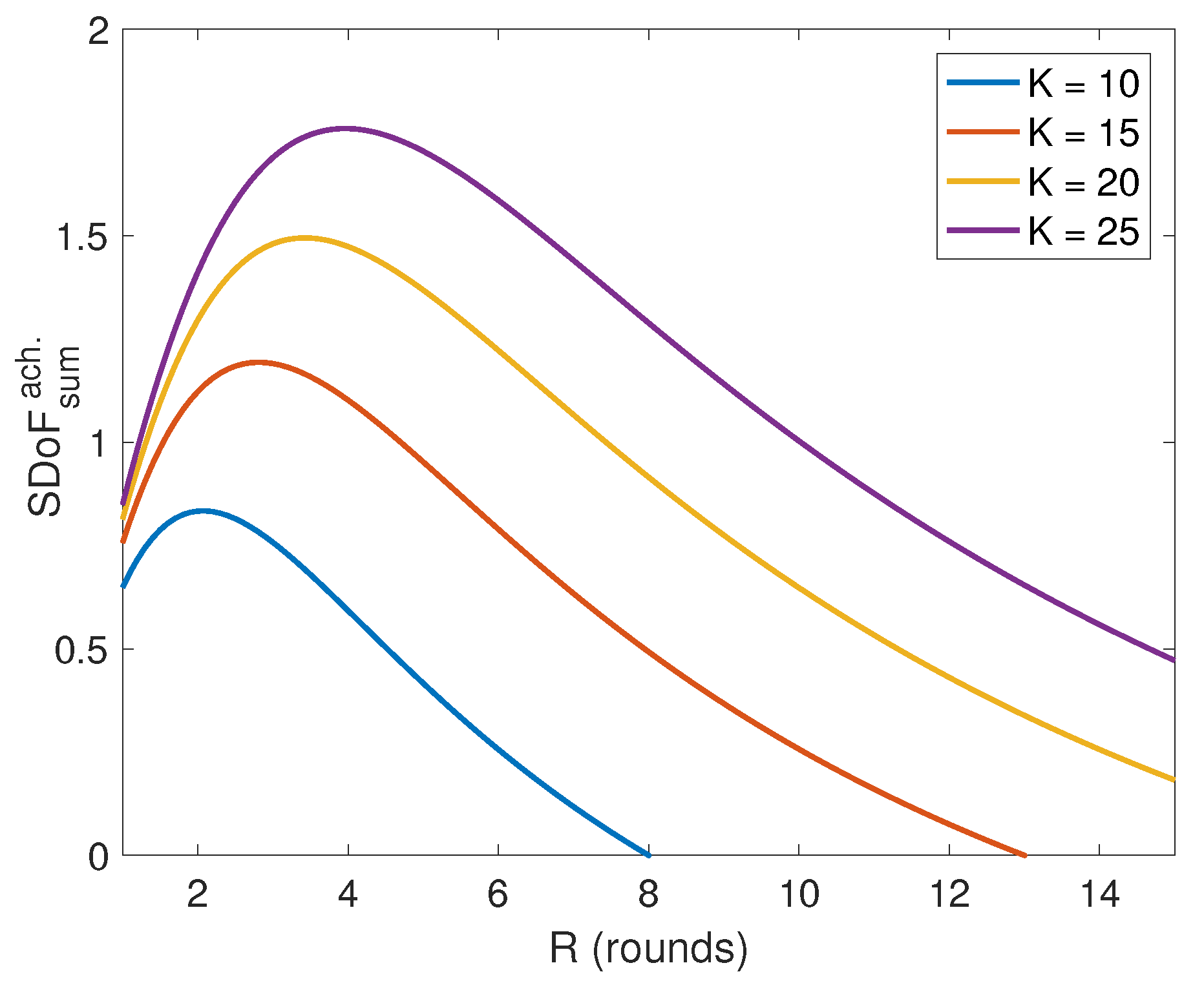
Figure A1 shows the behavior of the achievable sum SDoF as a function of the number of rounds R. The optimal value of R can be obtained by equating the first derivative of to zero as follows:
Figure A1.
Plot for the achievable sum SDoF as a function of the number of rounds R for different number of user K.
Figure A1.
Plot for the achievable sum SDoF as a function of the number of rounds R for different number of user K.

After differentiating Equation (A6), we will get the following:
The solution of the previous equation is
where in (a), since , we apply the floor rounding operator on the obtained value of R. In (b), we used the property of the floor operator, i.e., . In (c), the term is greater than .
Appendix B. (Proof of Linear Independence in Equation (43))
In this Appendix, we show that by the end of the transmission scheme, each receiver gets linear independent equations of the desired signals (i.e., the information symbols and the artificial noises). Then, we need to show that the following matrix
is full rank. Since is a square matrix, then it is sufficient to show that . Without loss of generality, we consider receiver 1 which has the following matrix
Since , we will instead show that , which is given as follows:
Note that and are function of the diagonal entries of the channels and . More specifically, the entries of are . depends on plus whose elements are and, . For notation convenience, let us denote these channel coefficients as and . The elements of are written as a monomial function of the random variables and as follows:
where is the exponent of the random variable . Note that for two different columns and , . More specifically, the structure of is as follows:
and for as
where and . The full matrix is written as follows:
The determinant of matrix can be written as follows:
where is the cofactor matrix corresponding after removing the 1st row and the jth column with coefficient . Now we will show that is full rank by contradiction. The zero determinant assumption implies one of the following two events:
- takes a value equal to one of the roots of the polynomial equation.
- All the cofactors of the polynomials are zero.
For the first event, none of the cofactors depends on the random variables . Note that are drawn from a continuous distribution, then the probability of these random variables that take finitely many values as a solution for the polynomial is zero almost surely. Therefore, the second event happens with probability greater than zero, which implies
Then with probability higher than zero. implies that the determinant of the matrix obtained by stripping off the first row and last column of is equal to zero with non-zero probability. Repeating the process of stripping off each row and column, it will end up with matrix with value one which contradicts the assumption that . It is worth noting that stripping off the rows and columns procedure preserves the structure of the matrix which means that the cofactors do not depend on the coefficients. To conclude, the determinant of does not equal zero almost surely, which implies that the desired symbols are decoded successfully at the receiver side with probability one.
Appendix C. (Proof of Lemma 2)
Note that is a jointly complex Gaussian vector with zero mean and covariance . From [27], is written as
It is worth noting that is positive semi-definite, with eigenvalue decomposition , where is a diagonal matrix with r non-zero eigenvalues where . Then,
Next, we use the Sylvester’s identity for determinants, i.e., . Using this identity, we have
Since is a unitary matrix, (i.e., ), we have the following:
This completes the proof of Lemma 2.
References
- Maddah-Ali, M.A.; Tse, D. Completely stale transmitter channel state information is still very useful. IEEE Trans. Inf. Theory 2012, 58, 4418–4431. [Google Scholar]
- Cadambe, V.R.; Jafar, S.A. Interference alignment and degrees of freedom of the K-user interference channel. IEEE Trans. Inf. Theory 2008, 54, 3425–3441. [Google Scholar] [CrossRef]
- Ghasemi, A.; Motahari, A.S.; Khandani, A.K. On the degrees of freedom of X channel with delayed CSIT. In Proceedings of the IEEE International Symposium on Information Theory (ISIT), St. Petersburg, Russia, 31 July–5 August 2011; pp. 767–770. [Google Scholar]
- Maggi, L.; Cottatellucci, L. Retrospective interference alignment for interference channels with delayed feedback. In Proceedings of the IEEE Wireless Communications and Networking Conference (WCNC), Shanghai, China, 1–4 April 2012; pp. 453–458. [Google Scholar]
- Abdoli, M.J.; Ghasemi, A.; Khandani, A.K. On the degrees of freedom of K-user SISO interference and X channels with delayed CSIT. IEEE Trans. Inf. Theory 2013, 59, 6542–6561. [Google Scholar] [CrossRef]
- Kang, M.G.; Choi, W. Ergodic interference alignment with delayed feedback. IEEE Signal Process. Lett. 2013, 20, 511–514. [Google Scholar] [CrossRef]
- Maleki, H.; Jafar, S.A.; Shamai, S. Retrospective interference alignment over interference networks. IEEE J. Sel. Top. Signal Process. 2012, 6, 228–240. [Google Scholar] [CrossRef]
- Castanheira, D.; Silva, A.; Gameiro, A. Retrospective Interference Alignment: Degrees of Freedom Scaling With Distributed Transmitters. IEEE Trans. Inf. Theory 2017, 63, 1721–1730. [Google Scholar] [CrossRef]
- Yener, A.; Ulukus, S. Wireless physical-layer security: Lessons learned from information theory. Proc. IEEE 2015, 103, 1814–1825. [Google Scholar] [CrossRef]
- Mukherjee, P.; Tandon, R.; Ulukus, S. Physical Layer Security with Delayed, Hybrid and Alternating Channel State Knowledge, Information Theoretic Security and Privacy of Information Sources; Cambridge University Press: Cambridge, UK, 2017. [Google Scholar]
- Liang, Y.; Poor, H.V.; Shamai, S. Information theoretic security. Found. Trends® Commun. Inf. Theory 2009, 5, 355–580. [Google Scholar] [CrossRef]
- He, X.; Yener, A. K-user interference channels: Achievable secrecy rate and degrees of freedom. In Proceedings of the IEEE Information Theory Workshop (ITW) on Networking and Information Theory, Volos, Greece, 10–12 June 2009; pp. 336–340. [Google Scholar]
- Koyluoglu, O.O.; El Gamal, H.; Lai, L.; Poor, H.V. Interference alignment for secrecy. IEEE Trans. Inf. Theory 2011, 57, 3323–3332. [Google Scholar] [CrossRef]
- Xie, J.; Ulukus, S. Real interference alignment for the K-user Gaussian interference compound wiretap channel. In Proceedings of the 48th Annual Allerton Conference on Communication, Control, and Computing, Allerton, IL, USA, 29 September–1 October 2010; pp. 1252–1257. [Google Scholar]
- Bassily, R.; Ulukus, S. Ergodic secret alignment. IEEE Trans. Inf. Theory 2012, 58, 1594–1611. [Google Scholar] [CrossRef]
- Gou, T.; Jafar, S.A. On the secure degrees of freedom of wireless X networks. In Proceedings of the 46th Annual Allerton Conference on Communication, Control, and Computing, Urbana-Champaign, IL, USA, 23–26 September 2008; pp. 826–833. [Google Scholar]
- Nafea, M.; Yener, A. How many antennas does a cooperative jammer need for achieving the degrees of freedom of multiple antenna Gaussian channels in the presence of an eavesdropper? In Proceedings of the 51st Annual Allerton Conference on Communication, Control, and Computing, Monticello, IL, USA, 2–4 October 2013; pp. 774–780. [Google Scholar]
- Yang, S.; Kobayashi, M. Secure communication in K-user multi-antenna broadcast channel with state feedback. In Proceedings of the IEEE International Symposium on Information Theory (ISIT), Hong Kong, China, 14–19 June 2015; pp. 1976–1980. [Google Scholar]
- Xie, J.; Ulukus, S. Secure degrees of freedom of K-user Gaussian interference channels: A unified view. IEEE Trans. Inf. Theory 2015, 61, 2647–2661. [Google Scholar] [CrossRef]
- Xie, J.; Ulukus, S. Secure degrees of freedom of one-hop wireless networks. IEEE Trans. Inf. Theory 2014, 60, 3359–3378. [Google Scholar] [CrossRef]
- Mukherjee, P.; Ulukus, S. Secrecy in MIMO Networks with no eavesdropper CSIT. IEEE Trans. Commun. 2017, 65, 4382–4391. [Google Scholar] [CrossRef]
- Mukherjee, P.; Tandon, R.; Ulukus, S. Secure degrees of freedom region of the two-user MISO broadcast channel with alternating CSIT. IEEE Trans. Inf. Theory 2017, 63, 3823–3853. [Google Scholar] [CrossRef]
- Liang, Y.; Kramer, G.; Poor, H.V.; Shamai, S. Compound wiretap channels. EURASIP J. Wirel. Commun. Netw. 2009, 2009, 5. [Google Scholar] [CrossRef]
- Liu, R.; Maric, I.; Spasojevic, P.; Yates, R.D. Discrete memoryless interference and broadcast channels with confidential messages: Secrecy rate regions. IEEE Trans. Inf. Theory 2008, 54, 2493–2507. [Google Scholar] [CrossRef]
- Horn, R.A.; Johnson, C.R. Matrix Analysis; Cambridge University Press: Cambridge, UK, 2012. [Google Scholar]
- Seif, M.; Tandon, R.; Li, M. Secure Retrospective Interference Alignment. arXiv 2018, arXiv:1801.03494. [Google Scholar]
- Cover, T.M.; Thomas, J.A. Elements of Information Theory; John Wiley & Sons: Hoboken, NJ, USA, 2012. [Google Scholar]
Figure 1.
K-user interference channel (IC) with secrecy and delayed CSIT. The model in (a) has confidential message (CM) constraints, model in (b) assumes the presence of an external eavesdropper (EE), and the model in (c) has both confidentiality and secrecy constraints (CM and EE).
Figure 1.
K-user interference channel (IC) with secrecy and delayed CSIT. The model in (a) has confidential message (CM) constraints, model in (b) assumes the presence of an external eavesdropper (EE), and the model in (c) has both confidentiality and secrecy constraints (CM and EE).

Figure 2.
Comparison of achievable degrees of freedom (DoF) with delayed CSIT: with and without secrecy constraints.
Figure 2.
Comparison of achievable degrees of freedom (DoF) with delayed CSIT: with and without secrecy constraints.

Figure 3.
Stochastic encoding over transmission blocks for our proposed scheme.

Figure 4.
Comparison between the optimal value of R (number of rounds in phase one of the scheme) and its lower bound.
Figure 4.
Comparison between the optimal value of R (number of rounds in phase one of the scheme) and its lower bound.

Figure 5.
(a) Block diagram for the transmission scheme and (b) time duration of the phases.

Figure 6.
Graphical representation for the first phase of the proposed scheme.

Figure 7.
Graphical representation for the second phase of the proposed scheme.


Table 1.
Summary of results on the K-user interference channel with different secrecy constraints and channel state information at transmitters (CSIT) models. The highlighted results are from this paper. These results show that sum secure degrees of freedom (SDoF) scales with .
Table 1.
Summary of results on the K-user interference channel with different secrecy constraints and channel state information at transmitters (CSIT) models. The highlighted results are from this paper. These results show that sum secure degrees of freedom (SDoF) scales with .
 |
Table 2.
Numerical comparison between the sum SDoF with the sum DoF in [8].
© 2019 by the authors. Licensee MDPI, Basel, Switzerland. This article is an open access article distributed under the terms and conditions of the Creative Commons Attribution (CC BY) license (http://creativecommons.org/licenses/by/4.0/).
Share and Cite
MDPI and ACS Style
Seif, M.; Tandon, R.; Li, M. Secure Retrospective Interference Alignment. Entropy 2019, 21, 1092. https://0-doi-org.brum.beds.ac.uk/10.3390/e21111092
AMA Style
Seif M, Tandon R, Li M. Secure Retrospective Interference Alignment. Entropy. 2019; 21(11):1092. https://0-doi-org.brum.beds.ac.uk/10.3390/e21111092
Chicago/Turabian StyleSeif, Mohamed, Ravi Tandon, and Ming Li. 2019. "Secure Retrospective Interference Alignment" Entropy 21, no. 11: 1092. https://0-doi-org.brum.beds.ac.uk/10.3390/e21111092
Note that from the first issue of 2016, this journal uses article numbers instead of page numbers. See further details here.