Numerical Analysis on Natural Convection Heat Transfer in a Single Circular Fin-Tube Heat Exchanger (Part 1): Numerical Method


Abstract
:1. Introduction
2. Numerical Simulation
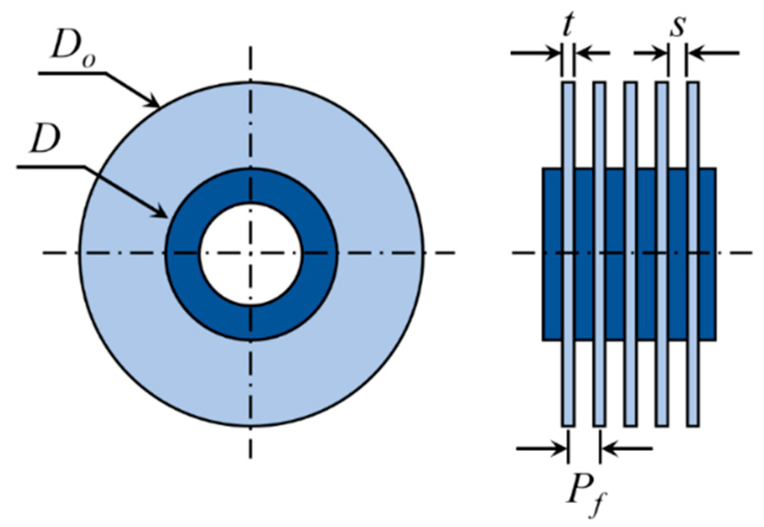
2.1. Equations Governing the Circular Fin-Tube Heat Exchanger
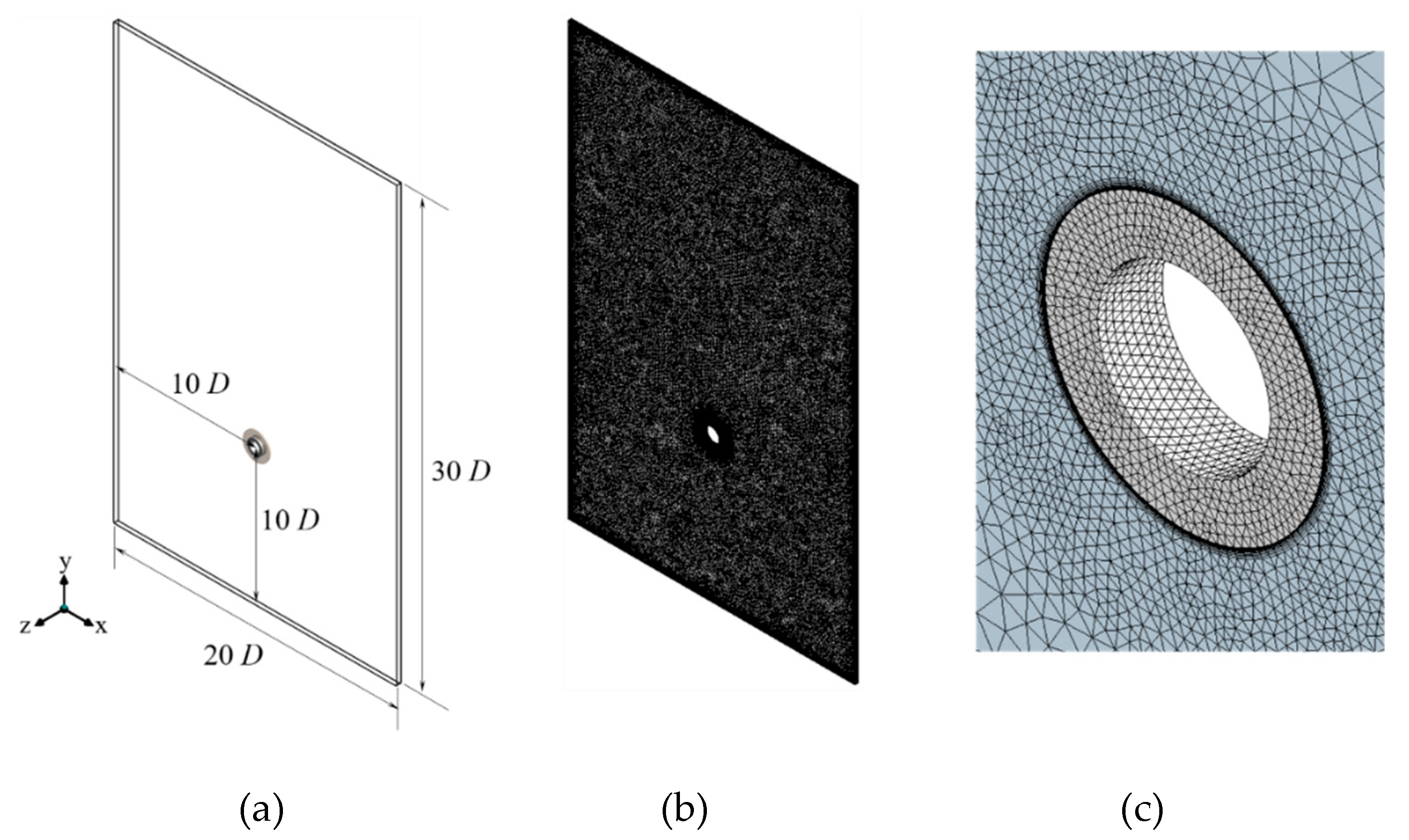
2.2. Numerical Simulation Method
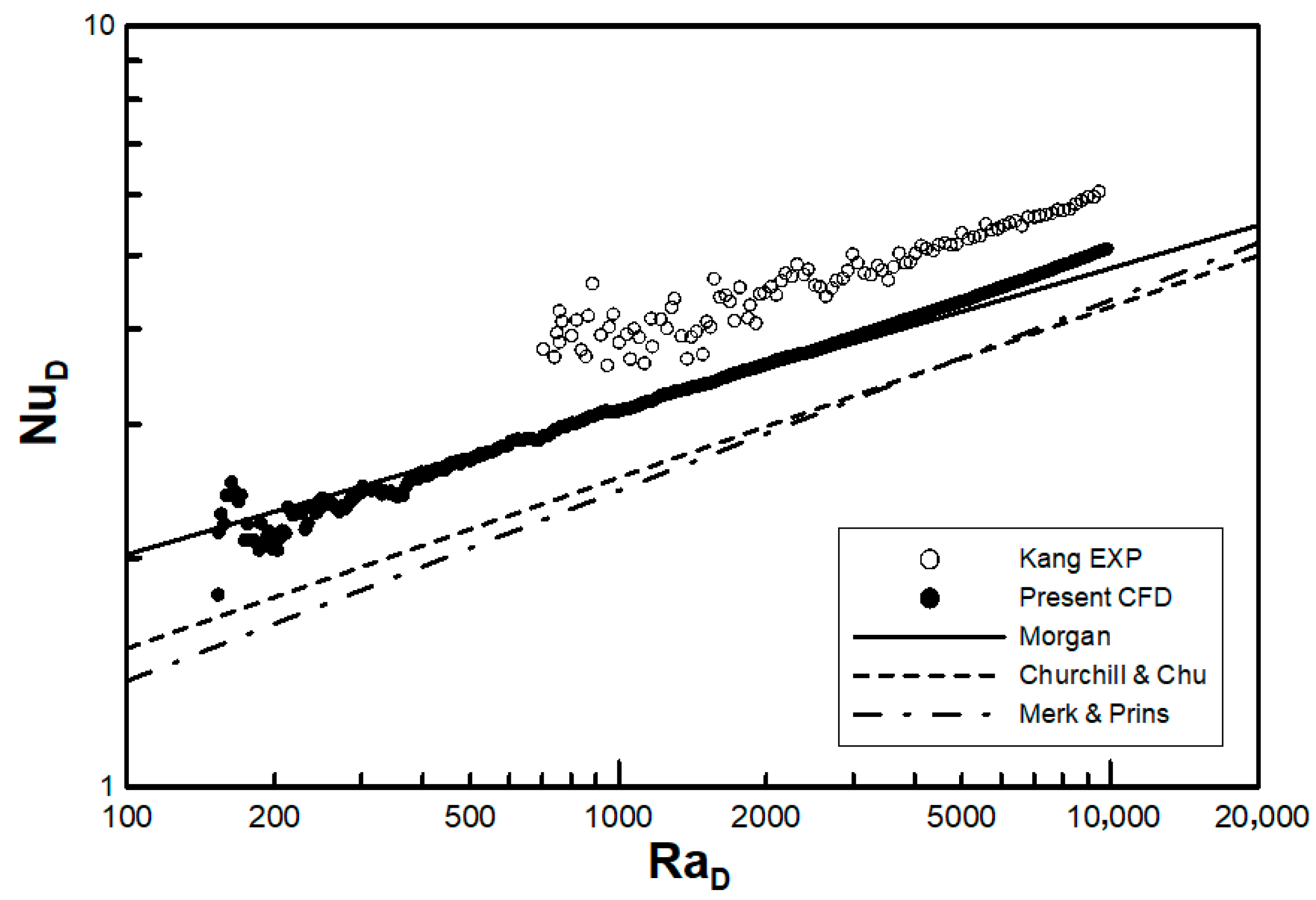
3. Validation of the Computational Fluid Dynamics Method
3.1. Circular Tube
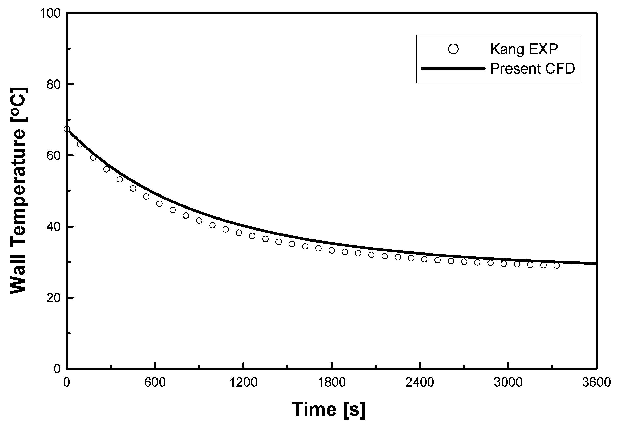
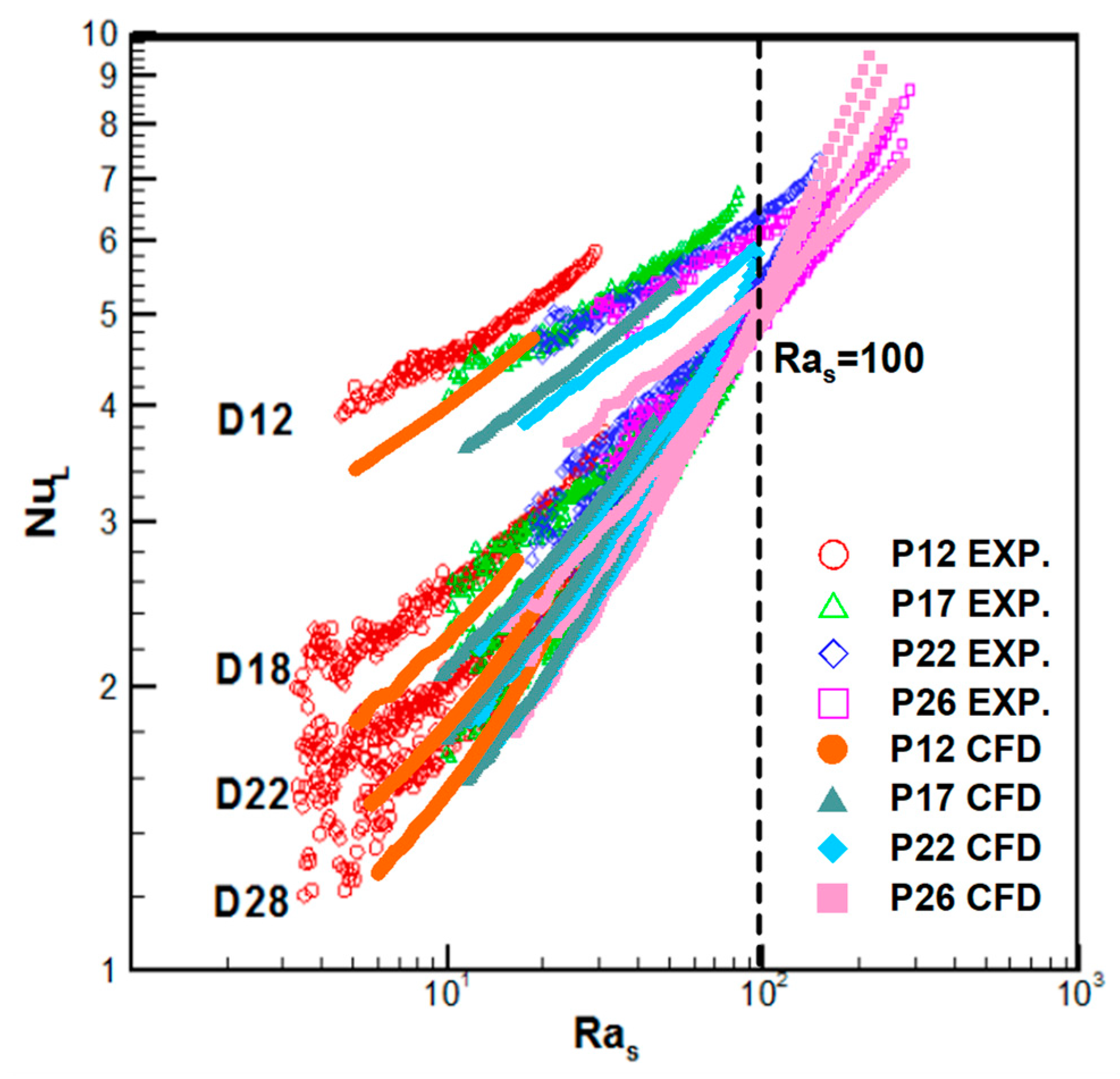
3.2. Comparison with Experimental Data
4. Results and Discussion
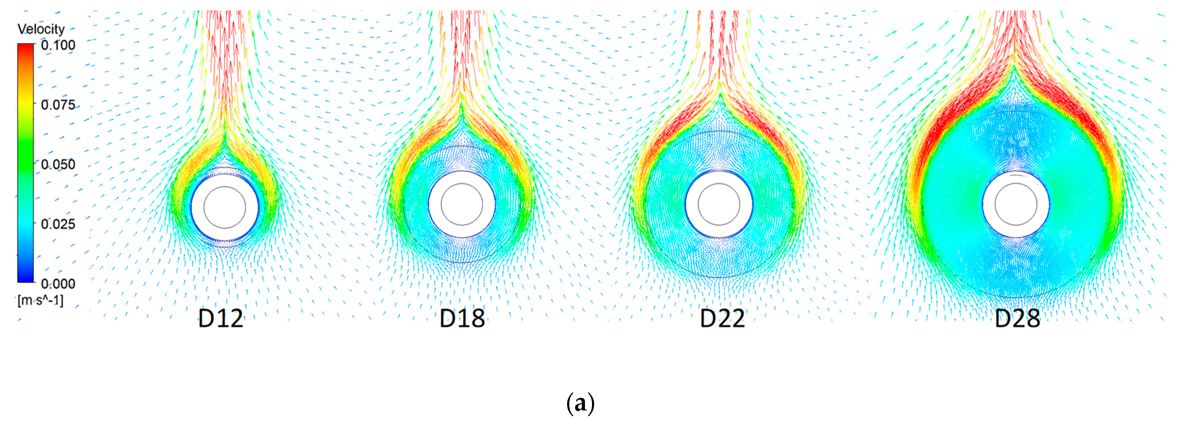
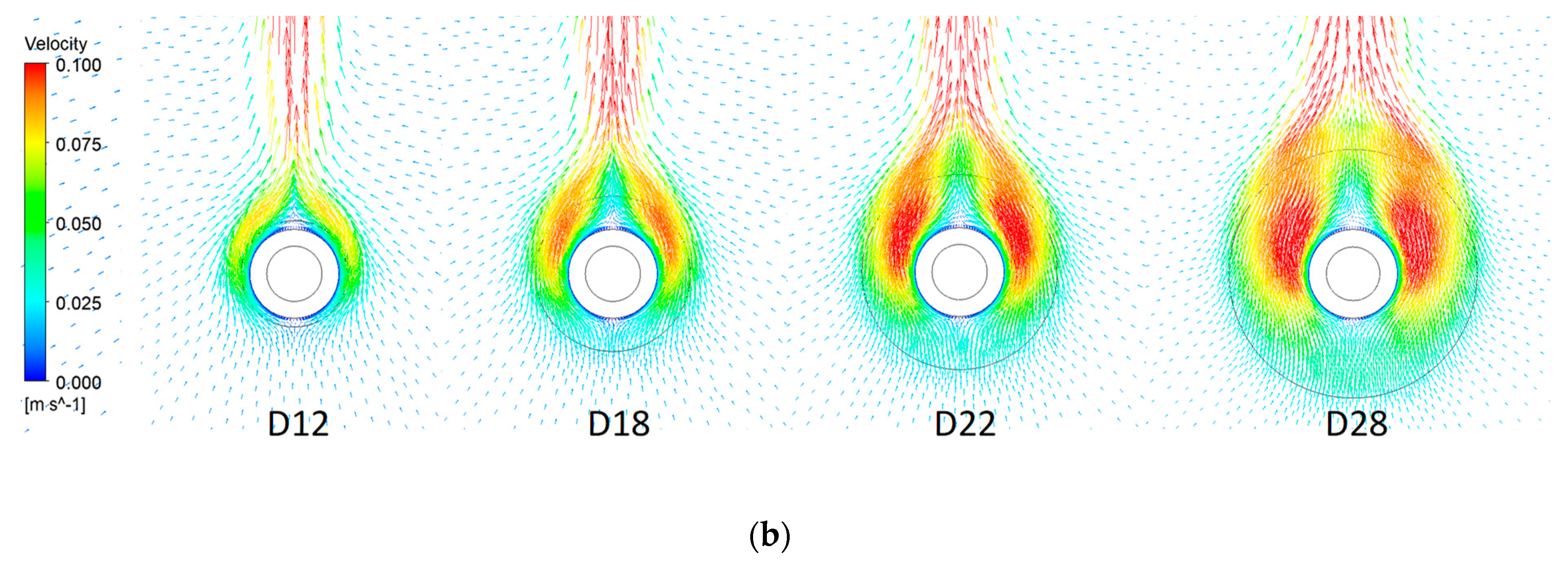
4.1. Velocity
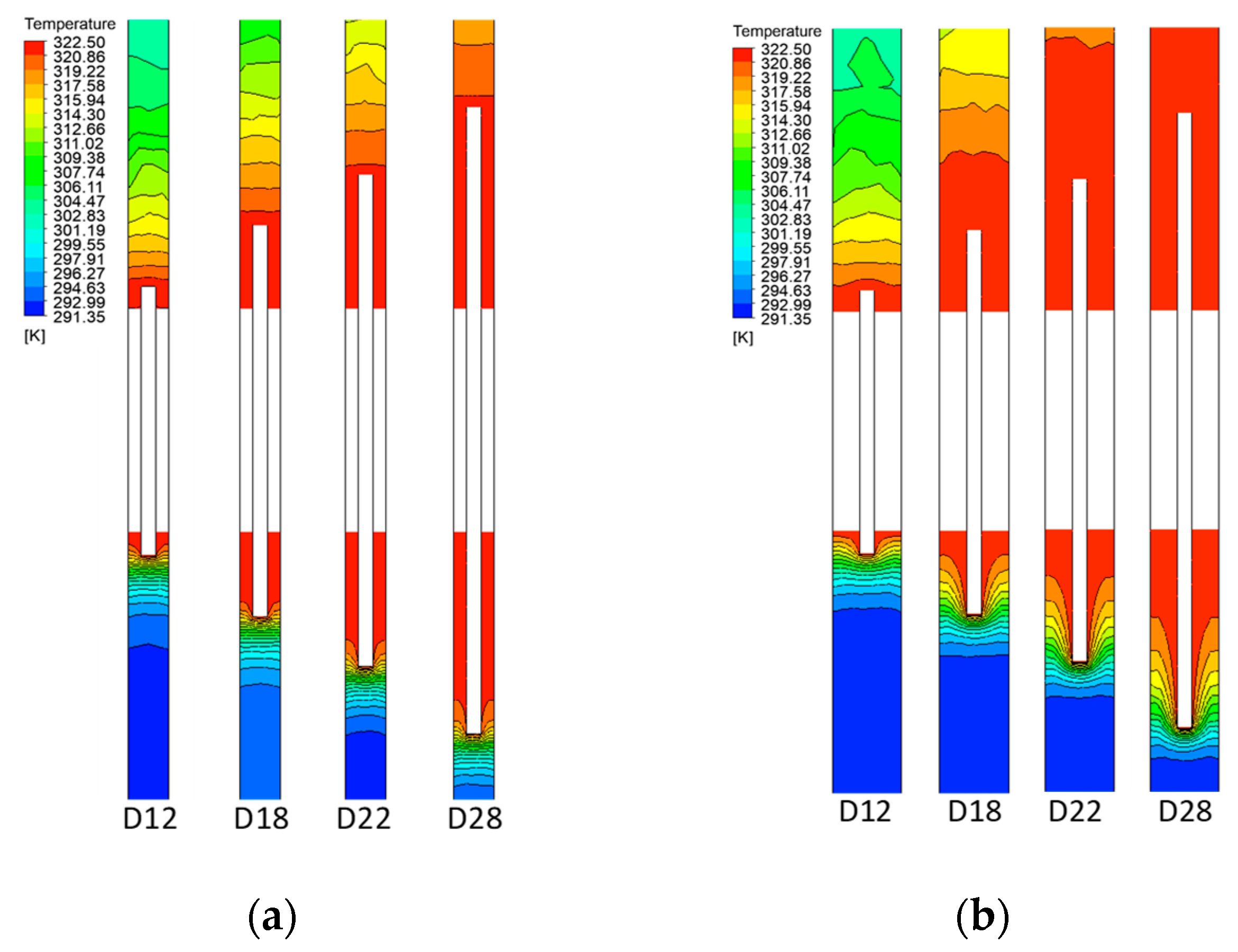
4.2. Temperature
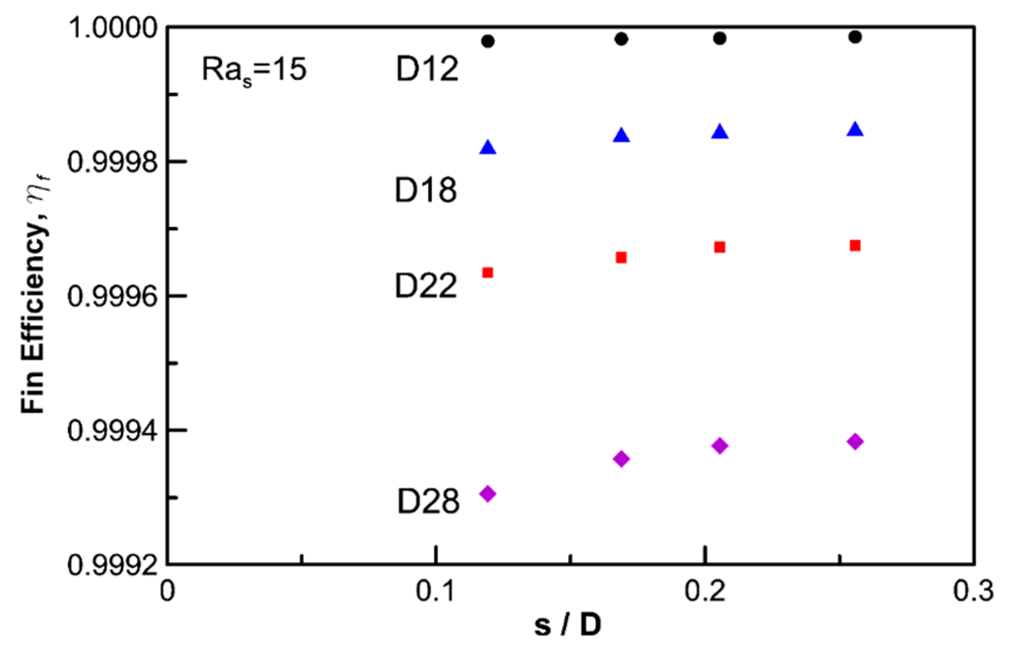
4.3. Fin Efficiency
5. Conclusionsigure
- In a circular fin-tube heat exchanger, the heat transfer of natural convection can be simply expressed via a fin-tube model, and unsteady time marching was proposed to analyze time sweeping for various Ra values. This method is based on practical experiments with lumped temperature.
- Validation of the numerical analysis results via comparisons with empirical correlations such as those of Morgan [2] and Churchill and Chu [3] showed a limited range of errors. The proposed method underpredicted Kang’s experimental values by approximately 16%, but the overall trend coincided with his data. It was considered that the overestimation originated from the additional heat loss, except for the pure natural convection, which served as an artificial cause in the experiment. The accuracy of the natural convection data with the proposed numerical method can be guaranteed when , which is thought to be the limitation of numerical errors due to instability. Small differences in the temperature can affect the data severely. However, the proposed numerical simulation is far more stable than experiments where larger oscillations were observed for higher Ra values (
- The effective limit for a circular fin-tube heat exchanger is reached when because at low Ra values, the air gap between the fins is rarely affected by the natural convection from the outer air or stagnates when the fluid provides heat resistance. Therefore, the fin best serves its purpose when exceeds 100. At low Ra values (), shorter fins or a higher ratio provide better efficiency.
Author Contributions
Funding
Conflicts of Interest
References
- Merk, H.J.; Prins, J.A. Thermal Convection Laminar Boundary Layer III. Appl. Sci. Res. 1954, A4, 207–221. [Google Scholar] [CrossRef]
- Morgan, V.T. The Overall Convective Heat Transfer from Smooth Circular Cylinders. Adv. Heat Transf. 1975, 11, 199–264. [Google Scholar]
- Churchill, S.W.; Chu, H.S. Correlating Equations for Laminar and Turbulent Free Convection from a Horizontal Cylinder. J. Heat Mass Transf. 1975, 18, 1049–1053. [Google Scholar] [CrossRef]
- Zafar, H.; Ahmad, R. Natural Convection from Uniform Heat Flux Horizontal Cylinder at Moderate Rayleigh Numbers. J. Numer. Heat Transf. 1987, 11, 199–212. [Google Scholar]
- Bassam, A.H. Optimization of Natural Convection Heat Transfer from a Cylinder with High Conductivity Fins. J. Numer. Heat Transf. 2003, 43, 65–82. [Google Scholar]
- Hisham, E.D.; Hisham, E.; Faisal, A.J.; Nawaf, A.S. Natural Convection around Horizontal Tubes with Smooth Rough and Machined Surfaces. J. Heat Transf. Eng. 2006, 27, 68–78. [Google Scholar]
- Chen, H.T.; Hsu, W.L. Estimation of Heat Transfer Coefficient on the Fin of Annular-Finned Tube Heat Exchangers in Natural Convection for Various Fin Spacings. J. Heat Mass Transf. 2007, 50, 1750–1761. [Google Scholar] [CrossRef]
- Kang, H.C.; Jang, H.S. Natural Convection Correlations of Circular Finned Tube Heat Exchanger. In Proceedings of the ASME-JSME-KSME 2011 Joint Fluids Engineering Conference. American Society of Mechanical Engineers Digital Collection, Hamamatsu, Japan, 24–29 July 2011; pp. 4023–4027. [Google Scholar]
- Chen, H.T.; Lin, Y.S.; Chen, P.C.; Chang, J.R. Numerical and Experimental Study of Natural Convection Heat Transfer Characteristics for Vertical Plate Fin and Tube Heat Exchangers with Various Tube Diameters. J. Heat Mass Transf. 2016, 100, 320–331. [Google Scholar] [CrossRef]
- Kang, H.C.; Chang, S.M. The Correlation of Heat Transfer Coefficients for the Laminar Natural Convection in a Circular Finned-Tube Heat Exchanger. J. Heat Transf. 2018, 140, 031801. [Google Scholar] [CrossRef]
- ANSYS CFX Training Manual, Version 11.0; ANSYS: San Diego, CA, USA, 2006.
- Schmidt, T.E. Heat Transfer Calculations for Extended Surfaces. ASRE 1949, 4, 351–357. [Google Scholar]


| Case | D | Do | Pf | t | Do/D | s/D | |
|---|---|---|---|---|---|---|---|
| D12 | P12 | 15.88 | 19.1 | 2.89 | 1.0 | 1.20 | 0.119 |
| P17 | 3.68 | 0.169 | |||||
| P21 | 4.26 | 0.205 | |||||
| P26 | 5.06 | 0.256 | |||||
| D18 | P12 | 27.8 | 2.89 | 1.75 | 0.119 | ||
| P17 | 3.68 | 0.169 | |||||
| P21 | 4.26 | 0.205 | |||||
| P26 | 5.06 | 0.256 | |||||
| D22 | P12 | 15.88 | 34.9 | 2.89 | 1.0 | 2.20 | 0.119 |
| P17 | 3.68 | 0.169 | |||||
| P21 | 4.26 | 0.205 | |||||
| P26 | 5.06 | 0.256 | |||||
| D28 | P12 | 44.5 | 2.89 | 2.80 | 0.119 | ||
| P17 | 3.68 | 0.169 | |||||
| P21 | 4.26 | 0.205 | |||||
| P26 | 5.06 | 0.256 | |||||
© 2020 by the authors. Licensee MDPI, Basel, Switzerland. This article is an open access article distributed under the terms and conditions of the Creative Commons Attribution (CC BY) license (http://creativecommons.org/licenses/by/4.0/).
Share and Cite
Lee, J.H.; Shin, J.-H.; Chang, S.-M.; Min, T. Numerical Analysis on Natural Convection Heat Transfer in a Single Circular Fin-Tube Heat Exchanger (Part 1): Numerical Method. Entropy 2020, 22, 363. https://0-doi-org.brum.beds.ac.uk/10.3390/e22030363
Lee JH, Shin J-H, Chang S-M, Min T. Numerical Analysis on Natural Convection Heat Transfer in a Single Circular Fin-Tube Heat Exchanger (Part 1): Numerical Method. Entropy. 2020; 22(3):363. https://0-doi-org.brum.beds.ac.uk/10.3390/e22030363
Chicago/Turabian StyleLee, Jong Hwi, Jong-Hyeon Shin, Se-Myong Chang, and Taegee Min. 2020. "Numerical Analysis on Natural Convection Heat Transfer in a Single Circular Fin-Tube Heat Exchanger (Part 1): Numerical Method" Entropy 22, no. 3: 363. https://0-doi-org.brum.beds.ac.uk/10.3390/e22030363