In Situ Coupling of Ultrasound to Electro- and Photo-Deposition Methods for Materials Synthesis


Abstract
:1. Introduction
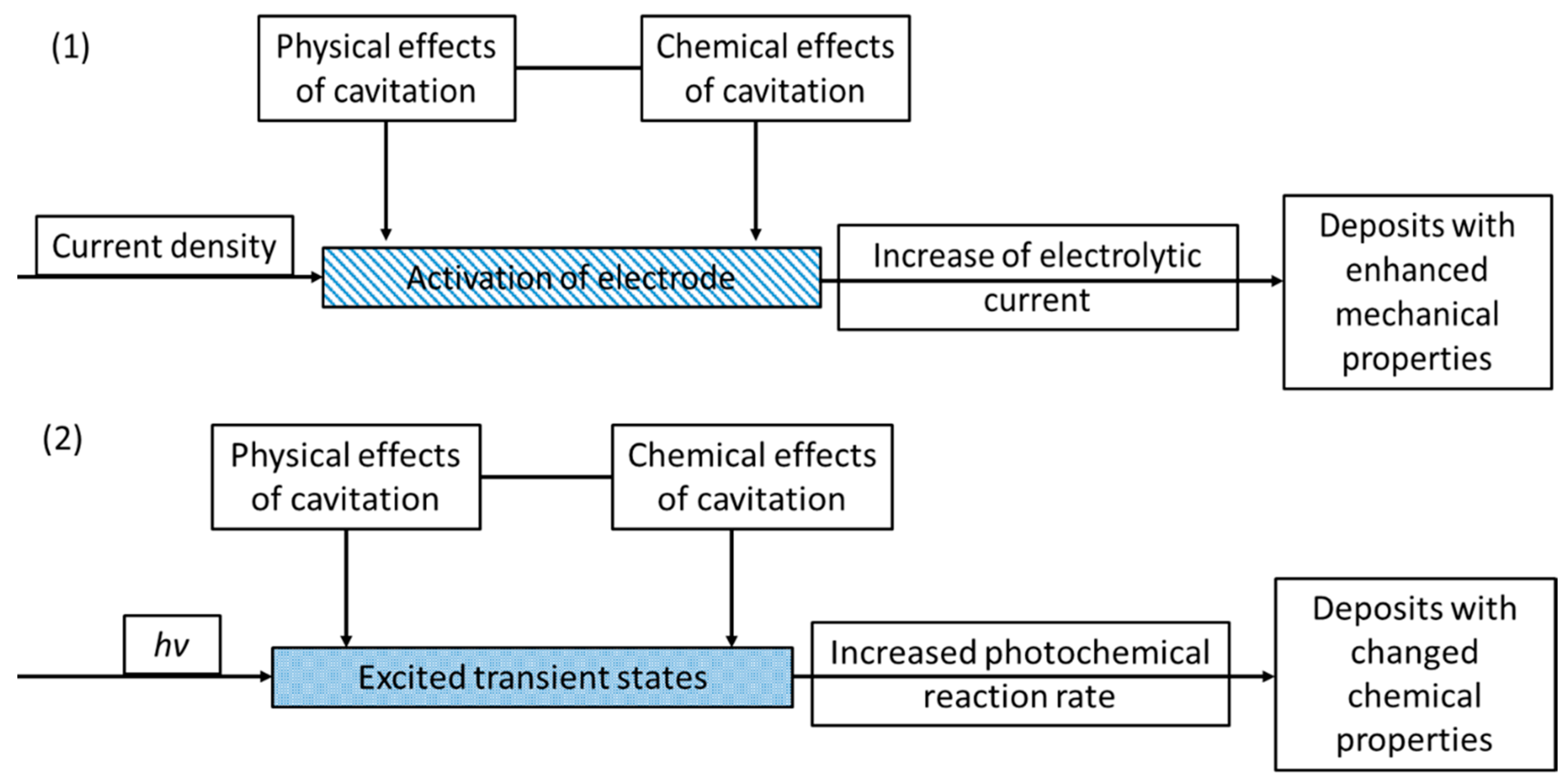
2. Mechanism of Sonoelectrodeposition and Sonophotodeposition Processes
3. Materials Obtained by the Sonoelectrodeposition and Sonophotodeposition Processes
4. Final Remarks
Acknowledgments
Conflicts of Interest
References
- Klima, J. Application of ultrasound in electrochemistry. An overview of mechanisms and design of experimental arrangement. Ultrasonics 2011, 51, 202–209. [Google Scholar] [CrossRef]
- Compton, R.G.; Eklund, J.C.; Marken, F. Sonoelectrochemical processes: A review. Electroanalysis 1997, 9, 509–522. [Google Scholar] [CrossRef]
- Compton, R.G.; Dryfe, R.A.W. Photoelectrochemical studies. Prog. React. Kinet. 1995, 20, 245–307. [Google Scholar]
- Gonzalez-Garcia, J. Sonoelectrochemical synthesis of materials. In Theoretical and Experimental Sonochemistry Involving Inorganic Systems; Pankaj, Ashokkumar, M., Eds.; Springer: Dordrecht, The Netherlands, 2011; pp. 107–129. [Google Scholar]
- Gedanken, A. Sonochemistry and its application to nanochemistry. Current Science 2003, 85, 1720–1722. [Google Scholar]
- Rosenthal, I.; Sostaric, J.Z.; Riesz, P. Enlightened sonochemistry. Res. Chem. Intermed. 2004, 30, 685–701. [Google Scholar] [CrossRef]
- Gonzalez-Garcia, J.; Esclapez, M.D.; Bonete, P.; Hernandez, Y.V.; Garreton, L.G.; Saez, V. Current topics on sonoelectrochemistry. Ultrasonics 2010, 50, 318–322. [Google Scholar] [CrossRef] [PubMed]
- Eklund, J.C.; Marken, F.; Waller, D.N.; Compton, R.G. Voltammetry in the presence of ultrasound: A novel sono-electrode geometry. Electrochim. Acta 1996, 41, 1541–1547. [Google Scholar] [CrossRef]
- Hagan, C.R.S.; Coury, L.A. Comparison of hydrodynamic voltammetry implemented by sonication to a rotating-disk electrode. Anal. Chem. 1994, 66, 399–405. [Google Scholar] [CrossRef]
- Benjamin, T.B. Solitary and periodic waves of a new kind. Philos. T. Roy. Soc. A 1996, 354, 1775–1806. [Google Scholar] [CrossRef]
- Compton, R.G.; Eklund, J.C.; Marken, F.; Rebbitt, T.O.; Akkermans, R.P.; Waller, D.N. Dual activation: Coupling ultrasound to electrochemistry—An overview. Electrochim. Acta 1997, 42, 2919–2927. [Google Scholar] [CrossRef]
- Macounova, K.; Klima, J.; Bernard, C.; Degrand, C. Ultrasound-assisted anodic oxidation of diuron. J. Electroanal. Chem. 1998, 457, 141–147. [Google Scholar] [CrossRef]
- Madigan, N.A.; Hagan, C.R.S.; Coury, L.A. Preparation of microarray electrodes by sonochemical ablation of polymer-films. J. Electrochem. Soc. 1994, 141, L23–L24. [Google Scholar] [CrossRef]
- Klima, J.; Bernard, C. Sonoassisted electrooxidative polymerisation of salicylic acid: Role of acoustic streaming and microjetting. J. Electroanal. Chem. 1999, 462, 181–186. [Google Scholar] [CrossRef]
- Zhang, H.H.; Coury, L.A. Effects of high-intensity ultrasound on glassy-carbon electrodes. Anal. Chem. 1993, 65, 1552–1558. [Google Scholar] [CrossRef]
- Gonzalez-Garcia, J.; Iniesta, J.; Aldaz, A.; Montiel, V. Effects of ultrasound on the electrodeposition of lead dioxide on glassy carbon electrodes. New J. Chem. 1998, 22, 343–347. [Google Scholar] [CrossRef]
- Gonzalez-Garcia, J.; Saez, V.; Iniesta, J.S.; Montiel, V.; Aldaz, A. Electrodeposition of PbO2 on glassy electrodes: Influence of ultrasound carbon power. Electrochem. Commun. 2002, 4, 370–373. [Google Scholar] [CrossRef]
- Saez, V.; Gonzalez-Garcia, J.; Iniesta, J.D.; Frias-Ferrer, A.; Aldaz, A. Electrodeposition of PbO2 on glassy carbon electrodes: Influence of ultrasound frequency. Electrochem. Commun. 2004, 6, 757–761. [Google Scholar] [CrossRef]
- Mallik, A.; Bankoti, A.; Ray, B.C. A study on the modification of conventional electrochemical crystallization under sonication: The phenomena of secondary nucleation. Electrochem. Solid St. 2009, 12, F46–F49. [Google Scholar] [CrossRef]
- Banks, C.E.; Compton, R.G. Ultrasonically enhanced voltammetric analysis and applications: An overview. Electroanalysis 2003, 15, 329–346. [Google Scholar] [CrossRef]
- Lorimer, P.; Mason, T.J. The applications of ultrasound in electroplating. Electrochemistry 1999, 67, 924–930. [Google Scholar]
- Walker, R. Ultrasound and electroplating. Chem. Brit. 1990, 26, 251–254. [Google Scholar]
- Walker, R.; Walker, C.T. New explanation for brightness of electrodeposits produced by ultrasound. Ultrasonics 1975, 13, 79–82. [Google Scholar] [CrossRef]
- Toma, S.; Gaplovsky, A.; Luche, J.L. The effect of ultrasound on photochemical reactions. Ultrason. Sonochem. 2001, 8, 201–207. [Google Scholar] [CrossRef]
- Saez, V.; Esclapez, M.D.; Frias-Ferrer, A.J.; Bonete, P.; Tudela, I.; Diez-Garcia, M.I.; Gonzalez-Garcia, J. Lead dioxide film sonoelectrodeposition in acidic media: Preparation and performance of stable practical anodes. Ultrason. Sonochem. 2011, 18, 873–880. [Google Scholar] [CrossRef] [PubMed]
- Pollet, B.G.; Valzer, E.F.; Curnick, O.J. Platinum sonoelectrodeposition on glassy carbon and gas diffusion layer electrodes. Int. J. Hydrogen Energy 2011, 36, 6248–6258. [Google Scholar] [CrossRef]
- Pollet, B.G. A novel method for preparing pemfc electrodes by the ultrasonic and sonoelectrochemical techniques. Electrochem. Commun. 2009, 11, 1445–1448. [Google Scholar] [CrossRef]
- Heli, H.; Sattarahmady, N.; Vais, R.D.; Mehdizadeh, A.R. Enhanced electrocatalytic reduction and highly sensitive nonenzymatic detection of hydrogen peroxide using platinum hierarchical nanoflowers. Sensor. Actuat. B-Chem. 2014, 192, 310–316. [Google Scholar] [CrossRef]
- Taguchi, M.; Schwalb, N.; Rong, Y.; Vanegas, D.C.; Garland, N.; Tan, M.; Yamaguchi, H.; Claussen, J.C.; McLamore, E.S. Pulsed: Pulsed sonoelectrodeposition of fractal nanoplatinum for enhancing amperometric biosensor performance. Analyst 2016, 141, 3367–3378. [Google Scholar] [CrossRef] [PubMed]
- Han, H.M.; Mikhalovsky, S.V.; Phillips, G.J.; Lloyd, A.W. Calcium phosphate sonoelectrodeposition on carbon fabrics and its effect on osteoblast cell viability in vitro. New Carbon Mater. 2007, 22, 121–125. [Google Scholar] [CrossRef]
- Han, H.M.; Phillips, G.J.; Mikhalovsky, S.V.; FitzGerald, S.; Lloyd, A.W. Sonoelectrochemical deposition of calcium phosphates on carbon materials: Effect of current density. J. Mater. Sci.-Mater. M. 2008, 19, 1787–1791. [Google Scholar] [CrossRef] [PubMed]
- Liu, H.R.; Xia, L.L.; Dai, Y.; Zhao, M.; Zhou, Z.; Liu, H.B. Fabrication and characterization of novel hydroxyapatite/porous carbon composite scaffolds. Mater. Lett. 2012, 66, 36–38. [Google Scholar] [CrossRef]
- Zhao, X.N.; Li, H.J.; Chen, M.D.; Li, K.Z.; Lu, J.H.; Zhang, L.L.; Cao, S. Nano/micro-sized calcium phosphate coating on carbon/carbon composites by ultrasonic assisted electrochemical deposition. Surf. Interface Anal. 2012, 44, 21–28. [Google Scholar] [CrossRef]
- Wang, C.L.; Sun, L.; Yun, H.; Li, J.; Lai, Y.K.; Lin, C.J. Sonoelectrochemical synthesis of highly photoelectrochemically active TiO2 nanotubes by incorporating CdS nanoparticles. Nanotechnology 2009, 20, 295601. [Google Scholar] [CrossRef] [PubMed]
- Mallik, A.; Ray, B.C. Residual stress and nanomechanical properties of sonoelectrodeposited Cu films. Surf. Eng. 2011, 27, 551–556. [Google Scholar] [CrossRef]
- Mallik, A.; Ray, B.C. Morphological study of electrodeposited copper under the influence of ultrasound and low temperature. Thin Solid Films 2009, 517, 6612–6616. [Google Scholar] [CrossRef]
- Hostert, L.; de Alvarenga, G.; Marchesi, L.F.; Soares, A.L.; Vidotti, M. One-pot sonoelectrodeposition of poly(pyrrole)/prussian blue nanocomposites: Effects of the ultrasound amplitude in the electrode interface and electrocatalytical properties. Electrochim. Acta 2016, 213, 822–830. [Google Scholar] [CrossRef]
- Hostert, L.; de Alvarenga, G.; Vidotti, M.; Marchesi, L.F. Sonoelectrodeposition of poly(pyrrole) films: Electrochemical and morphological effects caused by the ultrasonic amplitude. J. Electroanal. Chem. 2016, 774, 31–35. [Google Scholar] [CrossRef]
- Luong, N.H.; Hai, N.H.; Phu, N.D.; MacLaren, D.A. Co-Pt nanoparticles encapsulated in carbon cages prepared by sonoelectrodeposition. Nanotechnology 2011, 22, 285603. [Google Scholar] [CrossRef] [PubMed]
- Luong, N.H.; Trung, T.T.; Loan, T.P.; Kien, L.M.; Hong, T.T.; Nam, N.H. Magnetic properties of FePd nanoparticles prepared by sonoelectrodeposition. J. Electron. Mater. 2016, 45, 4309–4313. [Google Scholar] [CrossRef]
- Nam, N.H.; Nguyen, T.T.V.; Phu, N.D.; Hong, T.T.; Hai, N.H.; Luong, N.H. Magnetic properties of FePt nanoparticles prepared by sonoelectrodeposition. J. Nanomaterials 2012. [Google Scholar] [CrossRef]
- Chang, L.M.; Guo, H.F.; An, M.Z. Electrodeposition of Ni-Co/Al2O3 composite coating by pulse reverse method under ultrasonic condition. Mater. Lett. 2008, 62, 3313–3315. [Google Scholar] [CrossRef]
- Zheng, H.Y.; An, M.Z.; Lu, J.F. Surface characterization of the Zn-Ni-Al2O3 nanocomposite coating fabricated under ultrasound condition. Appl. Surf. Sci. 2008, 254, 1644–1650. [Google Scholar] [CrossRef]
- Zheng, H.-Y.; An, M.-Z. Electrodeposition of Zn-Ni-Al2O3 nanocomposite coatings under ultrasound conditions. J. Alloys Compd. 2008, 459, 548–552. [Google Scholar] [CrossRef]
- Cheng, J.Q.; Yao, S.W. Synthesis and characterization of silver nanoparticles by sonoelectrodeposition. Rare Met. 2005, 24, 376–380. [Google Scholar]
- Tuan, T.Q.; Son, N.V.; Hoang, T.K.D.; Luong, N.H.; Thuy, B.T.; Nguyen, T.V.A.; Hoa, N.D.; Hai, N.H. Preparation and properties of silver nanoparticles loaded in activated carbon for biological and environmental applications. J. Hazard. Mater. 2011, 192, 1321–1329. [Google Scholar] [CrossRef] [PubMed]
- Rahi, A.; Sattarahmady, N.; Vais, R.D.; Heli, H. Sonoelectrodeposition of gold nanorods at a gold surface—Application for electrocatalytic reduction and determination of nitrofurazone. Sensor. Actuat. B-Chem. 2015, 210, 96–102. [Google Scholar] [CrossRef]
- Rousse, C.; Josse, J.; Mancier, V.; Levi, S.; Gangloff, S.C.; Fricoteaux, P. Synthesis of copper-silver bimetallic nanopowders for a biomedical approach; study of their antibacterial properties. RSC Adv. 2016, 6, 50933–50940. [Google Scholar] [CrossRef]
- Zin, V.; Dabala, M. Iron-chromium alloy nanoparticles produced by pulsed sonoelectrochemistry: Synthesis and characterization. Acta Mater. 2010, 58, 311–319. [Google Scholar] [CrossRef]
- Ohsaka, T.; Isaka, M.; Hirano, K.; Ohishi, T. Effect of ultrasound sonication on electroplating of iridium. Ultrason. Sonochem. 2008, 15, 283–288. [Google Scholar] [CrossRef] [PubMed]
- Seetharaman, S.; Balaji, R.; Ramya, K.; Dhathathreyan, K.S.; Velan, M. Electrochemical behaviour of nickel-based electrodes for oxygen evolution reaction in alkaline water electrolysis. Ionics 2014, 20, 713–720. [Google Scholar] [CrossRef]
- Colmenares, J.C.; Magdziarz, A.; Lomot, D.; Chernyayeva, O.; Lisovytskiy, D. A new photocatalytic tool in VOCs abatement: Effective synergetic combination of sonication and light for the synthesis of monometallic palladium-containing TiO2. Appl. Catal., B 2014, 147, 624–632. [Google Scholar] [CrossRef]
- Colmenares, J.C.; Lisowski, P.; Lomot, D.; Chernyayeva, O.; Lisovytskiy, D. Sonophotodeposition of bimetallic photocatalysts Pd-Au/TiO2: Application to selective oxidation of methanol to methyl formate. ChemSusChem 2015, 8, 1676–1685. [Google Scholar] [CrossRef] [PubMed]
- Lisowski, P.; Colmenares, J.C.; Lomot, D.; Chernyayeva, O.; Lisovytskiy, D. Preparation by sonophotodeposition method of bimetallic photocatalysts Pd-Cu/TiO2 for sustainable gaseous selective oxidation of methanol to methyl formate. J. Mol. Catal. A: Chem 2016, 411, 247–256. [Google Scholar] [CrossRef]
- Magdziarz, A.; Colmenares, J.C.; Chernyayeva, O.; Łomot, D.; Sobczak, K. Sonication and light irradiation as green energy sources simultaneously implemented in the synthesis of Pd-Fe- and Pt-Fe-doped TiO2-based photocatalysts. J. Mol. Catal. A: Chem 2016, 425, 1–9. [Google Scholar] [CrossRef]
- Magdziarz, A.; Colmenares, J.C.; Chernyayeva, O.; Kurzydlowski, K.; Grzonka, J. Iron-containing titania photocatalyst prepared by the sonophotodeposition method for the oxidation of benzyl alcohol. ChemCatChem 2016, 8, 536–539. [Google Scholar] [CrossRef]
- Gogate, P.R. Treatment of wastewater streams containing phenolic compounds using hybrid techniques based on cavitation: A review of the current status and the way forward. Ultrason. Sonochem. 2008, 15, 1–15. [Google Scholar] [CrossRef] [PubMed]
- Saterlay, A.J.; Compton, R.G. Sonoelectroanalysis: An overview. Fresenius' J. Anal. Chem. 2000, 367, 308–313. [Google Scholar] [CrossRef]
- Metters, J.P.; Kruusma, J.; Banks, C.E. Sonoelectroanalysis: An overview. In Power Ultrasound in Electrochemistry: From Versatile Laboratory Tool to Engineering Solution; Pollet, B.G., Ed.; John Wiley & Sons, Ltd.: Chichester, UK, 2012; pp. 79–99. [Google Scholar]
- Yaqub, A.; Ajab, H. Applications of sonoelectrochemistry in wastewater treatment system. Rev. Chem. Eng. 2013, 29, 123–130. [Google Scholar] [CrossRef]
- Saez, V.; Mason, T.J. Sonoelectrochemical synthesis of nanoparticles. Molecules 2009, 14, 4284–4299. [Google Scholar] [CrossRef] [PubMed]


| Entry | Type of Material | Synthesis Setup | Characteristics of the Material | Application/Test Reaction | Ref. |
|---|---|---|---|---|---|
| Sonoelectrodeposition | |||||
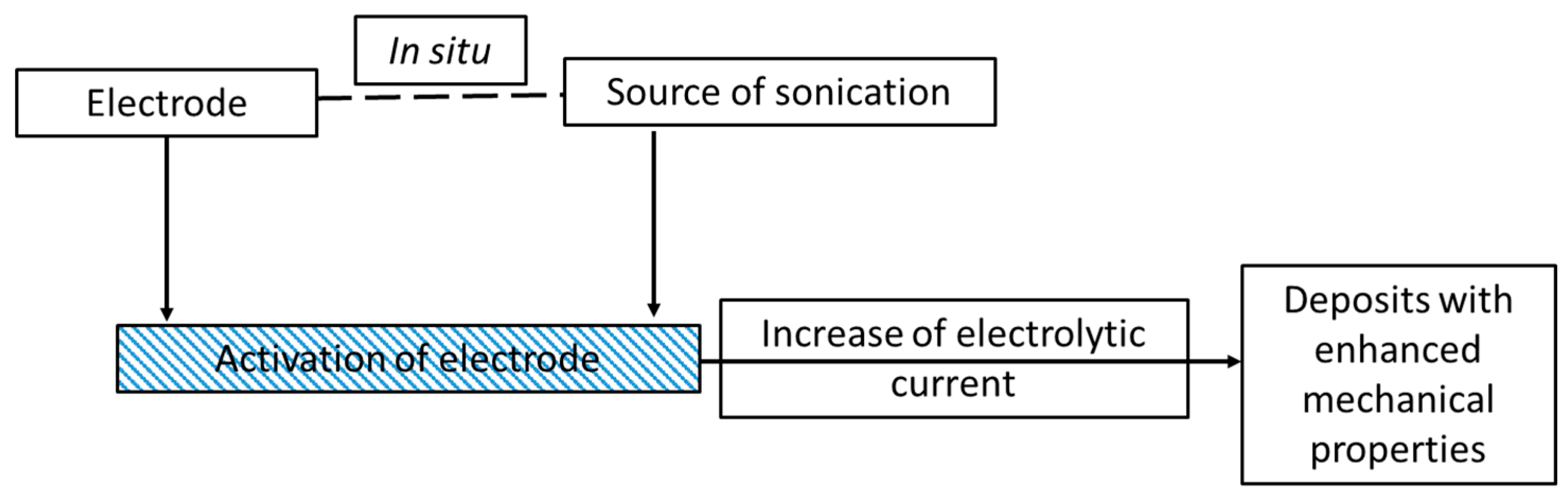
| 1. | PbO2/glassy carbon electrode PbO2/Pt electrode | Ultrasonic bath (30 kHz, 100 W), glassy carbon rod and polyoriented platinum as the working electrodes | The activation of glassy carbon electrode in contrast to platinum electrode. This activation was explained by the formation of surface functional groups, because no change in topography of the electrode surface was seen | Potential application of PbO2 as an anode in: electrochemical degradation, synthesis, batteries, sensors, but not tested by authors | [16] |
| 2. | PbO2/glassy carbon electrode | Sonoreactor (20 kHz, 100 W), glassy carbon rod as the working electrode, platinum wire as the counter electrode, calomel electrode as the reference | The influence of ultrasound frequency on the kinetics of electrodeposition process of lead dioxide was registered. The explanation of this phenomenon was found in the increase of OH• generation | Potential application of PbO2 as an anode in: electrochemical degradation, synthesis, batteries, sensors, but not tested by authors | [17,18] |
| 3. | PbO2/glassy carbon electrode PbO2/Tielectrode | Ultrasonic horn (20 kHz), or ultrasonic bath (40 kHz, 100 W), plates of graphite or titanium as the working electrodes, copper as the counter electrode | Homogeneous, free from stress and nodules. PbO2 film was obtained on both electrodes. A strong improvement in the quality of these deposits, a lower corrosion rate in the accelerated test reactions | Sonoelectrochemical degradation of perchloroethylene (PCE) in sulfate media; electrochemical recovery of zinc | [25] |
| 4. | Pt/glassy carbon electrode (GC) Pt/gas diffusion layer (GDL) | Ultrasonic probe (20 kHz), glass carbon (or carbon gas diffusion layer) as the working electrode | The electrodeposition of Pt was facilitated by a decrease in nucleation overpotentials. Formation of larger nanoparticles and their agglomerates were observed | Potentially as electrodes for PEMFCs and DMFCs, but not tested by the authors | [26] |
| 5. | Platinum nanoflowers | Ultrasonic bath (45 W), Pt working electrode, glassy carbon counter electrode, Ag reference electrode, constant potential 50 mV | Platinum layer built of irregular and fragmentized nanoparticles, gathered in self-affined larger structures, finally forming hierarchical nanoflowers | Non-enzymatic sensor of hydrogen peroxide | [28] |
| 6. | Nanoplatinum fractal structures | Ultrasonic bath, Pt/Ir electrodes as the working electrode, Pt wire as the counter electrode, constant overpotential 10 V | The nanoplatinum displayed: fractal features, homogeneous size distribution and very high electroactive surface. Formation of stable nanostructures were promoted by a high duty cycle (900 mHz) and reduction of amorphous structure due to cavitation effect | Non-enzymatic and enzymatic sensors for measuring hydrogen peroxide and glucose | [29] |
| 7. | CaP/carbon fibers | Ultrasonic bath (40 kHz, 2.16 W/cm2), carbon fabric as the working electrode, constant current density (20 mA/cm2) | Better morphology: a uniform coating with small crystals and good adhesive strength, was obtained under this condition in comparison with a silent mode | Biomedical application: bioceramic composites used for the reconstruction of bone defects | [30] |
| 8. | CaP/carbon fibers | Ultrasonic bath (40 kHz, 2.16 W/cm2), carbon fabric as the working electrode, platinum plate as the counter electrode, different current densities: 5, 8, 13, 20, and 34 mA/cm2 | Different morphology of the CaP coatings depends on the current density. More uniform structures with smaller crystal sizes were obtained at higher values of current density | Biomedical application | [31] |
| 9. | Hydroxyapatite (HA)/porous carbon composite scaffolds | Ultrasonic stirring, porous carbon, constant voltage 3 V | A homogeneous coating with HA crystals across external as well as internal surfaces of the porous carbon scaffold was obtained | Biomedical application: in vitro 3D culture of osteoblasts | [32] |
| 10. | CaP-coated C/C composites | Ultrasonic device (25 kHz, 100 W), C/C electrode as the cathode, graphite as the anode, different voltages: 2.0, 2.4, 2.7, and 3.0 V, controlled temp. 50 ± 3 °C | The most homogeneous coating was obtained at 2.4 V and formed an interlocking structure along the depth direction of the coating without any defects or uncovered areas. This resulted in improved adhesive and cohesive strength of the coating | Biomedical application, especially as dental and medical implant materials | [33] |
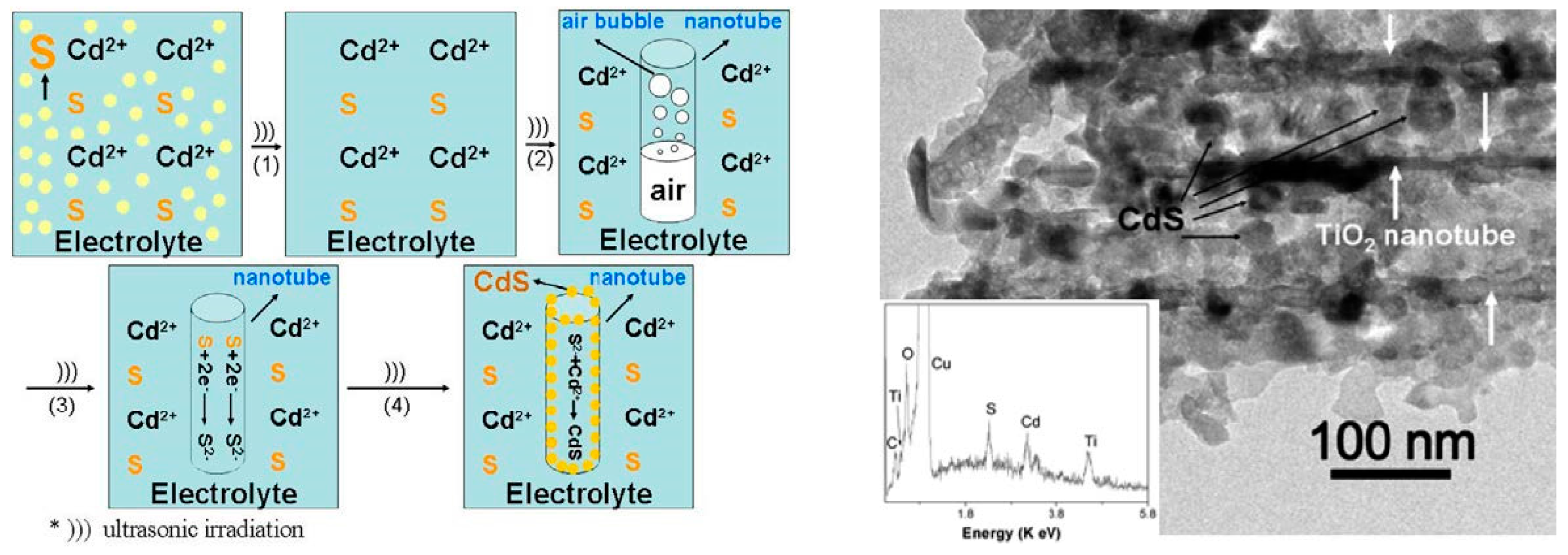
| 11. | CdS/TiO2NT | Ultrasonic bath (40 kHz, 2.4 kW/m2), TiO2 NT as the working electrode, Pt foil as the counter electrode, constant current density (5 mA/cm2), constant temperature 50 °C | TiO2 nanotubes were successfully filled with CdS small-sized nanoparticles with more homogeneous distribution. A stronger photocurrent and extended photoresponse to the visible light were observed for such composites | Potential application in photocatalytic reactions, but not performed by the authors | [34] |
| 12. | Cu/Graphite | Ultrasonic probe (20 kHz, 20% output), graphite electrode as the cathode, Pt electrode as the anode, Ag electrode as the reference electrode, different set of temperatures: 25, 20, 15, 10, and 5 °C | A maximum value of compressive residual stress in the Cu films was registered at 5 °C. This result has a direct influence on the mechanical properties of the film, as the maximum hardness and elasticity occurred also at the lowest deposition temperature | Potential application in electronic industry, but not tested by the authors | [35] |
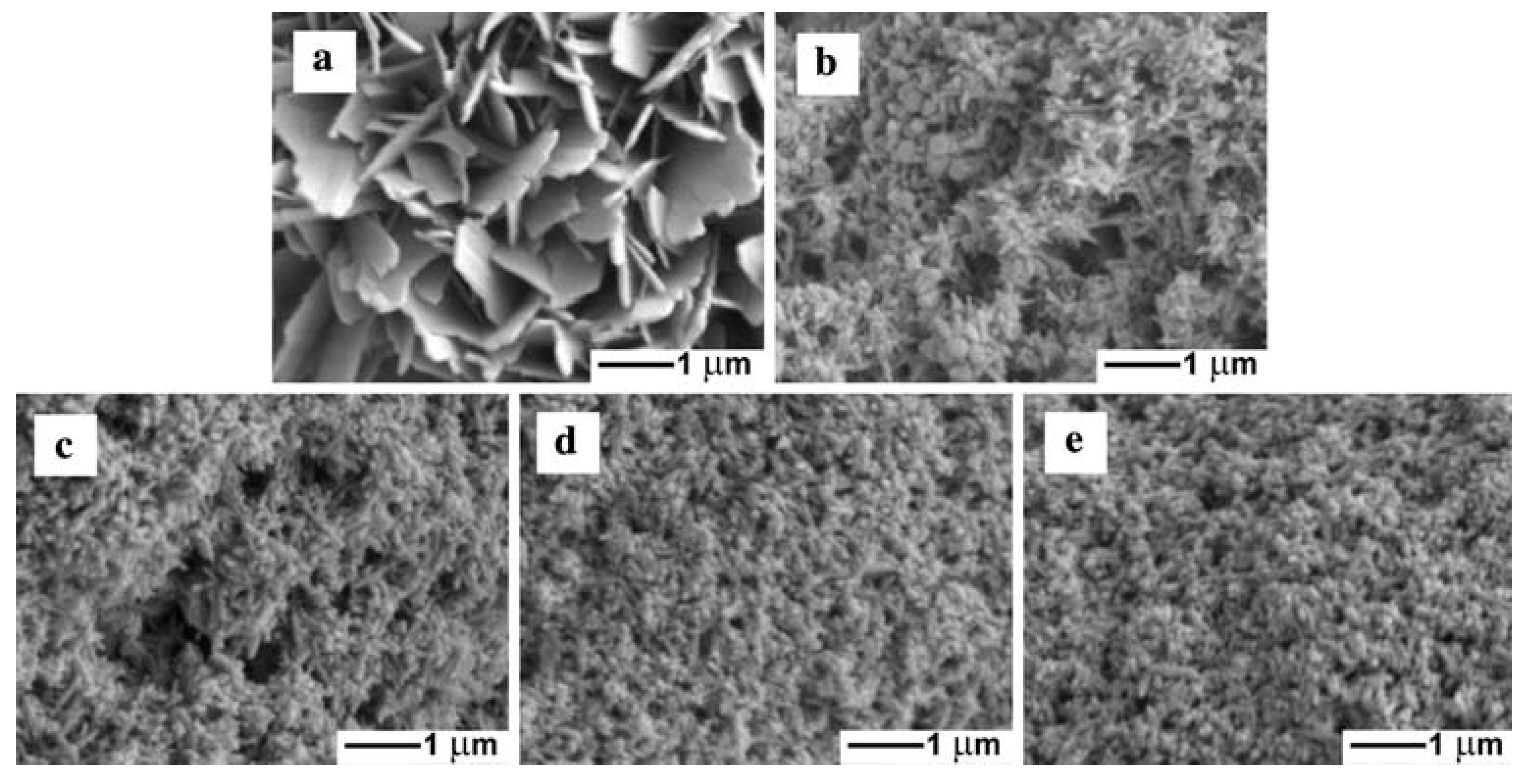
| 13. | Cu/Graphite | Ultrasonic bath (30 kHz, 60 W); graphite electrode as the cathode, copper electrode as the anode, calomel electrode as the reference; temperatures selected for this experiment were as following: 25, 19.5, −1 and −3 °C | Cleaner nanorange deposits of copper were obtained under sonication. Different morphology of Cu films was registered at different deposition temperatures: from inhomogeneously deposited distorted grains at 25 °C to uniform coatings with fine grains at −3 °C | Potential application in electronic industry, but not tested by the authors | [36] |
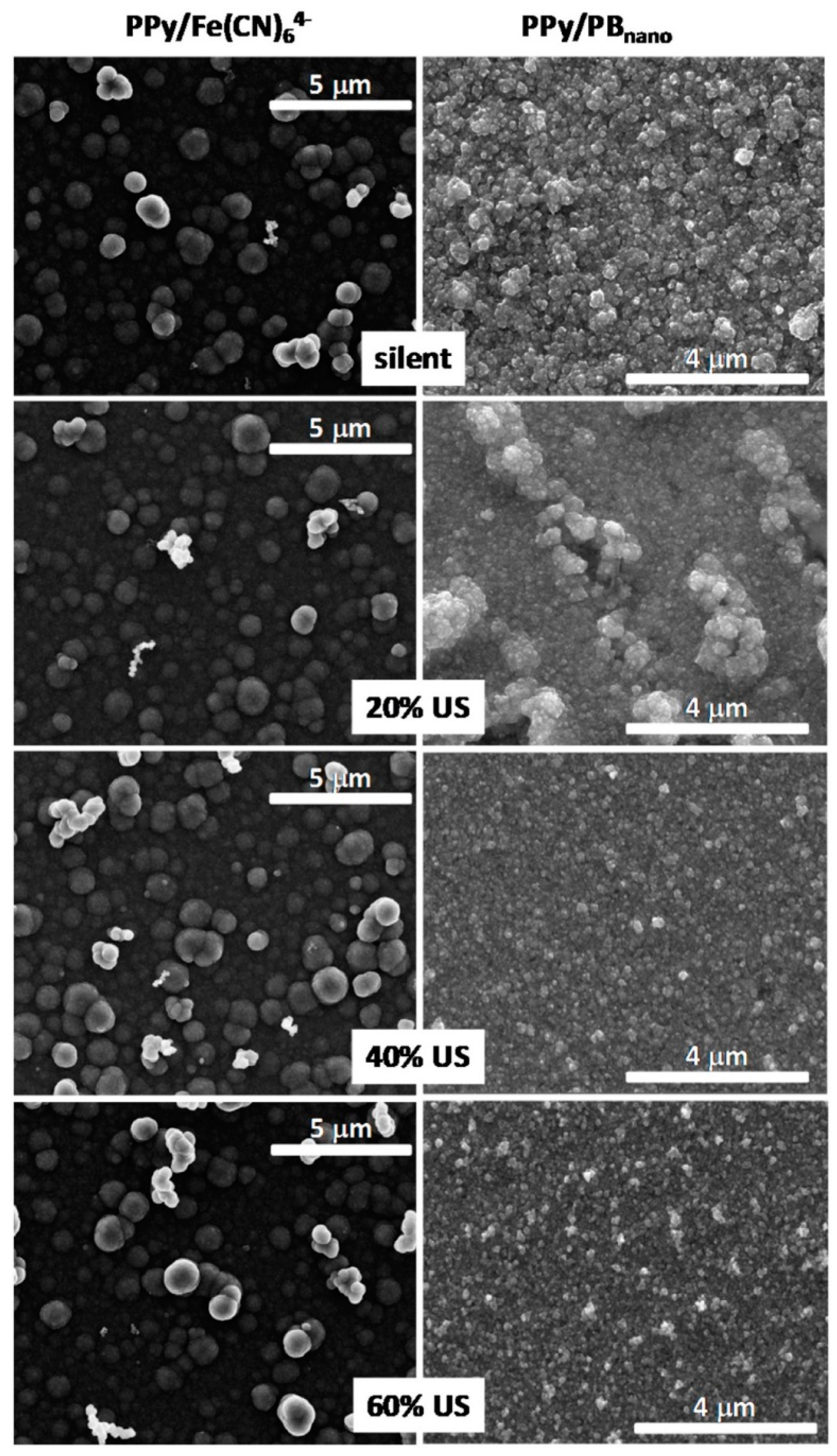
| 14. | Poly(pyrrole)/Prussian blue (PB) nanocomposite | Ultrasonic horn (20 kHz, 130 W) with different amplitudes: 20%, 40%, and 60%; ITO electrodes | With the increasing ultrasound amplitude the morphology of the film changed from large aggregates to small particles homogeneously distributed over the electrode surface | Electrocatalytic reduction of H2O2. Potential application in electrocatalysis (sensors/biosensors) | [37] |
| 15. | Poly(pyrrole)/dodecylbenzenesulphonate (DBS) film | Ultrasonic horn (20 kHz, 130 W) with different amplitudes: 20%, 40%, and 60%; platinum electrode | Different morphology of the films obtained under silent and sonochemical conditions reflected in a distinct voltammetric behavior of electrodes. Diminished the charge-transfer resistance of the films | Potential application as electrochemical based devices: sensors, biosensors and supercapacitors | [38] |
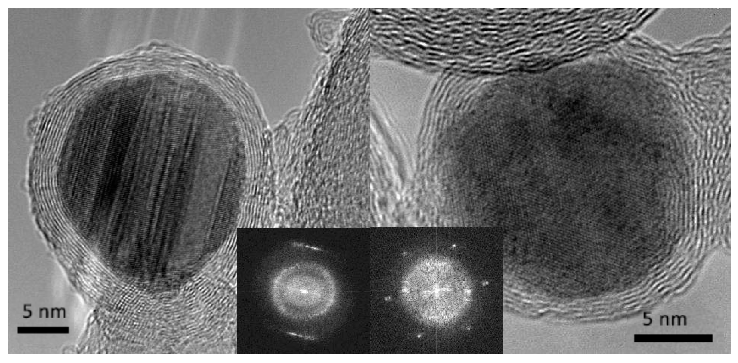
| 16. | Co-Pt NPs | Pulse mode operating ultrasonic horn acted as the cathode and ultrasound emitter, platinum plate as the counter electrode | An ordering of Co-Pt phase, hard magnetic properties and formation of metallic core-carbon onion shell structure after sonoelectrodeposition with annealing in CO atmosphere | Potential magnetic application (e.g., ultrahigh-density magnetic storage media), but not tested by the authors | [39] |
| 17. | FePt NPs | Pulse mode operating ultrasonic horn acted as the cathode and ultrasound emitter, platinum plate as the counter electrode | Improvement of magnetic properties and ordering of crystal structure of FePt were obtained when sonoelectrodeposition was followed by annealing at high temp | Potential magnetic application (e.g., ultrahigh-density magnetic storage media), but not tested by the authors | [41] |
| 18. | FePd NPs | Pulse mode operating ultrasonic horn acted as the cathode and ultrasound emitter, platinum plate as the counter electrode | Sonoelectrodeposition with the following annealing at high temp. resulted in formation of the ordered L10 crystal structure and hard magnetic properties of FePd NPs | Potential magnetic application (e.g., ultrahigh-density magnetic storage media), but not tested by the authors | [40] |
| 19. | Ni-Co/Al2O3 | Ultrasonic power (0–160 W), nickel plate as anode, polished mild steel sheet as cathode, under pulse reverse current | Uniform, compact coating with a fine grains and enhanced mechanical properties | Potential application in automobile/aerospace industry, but not tested by the authors | [42] |
| 20. | Zn-Ni-Al2O3 | Ultrasonic horn (20 kHz, 150 W) with ultrasonic power applied 0.7 W/cm2, Zn plate as the anode, Cu as the cathode | Uniform dispersion of nano-alumina in the Zn-Ni matrix. Different composition of the composite layers: the outermost layer consists of Al2O3 and Zn(OH)2 while transitional layer contains Al2O3, ZnO, Zn, and Ni | Potential application as anti-corrosion coatings | [43] |
| 21. | Zn-Ni-Al2O3 | Ultrasonic horn (20 kHz, 150 W) different ultrasonic power applied (from 0 W/cm2 to 1.2 W/cm2), Zn plate as the anode | Increased content and more uniform dispersion of nano-alumina particles resulted in improved anticorrosion property and hardness of the composite coating (0.7 W/cm2) | Potential application as anti-corrosion coatings | [44] |
| 22. | Ag NPs | Ultrasonic bath (20 kHz, 100 W), stainless steel as a the cathode, Ru-Ti alloy as a the counter electrode, controlled-current 60 mA | Shaped silver NPs were obtained: spheres with a diameter about 30 nm, wires with a diameter 30 nm and length 200–900 nm and dendrites, formed with increasing concentration of silver solution | Potential application in microelectronics, optical, electronics, magnetic devices, but not tested by the authors | [45] |
| 23. | Ag NPs loaded on active carbon | Sonicator working in a pulse mode, silver plate used as the cathode, platinum plate as the anode | Ag NPs with the size of 4–30 nm dispersed in a non-toxic solution due to the use of silver plate as a source of silver ions. In the next step Ag NPs were loaded on the surface of active carbon | Antibacterial activity against Escherichia coli | [46] |
| 24. | Au nanorods deposited on gold surface (Au-Au NR) | Ultrasonic bath (45 W) and working Au electrode | Special size, shape and structure of nanorods were obtained: a width of 80–120 nm, a length of 140–370 nm, and an aspect ratio of 1.6–3.5 | Nitrofurazone sensor | [47] |
| 25. | Cu-Ag NPs | Ultrasonic horn with titanium probe used as the working electrode working in a pulse mode; copper rod as the counter electrode, saturated mercury sulfate as the reference electrode | Cu core-Ag shell structure (7 nm diameter of NPs) obtained by combination of sonoelectrodeposition for the inner core and galvanic replacement reaction for outer shell | Bactericidal properties against Staphylococus aureus and Escherichia coli bacteria | [48] |
| 26. | Fe-Cr alloy NPs | Ultrasonic horn with titanium probe used as the working electrode working in a pulse mode (20 kHz); platinum net used as the counter electrode | Process efficiency decreases with increasing temperature of the electrolyte. Structural and morphological features of the NPs are not influenced by the synthesis temperature. The crystalline structure of NPs depends on the electrolyte’s composition | Potential technological application (good mechanical, anti-corrosive and water-resistant properties), but not tested by the authors | [49] |
| 27. | Iridium NPs on a copper plate | Ultrasonic homogenizer (20 kHz), copper plate as the cathode, platinum plate as the anode | Reduced defects, including cracks in the iridium deposits. Accelerated rate of iridium deposition | Potential industrial and chemical application (as an inert material), but not tested by the authors | [50] |
| 28. | NiZnS alloy | Ultrasound irradiation of 20 kHz at different current densities, pulse electrodeposition at various duty cycles at 10 Hz; nickel mesh electrode | The smallest size of deposit particles (17 nm), uniform coatings in fine-grained structures of the alloy, better surface morphology, the highest surface area, the highest exchange current density (8.25 × 10⁻³ A/cm2) and high current density (0.42 A/cm2) were achieved in pulse sonoelectrodeposited electrodes | Oxygen evolution reaction (OER) in alkaline media | [51] |
| Sonophotodeposition | |||||
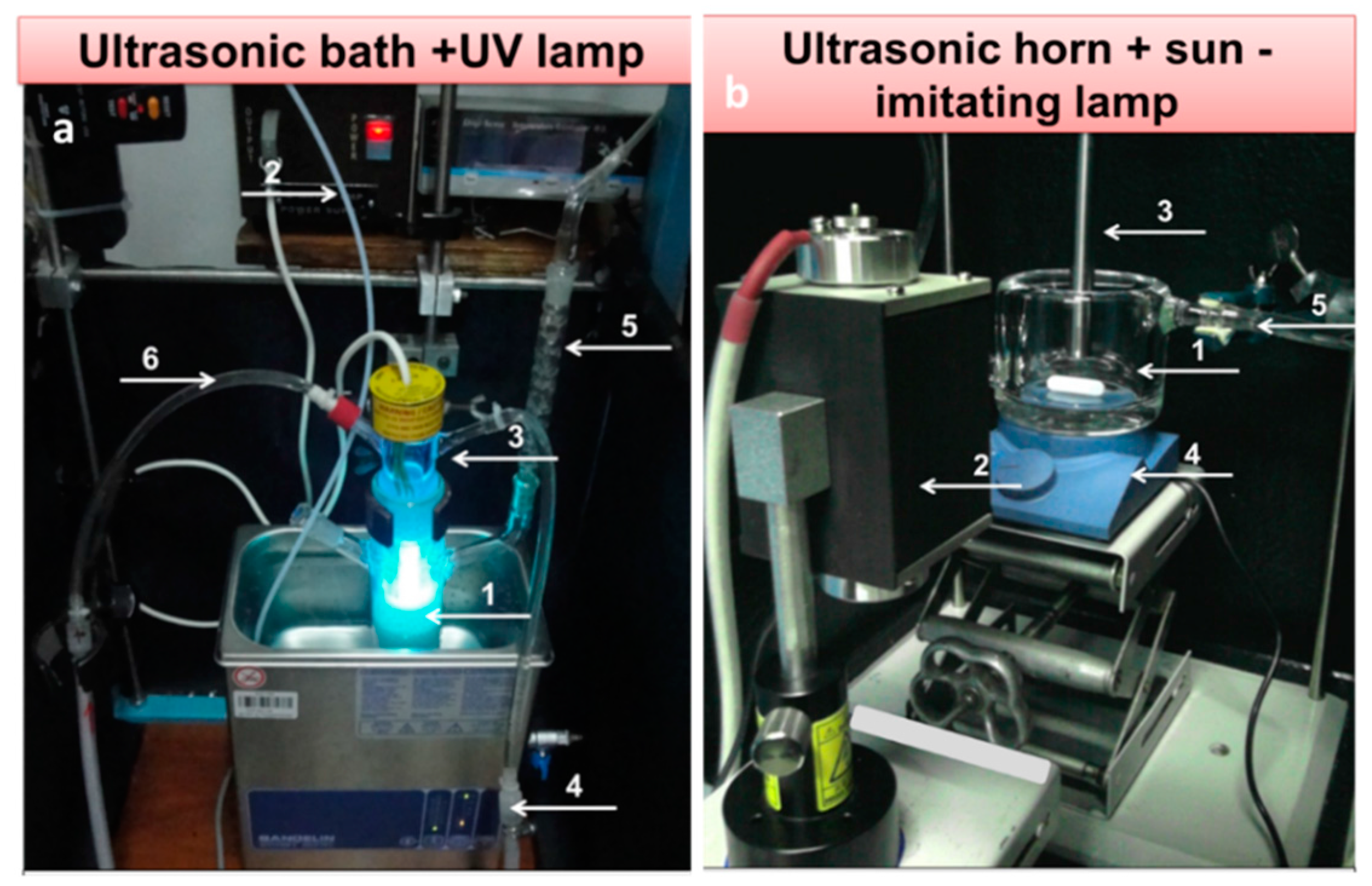
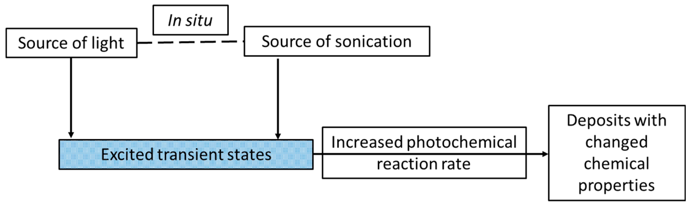
| 29. | Pd/TiO2P90 | Ultrasonic bath and 6 W Hg lamp (λmax = 254 nm) | Total reduction of palladium, despite the air calcination step. In contrast, surface PdO forms were detected in the material prepared by pure photodeposition. This confirmed the role of sonication in the reduction process | Gas phase photocatalytic degradation of methanol | [52] |
| 30. | Pd-Au/TiO2P90 | Ultrasonic bath and 6 W Hg lamp (λmax = 254 nm) | Formation of random alloys between Pd-Au NPs and SMSI effect between NPs and TiO2 for one specified composition of metals: 1 wt% Pd50-Au50/TiO2 P90 | Gas phase selective photocatalytic oxidation of methanol to methyl formate. | [53] |
| 31. | Pd-Cu/TiO2P90 | Ultrasonic bath and 6 W Hg lamp (λmax = 254 nm) | SMSI effect between Pd-Cu NPs and TiO2 for one specified composition of metals: 1 wt% Pd-Cu(1-1)/TiO2 P90. Retarding effect of Cu on total reduction of Pd | Gas phase selective photocatalytic oxidation of methanol to methyl formate | [54] |
| 32. | Pd-Fe/TiO2/Zeolite YPt-Fe/TiO2/Zeolite Y | Ultrasonic bath and 6 W Hg lamp (λmax = 254 nm) | Mainly Pt° and Fe3+ in Pt-Fe/TiO2/Ze and Pd2+ and Fe3+ in Pd-Fe/TiO2/Ze were formed (reduction potentials dependency). A very good dispersion and control over the particle size in the case of Pt nanoparticles | Liquid-phase photocatalytic oxidation of phenol under UV lamp | [55] |
| 33. | Fe/TiO2/Zeolite Y | Ultrasonic horn (20 kHz, 700 W, 25% of amplitude) and sun-imitating Xenon lamp (240–2000 nm) | 4–5 nm sized Fe3+ NPs mainly located in the bulk of the material due to the physical effect of ultrasound | Liquid-phase selective photocatalytic oxidation of benzyl alcohol into benzaldehyde in acetonitrile under UV-Vis irradiation | [56] |
© 2017 by the authors. Licensee MDPI, Basel, Switzerland. This article is an open access article distributed under the terms and conditions of the Creative Commons Attribution (CC BY) license ( http://creativecommons.org/licenses/by/4.0/).
Share and Cite
Magdziarz, A.; Colmenares, J.C. In Situ Coupling of Ultrasound to Electro- and Photo-Deposition Methods for Materials Synthesis. Molecules 2017, 22, 216. https://0-doi-org.brum.beds.ac.uk/10.3390/molecules22020216
Magdziarz A, Colmenares JC. In Situ Coupling of Ultrasound to Electro- and Photo-Deposition Methods for Materials Synthesis. Molecules. 2017; 22(2):216. https://0-doi-org.brum.beds.ac.uk/10.3390/molecules22020216
Chicago/Turabian StyleMagdziarz, Agnieszka, and Juan C. Colmenares. 2017. "In Situ Coupling of Ultrasound to Electro- and Photo-Deposition Methods for Materials Synthesis" Molecules 22, no. 2: 216. https://0-doi-org.brum.beds.ac.uk/10.3390/molecules22020216