Review

High Temperature Metal Hydrides as Heat Storage Materials for Solar and Related Applications

by
Michael Felderhoff
* and
Borislav Bogdanović
Max-Planck Institut für Kohlenforschung, Kaiser-Wilhelm-Platz 1, 45470 Mülheim /Ruhr, Germany
*
Author to whom correspondence should be addressed.
Int. J. Mol. Sci. 2009, 10(1), 325-344; https://0-doi-org.brum.beds.ac.uk/10.3390/ijms10010325
Submission received: 28 November 2008 / Revised: 8 January 2009 / Accepted: 13 January 2009 / Published: 15 January 2009
(This article belongs to the Special Issue Energy Technology for the 21st Century - Materials and Devices)

Abstract

:
For the continuous production of electricity with solar heat power plants the storage of heat at a temperature level around 400 °C is essential. High temperature metal hydrides offer high heat storage capacities around this temperature. Based on Mg-compounds, these hydrides are in principle low-cost materials with excellent cycling stability. Relevant properties of these hydrides and their possible applications as heat storage materials are described.

1. Introduction

The paper on hand deals with a chemical-based method for thermal solar energy storage. Materials which are appropriate for this purpose are chemical compounds of metals, metal alloys or intermetallic compounds and hydrogen known as metal hydrides (MHn, Equation 1). The majority of metals, metal alloys and intermetallic compounds react directly with gaseous hydrogen (Equation 1 from left to right) to form metal hydrides in an exothermal way, that is, with release of heat (ΔH). If the formation of a metal hydride under certain conditions is a reversible reaction ( Ijms 10 00325i1
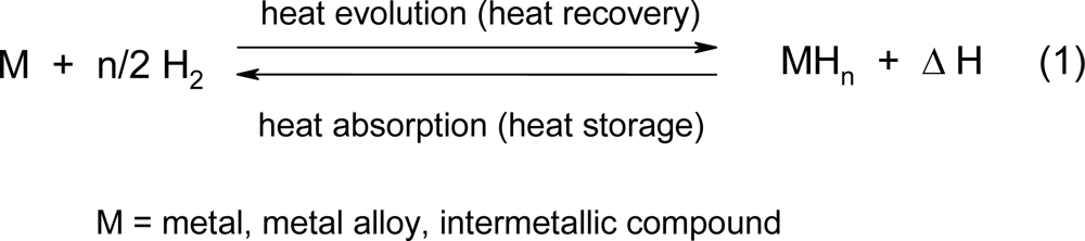
), then the metal hydride can by a heat supply upon decomposition into the metal and hydrogen. Upon thermal dissociation of a metal hydride by heat absorption (Equation 1, from right to left), the thermal energy is transformed into chemical energy. Expressed in another way: thermal energy can be reversibly stored as the heat of reaction of reversible chemical reactions. Among the methods for heat storage, sensible and thermochemical heat storage, the thermochemical method offers in general the higher amount of energy stored per mass of storage material (Table 1) [1, 2].
The special feature of metal hydrides as reversible heat storage systems is that upon their thermal dissociation the liberated hydrogen is simultaneously a fuel with the highest known gravimetric energy density (usually expressed in MJ·kg−1). The gravimetric energy density of hydrogen [1, 3] is about three times higher than that of gasoline. Hydrogen in liquid form is therefore used as a rocket fuel. A further remarkable feature of hydrogen as a fuel is that upon its combustion at high temperatures in air [4] as well as upon “cold combustion” in low temperature fuel cells, only pure water is produced. Thus, from ecological standpoint hydrogen is an ideally clean, albeit a secondary energy carrier. The last attribute means that hydrogen has first to be produced under consumption of primary energy sources which are at present primarily fossile fuels or, otherwise, nuclear energy (via water electrolysis) or, in the future, the expected solar energy. From the above statements it follows that the reversible metal hydride/metal systems (Equation 1 ) are to be considered as energy carriers in a double sense - namely as heat and as hydrogen storage systems.
Ijms 10 00325e1
In the heat storage application, the heat of reaction liberated in the hydride formation process serves as useful heat. Thereby hydrogen is confined in a closed system and is preserved during a great number of heat storage cycles. In the other case – as a hydrogen store – the hydrogen liberated from the hydride is present in an open system, and after displacement from the hydride it is irreversibly burned to water.

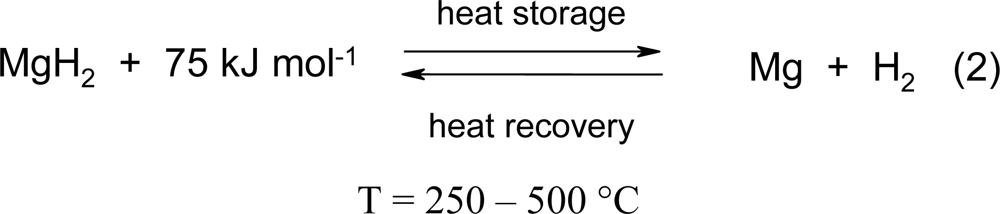
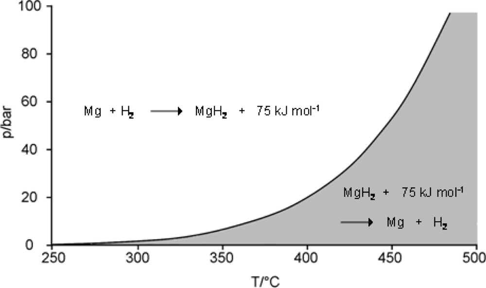
2. The principle of heat and hydrogen storage by the MgH2/Mg system

The magnesium hydride/magnesium system is particularly suitable for both purposes, because in MgH2 the reversible hydrogen storage capacity is the highest among reversible binary hydrides (7.6 wt.%) and because upon the reaction of magnesium with hydrogen (Equation 2 ) a relatively large amount of heat (75 kJ·mol−1 H2, (0.9 kWh kg-1Mg) at a temperature level between 200 and 500 °C is set free. Herewith an extremely important region for heat storage becomes available, since according to the Carnot principle, heat energy at this level can be transformed with high efficiency into other energy forms like mechanical energy and hence in electricity. We are dealing here mainly with the application of magnesium hydride as a heat storage medium. The MgH2/Mg system (Equation 2), however, can also be applied for hydrogen storage. Upon gradually heating up of MgH2 in a closed system the compound will dissociate giving Mg and H2 and the hydrogen pressure above the remaining MgH2 will increase exponentially following the van’t Hoff law (Figure 1).
Ijms 10 00325e2
The knowledge of the H2 dissociation (equilibrium) pressure as a function of temperature is of fundamental importance for the operation of the MgH2 heat and hydrogen storage system. At a given H2 pressure the course of the curve in Figure 1 determines which minimal temperature that is definitely necessary in order to liberate the hydrogen from MgH2 under a given H2 pressure (f.i. 450 °C for 40 bar of H2 pressure); and conversely, upon charging of Mg with hydrogen under given pressure conditions the temperature of the store will correspond to the hydrogen charging pressure. Thus, by choice of the hydrogen pressure it is possible to determine at which temperature level the stored heat will be delivered. The diagram in the Figure 1 shows additionally under which temperature and pressure conditions the system will absorb or desorb heat (shaded part - heat absorption; clear part - heat desorption). Although the diagram in the Figure 1 indicates under which conditions the reaction can go in one or in the other direction, it does not give any information if at all and how rapidly the reaction will take place. In the early [5] and in the more recent literature [6] it is often stated that the reaction of magnesium with hydrogen is notoriously sluggish and therefore hardly useful for heat storage [5]. For an optimal thermochemical heat storage material it is required that the chemical reaction be much more rapid than the rate of heat transport, so that the dynamics of the system will depend mainly on the rate of the heat transport. Additionally, it is required that the reaction in both directions is any times repeatable and that the material shows no sign of fatigue. For accelleration of chemical reactions, apart from increase of temperature, and the effect of the microstructure of particles [6], the general answer is catalysis.
At the beginning of our research work on metal hydrides there was the experimental finding that the reaction of magnesium with hydrogen in solution can be catalyzed [7]. During the past years the research in this field has led to MgH2/Mg materials which fulfill the above mentioned criteria: satisfactory kinetics combined with stability upon cyclic hydrogen charging and discharging. The first method for the preparation of the so-called “active MgH2/Mg materials” (Equation 3) [1, 8] consists in treatment of commercial Mg powder (f.i. 270 mesh) with hydrogen in an organic solvent (i.e. toluene) in the presence of a small amount of the soluble organometallic nickel complex bis(cyclooctadiene-1,5-Ni(0) [9] at ambient temperature and normal pressure. The Ni-complex is hereby instantaneously hydrogenated to cyclooctane and metallic nickel and the latter, in a fine dispersion, is precipitated on the surface of the Mg particles and acts as a catalyst for hydrogenation and dehydrogenation of the former. The second method [8] consists of intimately mixing of the Mg powder with 4–10 wt.% of fine commercial Ni powder. The activity of the material prepared according to the second method is somewhat lower than that of the first method. Cycle stability of the “standard materials” is presented in Ref. [8] (Figures 4, 5 and 9 therein). The Mg powders doped with Ni in these ways and fabricated several times on a 10 kg scale were shown in numerous tests to be suitable materials for heat and hydrogen storage and were employed by us and by others in several storage installation prototypes [1, 8, 1012], three of which are presented in Section 3. Already after the first hydrogenation the materials are fully active and remain active during hundreds of hydrogen charging-discharging cycles. A more recent 1,000 cycle test using both materials is shown in Figure 2 [13]. Some restrictions at high temperatures are discussed further in Section 4.
Ijms 10 00325e3
As already mentioned (Equation 2), hydrogen is liberated in the endothermic process of feeding heat (75 kJ mol−1 Mg) to MgH2, which until the reverse process of heat recovery must be temporarily stored. A heat storage system based on MgH2-Mg (Figure 3) has to be constructed as a closed system consisting of a MgH2 pressure container and an additional pressure container for the temporary storage of the displaced hydrogen (Part A). As schematically represented (Figure 3, Part A), the magnesium hydride container can be designed so to be much smaller than the pressure container for gaseous hydrogen, because of the much higher hydrogen concentration in the form of magnesium hydride. In the form of MgH2 hydrogen attains a concentration corresponding to a hydrogen pressure of 700 – 800 bar. Up to ~150 °C MgH2 has only a very low dissociation pressure, which means that hydrogen storage in this form is comparably a secure form for hydrogen storage.
In comparison to the first version (Figure 3, Part A), a much more compact construction can and has been realized, when for the temporary storage of hydrogen in place of a pressure container is applied an at low temperature hydrogen absorbing alloy (Figure 3, Part B) which with hydrogen forms a so-called low temperature (LT) metal hydride. A LT hydride is typically a hydride on Fe-Ti or La-Ni-basis [14] or, in future possibly on alanate basis [15].
Using LT hydrides for temporary storage of hydrogen, hydrogen is available at ambient or even below ambient tremperature. Apart from the compact construction, such a heat store (Figure 3, Part B) includes possibilities which are of great importance for the rational use of solar and other energy sources:
  • - absorption of hydrogen by the LT-alloy produces LT-heat (f.i. 30–70 °C) which is typically ≈ 1/3 of the MgH2 heat amount (75 kJ mol−1); this waste heat can be used for example for warm water supply;
  • - the desorption of hydrogen from the side of the LT hydride takes place with withdrawal of heat from the surroundings, that is with production of cold, that can be used for production of ice or for climatisation.
  • - altogether a closed circular system of two (or more) conjoined reversible metal hydride systems which operate at different temperature levels represent a so-called hydride chemical heat pump, which is applicable for different types of heat and energy transformations [16].

3. Experimental results concerning the MgH2-Mg system

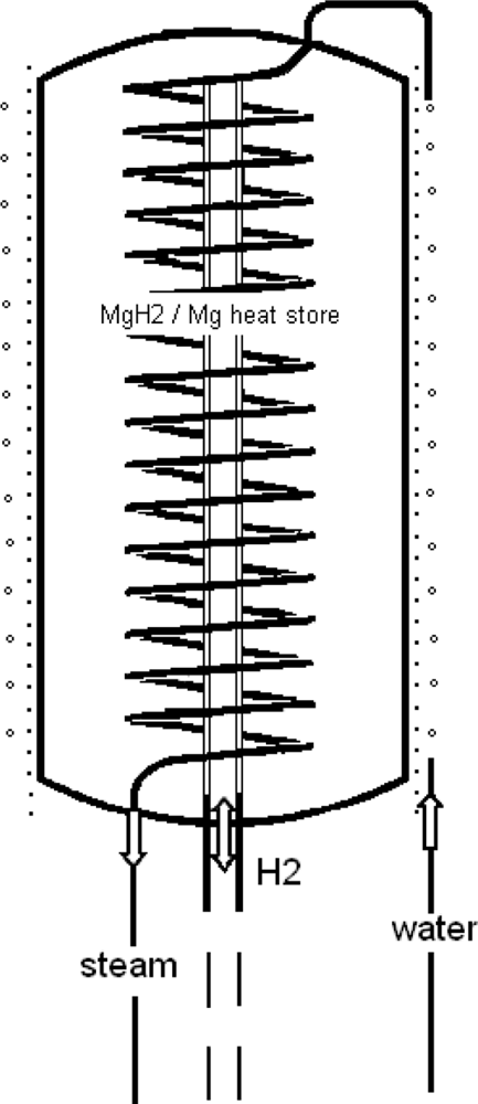
3.1. A process steam generator [17, 18]

In the following three installations which are designed for different fields of application and which have been realized as laboratory prototypes are described. These were primarily engineering tasks which were tackled at first by engineers by mathematical modelling (simulations) and calculations.
Unlike engineers, chemists prefer an experimental approach. In this sense the first experimental heat accumulator on magnesium hydride basis was built and tested in our institute. The facility for the production of the process steam was installed in the pilot plant of the institute and was in operation during 1½ years. In this connection the heat transfer problems within the hydride bed (heat pipe effect) was also investigated. The process steam generator is schematically represented in Figure 4, the isolated cylindric steel pressure vessel is filled with 14.5 kg of Ni-doped Mg-powder.
In the center of the vessel is installed a sintered metal tube for supply and removal of hydrogen. Around the vessel is wound a steel tube which is connected to a source for pressurized water. The tube is further lead into the inner of the vessel where it is helically embedded in the MgH2/Mg bulk. Hydrogenation of the Ni-doped storage material is carried out directly in the pressure vessel. For heat desorption the pressure vessel is electrically heated from outside, resulting in MgH2 dissociation. The hydrogen which escapes is temporary stored in a bunch of six commercial hydrogen pressure containers. As soon as the heating is interrupted and the temperature of the heat accumulator begins to decrease the hydrogen flows back from the pressure containers to the Mg/MgH2 vessel where the HT heat is regenerated and produces in the spiral tube superheated water vapor. Some technical data about the heat store unit are given in the Table 2.
The heat accumulator had the ability to produce 4 kW of heat, up to 90% capacity at the same temperature level. A coupled unit of a MgH2/Mg heat store with a hydrogen pressure container (Figure 3, Part A) can also serve as a heat buffer for intermittent HT heat sources.

3.2. A model of a thermochemical solar power plant [1, 8, 11, 13, 19, 20]

The MgH2/Mg-heat accumulator, first used to demonstrate the feasibility for production of “process vapor”, is clearly applicable for storage of industrial heat and at this temperature level (350–450 °C) of solar heat in particular. According to the “solar concept”, the combination of a solar-thermal power generator with a thermochemical MgH2 heat accumulator should enable generation of power also in the absence of sunshine, that is after sundown and during the passage of clouds. Within the frame of a publicly sponsored joint project between the both Max-Planck-Institutes in Mülheim, the IKE Institute of the Stuttgart University and the HTC Solar Company in Lörrach a first model of a small solar power station was built. Figure 5 shows a cross section of the installation. The main components were a “fixed focus concentrator” for solar radiation [11], a cavity radiation receiver, a heat pipe system for heat transfer, a Stirling engine, a MgH2 store, a hydrogen pressure or LT hydride store. For supply of the whole installation with solar heat a solar mirror collector with 6.5 m² area of a light weight type construction was built. The concentrated solar heat is used to drive the Stirling engine and produce power. Simultaneously, a more or less part of the solar heat is absorbed by the MgH2 heat store and the released hydrogen streams in the pressure container or, alternatively, in the LT hydride store. In periods without or weak solar irradiation the MgH2/Mg system cools down and the hydrogen flows back to the MgH2 store and produces there high temperature heat and via Stirling engine electric power. The model of the solar power plant was tested under laboratory [10] and in limited extent also under solar test field conditions [11] and in this way the ability of the system to function was established. Shortcomings of the installation were realized and the measures to address them proposed.

3.3. A solar cooking- and cooling-device [12, 19]

As a third example for the magnesium hydride application for heat storage and transformation a laboratory model of a solar cooking-and-cooling device was built. The device consists of a MgH2-heat store unit filled with 4.4 kg (~3 KWh heat) of the Ni-doped Mg-material and equipped with a cooking plate. The unit is linked to a LT metal hydride store unit with ~30 kg of a LT metall alloy (MmNi4.22Fe0.78) coupled to a refrigerator and a water reservoir. As a cooling cabinet a commercial ice-box of 113 L capacity is used. The solar mirror in this case has an area of 2.5 m2 and is made out of a fibrous plastic material.
During solar irradiation hours solar heat is concentrated by means of the fixed-focus concentrator and directly used for cooking. Simultaneously, hydrogen from the MgH2-store is desorbed and absorbed in the LT alloy, thus performing the task of heat storage. The LT heat of 30–40 °C is absorbed by a water reservoir. In order to be able to cook in the absence of solar irradiation the hydrogen is allowed to stream in the reverse direction, so that the heat of MgH2 formation provides heat for cooking. During the hydrogen desorption from the LT hydride, the desorption heat is removed from the surroundings and the resulting cold with the help of a water-glycol circle system is transferred to the ice-box in which ice is produced.
A complete cycle of an experimentally performed cooking- and cooling process is described in the following. At the beginning of such a cycle hydrogen is located in the LT hydride store. Upon opening of the valve between the two stores, the hydrogen streams to the HT-store resulting in a heat evolution of around 300 °C which remains during 5–6 h at this level and is usable for cooking. At the same time the LTH store itself cools down to -10 °C; ice is formed in the ice-box and the temperature there remains at about 0 °C. In this time 0.9 KWh of cold are produced and 35% of this amount are allotted for the production of ice. After a rest of 7 h during the night, during which the hydrogen supply is disconnected, through solar irradiation, at 350–450 °C, hydrogen is displaced from MgH2 and absorbed in the LT alloy with formation of warm water (30–40 °C). The device is now ready for a new cooking-cooling cycle. Laboratory tests were satisfactory, but solar (field) tests have not yet been done. As operational areas can be envisaged regions with a lot of sunshine but without energy infrastructure. Without any consumption of fuels or electric power it should be possible to cook and to refrigerate food at any day or night time.

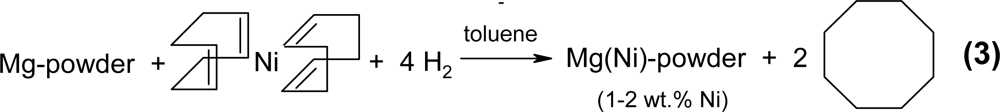
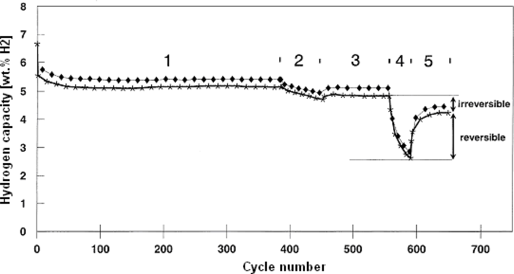
4. Ni-doped versus undoped MgH2-Mg materials for high temperature heat or hydrogen storage [21]

The design and construction of the above described appliances for energy and heat storage on MgH2/Mg basis are more or less tasks for engineers. For chemists there still remains the challenge of improving the properties of metal hydride storage materials and to develop new ones. So, for instance, the question arises which is the highest application temperature level for functioning of MgH2/Mg heat storage system. The question is of great importance, because according to the Carnot principle the efficiency of heat engines – be they small Stirling engines or steam turbines – increases with the temperature level of the fed heat. In order to remain with our example: the process steam of 500 °C is more efficient for the production of power than the same heat quantity at 400 °C or lower. If under this aspect we look again at temperature dependence of the MgH2 dissociation pressure (Figure 1), it can be seen that at the temperature of, f.i. 500 °C, the hydrogen pressure in the system is around 100 bar. Results of a 650 cycle test with mechanically Ni-doped Mg-powder (4 wt.%) under severe conditions are shown in Figure 6 [21].
Under a high dehydrogenation temperature (section 2, 480 °C) the hydrogen capacity and with it, the amount of stored heat, decreases. An investigation of this phenomenon showed that a part of these capacity losses can be recovered under milder conditions (Sections 2/3, 4/5, “reversible capacity losses”). A part of the capacity losses, however, is permanent (Sections 1/3, 3/5, “irreversible capacity losses”). Additionally, it could be shown that capacity losses upon cyclisation are higher with Ni-doped material than with undoped Mg-powder. The consequence is therefore that for heat storage at a high temperature level (> ~440 °C), it is of advantage to use plain Mg-powder in place of a Ni-doped one. The cause for this fall-off in performance at higher temperatures, as we presently know it, is a morphological one – namely the sintering of Mg particles at temperatures above 450 °C, which is more pronounced in a two (Mg-Ni) than in an one component system (Mg) [21].

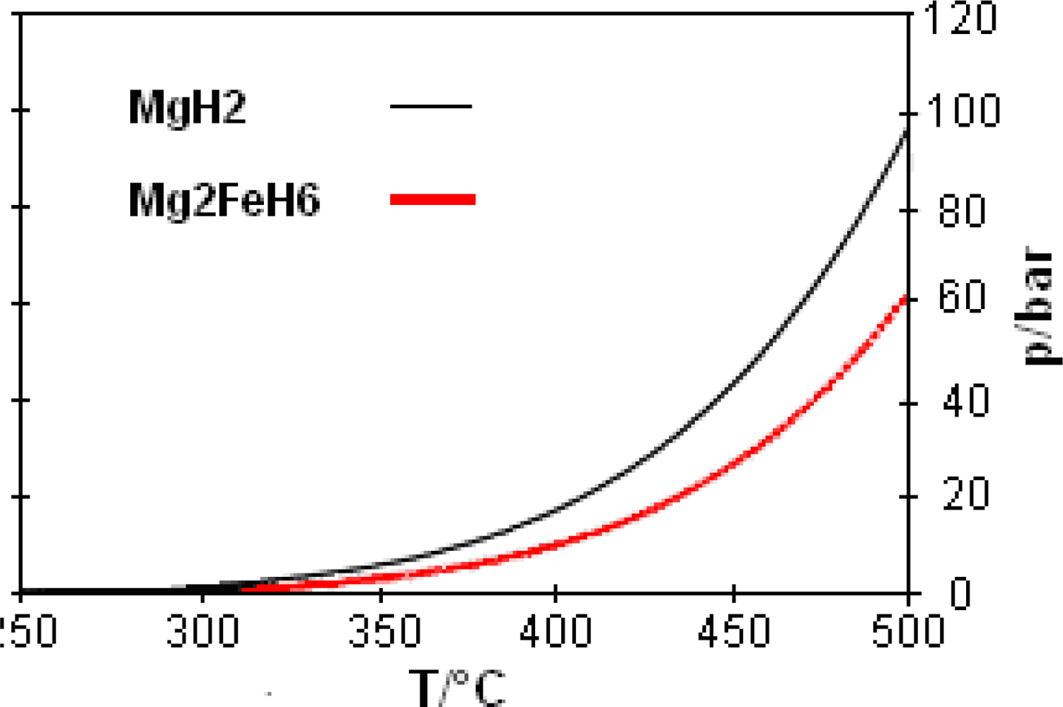
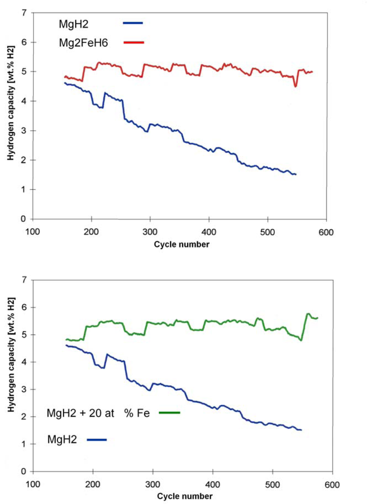
5. The Mg-Fe-H system and its potential for thermochemical thermal energy storage [22]

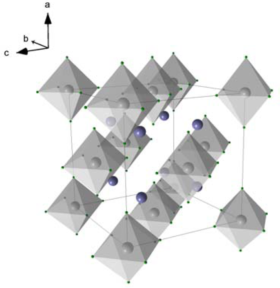
5.1. Mg2FeH6 as reversible ternary hydride system

A way out of the dilemma discussed in Section 4 was to look for alternative metal hydride/metal systems in which such sintering phenomena do not occur. To overcome this problem magnesium iron hydride Mg2FeH6 can be used for heat storage. The compound was discovered and the structure elucidated in 1984 by Yvon et al. after heating of 2:1 mixtures of 2 Mg and Fe powders at 450 °C under 20–120 bar H2 pressure [23].
As it can be seen in Figure 7, Mg2FeH6 is composed of Mg2+ cations and FeH64- anions in the form of octahedrons. In the center of the octahedrons is located a Fe atom, which is surrounded by six covalently bound H atoms. Alternatively to the high pressure method, Mg2FeH6 can be synthesized by reactive mechanical alloying of Fe and Mg elemental powders in a hydrogen atmosphere at room temperature [2426]. The gravimetric hydrogen content of Mg2FeH6 is 5.5 wt.%. The volumetric hydrogen density reaches 150 kg m−3 which is double of the density of liquid hydrogen (70 kg m−3). The advantage of Mg2FeH6 as a heat storage material in comparison to MgH2 (Table 3) is its higher stability and hence a lower hydrogen dissociation pressure (Figure 8). So, for example, the dissociation pressure of Mg2FeH6 at 500 °C (66 bar) - is about 1/3 lower than that of MgH2 at the same temperature (100 bar). This gives for the construction of pressure containers for Mg2FeH6 an advantage versus containers for MgH2.
Numerous cycle tests done with the Mg-Fe-H system prove that the system is superior under high temperature and pressure conditions with respect to cycle stability in comparison to the pure MgH2-Mg system (Figure 9, top) [22]. While the latter system under different HT conditions already looses capacity after 200–250 cycles (due to sintering), the Mg-Fe-H-systems, under comparable conditions, show no signs of loss of capacity and reaction rates even after 600 or more cycles. Even under very severe conditions (510–590 °C/138–149 bar) cycle stabilities with a capacity of more than 5 wt.% H2 are achieved. Interestingly, the improved cycle stability has been shown to exist also using less than stoichiometric amounts of Fe with respect to Mg (Figure 9, bottom). In view of the possible technical application of these systems for heat storage in future especially of solar heat in the temperature region around 500 °C or higher, this finding appears to be of importance [22]. However, further investigation of cycling properties of the mixed MgH2/Mg – Mg2FeH6/2Mg Fe hydride sytems is necessary.

5.2. Electron microscopy investigations of the Mg2FeH6 materials

The cause for the improvement of thermochemical storage properties of the Mg-Fe-H system with respect to the MgH2 system could be partially elucidated via electron microscopy investigations on Mg-Fe-H samples in the hydrogenated and dehydrogenated state. Raster electron- microscopy images of the starting Fe and Mg powders (Fe 5–10 μm and Mg particles 50–100 μm) and of Mg2FeH6 after 600 hydrogenation/dehydrogenation cycles at high temperatures are shown in Figures 10a–c. A high resolution transmission electron microscopy (TEM) micrograph of Mg2FeH6 is reproduced in Figure 11 (top). At 1:500,000 magnification one can already perceive the atomic net plains of the crystalline magnesium-iron hydride. The material is perfectly homogeneous. On the lower part of the Figure (Figure 11, bottom) can be seen a TEM photo of the dehydrogenated material: in this case black and colorless regions can be discerned. By energy dispersive X-ray (EDX) analyses it could be proved that the black regions are almost pure iron and the colorless transparent ones are pure magnesium. Upon each dehydrogenation the two metals separate from each other.
The size of the regions are in the range of 20–50 nm. Apparently, due to this extremely fine dispersion it is possible that after each hydrogenation step the homogeneous Mg2FeH6 phase is formed. In the hydrogenation step a transfer of (probably) magnesium atoms must take place. With the help of TEM it was possible to identify different stages of Mg2FeH6 formation from Fe, Mg and H2 and which takes place on the surface of Fe grains (Figure 11); for details see Ref. [22]. It appears plausible that this special circumstance - the separation of metals in two immiscible phases upon dehydrogenation and the merging to one phase upon hydrogenation - counteracts agglomeration of particles and thus, is one of the probable causes of cyclic stability.

6. A picture of a thermochemical storage of solar heat on the MgH2/Mg basis

6.1. Comparision of the MgH2/Mg system with the existing heat storage system of Andasol 1

Andasol 1 is a solar thermal power plant located in Andalucia (Spain) with a 50 MW steam turbine for electricity production. To run the plant during the dark a heat storage system is installed for additional 7.5 h electricity production at night. The storage system consists of two insulated storage tanks each 14 m high and 36 m in diameter (Figure 12). They are filled with 28,000 tons of a molten salt mixture of sodium and potassium nitrate. The tanks are kept at different temperatures, the cold tank at 260 °C and the hot tank at 390 °C. To charge heat, the “cold” molten salt picks up heat in a heat exchanger from the 400 °C hot oil of the solar field and stores in the hot tank. For discharging the process is reversed [27]. The overall storable heat amount in this system is 1,000 MWh [28].
As mentioned in Section 2 the amount of heat released upon reaction of 1 kg of Mg with H2 is 0.9 kWh. Thus it can be roughly estimated that an amount of about 1,100 tons of Mg-metal would be able to store the same amount of heat as the Andasol storage system. In addition to the storage of the Mg/MgH2 mixture, a second container is necessary for the temporary storage of the hydrogen released during the dissociation of MgH2 (heat absorption Figure 3, Part A). The most simple option is the storage of hydrogen gas under own dissociation pressure of MgH2. As an example we assume here working temperatures of the heat storage between 370 and 400 °C. At 370 °C the dissociation pressure of MgH2 is 10 bar and at 400 °C roughly 20 bar (Figure 1) [29]. In this pressure and temperature ranges, a simple calculation shows [30], a volume of 109,000 m3 of H2 gas resulting from decomposition of MgH2 must be stored. This sounds a lot, but, as shown below, gas storage of this order of magnitude has been standard gas technology for more than hundred years.

6.2. Options for the storage of large volumes of hydrogen gas

6.2.1. Hydrogen gas storage in containers

Natural gas storage under elevated pressures in spherical gas tanks is a widely used method. A system with a diameter up to 40 m and a maximum gas pressure of roughly 10 bar for natural gas has been constructed in Wuppertal, Germany and is in use since the 1950’s. The volume of this storage vessel is 55,000 m3. Pipe containers are another simple method for the storage of natural gas up to pressures of 100 bar. A similar construction can also be used for the storage of hydrogen.

6.2.2. Hydrogen storage in gas pipelines

Large volumes of H2 can be stored in existing hydrogen pipelines. A hydrogen pipeline can possibly be situated near a thermal solar power plant.

6.2.3. Hydrogen gas storage in geological formations

The storage of natural gas in underground salt caverns is also a widely used method to overcome fluctations in the demand for the gas [31]. Recently, several studies have shown that underground caverns can be used for the storage of hydrogen under elevated pressures and with extremely low leak rates [32, 33]. Underground hydrogen storage in salt caverns is situated, f.i. in Teesside, Great Britain. The salt caverns are in a depth of 350 m with an overall volume of 70,000 m3. The hydrogen gas is under a constant pressure of 45 bar, which is the result of brine replacement. These values are close to those of a conceptual storage system based on a MgH2/Mg storage system for a 50 MW solar thermal power plant. On condition is that a suitable geological formation can be found close to the power plant, but underground hydrogen storage option appears to be a cheap and simple storage method for hydrogen released from MgH2.

7. Conclusions

In the face of todays’ urgent climate, energy and economical problems we are at present witnessing intensified planning and building of thermal solar power plants [34]. To enable the plants to function overnight storage of HT heat is necessary, which in practice usually involves storage of sensible heat by means of molten salts. As chemists we propose that, as presented in Section 6, the “thermochemical option” based on HT metal hydrides should also be taken into consideration.
On the basis of the present short overview one can easily recognize that in the research field of metal hydrides as energy storage systems both at high and low temperatures there remains yet a lot to be discovered. Currently the search for low temperature reversible hydride systems with higher than at present known H2 storage capacity, as required for heat pumps and production of cold, but first and foremost as hydrogen storage materials for fuel-cell driven cars [15, 35], seems especially worthy of efforts at the moment.

Acknowledgments

The assistance and intellectual input from B. Spliethoff and K. Schlichte over several years of research is gratefully acknowledged!

References and Notes

  1. Bogdanović, B; Ritter, A; Spliethoff, B. Active MgH2-Mg systems for reversible chemical energy storage. Angew. Chem. Int. Ed 1990, 29, 223–234. [Google Scholar]
  2. Beckmann, G; Gilli, PV. Thermal Energy Storage; Springer-Verlag: Wien, New York, 1984; p. 57, Table 2.4. [Google Scholar]
  3. Buchner, H. Energiespeicherung in Metallhydriden; Springer Verlag: Wien, New York, 1982. [Google Scholar]
  4. The formation of NOx in application of H2 for engines with internal combustion can be practically eliminated using lean gas mixtures (λ λ 2); taken from [3], p. 126.
  5. Rummel, W. Heat storage in magnesium-hydrogen system. Siemens Forsch. Entwicklungsber 1978, 7, 44. [Google Scholar]
  6. Zaluska, A; Zaluski, B; Ström-Olsen, JO. Nanocrystalline magnesium for hydrogen storage. J. Alloys Comp 1999, 288, 217–225. [Google Scholar]
  7. Bogdanović, B; Liao, S; Schwickardi, M; Sikorsky, P; Spliethoff, B. Catalytic synthesis of magnesium hydride under mild conditions. Angew. Chem. Int. Ed. Engl 1980, 19, 818–819. [Google Scholar]
  8. Bogdanović, B; Hartwig, Th; Spliethoff, B. The development, testing and optimization of energy storage materials based on the MgH2-Mg system. Int. J. Hydrogen Energy 1993, 18, 575–589. [Google Scholar]
  9. Bogdanović, B; Kröner, M; Wilke, G. Olefin-Komplexe des Nickels (0). Liebigs Ann. Chem 1966, 699, 1–23. [Google Scholar]
  10. Wierse, M; Groll, M. Development, construction and testing of a thermo-chemical energy store on the MgH2 basis for solar power plants and other energy supplying systems (in German), a joint project of the German BMFT, 0328939 B, 1995; Wierse, M.; Groll, M. System performance of a solar thermal power station with a thermochemical energy storage. Proceedings of the 11th Hydrogen Energy Conference, Stuttgart, Germany, 23-28/7/1996; Veziroglu, TN, Winter, CJ, Baselt, JP, Kreysa, G, Eds.; Dechema: Frankfurt, Germany, 1996; pp. 1997–2003. [Google Scholar]
  11. Kleinwächter, J; Mitzel, M. dto., a joint project of the German BMFT, 0328993 A. 1996.
  12. Steiner, D; Wierse, M; Groll, M. Development of a solar cooking/cooling unit with a thermochemical energy store based on metal hydrides. Proceedings of the 11th Hydrogen Energy Conference, Stuttgart, Germany, 23-28/7/1996; Veziroglu, TN, Winter, CJ, Baselt, JP, Kreysa, G, Eds.; Dechema: Frankfurt, Germany, 1996; pp. 2005–2010. [Google Scholar]
  13. Reiser, A; Bogdanović, B; Schlichte, K. The application og Mg-based metal hydrides as heat energy storage systems. Int. J. Hydrogen Energy 2000, 25, 425–430. [Google Scholar]
  14. Bowman, RC; Fultz, B. Metallic hydrides I: Hydrogen storage and other gas-phase applications. MRS Bulletin 2002, 27, 688–693. [Google Scholar]
  15. Schüth, F; Bogdanović, B; Felderhoff, M. Light metal hydrides and complex hydrides for hydrogen storage. Chem. Commun 2004, 2249–2258. [Google Scholar]
  16. Dantzer, P. Metal-hydride technology: A critical review. In Hydrogen in Metals III, Topics in Applied Physics.; Wipf, H, Ed.; Springer-Verlag: Berlin, Heidelberg, Germany, 1997; Volume 73. [Google Scholar]
  17. Bogdanović, B; Ritter, A; Spliethoff, B; Straßburger, K. A process steam generator based on the high temperature magnesium hydride/magnesium heat storage system. Int. J. Hydrogen Energy 1995, 20, 811–822. [Google Scholar]
  18. Straßburger, K. Wärmetransformation und thermische Energiespeicherung durch das aktive MgH2/Mg-System; . Thesis, University Essen: Essen, Germany, 1999. [Google Scholar]
  19. Bogdanović, B; Spliethoff, B; Ritter, A. The magnesium hydride system for heat storage and cooling. Ztschr. Physik. Chem. Neue Folge 1989, 164, 1497–1508. [Google Scholar]
  20. Bogdanović, B; Ritter, A; Spliethoff, B; Straßburger, K. Development, optimisation and testing of energy storage materials on the magnesium hydride magnesium basis (in German), a joint project of the German Federal Ministry for Research and Technology (BMFT), 0328939 C. 1992.
  21. Bogdanović, B; Hofmann, H; Neuy, A; Reiser, A; Schlichte, K; Spliethoff, B; Wessel, S. Ni-doped versus undoped Mg-MgH2 materials for high temperature heat or hydrogen storage. J Alloys Compd 1999, 292, 57–71. [Google Scholar]
  22. Bogdanović, B; Reiser, A; Schlichte, K; Spliethoff, B; Tesche, B. Thermodynamics and dynamics of the Mg-Fe H system and its potential for thermochemical thermal energy storage. J. Alloys Comp 2002, 345, 77–89. [Google Scholar]
  23. Didisheim, JJ; Zolliker, P; Yvon, K; Fischer, P; Schefer, J; Gubelmann, M; Williams, AF. Dimagnesium Iron(II) Hydride, Mg2FeH6, Containing Octahedral FeH64- Anions. Inorg. Chem 1984, 23, 1953–1957. [Google Scholar]
  24. Huot, J; Boily, S; Akiba, E; Schulz, R. Direct synthesis of Mg2FeH6 by mechanical alloying. J. Alloys Compd 1998, 280, 306–309. [Google Scholar]
  25. Gennari, FC; Castro, FJ; Andrade Gamboa, JJ. Synthesis of Mg2FeH6 by reactive mechanical alloying: formation and decomposition properties. J. Alloys Compd 2002, 339, 261–267. [Google Scholar]
  26. Varin, RA; Li, S; Calka, A; Wexler, D. Formation and environmental stability of nanocrystalline and amorphous hydrides in the 2Mg-Fe mixture processed by controlled reactive mechanical alloying (CRMA). J. Alloys Compd 2004, 373, 270–286. [Google Scholar]
  27. Fairly, P. Largest Solar Thermal Power Plant to Start Up.
  28. .
  29. Bogdanović, B; Bohmhammel, K; Christ, B; Reiser, A; Schlichte, K; Vehlen, K; Wolf, U. Thermodynamic investigation of the magnesium hydrogen system. J. Alloys Compd 1999, 282, 84–92. [Google Scholar]
  30. The amount of 1,100 tons of Mg, when converted into MgH2, would upon dissociation deliver 1.09 × 10⁶ Nm3 of H2 or 109,000 m3 at 10 bar pressure. Thus, for temporary storage of hydrogen a storage tank of 109,000 m3 capacity is necessary. We envisage that at the beginning of a heat storage cycle the tank is filled with 10 bar of hydrogen. Upon heating of the storage unit filled with 1,100 tons of MgH2 from 370 to 400 °C, the unit, upon complete dissociation of MgH2 would release 109,000 m3 of hydrogen, which when introduced into the storage tank would result in a pressure increase from 10 to 20 bar (Figure 1). During night the heat store unit will cool down and the hydrogen will flow back to the heat store, producing there 1,000 MWh of heat at the 400 to 370 °C temperature level. The pressure in the system will drop from 20 to 10 bar, thus restoring the initial state. It should be mentioned that the described system is self-controlled, depending only of the amount of heat out- or input to the storing unit. Certainly, the presented is a very crude outline of a heat storage cycle, since during the cycle ubiquitous heat losses have to be taken into account. On the other hand, by assuming higher than at presently used working temperatures and pressures for the heat storage cycle, much smaller volumes for the hydrogen storage tank can be calculated.
  31. Sedlacek, R. Underground Gas Storage in Europe. Erdöl, Erdgas, Kohle 1999, 115, 537–540. [Google Scholar]
  32. Leighty, W. Running the world on renewables: Hydrogen transmission pipelines and firming geologic storage. Int. J. Energy Res 2008, 32, 408–426. [Google Scholar]
  33. Crotogino, F; Hamelmann, R. Wasserstoff-Speicherung in Salzkavernen zur Glättung des Windstromangebotes. 14. Symposium zur Nutzung regenerativer Energiequellen und Wasserstofftechnik, Stralsund, Germany, Nov. 2007. Energieperspektiven 2. 2008.
  34. .
  35. Züttel, A; Borgschulte, A; Schlapbach, L (Eds.) Hydrogen as a Future Energy Carrier; Wiley-VCH: Weinheim, Germany, 2008.
Figure 1. Dissociation pressure curve of MgH2.
Ijms 10 00325f1
Figure 2. 1000 cycle test of Ni-doped MgH2, time for a full cycle 3 h.
Ijms 10 00325f2
Figure 3. Schematical representation of construction of MgH2/Mg heat stores. Part A: temporary storage of hydrogen in a pressure container; part B: temporary storage of hydrogen in a low-temperature metal hydride.
Ijms 10 00325f3
Figure 4. The process steam generator based on MgH2 [17, 18].
Ijms 10 00325f4
Figure 5. Cross section of the model of the solar power station, with MgH2 heat storage units and fix-focus solar concentrator.
Ijms 10 00325f5
Figure 6. A 650 cycle test performed with mechanically Ni-doped (4 wt.%) 270 mesh Mg powder, demonstrating reversible and irreversible hydrogen capacity losses under severe conditions; —*— and —♦—, 45 and 135 min hydrogenation times, respectively [21].
Ijms 10 00325f6
Figure 7. Crystal unit cell of Mg2FeH6; Mg-atoms are shown in blue, Fe-atoms are located in the centers of the octahedrons.
Ijms 10 00325f7
Figure 8. Temperature dependence of the dissociation pressure of Mg2FeH6 in comparision with that of MgH2 [22].
Ijms 10 00325f8
Figure 9. Hydrogen storage capacity of MgH2, Mg2FeH6 (top) and of the mixed Mg2FeH6-MgH2 system [22]. (Conditions for re/dehydrogenations: 482/533 °C, 80/86 bar, 1.5/1.5 h).
Ijms 10 00325f9
Figure 10. Raster electron images from top to the bottom: a) Fe-metal, b) Mg-flakes, c) Mg2FeH6 after 600 cycles.
Ijms 10 00325f10
Figure 11. Left: HR-TEM-pictures of Mg2FeH6 (top) and dehydrogenated material (2Mg + Fe) (bottom); right: TEM micrographs of different steps of Mg2FeH6 formation are recorded. Dark regions of the particles are Fe regions and the lighter consist of Mg2FeH6. (a) Initial stage of the Mg2FeH6 formation; (b) vermicular excresence of Mg2FeH6 out of the surface of an iron seed; (c) final stage of the Mg2FeH6 formation [22].
Ijms 10 00325f11
Figure 12. 50 MW Solar power plant Andasol 1 with solar thermal energy storage system [27], photo with permission from Solar Millennium.
Ijms 10 00325f12
Table 1. Frequently used solid and liquid materials for the storage of sensible heat [1].
M.p. [°C]Temperature range [°C]ρ [g cm−3]c[kJ kg−1K−1]
Water00 – 1000.98 [a]4.19
Thermo-oil−70 / −10up to 350 [b]0.87 [a]2.1
53 KNO3/40 NaNO2/7 NaNO3 [c]142up to 4501.85 [a]1.3
Na980.84 [d]1.26
Cast iron1150 – 13007.2 [d]0.54
Aluminium6602.7 [d]0.92
Fire clay2.1–2.6 [d]1.0
Al2O317003.0 [d]1.0
MgO17003.0 [d]1.0
Stone1.9–2.6 [d]0.8–0.9
Concrete0.9
[a]verage density in the temperature range given,
[b]some thermooils can be used up to 390 °C,
[c]wt.%,
[d]at room temperature.
Table 2. Technical Data of the MgH2-Heat Store Unit [17, 18].
Amount of storage material (Ni-doped Mg)14.5 kg
Volume of the pressure vessel19.4 dm3
Weight of the pressure vessel26 kg
Bulk density0.75 g cm−3
Maximum operational pressure50 bar
Maximum operational temperature450 °C
Total weight40 kg
Amount of stored heat / total weight0.25 kWh kg−1
Maximum power output4 kW
Amount of water to be vaporized at the power output of 4 kW6 kg h−1
Maximum steam temperatureca. 400 °C
Maximum steam pressure40 bar
Table 3. Comparision of important values for heat storage using MgH2 and Mg2FeH6 [22].
MgH2Mg2FeH6
Reaction enthaply ΔH [kJ mol−1]7477.4
Hydrogen content calc. [wt.%]7.665.47
Hydrogen content expt. [wt.%]65
Theoretical density of the hydride [g cm−3]1.422.74
Experimentally realized density [g cm−3]0.81.22
Heat storage density (calc. weight) [kJ kg−1]2,8142,106
Heat storage density (expt. weight) [kJ kg−1]2,2041,921
Heat storage density (calc. volume) [kJ dm−3]3,9965,768
Heat storage density (expt. volume) [kJ dm−3]1,7632,344

