
A Hybrid Indoor Localization and Navigation System with Map Matching for Pedestrians Using Smartphones


Abstract
:1. Introduction
2. Related Works

| Sensors* | Technique* | Evaluation Scenario* | Max. Distance | Achieved Accuracy** | |
|---|---|---|---|---|---|
| [13] | Acc, Gyro | ZUPT, Map Matching | Waist mounted sensor node | 40 m | TTD, 98.26% |
| [14] | Acc, Gyro | Ramp detection | Foot mounted sensor node | 1000 m | ε/TTD, 0.15%–1.06% |
| [15] | Acc, Mag | PDR with Map Matching | In-pocket motion sensor | 104 m | Average LE, 0.55 m–0.93 m |
| [16] | Acc, Gyro, Mag | Neural network, EKF | Smartphone held in hand in front of body, outdoors | 400 m | SD, approx. 100%; TTD, 97.98%–102.67% ε/TTD, 0.85%–2% |
| [17] | Acc, Gyro | Quaternion complementary filter | Mobile device kept in jacket and trousers pocket, held in hand in front of body | 270 m | SD, above 98%; Median of TTD, 100.22% |
| [18] | Acc, Gyro, Mag | Map Matching, Mag and Gyro Fusion | Smartphone kept in pocket, held in hand while calling, swinging, in front of body | 600 m | Average LE, 0.45 m–0.74 m; 95th percentile of LE, 0.8 m–1.71 m |
| [19] | Acc, Gyro | Novel stride length estimator | Smartphone mounted on waist and kept in chest pocket | 6.69 m | TTD, 96.14%–97.35% |
| [20] | Acc, Gyro | Mode classification | Smartphone kept in trouser pocket, held in hand while swinging and in front of body | 96.33 m | SD, 95.49%; TTD, 99.7% |
| [21] | Acc, Gyro, Mag | Mag and Gyro Fusion | Smartphone held in hand in front of body | 168.55 m | Average LE, 1.35 m; Average HE, 2.28o |
| [22] | Acc, Gyro, BN | PDR with BN Ranging | Smartphone held in hand with BNs installed on ceiling | 90 m | Average LE, 0.88 m |
| [23] | Acc, Mag, BN | Estimating BN positions, PDR with BN Ranging | Smartphone held in hand with BNs deployed at arbitrary positions on floor | 480 m | Average LE, 1.59 m–5.46 m |
| [24] | Acc, Gyro, Wi-Fi | PDR with Wi-Fi RSSI fusion by Recursive Density Estimation | Smartphone held in hand with five Wi-Fi access points installed | 120 m | Average LE, less than 5.22 m |
| [25] | Acc, Gyro, Wi-Fi | PDR with Zigbee RSSI fusion by EKF | Waist mounted IMU and Zigbee node | 25 m | Maximum LE, 4 m |
| [26] | Acc, Gyro, NFC | PDR with NFC error correction | Smartphone held in hand in front of body with NFC tags on floor ground | 44 m | Maximum LE, 1.7 m |
| [27] | Acc, Gyro, Mag, RFID | PDR with RFID RSSI fusion by EKF | Foot mounted IMU with RFID tags installed in rooms | 1000 m | Average ε/TTD, 1.27% |
| [28] | Acc, Gyro | PDR with assistive QR code | Smartphone held in hand and scan QR code along the path | 35 m | LE, 0.64 m |
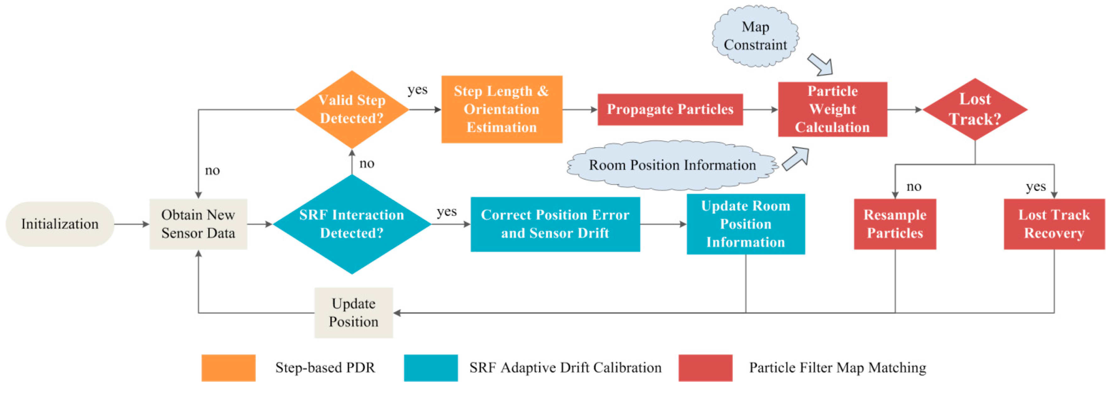
3. Proposed HILN System
3.1. System Overview


3.2. Step-Based PDR System
3.2.1. Step Detection

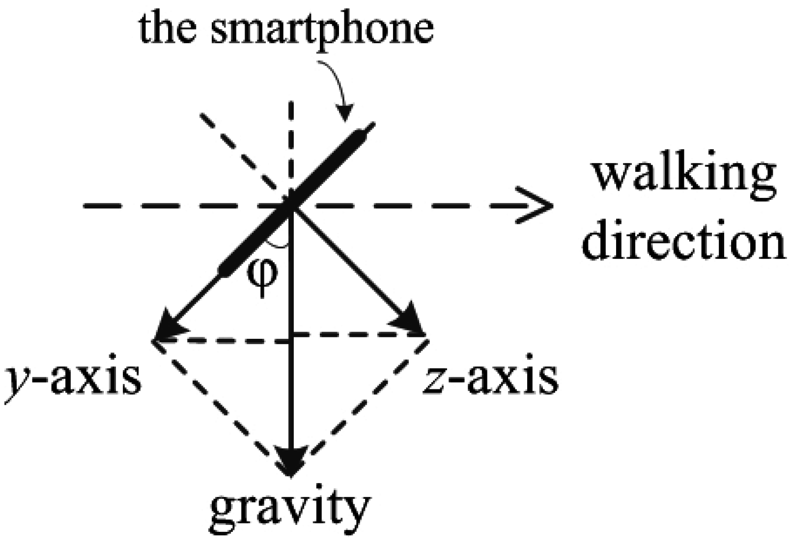
3.2.2. Step Length & Orientation Estimation
| Algorithm 1 Averaging Yaw Data in 180o Ambiguity |
|
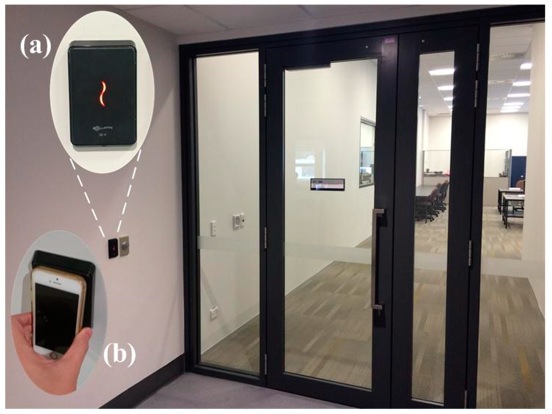
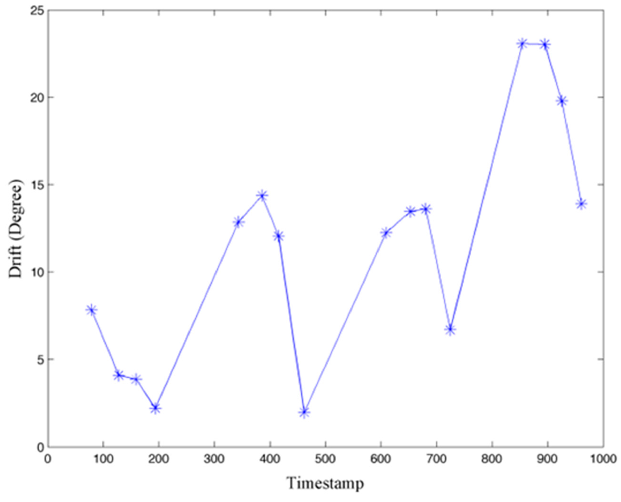
3.3. SRP Adaptive Drift Calibration


3.4. Particle Filter Map Matching

| Algorithm 2 Particle Filter Map Matching for Pedestrian Tracking |
| 1. Initialization: 2. Initial position , initialize particle set Particle0, 3. MAP is a set containing all valid positions in a map 4. POSRPI is a set containing all RPI {Corridor, Roomr (r = valid room number)} 5. TP is a set containing all turning point positions in corridor zone with a total number of M 6. at step index s+1: 7. get the estimated step length Ls and orientation from PDR subsystem 8. get current RPI , the current valid position set is selected based on posrpi 9. propagate particle set Particles to Particles+1, assign weight to each propagated particle 10. for i = 1 to N 11. draw a random number rand from N(0, σ2), = + rand 12. propagate particles to according to Equation (8) 13. assign particle weight 14. 15. end for 16. if all particle weights are zero 17. if equals Corridor and current position Ps is not in zones where lost track is allowed* 18. go to Lost Track Recovery 19. else 20. Ps+1 = Ps, Particles+1 = Particles 21. end if 22. else 23. , Resample particle set Particles+1 using Systematic Resampling 24. end if 25. end of processing at step index s+1 26. 27. Lost Track Recovery 28. Start: 29. select the turning point TPk , having the minimum distance to Ps in TP 30. if TPk is not unique 31. Ps = Ps-1, go to Start 32. else 33. Ps+1 = TPk, 34. end if |
4. Evaluation & Discussion
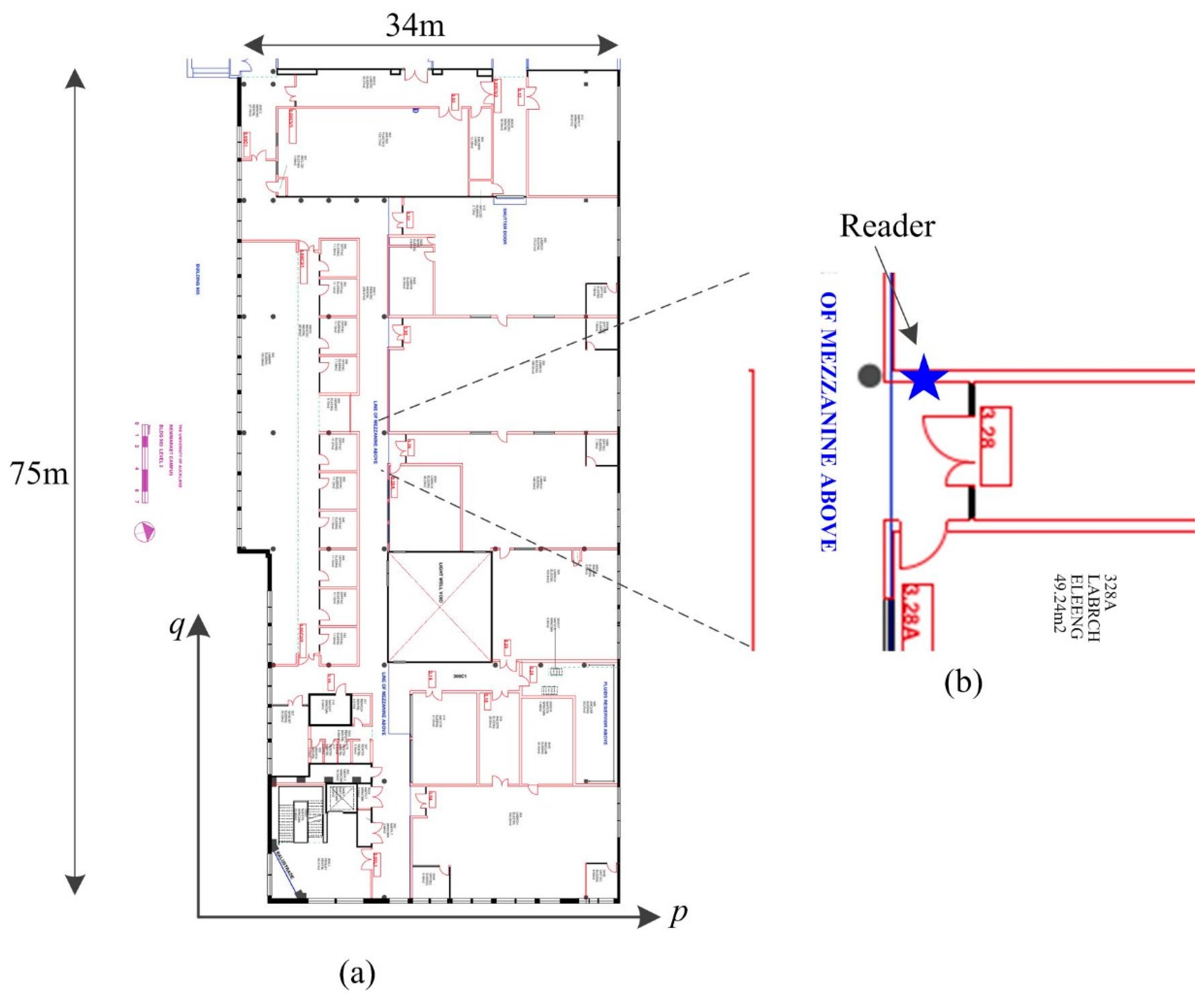
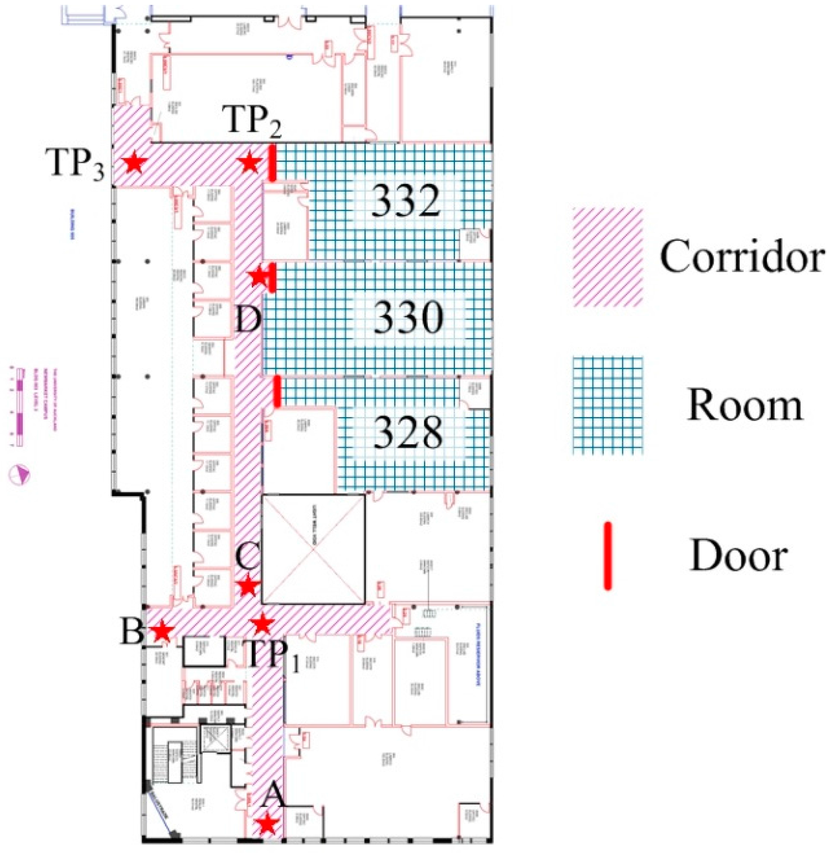
4.1. Experimental Setup

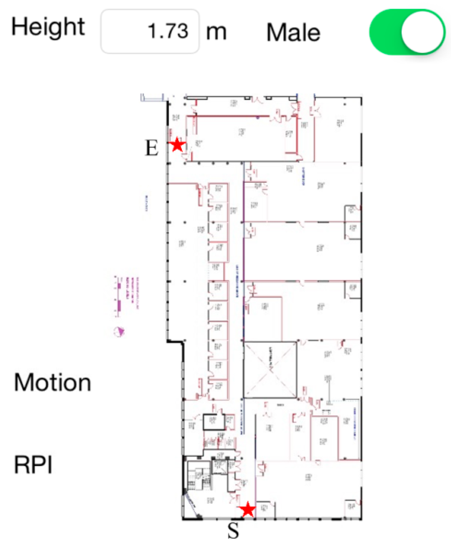
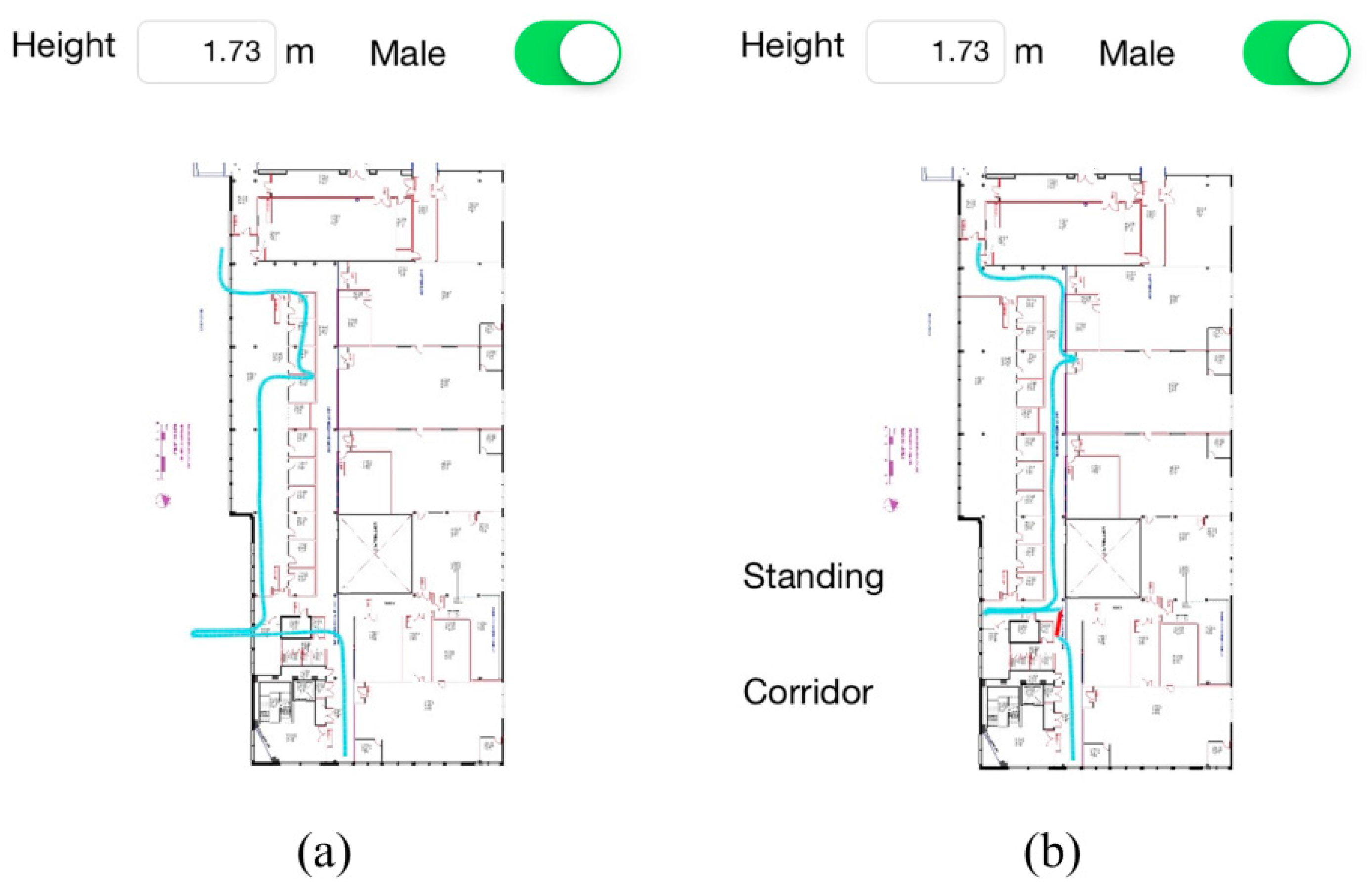
4.2. Short-Term Walking Experiments

| Actual Step Count | 273 | |
| Detected Step Count/Accuracy | 271/99.27% | |
| Travelled Distance (m) | 202.8 | |
| Estimated Total Travelled Distance (m)/Accuracy | 202.1/99.65% | |
| Position Error Corrected (m) | Entering Room 332 | 1.19 |
| Leaving Room 332 | 0.78 | |
| Gyroscope Yaw Drift Corrected (rad/deg) | Entering Room 332 | 0.011/0.63o |
| Leaving Room 332 | 0.033/1.89o | |
| Final Position Error ε (m) | 1.51 | |
| ε/TTD | 0.74% | |

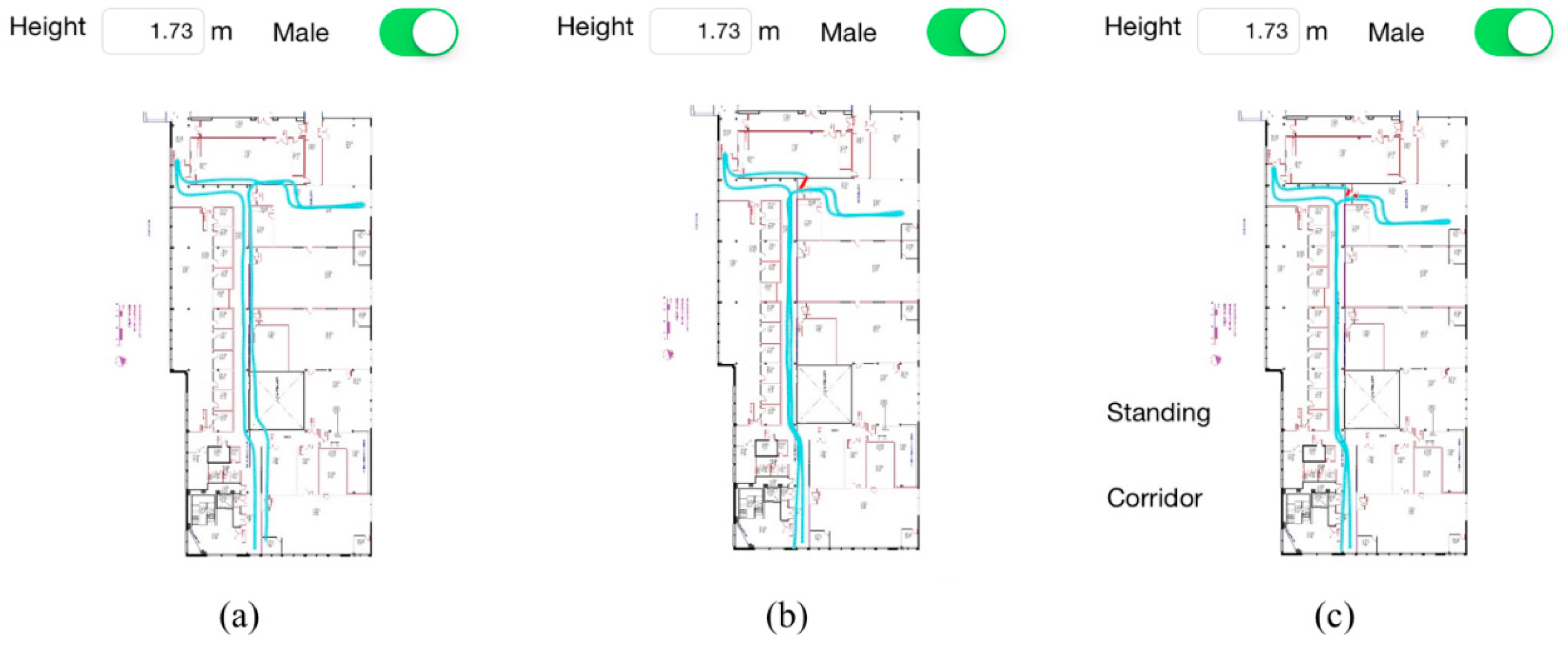
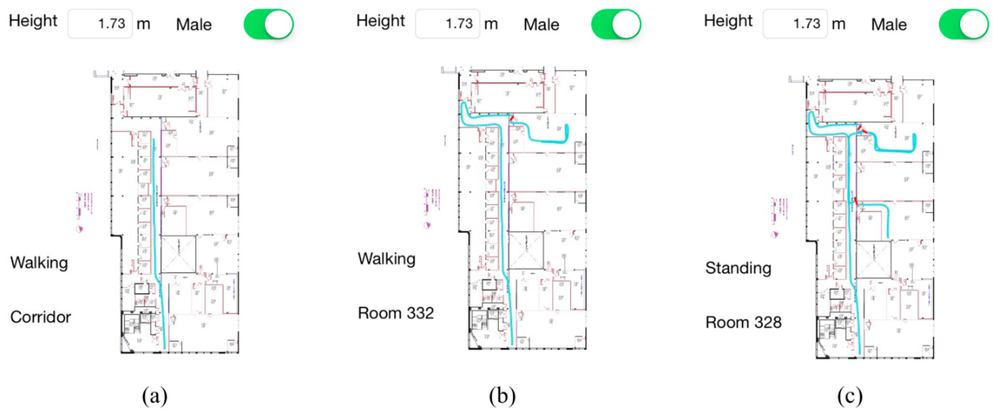
4.3. Long-Term Walking Experiment
| Actual Step Count | 1486 | ||||
| Detected Step Count/Accuracy | 1449/97.51% | ||||
| Total Travelled Distance (m) | 1083.95 | ||||
| Estimated Total Travelled Distance (m)/Accuracy | 1062.21/97.99% | ||||
| Position Error Corrected (m) | Entering Room 328 | 2.76 | 0.57 | 1.39 | 0.57 |
| Leaving Room 328 | 0.95 | 0.85 | 0.20 | 0.70 | |
| Entering Room 332 | 1.55 | 1.34 | 1.22 | 1.75 | |
| Leaving Room 332 | 1.68 | 1.56 | 1.29 | 1.31 | |
| Gyroscope Yaw Drift Calibrated (rad/deg) | Entering Room 328 | 0.068/3.90o | 0.210/12.04o | 0.238/13.64o | 0.345/19.78o |
| Leaving Room 328 | 0.039/2.24o | 0.034/1.95o | 0.117/6.71o | 0.242/13.87o | |
| Entering Room 332 | 0.137/7.85o | 0.224/12.84o | 0.214/12.27o | 0.402/23.04o | |
| Leaving Room 332 | 0.071/4.07o | 0.251/14.39o | 0.235/13.47o | 0.402/23.04o | |
| Final Position Error ε (m) | 1.36 | ||||
| ε/TTD | 0.13% | ||||


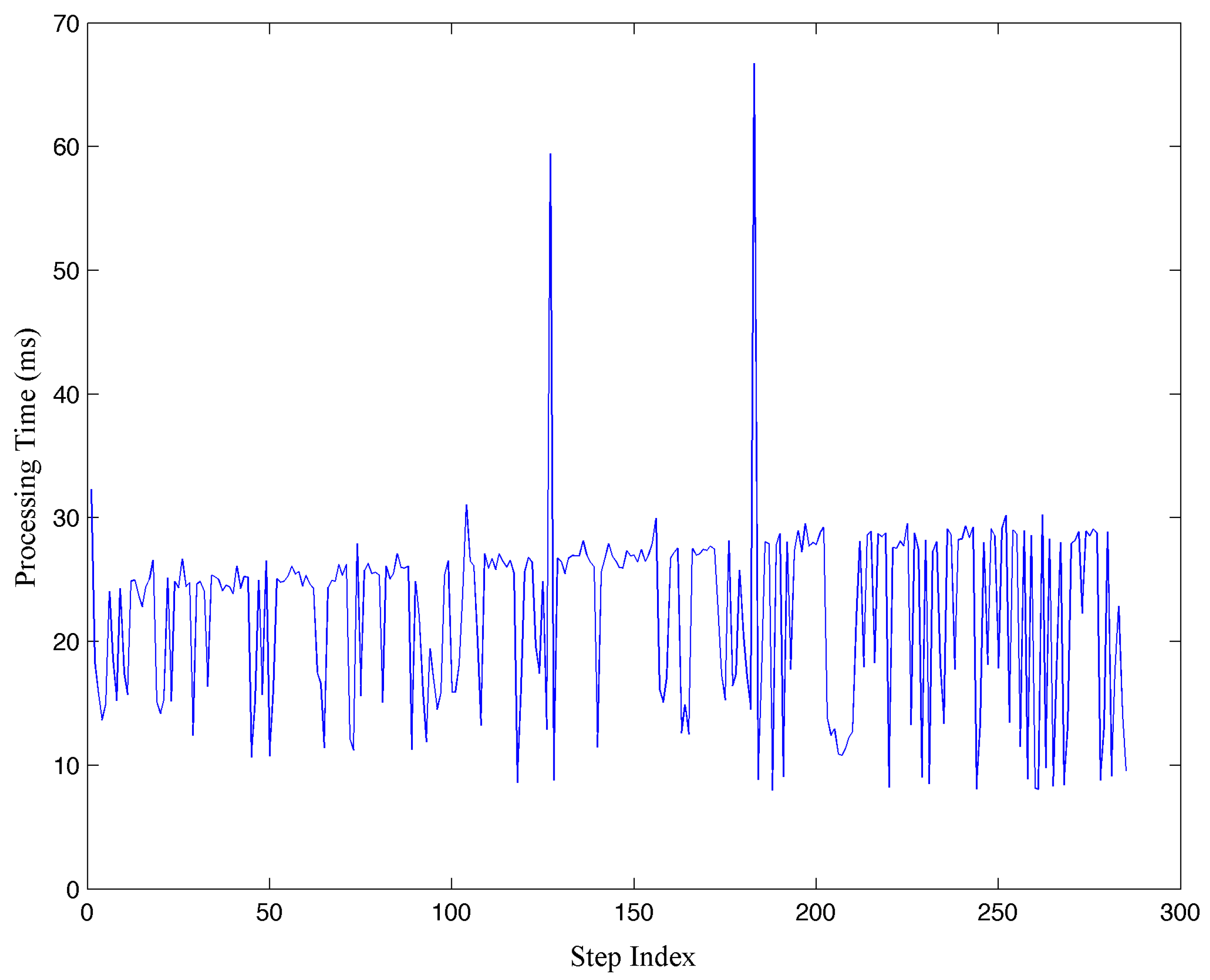
4.4. Discussions

5. Conclusions and Future Work
Acknowledgments
Author Contributions
Conflicts of Interest
References
- Du, Y.; Yang, D.; Xiu, C. A Novel Method for Constructing a WIFI Positioning System with Efficient Manpower. Sensors 2015, 15, 8358–8381. [Google Scholar] [CrossRef] [PubMed]
- Au, A.W.S.; Chen, F.; Valaee, S.; Reyes, S.; Sorour, S.; Markowitz, S.N.; Gold, D.; Gordon, K.; Eizenman, M. Indoor Tracking and Navigation Using Received Signal Strength and Compressive Sensing on a Mobile Device. IEEE Trans. Mob. Comput. 2013, 12, 2050–2062. [Google Scholar] [CrossRef]
- Zhang, P.; Zhao, Q.; Li, Y.; Niu, X.; Zhuang, Y.; Liu, J. Collaborative WiFi Fingerprinting Using Sensor-Based Navigation on Smartphones. Sensors 2015, 15, 17534–17557. [Google Scholar] [CrossRef] [PubMed]
- Shikur, B.Y.; Weber, T. TDOA/AOD/AOA localization in NLOS environments. In Proceedings of the IEEE International Conference on Acoustics, Speech and Signal Processing, Florence, Italy, 4–9 May 2014; pp. 6518–6522.
- Mario, M.; Pedro, J.M.; Carlos, D.K. Using Bluetooth to implement a pervasive indoor positioning system with minimal requirements at the application level. Mob. Inf. Syst. 2012, 8, 73–82. [Google Scholar]
- Lim, A.; Zhang, K. A Robust RFID-Based Method for Precise Indoor Positioning. In Advances in Applied Artificial Intelligence; Springer: Berlin, Germany, 2006; pp. 1189–1199. [Google Scholar]
- Hsu, C.-C.; Chen, J.-H. A Novel Sensor-Assisted RFID-Based Indoor Tracking System for the Elderly Living Alone. Sensors 2011, 11, 10094–10113. [Google Scholar] [CrossRef] [PubMed]
- Na, J. The Blind Interactive Guide System Using RFID-Based Indoor Positioning System. In Computers Helping People with Special Needs; Springer: Berlin, Germany, 2006; pp. 1298–1305. [Google Scholar]
- Ozdenizci, B.; Kerem, O.; Coskun, V.; Aydin, M.N. Development of an Indoor Navigation System Using NFC Technology. In Proceedings of the Fourth International Conference on Information and Computing, Phuket Island, Thailand, 25–27 April 2011; pp. 11–14.
- Puertolas-Montañez, J.A.; Mendoza-Rodriguez, A.; Sanz-Prieto, I. Smart Indoor Positioning/ Location and Navigation: A Lightweight Approach. Int. J. Interact. Multimed. Artif. Intel. 2013, 2, 43–50. [Google Scholar]
- Akeila, E.; Salcic, Z.; Swain, A. Reducing low-cost INS error accumulation in distance estimation using self-resetting. IEEE Trans. Instrum. Meas. 2014, 63, 177–184. [Google Scholar] [CrossRef]
- Muhammad, M.N.; Salcic, Z.; I. Wang, K. Subtractive clustering as ZUPT detector. In Proceedings of the IEEE 11th International Conference on Ubiquitous Intelligence and Computing, Bali, Indonesia, 9–12 December 2014.
- Lan, K.C.; Shih, W.Y. On calibrating the sensor errors of a PDR-based indoor localization system. Sensors 2013, 13, 4781–4810. [Google Scholar] [CrossRef] [PubMed]
- Antonio, R.J.; Fernando, S.; Francisco, Z.; Jose, C.P.; Jorge, G. PDR with foot-mounted IMU and ramp detection. Sensors 2011, 11, 9393–9410. [Google Scholar]
- Bao, H.; Wong, W.-C. A Novel Map-Based Dead-Reckoning Algorithm for Indoor Localization. J. Sens. Actuator Netw. 2014, 3, 44–63. [Google Scholar] [CrossRef]
- Zengshan, T.; Yuan, Z.; Mu, Z.; Yu, L. Pedestrian dead reckoning for MARG navigation using a smartphone. EURASIP J. Adv. Sign. Process. 2014, 1, 1–9. [Google Scholar]
- Mikov, A.; Moschevikin, A.; Fedorov, A.; Sikora, A. A localization system using inertial measurement units from wireless commercial hand-held devices. In Proceedings of the International Conference on Indoor Positioning and Indoor Navigation, Belfort, France, 28–31 October 2013.
- Qian, J.; Ma, J.; Ying, R.; Liu, P.; Pei, L. An improved indoor localization method using smartphone inertial sensors. In Proceedings of the International Conference on Indoor Positioning and Indoor Navigation, Belfort, France, 28–31 October 2013.
- Shih, W.Y.; Chen, L.Y.; Lan, K.C. Estimating Walking Distance with a Smart Phone. In Proceedings of the Fifth International Symposium on Parallel Architectures, Algorithms and Programming, Taipei, Taiwan, 17–20 December 2012; pp. 166–171.
- Tian, Q.; Zoran, S.; I-Kai Wang, K.; Pan, Y. An enhanced pedestrian dead reckoning approach for pedestrian tracking using smartphones. In Proceedings of the IEEE Tenth International Conference on Intelligent Sensors, Sensor Networks and Information Processing, Singapore, 7–9 April 2015.
- Kang, W.; Han, Y. SmartPDR: Smartphone-based pedestrian dead reckoning for indoor localization. IEEE Sens. J. 2015, 15, 2906–2916. [Google Scholar] [CrossRef]
- Jin, Y.; Soh, W.S.; Motani, M.; Wong, W.C. A Robust Indoor Pedestrian Tracking System with Sparse Infrastructure Support. IEEE Trans. Mob. Comput. 2013, 12, 1392–1403. [Google Scholar] [CrossRef]
- Lee, S.; Kim, B.; Kim, H.; Ha, R.; Cha, H. Inertial Sensor-Based Indoor Pedestrian Localization with Minimum 802.15.4a Configuration. IEEE Trans. Ind. Inf. 2011, 7, 455–466. [Google Scholar] [CrossRef]
- Ebner, F.; Deinzer, F.; Koping, L.; Grzegorzek, M. Robust self-localization using Wi-Fi, step/turn-detection and recursive density estimation. In Proceedings of the International Conference on Indoor Positioning and Indoor Navigation, Busan, Korea, 27–30 October 2014.
- Zhang, R.; Xia, W.; Jia, Z.; Shen, L. The indoor localization method based on the integration of RSSI and inertial sensor. In Proceedings of the IEEE 3rd Global Conference on Consumer Electronics, Tokyo, Japan, 7–10 October 2014; pp. 332–336.
- Edwan, E.; Bourimi, M.; Joram, N.; Al-Qudsi, B.; Ellinger, F. NFC/INS integrated navigation system: The promising combination for pedestrians’ indoor navigation. In Proceedings of the International Symposium on Fundamentals of Electrical Engineering, Bucharest, Romania, 28–29 November 2014; pp. 1–5.
- Ruiz, A.R.J.; Granja, F.S.; Prieto, H.J.C.; Rosas, J.I.G. Accurate Pedestrian Indoor Navigation by Tightly Coupling Foot-Mounted IMU and RFID Measurements. IEEE Trans. Instrum. Meas. 2012, 61, 178–189. [Google Scholar] [CrossRef]
- Chirakkal, V.V.; Park, M.; Han, D.S. Exploring Smartphone-Based Indoor Navigation: A QR Code Assistance-Based Approach. IEIE Trans. Smart Process. Comput. 2015, 4, 173–182. [Google Scholar] [CrossRef]
- Langer, M.; Kiesel, S.; Ascher, C.; Trommer, G.F. Deeply Coupled GPS/INS integration in pedestrian navigation systems in weak signal conditions. In Proceedings of the International Conference on Indoor Positioning and Indoor Navigation, Sydney, Australia, 13–15 November 2012.
- Chen, L.; Hu, H. IMU/GPS based pedestrian localization. In Proceedings of the 4th Computer Science and Electronic Engineering Conference, Colchester, UK, 12–13 September 2012; pp. 23–28.
- Pratama, A.R.; Widyawan; Hidayat, R. Smartphone-based pedestrian dead reckoning as an indoor positioning system. In Proceedings of the International Conference on System Engineering and Technology, Bandung, Indonesia, 11–12 September 2012.
- Zhang, R.; Bannoura, A.; Hoflinger, F.; Reindl, L.M.; Schindelhauer, C. Indoor localization using a smart phone. In Proceedings of the IEEE Sensors Applications Symposium (SAS), Galveston, TX, USA, 19–21 February 2013; pp. 38–42.
- Gordon, N.J.; Salmond, D.J.; Smith, A.F.M. Novel approach to nonlinear/non-Gaussian Bayesian state estimation. IEE Pro. F Radar Sign. Process. 1993, 140, 107–113. [Google Scholar] [CrossRef]
- Chateau, J.; Rousseau, P.; Albiston, G.; Cook, B.; Papanastasiou, S.; Peytchev, E. Implementation and evaluation of particle filtering for indoor positioning. In Proceedings of the IEEE Symposium on Computers and Communication (ISCC), Madeira, Portugal, 23–26 June 2014.
- Carpenter, J.; Clifford, P.; Fearnhead, P. Improved particle filter for nonlinear problems. IEE Pro. Radar Sonar Navig. 1999, 146, 2–7. [Google Scholar] [CrossRef]
© 2015 by the authors; licensee MDPI, Basel, Switzerland. This article is an open access article distributed under the terms and conditions of the Creative Commons by Attribution (CC-BY) license (http://creativecommons.org/licenses/by/4.0/).
Share and Cite
Tian, Q.; Salcic, Z.; Wang, K.I.-K.; Pan, Y. A Hybrid Indoor Localization and Navigation System with Map Matching for Pedestrians Using Smartphones. Sensors 2015, 15, 30759-30783. https://0-doi-org.brum.beds.ac.uk/10.3390/s151229827
Tian Q, Salcic Z, Wang KI-K, Pan Y. A Hybrid Indoor Localization and Navigation System with Map Matching for Pedestrians Using Smartphones. Sensors. 2015; 15(12):30759-30783. https://0-doi-org.brum.beds.ac.uk/10.3390/s151229827
Chicago/Turabian StyleTian, Qinglin, Zoran Salcic, Kevin I-Kai Wang, and Yun Pan. 2015. "A Hybrid Indoor Localization and Navigation System with Map Matching for Pedestrians Using Smartphones" Sensors 15, no. 12: 30759-30783. https://0-doi-org.brum.beds.ac.uk/10.3390/s151229827