
A Novel Method for Constructing a WIFI Positioning System with Efficient Manpower

Abstract
:1. Introduction
2. Methodology
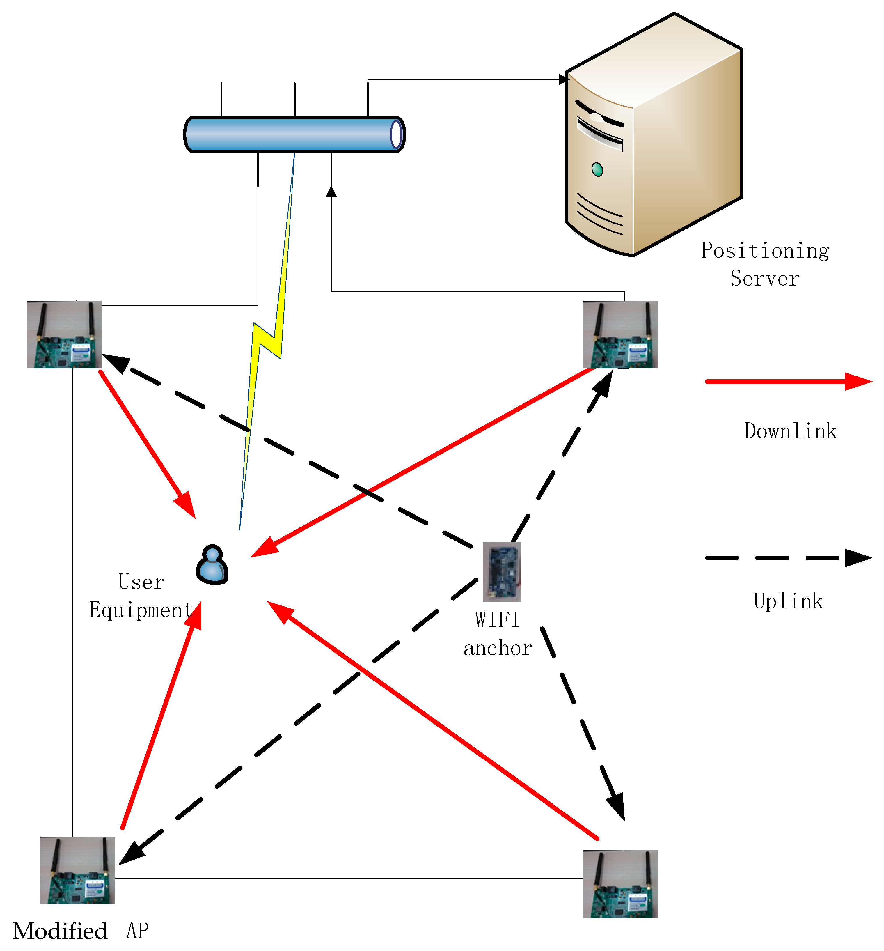
2.1. Proposed Model


| — | |||
| — | |||
| — |
2.2. RGWR Algorithm
2.2.1. Constructing Radio Map
- ➢
- The RSSIs among neighboring locations always exhibit some level of correlations.
- ➢
- Signal attenuation models vary in different regions.
2.2.2. Deployment of the WIFI Anchors
2.2.3. Updating Radio Map

2.3. Positioning
3. Experiments Section
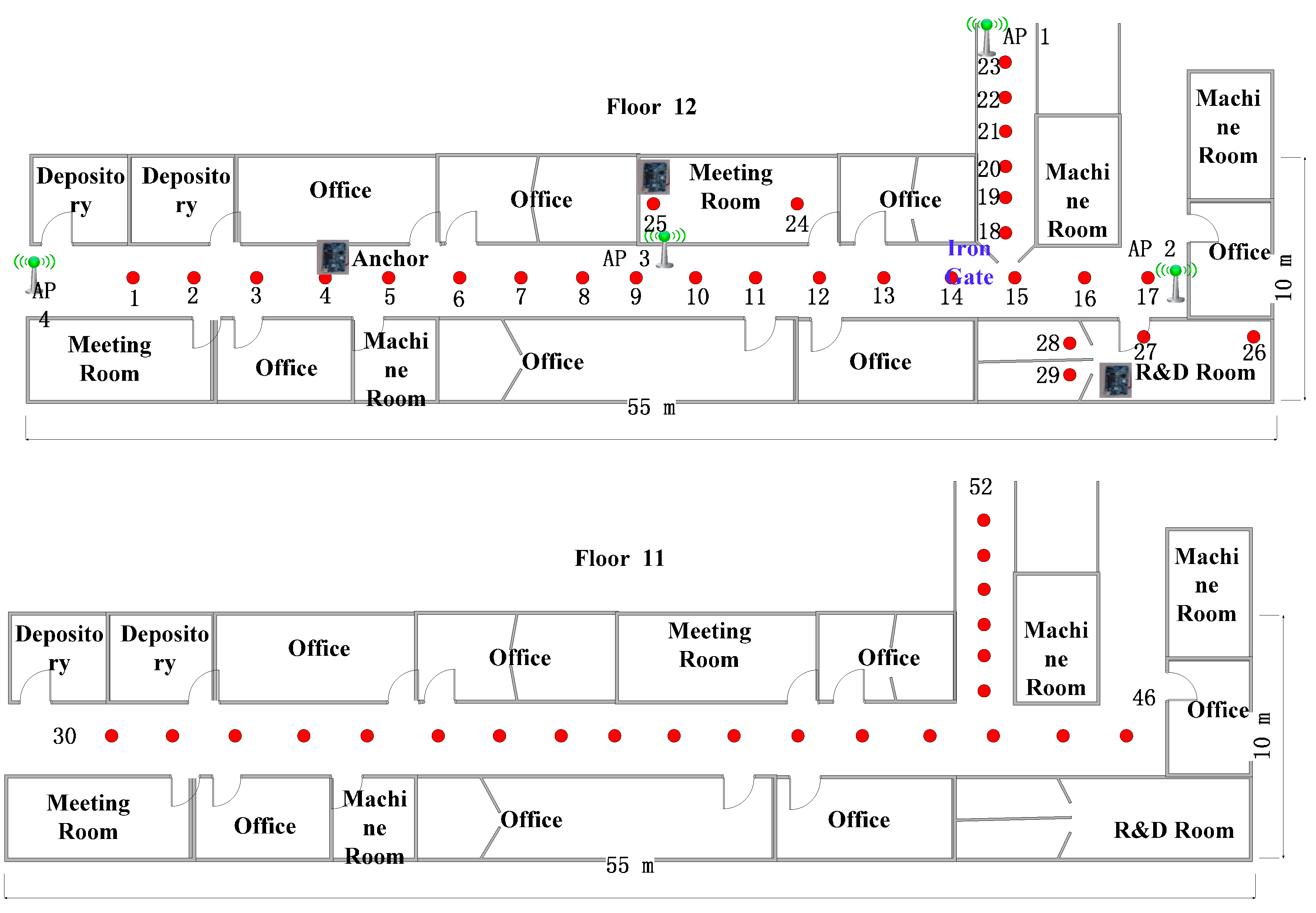
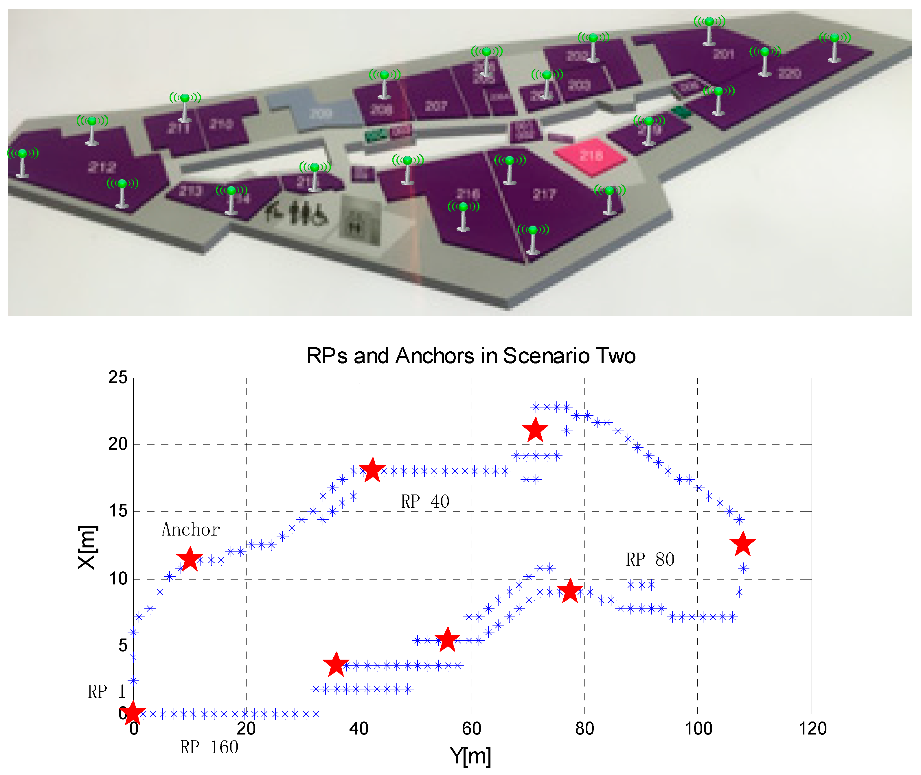
3.1. Experimental Setup

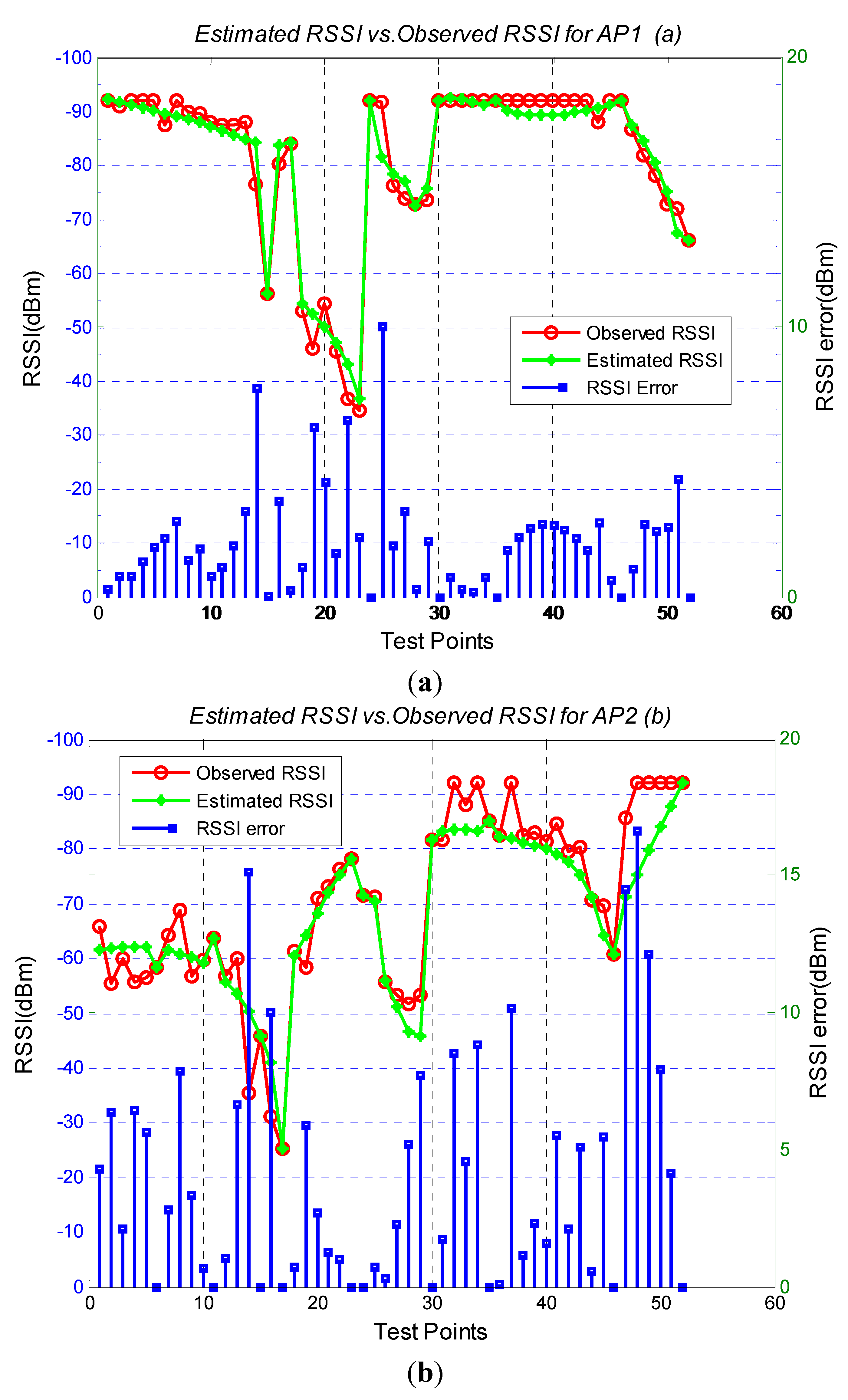
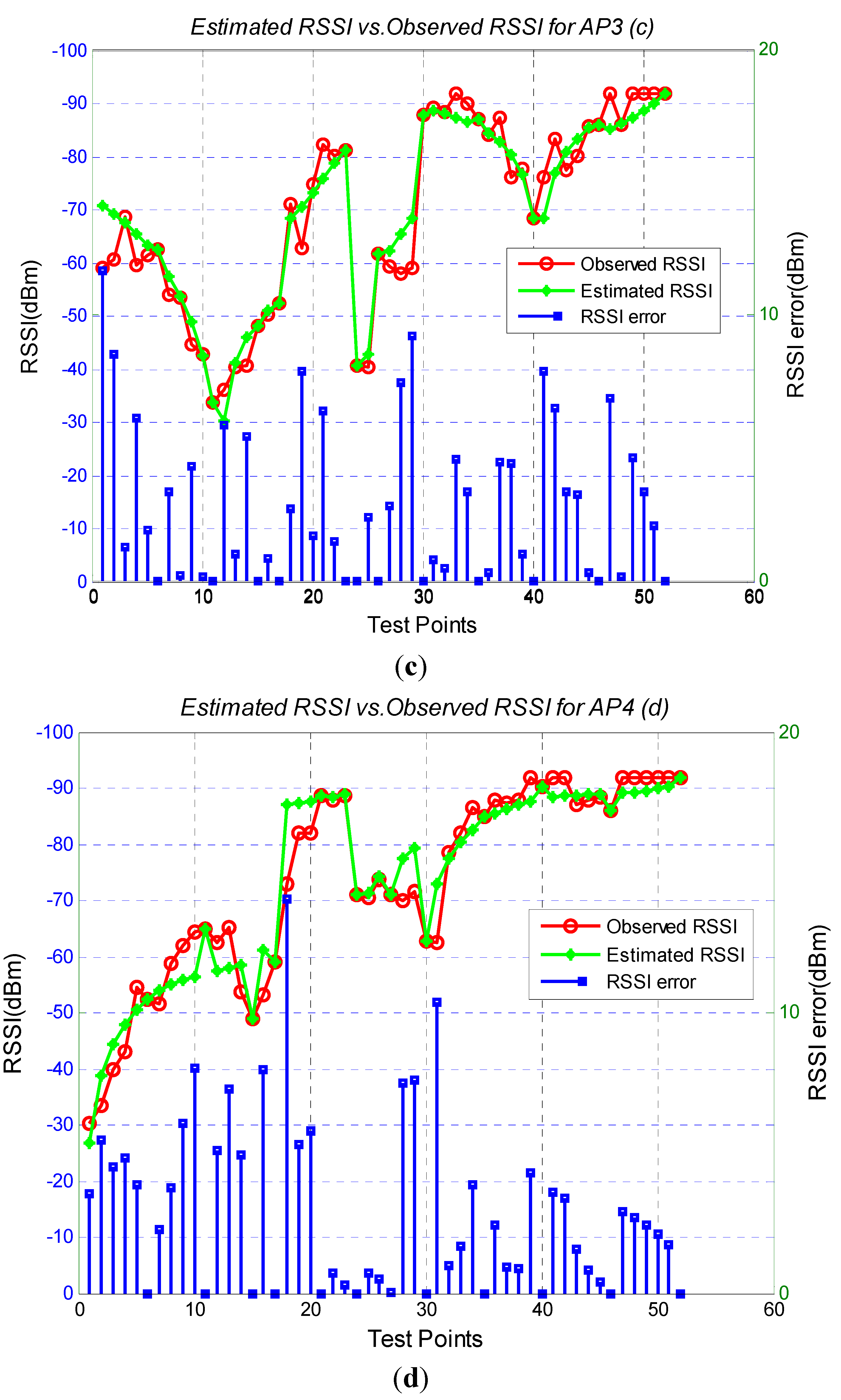
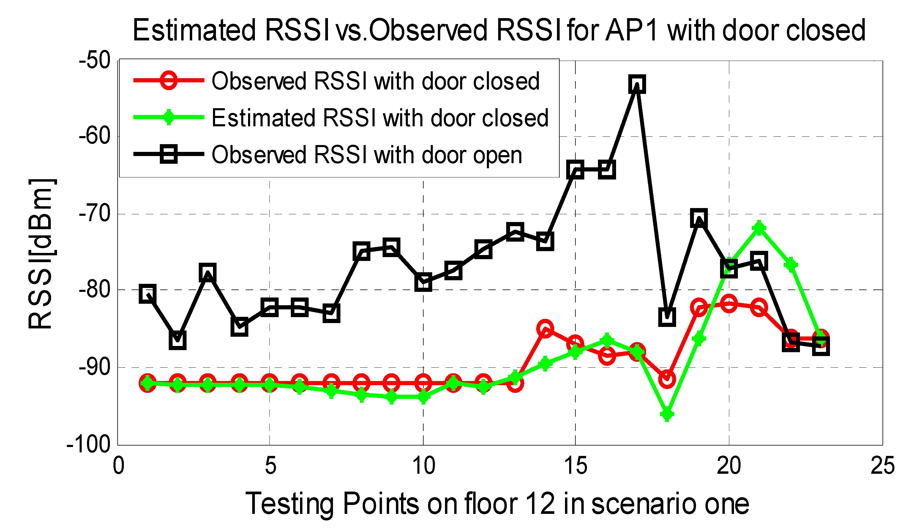
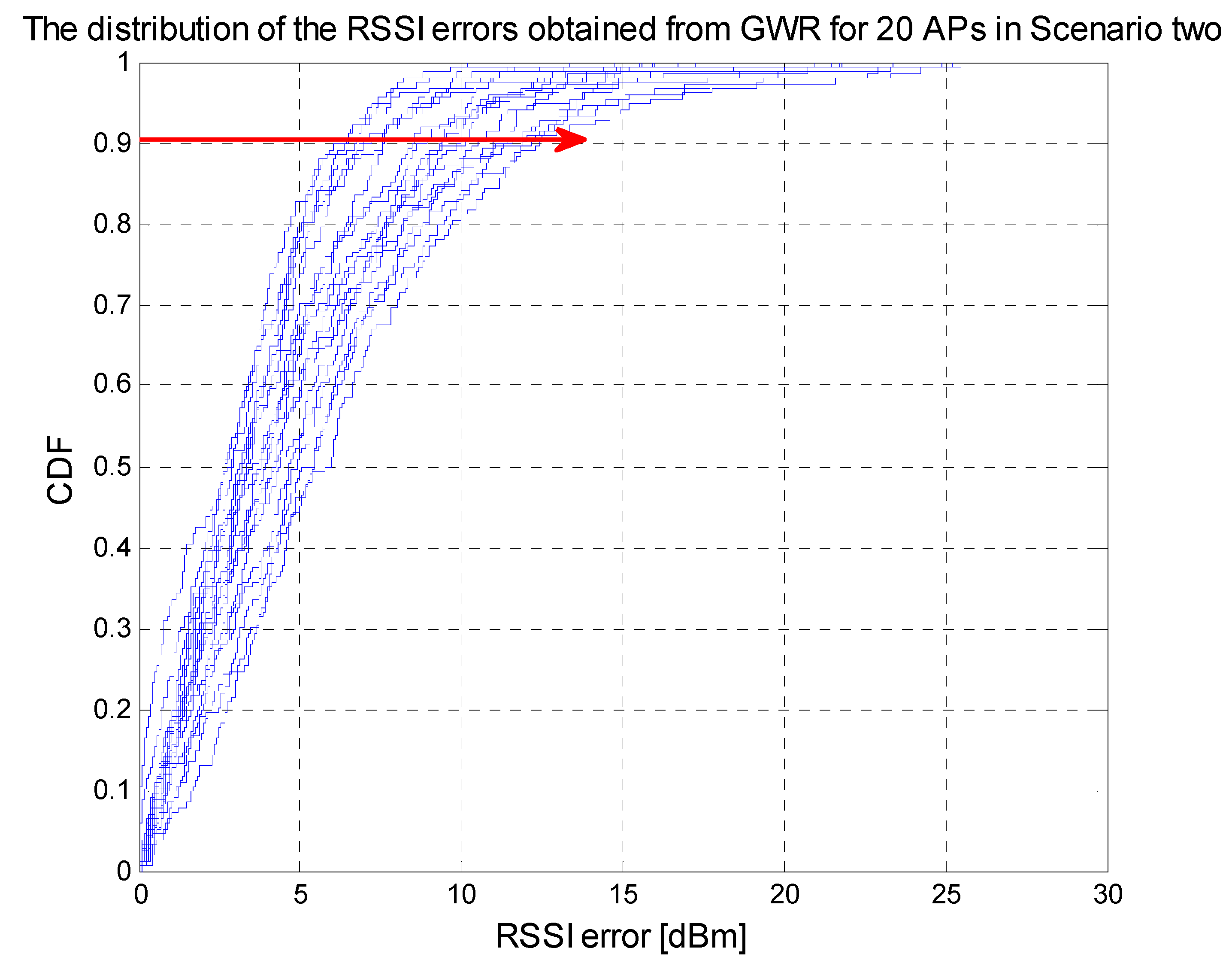
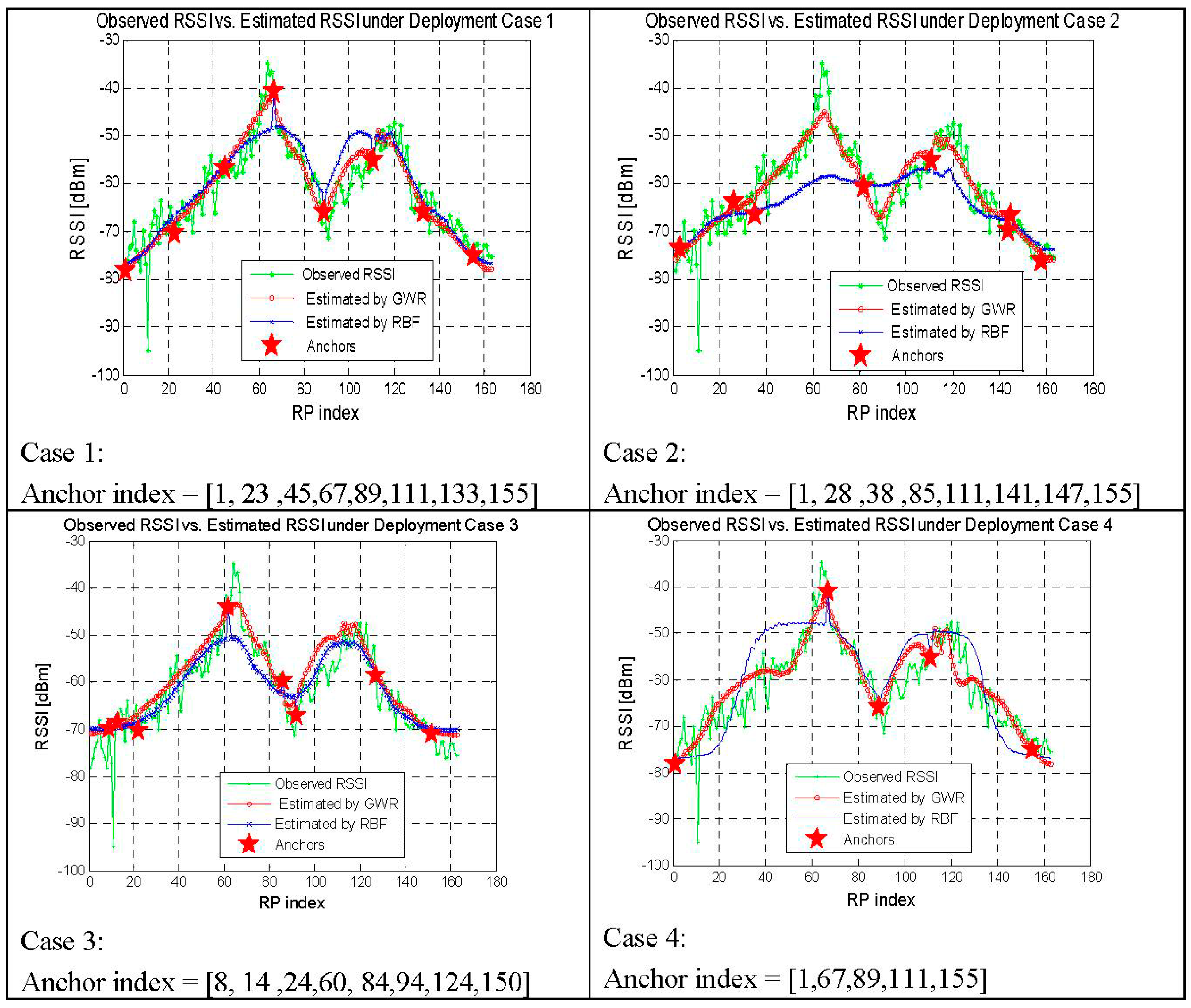
3.2. RSSI Estimation Accuracy


| AP1 | AP2 | AP3 | AP4 | Average | |
|---|---|---|---|---|---|
| Scenario one | 3.48 | 4.12 | 3.66 | 3.79 | 3.76 |
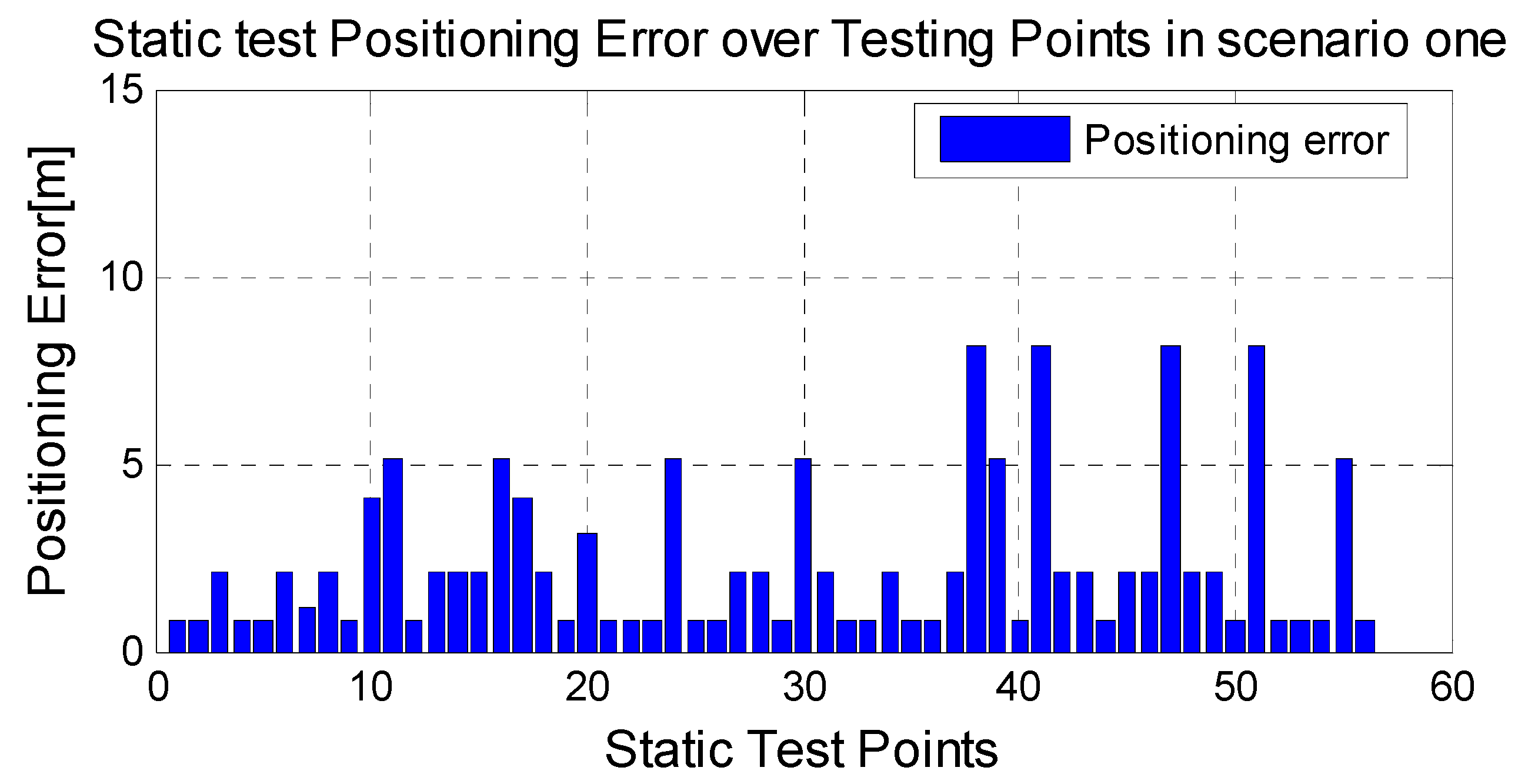
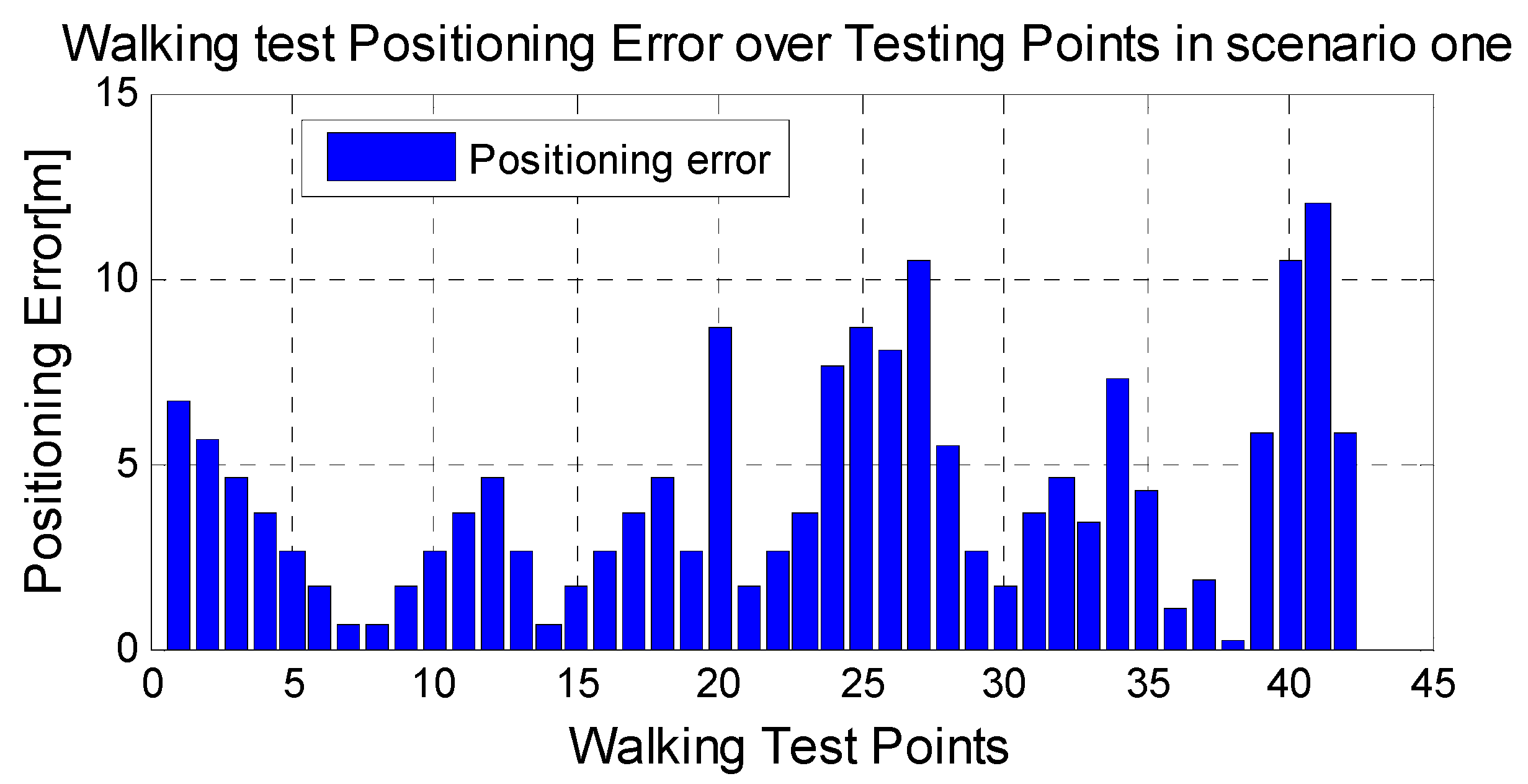
3.3. Location Estimation Accuracy
Static Test and Dynamic Test


| Number of Anchors | 0 | 1 | 2 | 3 |
|---|---|---|---|---|
| Static Test(m) | 8.3 m | 5.3 m | 4.0 m | 2.4 m |
| Walking Test(m) | 9.2 m | 6.8 m | 5.9 m | 4.2 m |
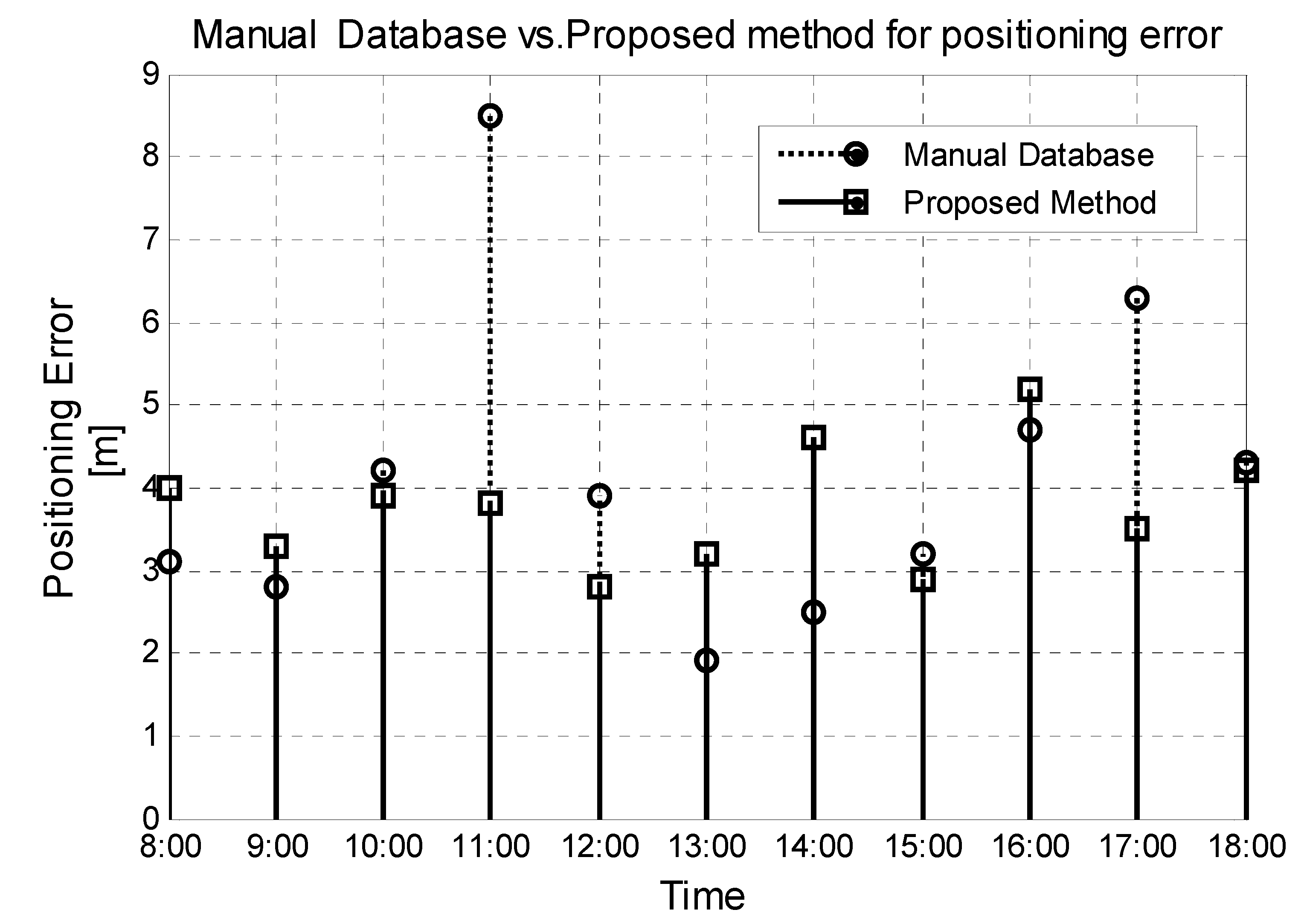
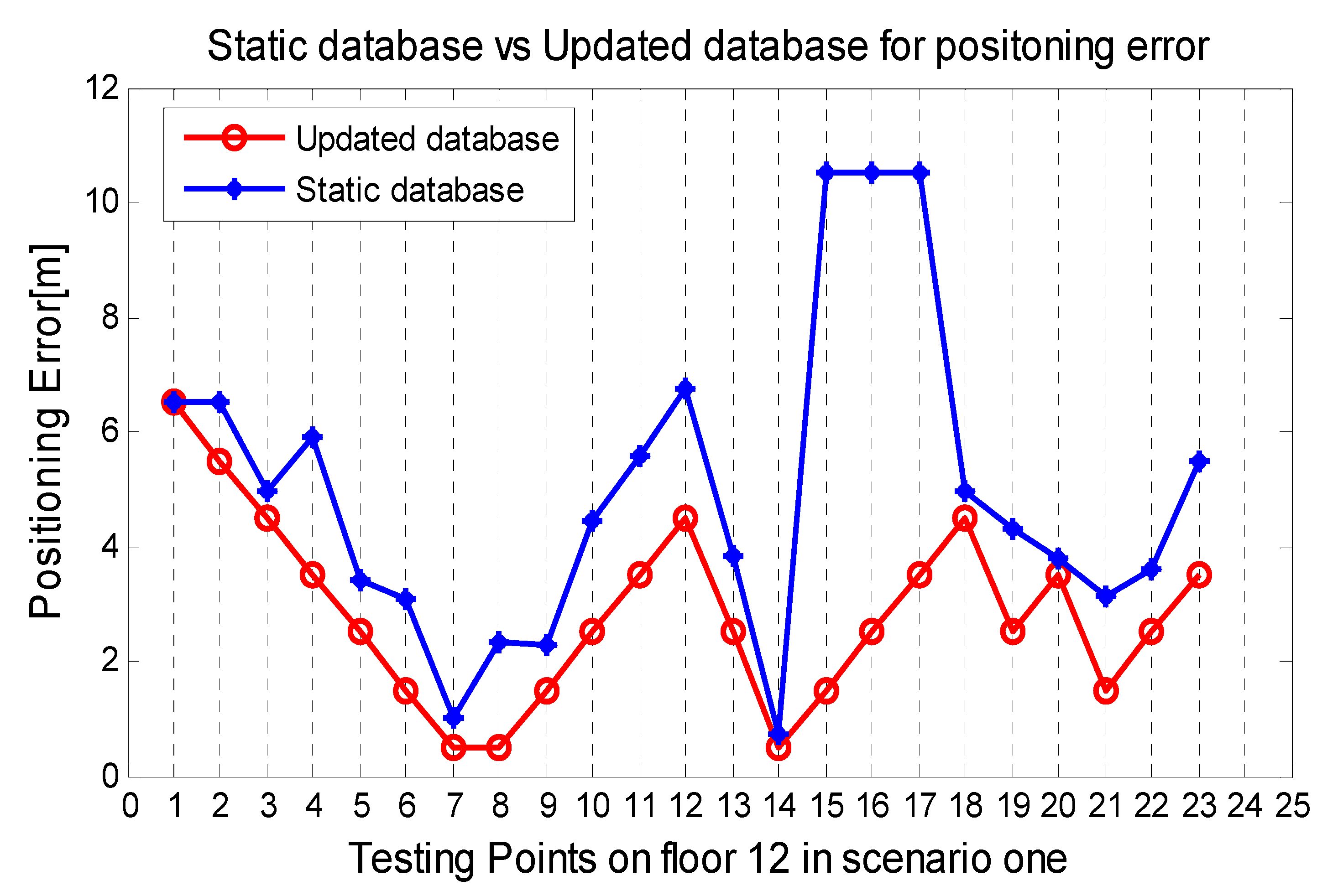
3.4. Solution for the Changes Caused by Time and Environment


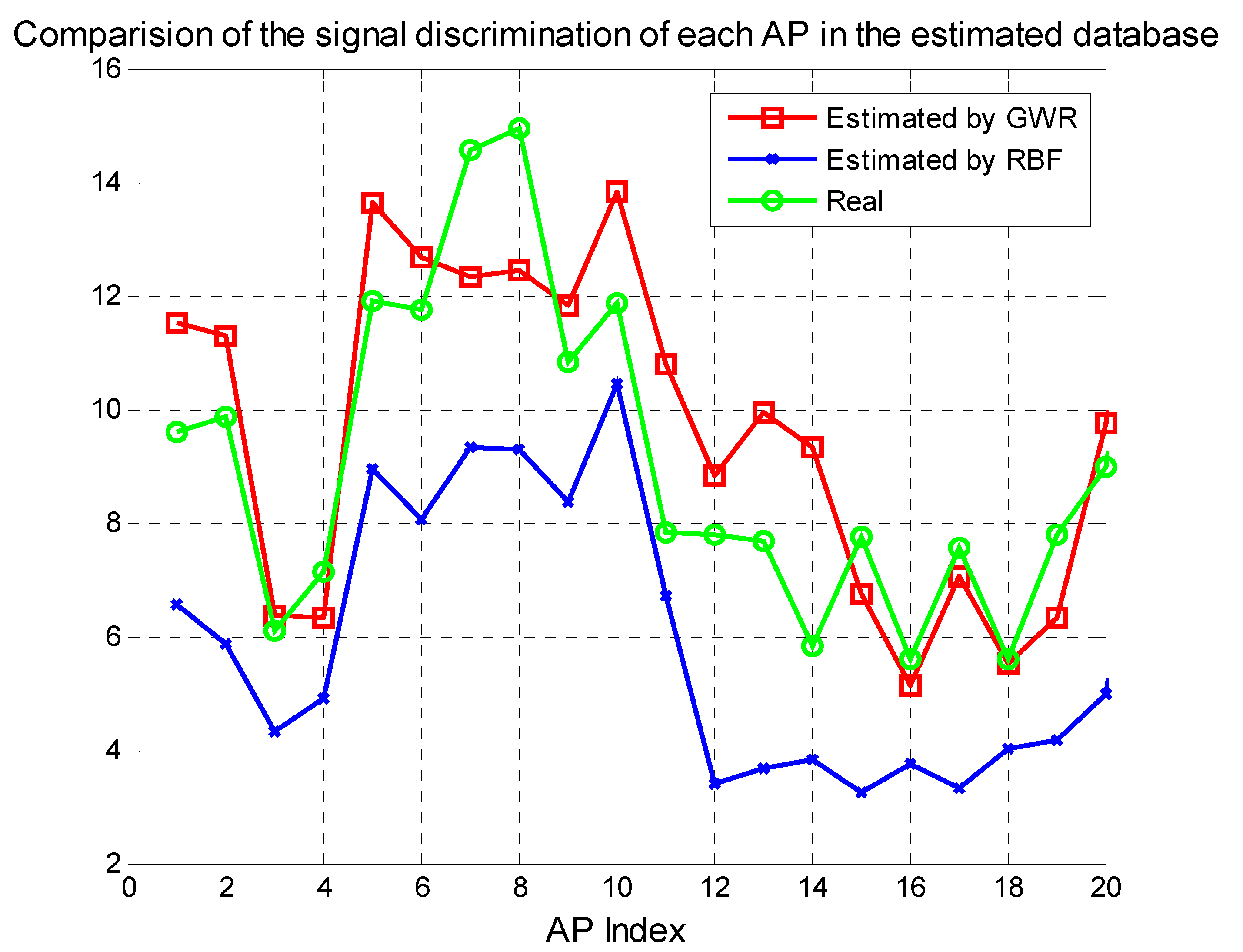
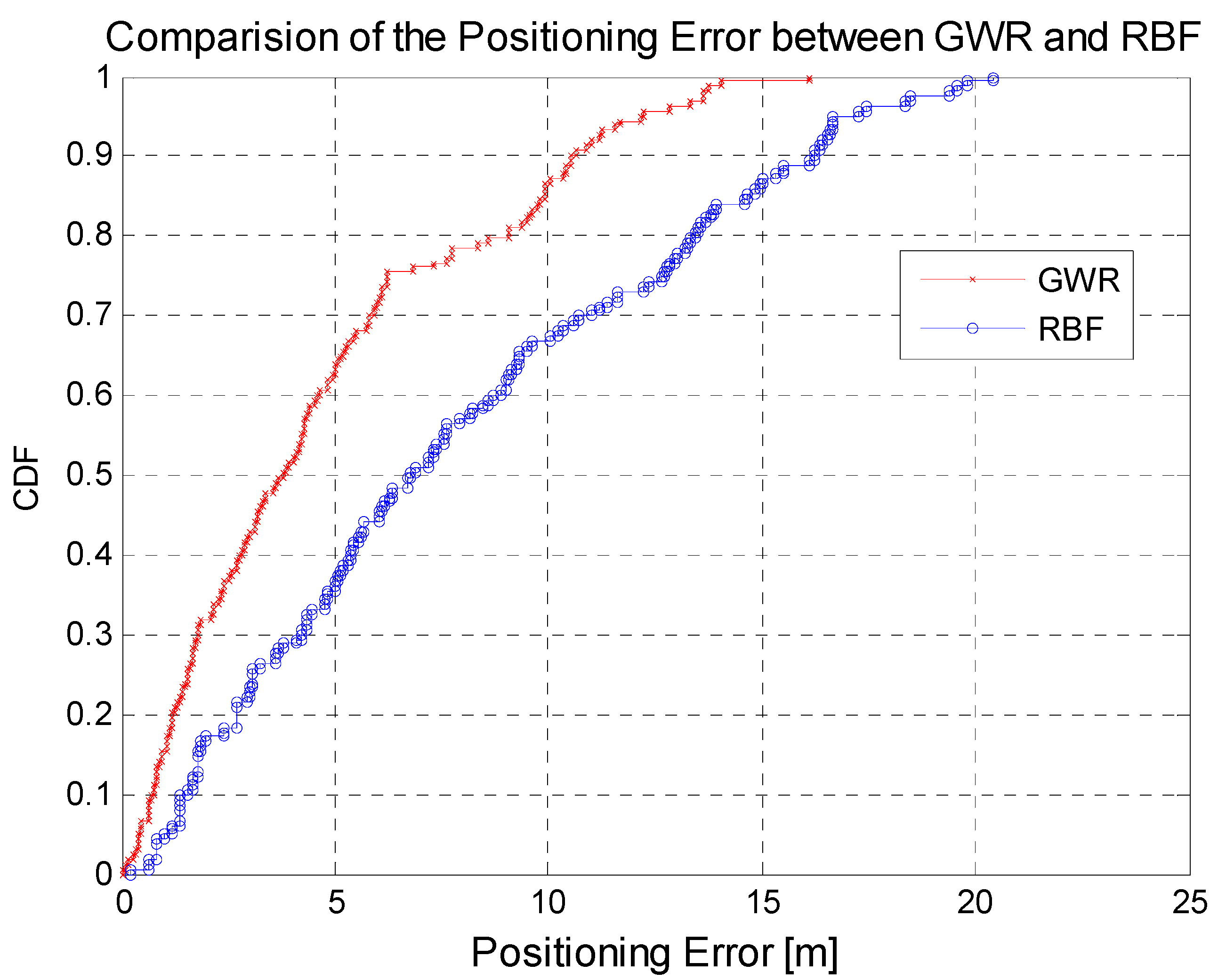
3.5. Further Evaluation


| AP Index | 1 | 2 | 3 | 4 | 5 | 6 | 7 | 8 | 9 | 10 |
|---|---|---|---|---|---|---|---|---|---|---|
| RBF | 4.5 | 3.9 | 4.3 | 4.7 | 3.8 | 3.9 | 5.9 | 5.7 | 6.1 | 4.5 |
| GWR | 3.1 | 3.6 | 3.6 | 4.0 | 3.3 | 3.4 | 4.9 | 5.0 | 4.2 | 3.4 |
| AP index | 11 | 12 | 13 | 14 | 15 | 16 | 17 | 18 | 19 | 20 |
| RBF | 5.9 | 7.2 | 5.2 | 5.1 | 5.7 | 7.5 | 6.3 | 4.9 | 5.6 | 5.2 |
| GWR | 4.6 | 6.0 | 5.4 | 5.2 | 5.2 | 6.3 | 5.6 | 5.2 | 4.1 | 3.9 |


4. Conclusions
Acknowledgments
Author Contributions
Conflicts of Interest
References
- Gu, Y.; Lo, A.; Niemegeers, I. A survey of indoor positioning systems for wireless personal networks. IEEE Commun. Surv. Tutor. 2009, 11, 13–32. [Google Scholar] [CrossRef]
- Hui, L.; Darabi, H.; Banerjee, P.; Jing, L. Survey of Wireless Indoor Positioning Techniques and Systems. IEEE Trans. Syst. Man Cybern. Part C 2007, 37, 1067–1080. [Google Scholar] [CrossRef]
- Mahtab Hossain, A.; Jin, Y.; Soh, W.-S.; Van, H.N. SSD: A robust RF location fingerprint addressing mobile devices heterogeneity. IEEE Trans. Mob. Comput. 2013, 12, 65–77. [Google Scholar]
- Kjargaard, M.B. Indoor location fingerprinting with heterogeneous clients. Pervasive Mob. Comput. 2011, 7, 31–43. [Google Scholar] [CrossRef]
- Yu, K.; Dutkiewicz, E. NLOS identification and mitigation for mobile tracking. IEEE Trans. Aerosp. Electron. Syst. 2013, 49, 1438–1452. [Google Scholar] [CrossRef]
- Mihaylova, L.; Angelova, D.; Bull, D.; Canagarajah, N. Localization of mobile nodes in wireless networks with correlated in time measurement noise. IEEE Trans. Mob. Comput. 2011, 10, 44–53. [Google Scholar] [CrossRef] [Green Version]
- Fang, S.; Wang, C.; Tsao, Y. Compensating for Orientation Mismatch in Robust WIFI Localization Using Histogram Equalization. IEEE Trans.Veh. Technol. 2014, PP. [Google Scholar] [CrossRef]
- Liu, J.; Chen, R.; Pei, L.; Guinness, R.; Kuusniemi, H. A Hybrid Smartphone Indoor Positioning Solution for Mobile LBS. Sensors 2012, 12, 17208–17233. [Google Scholar] [CrossRef] [PubMed]
- Au, A.W.S.; Chen, F.; Valaee, S.; Reyes, S.; Sorour, S.; Markowitz, S.N.; Gold, D.; Gordon, K.; Eizenman, M. Indoor Tracking and Navigation Using Received Signal Strength and Compressive Sensing on a Mobile Device. IEEE Trans. Mob. Comput. 2013, 12, 2050–2062. [Google Scholar] [CrossRef]
- MikkelBaun, K.; Valdemar, M.C. Hyperbolic Location Fingerprinting: A Calibration-free Solution for Handling Differences in Signal Strength (concise contribution). In Proceedings of the IEEE Sixth Annual IEEE International Conference on Pervasive Computing and Communications, Hong Kong, China, 17–21 March 2008; pp. 110–116.
- Chai, X.; Yang, Q. Reducing the calibration effort for probabilistic indoor location estimation. IEEE Trans. Mob. Comput. 2007, 6, 649–662. [Google Scholar] [CrossRef]
- Wang, H.; Ma, L.; Xu, Y.; Deng, Z. Dynamic Radio Map Construction for WLAN Indoor Location. In Proceedings of the 2011 International Conference on Intelligent Human-Machine Systems and Cybernetics (IHMSC), Hangzhou, China, August 2011; Volume 2, pp. 162–165.
- Lee, M.; Han, D. QRLoc: User-involved Calibration Using Quick Response Codes for Wi-Fi Based Indoor localization. In Proceedings of the 2012 7th International Conference on Computing and Convergence Technology (ICCCT), Seoul, Korea, 3–5 December 2012; pp. 1460–1465.
- Bisio, I.; Cerruti, M.; Lavagetto, F.; Marchese, M.; Pastorino, M.; Randazzo, A.; Sciarrone, A. A Training less WIFI Fingerprint Positioning Approach Over Mobile Devices. IEEE Antennas Wirel. Propag. Lett. 2014, 13, 832–835. [Google Scholar] [CrossRef]
- Shih, C.Y.; Chen, L.H.; Chen, G.H.; Wu, E.K.; Jin, M.H. Intelligent Radio Map Management for Future WLAN Indoor Location Fingerprinting. In Proceedings of the Wireless Communications and Networking Conference (WCNC), Shanghai, China, 1–4 April 2012; pp. 2769–2773.
- Lesser, A.M.; Okoniewski, M.; Nielsen, J. A Modified Fingerprinting Technique for an Indoor, Range-free, Localization system with Dynamic Radio Map Annealing over Time. In Proceedings of the 2012 IEEE International Conference on Wireless Information Technology and Systems (ICWITS), Maui, HI, USA, 11–16 November 2012; pp. 1–4.
- Cai, X.; Chen, L.; Chen, G. Constructing Adaptive Indoor Radio Maps for Dynamic Wireless Environments. In Proceedings of the 2013 IEEE 10th International Conference on Ubiquitous Intelligence and Computing, and 10th International Conference on Autonomic and Trusted Computing (UIC/ATC), Vietri sul Mere, Italy, 18–21 December 2013; pp. 41–47.
- Song, L.; Chen, Y.; Trappe, W.; Greenstein, L.J. Non-interactive Localization of Cognitive Radios Based on Dynamic Signal Strength Mapping. In Proceedings of the IEEE Sixth International Conference on Wireless on-Demand Network Systems and Services, Snowbird, UT, USA, 2–4 February 2009; pp. 85–92.
- Liu, X.; Zhang, S.; Lu, H.; Lin, X. Method for Efficiently Constructing and Updating Radio Map of Fingerprint Positioning. In Proceedings of the IEEE GLOBECOM Workshops (GC Workshps), Miami, FL, USA, 6–10 December 2010; 2010; pp. 74–78. [Google Scholar]
- Kim, Y.; Chon, Y.; Cha, H. Smartphone-based collaborative and autonomous radio fingerprinting. IEEE Trans. Syst. Man Cybern. Part C 2012, 42, 112–122. [Google Scholar] [CrossRef]
- Bolliger, P.; Partridge, K.; Chu, M. Improving location fingerprinting through motion detection and asynchronous interval labeling. In Location and Context Awareness; Springer: Berlin/Heidelberg, Germany, 2009; Volume 5561, pp. 37–51. [Google Scholar]
- Sorour, S.; Lostanlen, Y.; Valaee, S. Reduced-effort Generation of Indoor Radio Maps Using Crowdsourcing and Manifold Alignment. In Proceedings of the IEEE 2012 Sixth International Symposium on Telecommunications (IST), Tehran, Iran, 6–8 November 2012; pp. 354–358.
- Atia, M.M.; Noureldin, A.; Korenberg, M.J. Dynamic Online-Calibrated Radio Maps for Indoor Positioning in Wireless Local Area Networks. IEEE Trans. Mob. Comput. 2013, 12, 1774–1787. [Google Scholar] [CrossRef]
- Ahn, H.; Yu, W. Environmental-Adaptive RSSI-Based Indoor Localization. IEEE Trans. Autom. Sci. Eng. 2009, 6, 626–633. [Google Scholar] [CrossRef]
- Ni, L.; Liu, Y.; Lau, Y.C.; Patil, A. Landmarc: Indoor Location Sensing Using Active RFID. In Proceedings of the IEEE International Conference on Pervasive Computing and Communications (PerCom’03), Fort Worth, TX, USA, 26 March 2003; pp. 407–415.
- Krishnan, P.; Krishnakumar, A.; Ju, W.-H.; Mallows, C.; Gamt, S. A System for Lease: Location Estimation Assisted by Stationary Emitters for Indoor rf Wireless Networks. In Proceedings of the IEEE Conference on Computer Communications (INFOCOM’04), Hong Kong, China, 2004; pp. 1001–1011.
- Yin, J.; Yang, Q.; Ni, L. Learning adaptive temporal radio maps for signal-strength-based location estimation. IEEE Trans. Mob. Comput. 2008, 7, 869–883. [Google Scholar] [CrossRef]
- Sun, Z.; Chen, Y.; Qi, J.; Liu, J. Adaptive Localization through Transfer Learning in Indoor wi-fi Environment. In Proceedings of the Seventh International Conference on Machine Learning and Applications (ICMLA’08), San Diego, CA, USA, 11–13 December 2008; pp. 331–336.
- Wang, Q.; Chen, X.; Chen, R.; Chen, Y.; Zhang, X. Electromyography-Based Locomotion Patterns Classification and Personal Positioning Toward Improved Context-Awareness Applications. IEEE Trans. Syst. Man Cybern.-Syst. 2013, 43, 1216–1227. [Google Scholar] [CrossRef]
- Fotheringham, A.S.; Brunsdon, C.; Charlton, M. Geographically Weighted Regression; John Wiley and Sons: Chichester, UK, 2002. [Google Scholar]
- Kaya, A.O.; Greenstein, L.J. A New Path Loss Modeling Approach for In-building Wireless Networks. In Proceedings of the 2012 IEEE Global Communications Conference (GLOBECOM), Anaheim, CA, USA, 3–7 December 2012; pp. 5033–5037.
- Akiyama, T.; Teranishi, Y.; Okamura, S.; Shimojo, S. An Approach for Filtering Inaccurate Access Point Observation Report in WIFI Positioning System. In Proceedings of the 2010 IEEE International Conference on P2P, Parallel, Grid, Cloud and Internet Computing (3PGCIC), Fukuoka, Japan, 4–6 November 2010; pp. 517–520.
- Park, J.G.; Curtis, D.; Teller, S.; Ledlie, J. Implications of device diversity for organic localization. In Proceedings of the 2011 IEEE Proceedings INFOCOM, Shanghai, China, 10–15 April 2011; pp. 3182–3190.
- Figuera, C.; Rojo-álvarez, J.L.; Mora-Jiménez, I.; Guerrero-Curieses, A.; Wilby, M.; Ramos-López, J. Time-space sampling and mobile device calibration for WIFI indoor location systems. IEEE Trans. Mob. Comput. 2011, 10, 913–926. [Google Scholar] [CrossRef]
© 2015 by the authors; licensee MDPI, Basel, Switzerland. This article is an open access article distributed under the terms and conditions of the Creative Commons Attribution license (http://creativecommons.org/licenses/by/4.0/).
Share and Cite
Du, Y.; Yang, D.; Xiu, C. A Novel Method for Constructing a WIFI Positioning System with Efficient Manpower. Sensors 2015, 15, 8358-8381. https://0-doi-org.brum.beds.ac.uk/10.3390/s150408358
Du Y, Yang D, Xiu C. A Novel Method for Constructing a WIFI Positioning System with Efficient Manpower. Sensors. 2015; 15(4):8358-8381. https://0-doi-org.brum.beds.ac.uk/10.3390/s150408358
Chicago/Turabian StyleDu, Yuanfeng, Dongkai Yang, and Chundi Xiu. 2015. "A Novel Method for Constructing a WIFI Positioning System with Efficient Manpower" Sensors 15, no. 4: 8358-8381. https://0-doi-org.brum.beds.ac.uk/10.3390/s150408358