1. Introduction
In recent years, techniques for obtaining acoustic images have been developed rapidly. At present, acoustic images are associated with a wide variety of applications [
1], such as non-destructive testing of materials, medical imaging, underwater imaging, SONAR, geophysical exploration, etc. These techniques for obtaining acoustic images are based on the RADAR (RAdio Detection and Ranging) principles, which form an image of an object from the radio waves that have been reflected on it [
2]. RADAR systems require high-cost hardware and their application with people and specific materials is difficult, due to their low reflectivity. These are the reasons why acoustic imaging techniques, also called SODAR (Sound Detection and Ranging) techniques, were developed. These SODAR techniques, mainly based on the use of arrays, represent a simple, low-cost alternative for obtaining “acoustic images” of an object.
An array is an arranged set of identical sensors, excited in a specific manner [
3]. Microphone arrays are a particular case, used in applications such as speech processing, echo cancellation, localization, and sound sources separation [
4]. By using beamforming techniques [
5], the array beam pattern can be electronically steered to different spatial positions, allowing the discrimination of acoustic sources based on their position.
The authors of this paper have experience in the design [
6] and development of acoustic imaging systems, based in acoustic arrays, used in many different fields, such as detection and tracking systems [
7,
8], Ambient Assisted Living [
9], or biometric identification systems [
10,
11,
12]. The arrays used were ULA (Uniform Linear Array), formed by acoustic sensors distributed uniformly along a line. These arrays are simple, but limited to one dimension (azimuth or elevation) to estimate the spatial position of the sound source. In order to obtain spatial information in two dimensions, it is necessary to work with planar arrays with sensors distributed on a surface.
Working with planar arrays leads to an increase in both system complexity and space required by the acoustic sensors and the associated hardware, since the extension from a 1D array of N element, to a 2D array of N × N elements increases the number of the required channels in an order of N2. These factors are accentuated when the number of sensors to work with is large. In the design of a system for acquiring and processing signals from an acoustic array, it should be noted that costs and complexity are directly related to the number of channels/sensors of the system. A typical system to obtain acoustic images has four basic elements: sensors, signal conditioners, acquisition devices and signal processor. For the first three elements, system cost increases linearly with the number of channels, as each sensor needs a signal conditioner and an acquisition device.
Digital MEMS (Micro-Electro-Mechanical System) microphones include a microphone, a signal conditioner, and an acquisition device incorporated in the chip itself. For this reason, an acquisition and processing system based on MEMS microphone arrays is reduced to two basic elements: MEMS microphone and a processing system. This processing system is usually based on an FPGA (Field Programmable Gate Array), as it is a digital system with multiple I/O nodes. The integration of the microphone preamplifier and the ADC in a single chip significantly reduces costs, if compared with solutions based on analog microphones. This is one of the main reasons why MEMS microphones are used in acoustic arrays with a large number of channels. However, cost reduction is not the only advantage of working with MEMS microphones. This technology also reduces the space occupied by the system, which makes it feasible to build arrays with hundreds or even thousands of sensors.
Arrays of MEMS microphones are specially designed for acoustic source localization [
13,
14,
15]; however, they are also used in other applications such as DOA (direction of arrival) estimation for vehicles in motion [
16], speech processing [
17,
18], turbulence measurements [
19], identifying geometric dimensions and internal defects of concrete structures [
20], or acoustic imaging [
21,
22,
23]. The system presented in this paper has two main characteristics/novelties: (i) it is scalable using several subarrays or modules, increasing the number of sensors used, and reconfigurable in the position and orientation of the modules; and (ii) its multi-platform framework is reconfigurable. These characteristics made our system flexible and suitable for many different applications. Many of the systems found on the literature show fixed solutions to particular problems, where the hardware is not scalable or the software is not reconfigurable as in the system that is proposed in this paper. The system shown in [
22] is reconfigurable, i.e., in the position of its modules, but its acquisition framework, based on an USB port, limits the maximum number of sensors that could be added to the system. For its part, the system shown by Turqueti [
16] is scalable; it allows multiple arrays to be aggregated, as the system detailed in this paper. However, our system has two advantages in comparison with Turqueti’s system: (i) it can be a standalone system, due to the use of a myRIO platform (embedded hardware with a FPGA and an ARM processor) as an acquisition and data processing system; and (ii) it allows for emitting sounds, making it an active system.
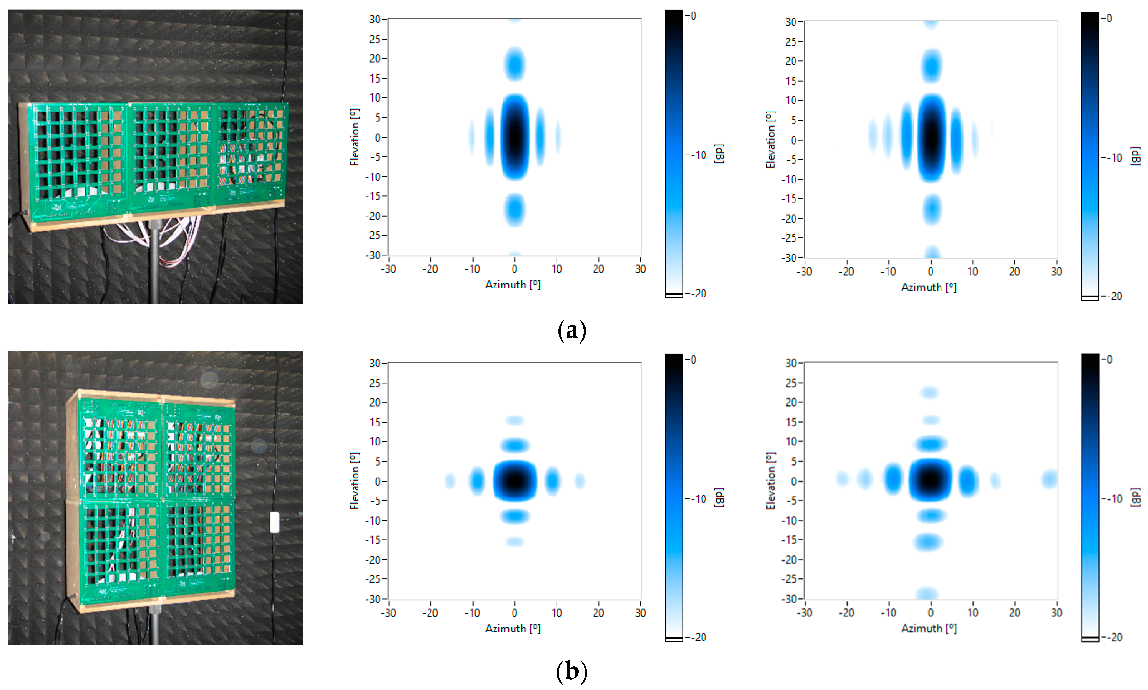
This paper presents in detail the framework of a system that acquires and processes acoustic images. This system is based on a multi-platform framework, where each processing task can be interchanged between the different levels of the framework. Thus, the system can be adapted to different cost and mobility scenarios by means of its reconfigurable framework. The paper also shows the evaluation of processing times of the algorithms involved in obtaining an acoustic image, including signal processing and wideband beamforming via FFT, in each subsystem of the framework. The hardware of the system is based on modules of 8 × 8 square arrays of MEMS microphones, allowing the system to be scalable, by means of the cluster of several modules. This paper also shows the acoustic characterization of the MEMS microphones of the square array, as well as a comparative analysis of the theoretical and measured beam patterns of one of the array modules and of some clusters formed by several array modules.
Section 2 describes the hardware setup of the system and the implemented software algorithms, both defined on the basis of the requirements stated.
Section 3 presents the planar array designed for the system: it introduces MEMS microphones technology and characterizes the frequency response of the microphones used, and it characterizes the array module acoustically, obtaining its beam pattern and also the beam pattern of some clusters of modules. A reconfigurable acquisition and processing framework is proposed in
Section 4, and its performance is analyzed for several scenarios.
Section 5 presents a case study using the system for biometric identification tasks. Finally,
Section 6 contains the conclusions and future research lines.
2. System Description
In this section, the requirements for the implementation of the acquisition and processing system for a 2D array, based on MEMS sensors, are analyzed. Then, the hardware chosen for the implementation is defined, and the processing algorithms to obtain an acoustic image using beamforming techniques are explained.
2.1. Requirements
The size of an acquisition and processing system for an array depends on the number of sensors and the set of processing algorithms. Thus, it is necessary to use a very low-cost technology per channel, in order to build a viable high dimensional array. Using MEMS microphones allows for a cost reduction of two main elements of the system: sensors and acquisition systems. Digital MEMS microphones need only one digital input to be read, although the received digital data must be processed to obtain the waveform signal. Most acquisition systems are based on FPGAs, which have a large number of digital inputs, between 40 and 1400 depending on the model; so, one FPGA can acquire as much channels as the number of digital inputs it contains. Besides, FPGA processing capacity allows the system to carry out simple operations with the acquired signals without increasing costs. The processing capacity of the FPGA is not enough to obtain the final acoustic image so it is necessary that another processor with higher capacity be joined to the FPGA.
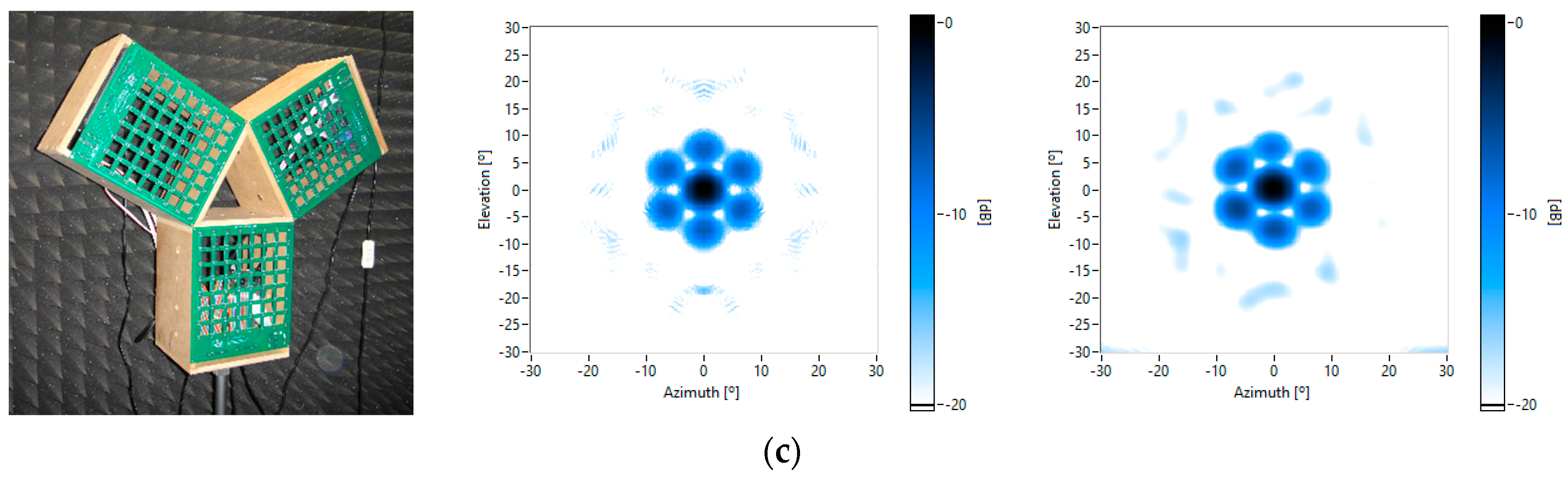
The system must be modular and scalable. Thus, for applications that require a large number of channels, it would only be necessary to add modules of lower dimension instead of designing a new system with higher capacity. In this way, reusing arrays and their processing systems reduces costs. Extra arrays, with their acquisition subsystem, can always be added in order to build higher dimensional systems. The array modules can increase the dimension of the array, but they can also form different kinds of module configurations in order to obtain specific beam patterns, improving the performance of the array, and thus of the complete system. The use of modular subsystems implies the use of a central unit that joins the data from all the modules and controls them.
Finally, the tools and programming languages to be used should also be defined. As this system has different processing platforms, one solution can be the use of a specific language for each platform, but the use of a common programming language on all platforms is desirable.
2.2. Hardware Setup
2.2.1. MEMS Array
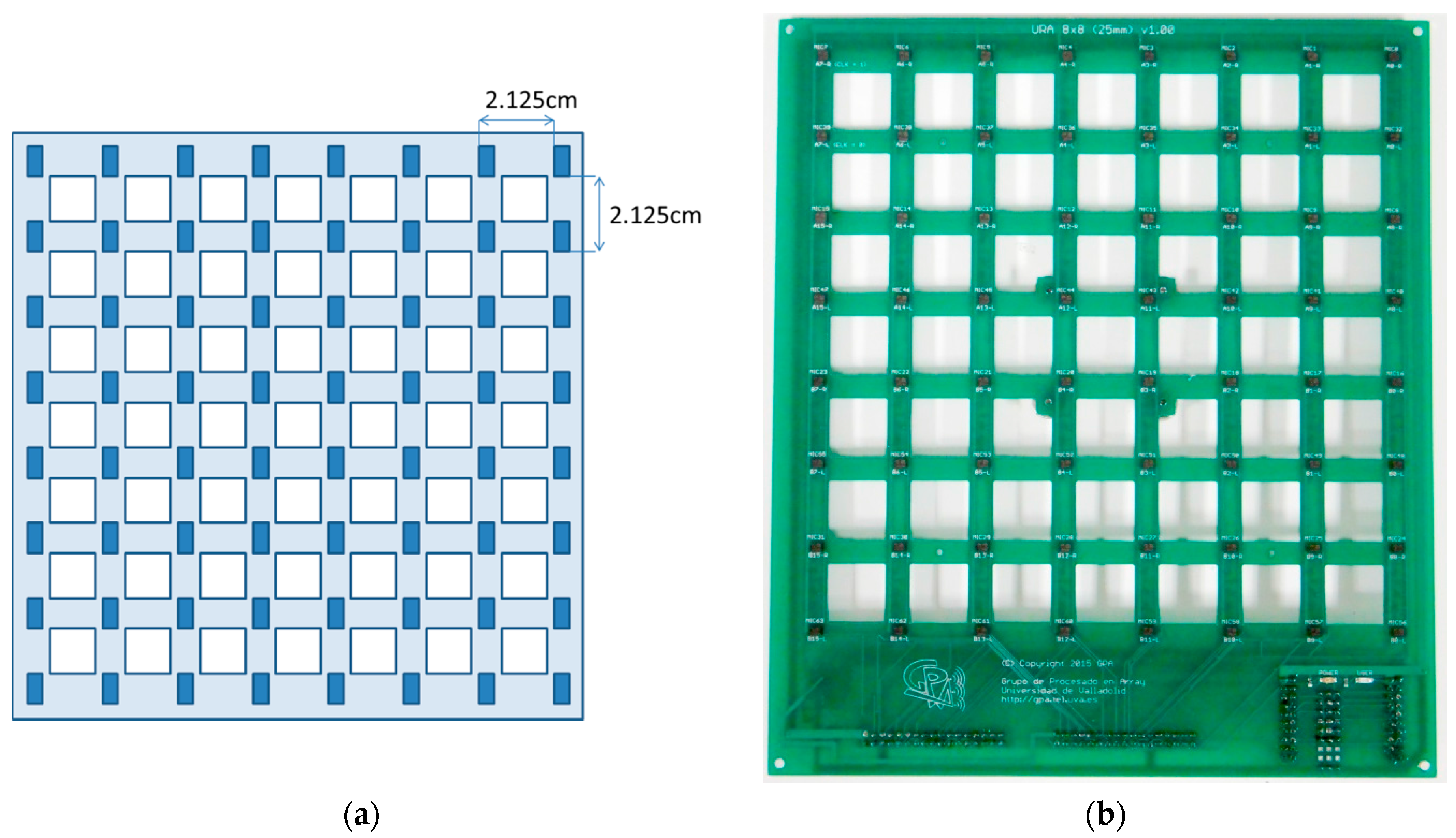
The acoustic images acquisition system shown in this paper is based on a Uniform Planar Array (UPA) of MEMS microphones. This array, which has been entirely developed by the authors, is a square array of 64 (8 × 8) MEMS microphones that are spaced uniformly, every 2.125 cm, in a rectangular Printed Circuit Board (PCB), as shown in
Figure 1. As can also be observed in
Figure 1, the PCB where the MEMS microphones are placed has square gaps between the acoustic sensors, in order to make the array as light and portable as possible.
This array was designed to work in an acoustic frequency range between 4 and 16 kHz. The 2.125 cm spacing corresponds to λ/2 for the 8 kHz frequency. This spacing allows a good resolution for low frequencies, while avoiding grating lobes for high frequencies in the angular exploration zone of interest [
10].
For the implementation of the array, MP34DT01 microphones of STMicroelectronics were chosen. They are digital MEMS microphones with a PDM (Pulse Density Modulation) interface and with a one-bit digital signal output, obtained using a high sampling rate (1 MHz to 3.25 MHz) [
24,
25,
26]. The main features of these microphones are: low-power, omnidirectional response, 63 dB SNR, high sensitivity (−26 dB FS) and an almost flat frequency response (±6 dB in the range of 20 Hz to 20 kHz).
2.2.2. Processing System
Taken into account the previous requirements, the hardware used to implement the system was selected. The design of a specific hardware was rejected due to the high cost of the design and the required time, so a search for a commercial solution was done.
MyRIO platform [
27] has been selected as the base unit for this system. This platform belongs to the Reconfigurable Input-Output (RIO) family of devices from National Instruments that is oriented to sensors with nonstandard acquisition procedures, allowing low-level programming of the acquisition routines. Specifically, myRIO platform is an embedded hardware based on a Xilinx Zynq 7010 chip, which incorporates a FPGA and a dual-core ARM
® Cortex™-A9 processor. The FPGA has 40 lines of digital input/output, 32 of which are used as the connection interface with the 64 MEMS microphones of the array, multiplexing two microphones in each I/O line; while the other eight lines are used to clock generation and synchronization. The ARM processor is equipped with 256 MB of DDR3 RAM, 512 MB of built-in storage space, USB Host port, and Wi-Fi interface. All this hardware is enclosed in a small box (136 × 89 × 25 mm) that costs about $1,000.
The embedded processor included in myRIO is capable of running all the software algorithms to generate acoustic images, so it can be used as a standalone array module formed by a myRIO connected to a MEMS array board as shown in
Figure 2. The acoustic images can be stored in the internal storage of myRIO or in an external disk connected through the USB port.
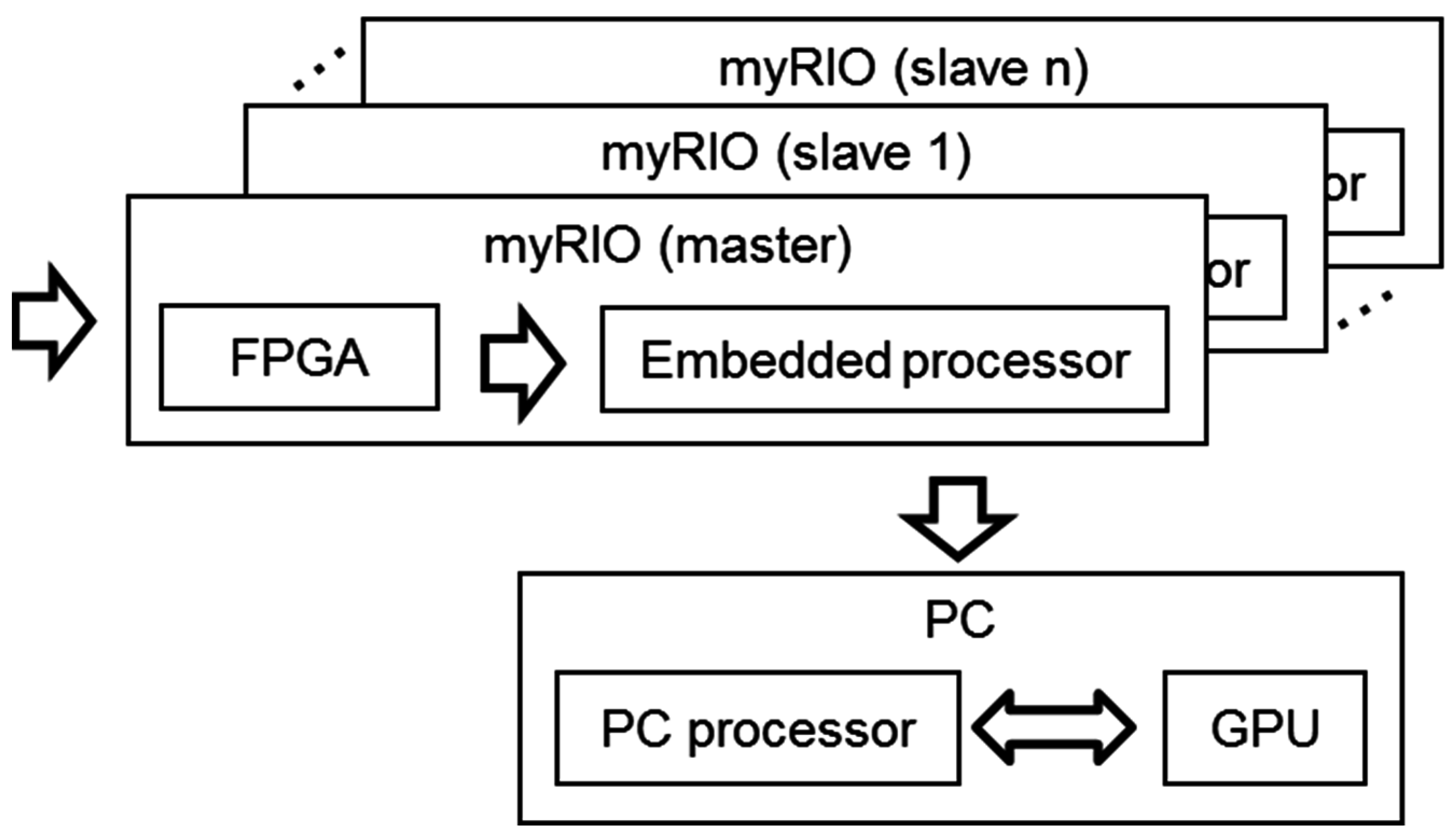
Although myRIO can work as a standalone system, the lack of display means that it is usually controlled from a PC connected using a Wi-Fi interface. In a global hardware setup, as shown in
Figure 3, the system includes a PC and one or more array modules. The PC performs three main functions:
As user interface, the PC allows changing the system parameters and visualizing the acoustic images.
As processing unit, the processors inside the PC could be used to execute the algorithms in order to obtain the acoustic images faster. Two processors are available in the PC: a general-purpose PC processor and a Graphical Processing Unit (GPU) included in the graphics card.
As a control unit, a single PC can manage several myRIO platforms, each one associated to an array module. This feature allows clustering several modules for a proper operation of the system, which are synchronized between them using their I/O lines, where one myRIO is the master and the others are slaves.
2.3. Software Algorithms
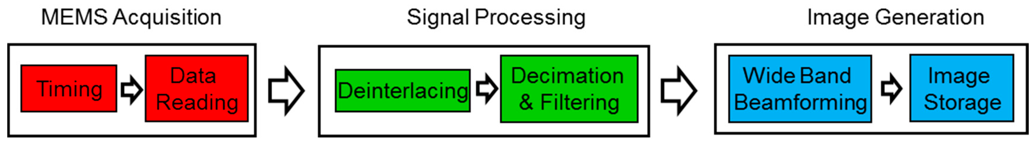
The algorithms implemented in the system, shown in
Figure 4, can be divided into three blocks: MEMS acquisition, signal processing, and image generation.
The programming language used is LabVIEW 2015, along with its Real Time, FPGA, and GPU modules, which allows developing applications on different hardware platforms like those used in the system: FPGA, Embedded Processor (EP), PC, and GPU. In addition, most of the developed algorithms can run on any of the platforms without reprogramming.
In the acquisition block, each MEMS microphone with a PDM interface, which internally incorporates a one-bit sigma-delta converter with a sampling frequency of 2 MHz, performs signal acquisition. So, each acquired signal is coded with only one bit per sample. This block is implemented in the FPGA, generating a common clock signal for all MEMS, and reading simultaneously 64 sensors signals via the digital inputs of the FPGA. These signals are stored in 64-bit binary words, where each bit stores the signal of each MEMS. Thus, the size of the data is minimal and the transfer rate is high.
In the signal processing block two routines are implemented: (i) Deinterlacing: Through this process, 64 one-bit signals are extracted from each binary word and (ii) Decimate & Filtering: Applying downsampling techniques, based on decimation and filtering [
25], 64 independent signals are obtained and the sampling frequency is reduced from 2 MHz to 50 kHz.
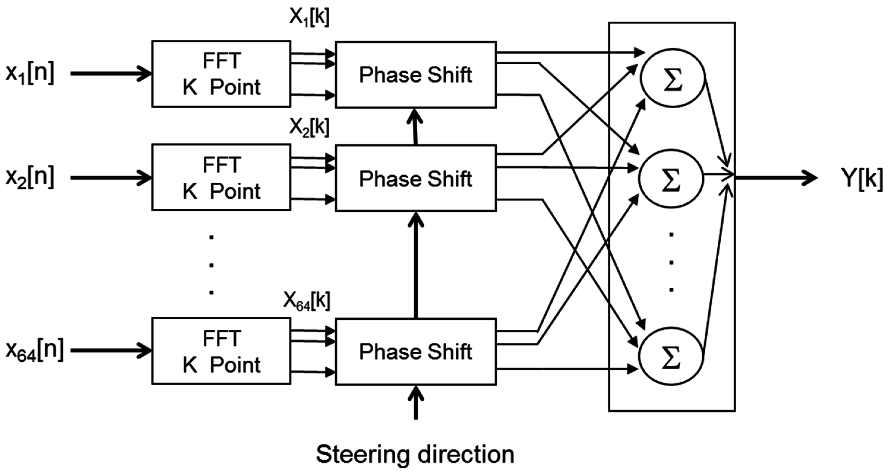
Finally, in the image generation block, based on wideband beamforming, a set of N × N steering directions are defined, and the beam former output are assessed for each of these steering directions. Wideband beamforming [
3] computes the FFT of the MEMS signals x
i[n]; multiplies, element by element, each FFT X
i[k] by a phase vector, that depends on the steering direction and the sensor position; and finally takes the sum of the FFT shifted in phase, as shown in
Figure 5. The images generated are then displayed and stored in the system.
4. Multiplatform Processing Framework
On the basis of the global hardware setup presented in
Section 2, a multiplatform framework with four processing levels, each one implemented over a hardware platform, was defined. These processing levels are:
Level 1 (L1) corresponds to the FPGA based on its capacity to carry out simple tasks of filtering and decimation. The parallelization degree is maximum and limited by the number of the FPGA resources (Look Up Tables, multipliers, DSP units, RAMs, etc.).
Level 2 (L2) is based on an Embedded Processor (EP), such as an ARM processor that picks up the FPGA signals and carries out the first processing stages. It has limited memory as well as processing and storage capacity.
Level 3 (L3) is based on a PC processor, such as an Intel Core i5/i7 with two to four cores. It is in charge of the main processing of the application, with medium cost and consumption. It has a high processing capacity, a great amount of memory (up to 64 Gb) and storage capacity based on a disk.
Level 4 (L4) is formed by coprocessors, which can carry out massive FFT and lineal algebra operations, such as a Graphical Processing Unit (GPU), and they have from 200 to 1200 cores.
Processing time, parallelization degree and required memory must be analyzed for all the algorithms, needed to obtain an acoustic image, described in
Section 2. The objective of this analysis is to determine the platforms/levels where these algorithms can be implemented, and the optimal distribution between the available algorithms and platforms.
The time required to transfer data between levels should also be taken into account. This transfer time, in many situations, can be similar to, or even greater than the algorithm processing time. Ideally, these transfers should be minimized, in order to process data on the same level and work with a one-way processing flow, i.e., the FPGA sends data to the EP, and it sends its data to the PC. When one level is used as a coprocessor, bidirectional flows are established, i.e., between the EP and the PC processor, through a TCP-IP interface, or between the PC processor and the GPU, using a PCIe interface.
4.1. Analysis Settings
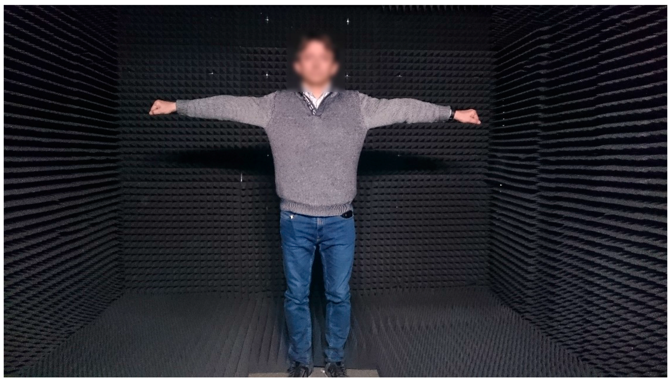
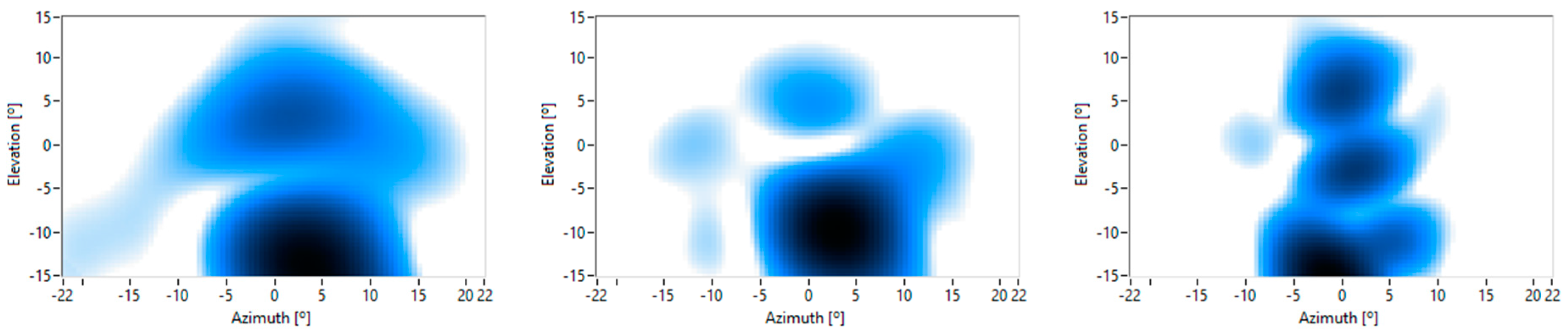
In order to analyze the performance of the algorithms in each level, a work scheme, based on an active acoustic system, was defined. This system sends a multifrequency acoustic signal that reaches the person under test and then, the reflected signal is collected by the MEMS array. Finally, a multichannel signal is processed following the block diagram shown in
Figure 11.
There are hardware constrains that make the implementation of some algorithms in every processing level unfeasible, i.e., MEMS acquisition can only be carried out in the FPGA, or image storage cannot be executed either in the FPGA or in the GPU.
Table 1 shows the main algorithms used and the processing levels where they could be implemented.
The performance measurements have been carried out using the global hardware setup, with one array module, controlled by a PC. The selected PC is based on an i5 processor with four cores and 32 GB RAM, including a NVIDIA GTX 660 card with 960 cores. As algorithm parameters, an acquisition time of 30 ms, 256-point FFTs, and a grid of 40 × 40 steering directions have been assumed.
4.2. Performance Analysis
4.2.1. Signal Processing
The time required to implement each of the algorithms included in the signal processing on the different levels are presented in
Table 2.
Level 1 allows the implementation of all these algorithms using FPGA hardware resources, simultaneously with capture and signal processing without consuming additional processing time. Analyzing data from Levels 2 and 3, it can be observed that PC processing time is about 20 times lower than the time required by the EP. The times on Level 3 can be increased by transferring time from the EP to the PC for further processing. This transfer time was measured and its value is about 113 ms. Level 4, based on GPUs, was discarded because the algorithms required to perform deinterlacing and decimation/filtering are not available for this platform in LabVIEW.
4.2.2. Image Generation
Table 3 shows the required processing times related with wideband beamforming and transfer times between the PC and the GPU, for the generation of an acoustic image.
Level 1 is discarded due to the fact that (i) the FPGA included in myRIO does not have enough memory to generate and store images; and (ii) the implementation of the beamforming algorithms requires FPGAs with a large number of slices which makes it more costly. Processing times on Level 2 are the longest and the memory capacity of the EP is limited, therefore, this level is also discarded.
In order to compare Levels 3 and 4, transfer times between the PC and the GPU should be considered. The results in
Table 3 show that it is preferable to perform the beamforming on the PC. These results might seem contradictory, since the processing power of the GPU is higher than the PC’s. This is due to the following: (i) for 64 sensors, the GPU capacity of parallel processing is not totally used; and (ii) libraries included in LabVIEW-GPU are limited, which forces multiple data transfers between PC and GPU memories. The implementation of the beamforming algorithm in native code for the GPU and its subsequent invocation from LabVIEW would significantly reduce the overall processing time.
If the number of sensors of the system increases, by adding multiple modules of 64 sensors, the performed operations increase proportionately, taking advantage of the whole capacity of GPU parallel processing. In
Table 4, the processing and transfer times versus the number of sensors is analyzed. If the number of sensors is larger than 128, GPU performance improves.
Image storage can be implemented in Levels 2 and 3 because embedded microprocessors and PCs have the capacity to store data. Embedded systems incorporate a low capacity internal disk and can use external high-capacity USB drives/disks. In the case of PCs, they include both high-capacity internal and external hard drives. As storage times are very dependent of the type and model of the used media, they were discarded for the analysis.
4.3. Framework Proposals
Depending on the level where the signal processing algorithm runs, there are three implementation options. In turn, for each of these possibilities, there are up to three options depending on where the wideband beamforming algorithm is implemented.
Table 5 summarizes the different options to implement the acoustic imaging algorithms with their corresponding processing and transfer times for all feasible processing levels.
The frameworks that are based on the implementation of the signal processing algorithms through an embedded processor or a PC (grey columns) are discarded, as the FPGA allows the parallel implementation of the capture and signal processing. Thus, only three framework proposals (white columns) have been considered, associating each one to a particular use:
- (1)
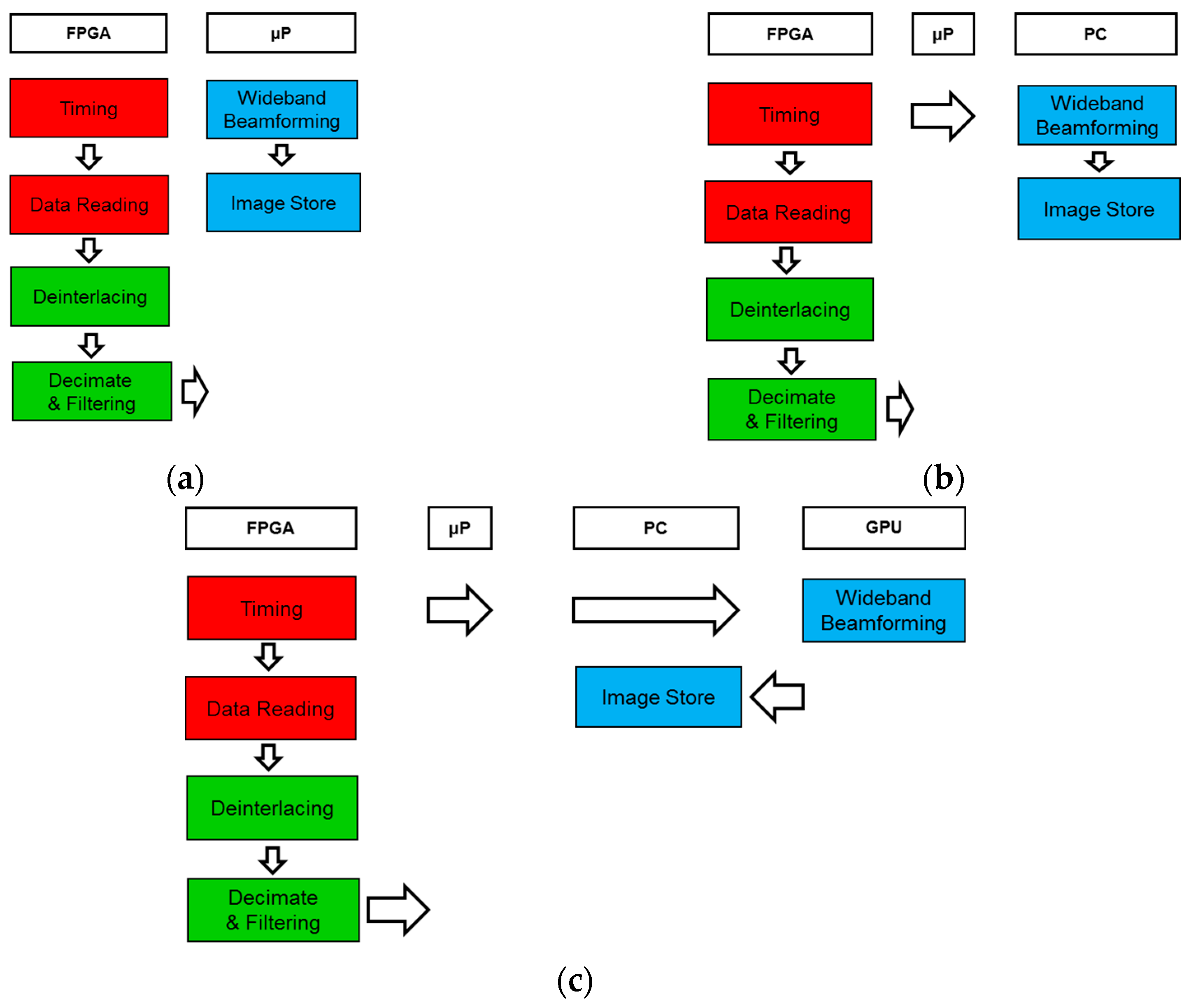
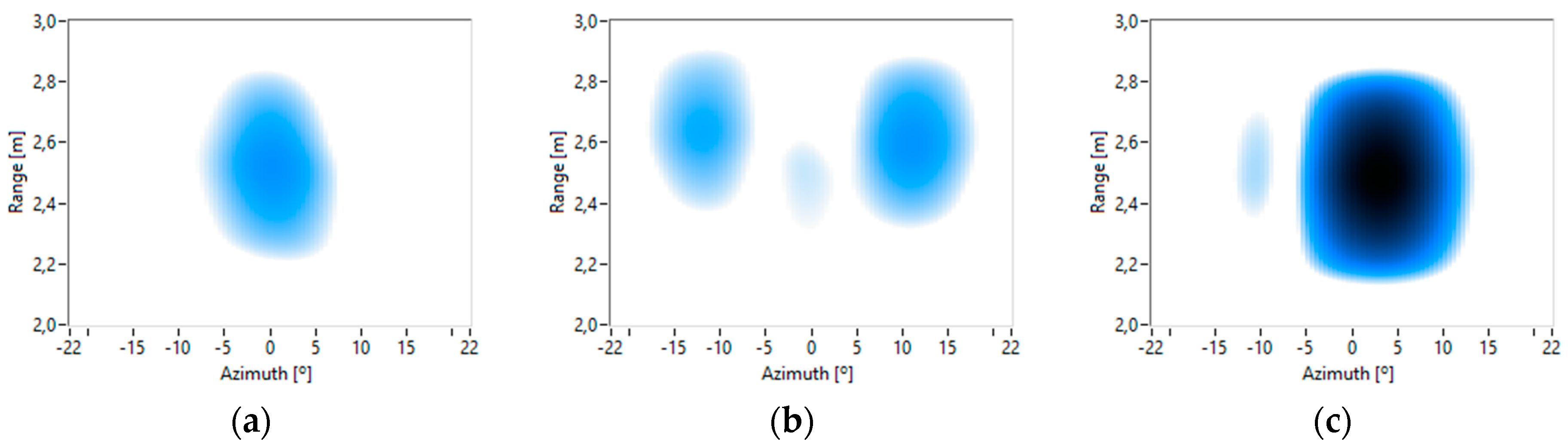
Embedded system: The whole processing takes place in the embedded processor/FPGA without a PC, as shown in
Figure 12a. This framework is optimal for applications that require portable systems and where the processing speed is not critical.
- (2)
PC system: The processing is shared between the FPGA and the PC. The embedded processor is used to control and transfer data between the PC and FPGA, as shown in
Figure 12b. This framework presents the lowest processing time using 64 sensors. It is optimal for systems that require a short response time and/or a small number of sensors.
- (3)
PC system with GPU: The algorithms are implemented in the same way as in the previous framework excluding beamforming, which is implemented on the GPU, as shown in
Figure 12c. This framework improves processing time as the number of sensors increases. It is the most versatile framework and it is optimal for systems that require a large number of sensors.
6. Conclusions
A modular, scalable, multiplatform, and low-cost acquisition and processing system was designed to obtain acoustic 3D images. This system is based on a module with a myRIO platform and a planar array that consists of 64 MEMS microphones uniformly distributed on an 8 × 8 grid. The system can work with only one module or with a cluster of several of them, using the same PC unit. The system can be adapted to different cost and mobility scenarios, by means of its reconfigurable multi-platform framework, where each processing tasks can be interchanged between its different levels.
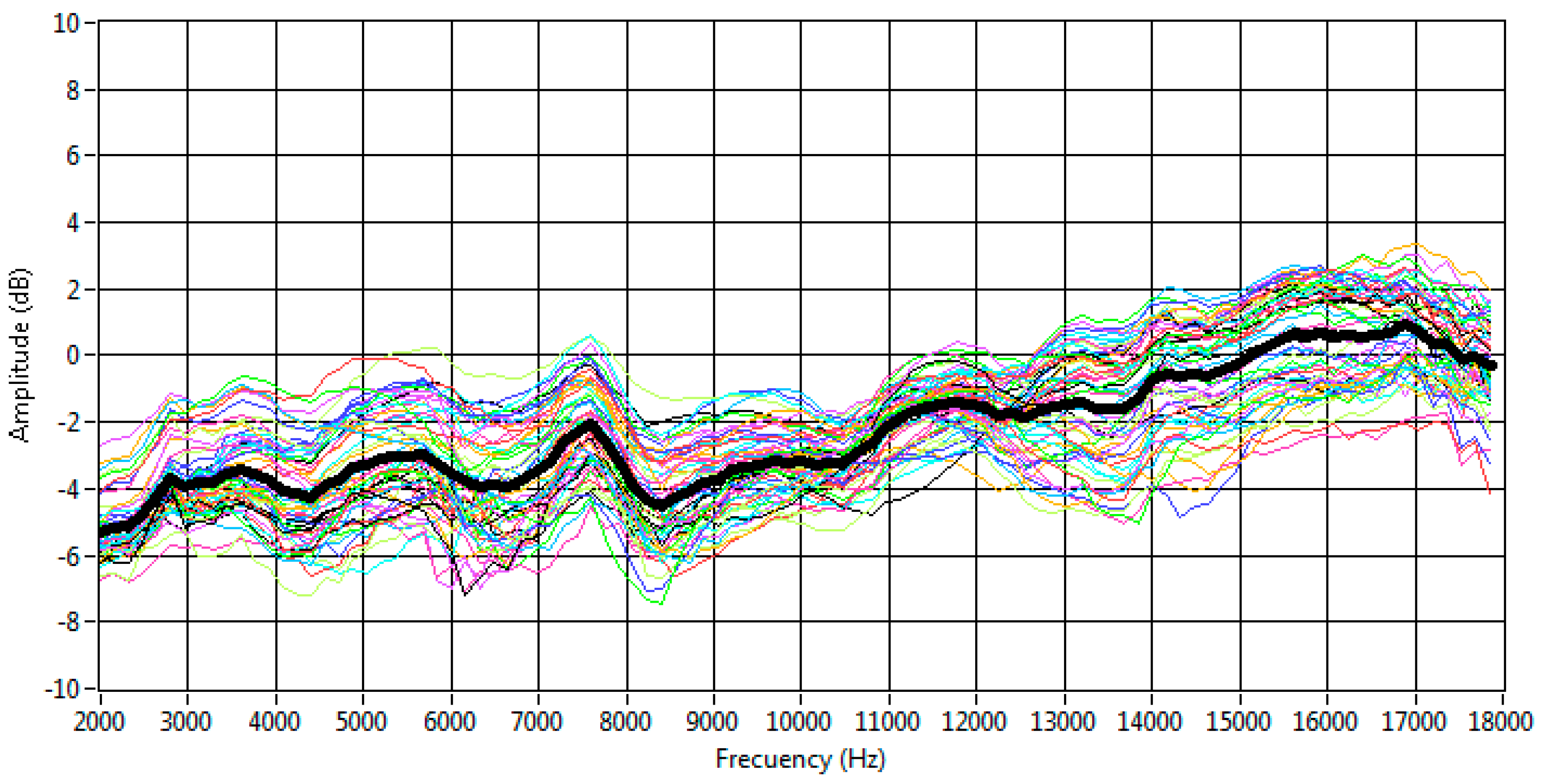
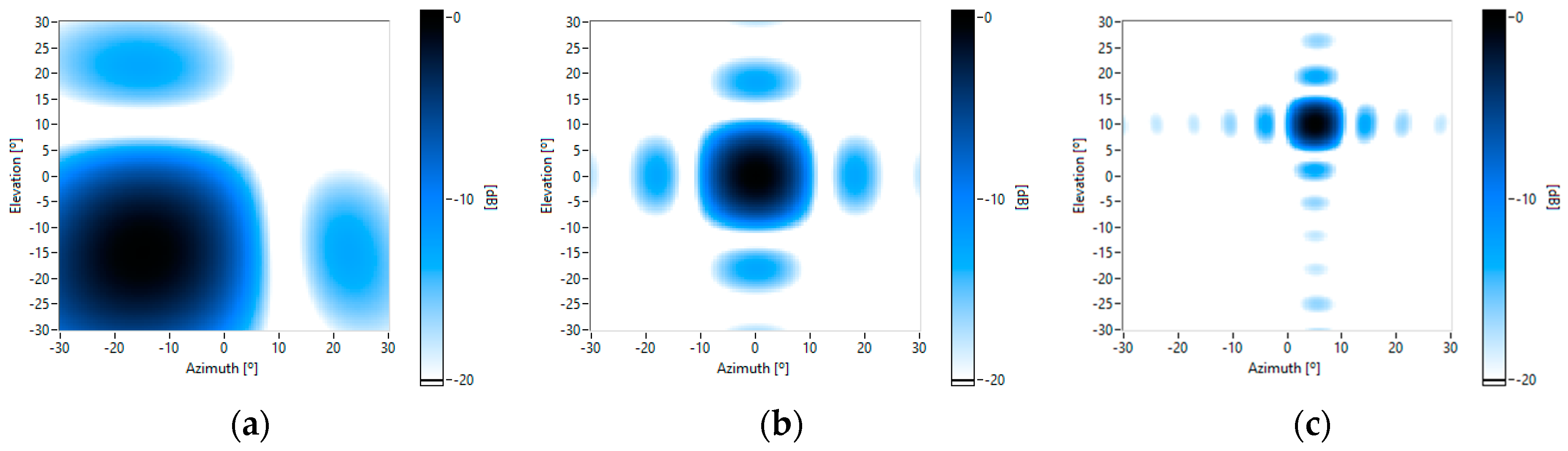
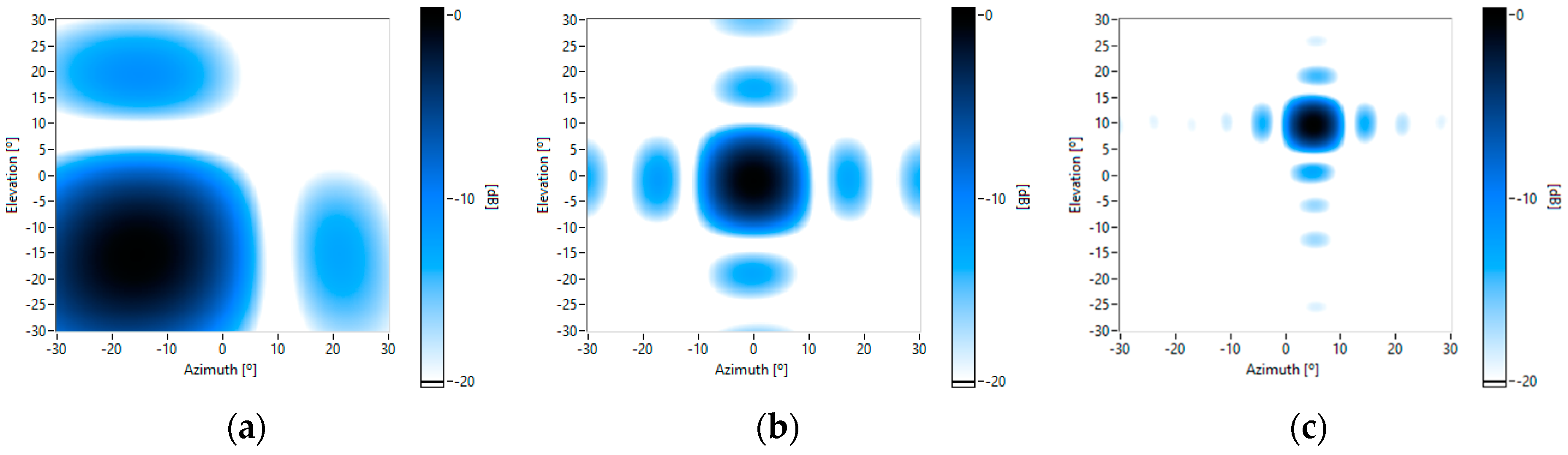
A digital MEMS microphone was selected as the acoustic sensor. This microphone allows the integration of a large number of sensors on a small sized board at low cost. An analysis of the frequency responses of these 64 MEMS microphones was carried out, obtaining: (i) a flat average response in the acoustic band, with a variation of ±3 dB; and (ii) dispersion between the responses lower than ±2 dB. The beampatterns of an array module and of different clusters of modules were also characterized, verifying that they indeed fit the theoretical models, so it is not necessary to calibrate the array.
Finally, a multiplatform framework and the necessary algorithms to obtain acoustic images from the data captured by each microphone were jointly defined. The processing time of the algorithms was evaluated on each platform. Based on these results, three different frameworks were defined for specific uses.
Thus, a versatile system for different applications, due to its modularity, scalability and reconfigurability, was designed to obtain acoustic images. Currently, the authors are using the system in the field of biometric identification, working on feature extraction and person identification from acoustic images.


