
Underwater Imaging Using a 1 × 16 CMUT Linear Array

 ,
, 
Abstract
:1. Introduction
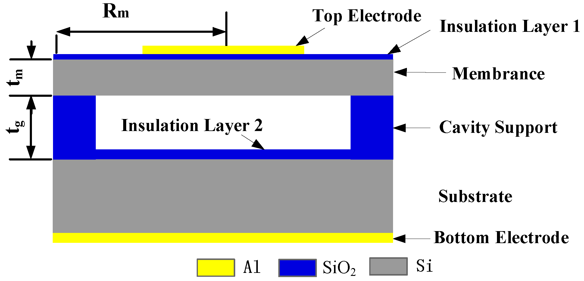
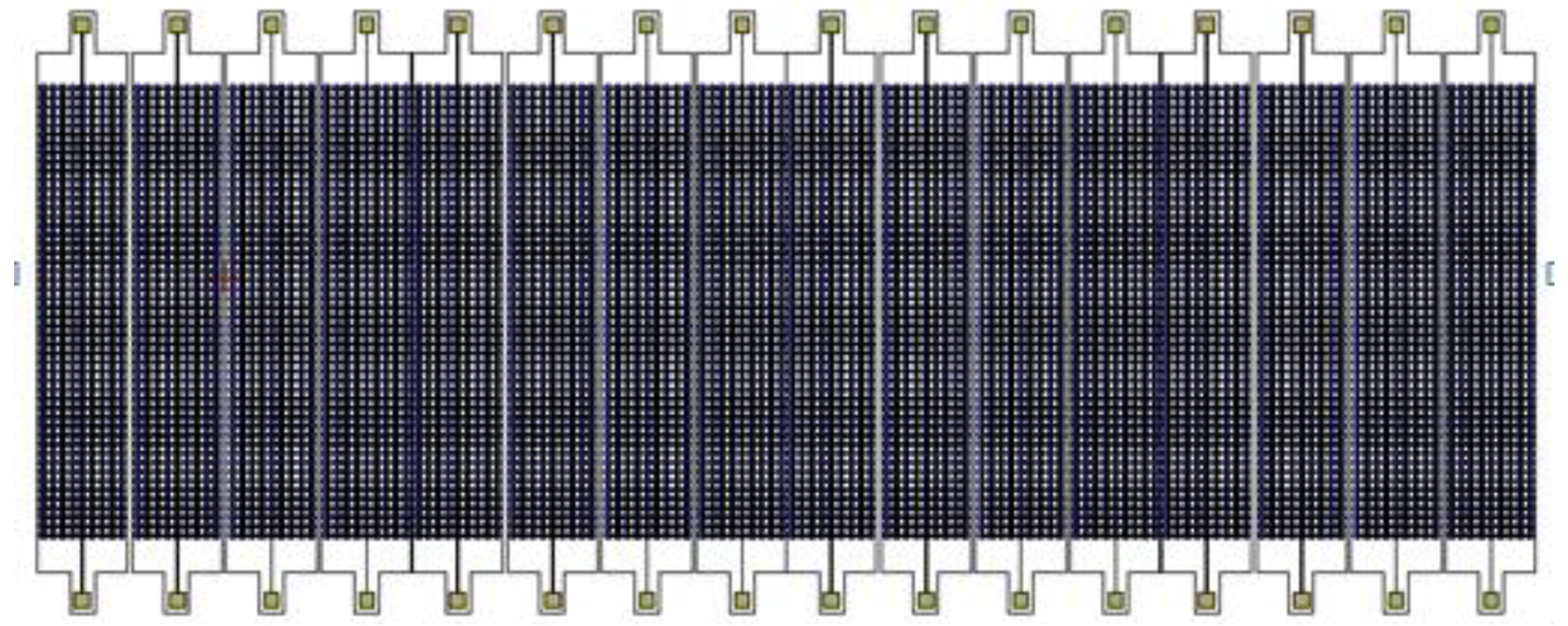
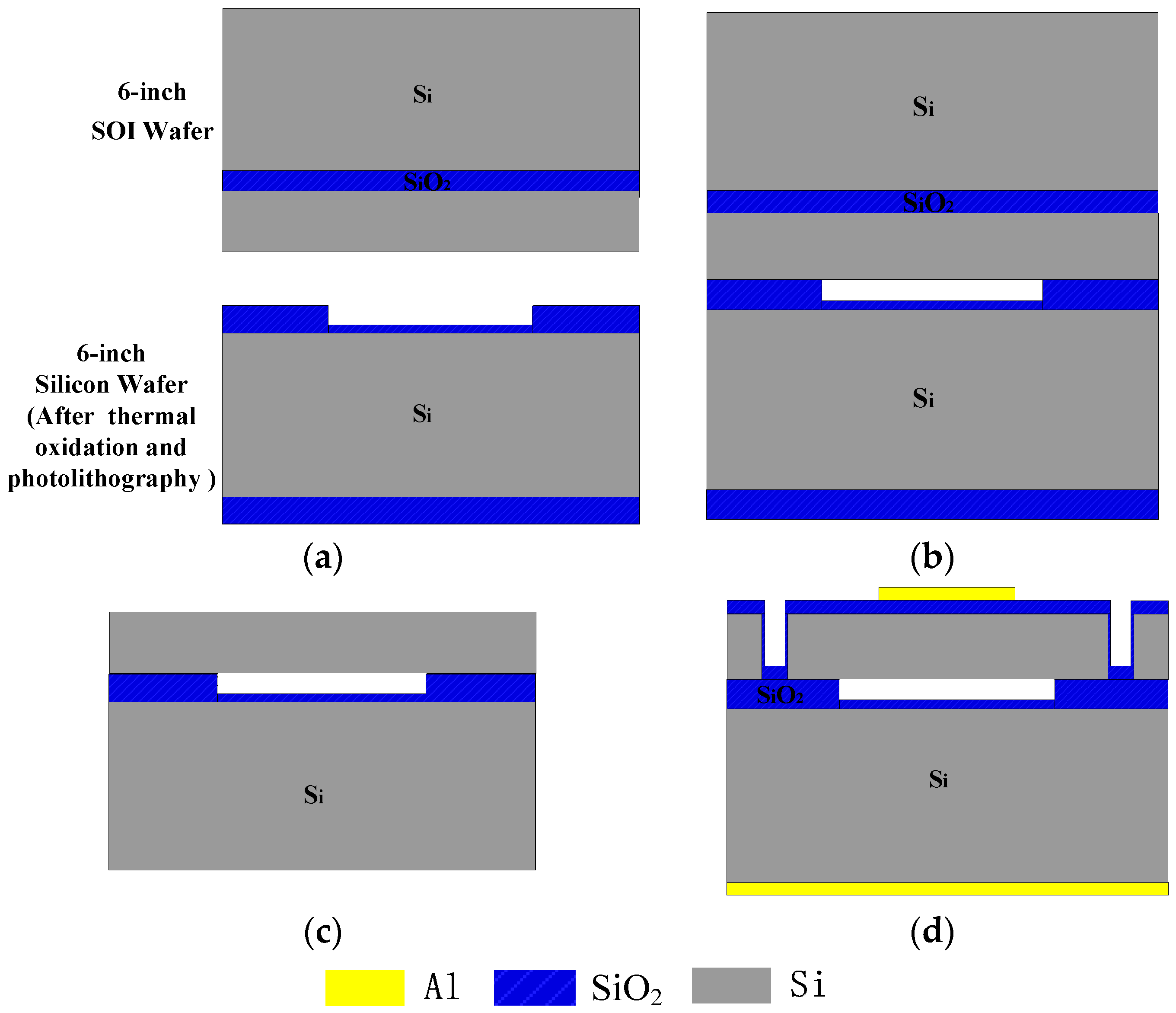
2. Structural Design
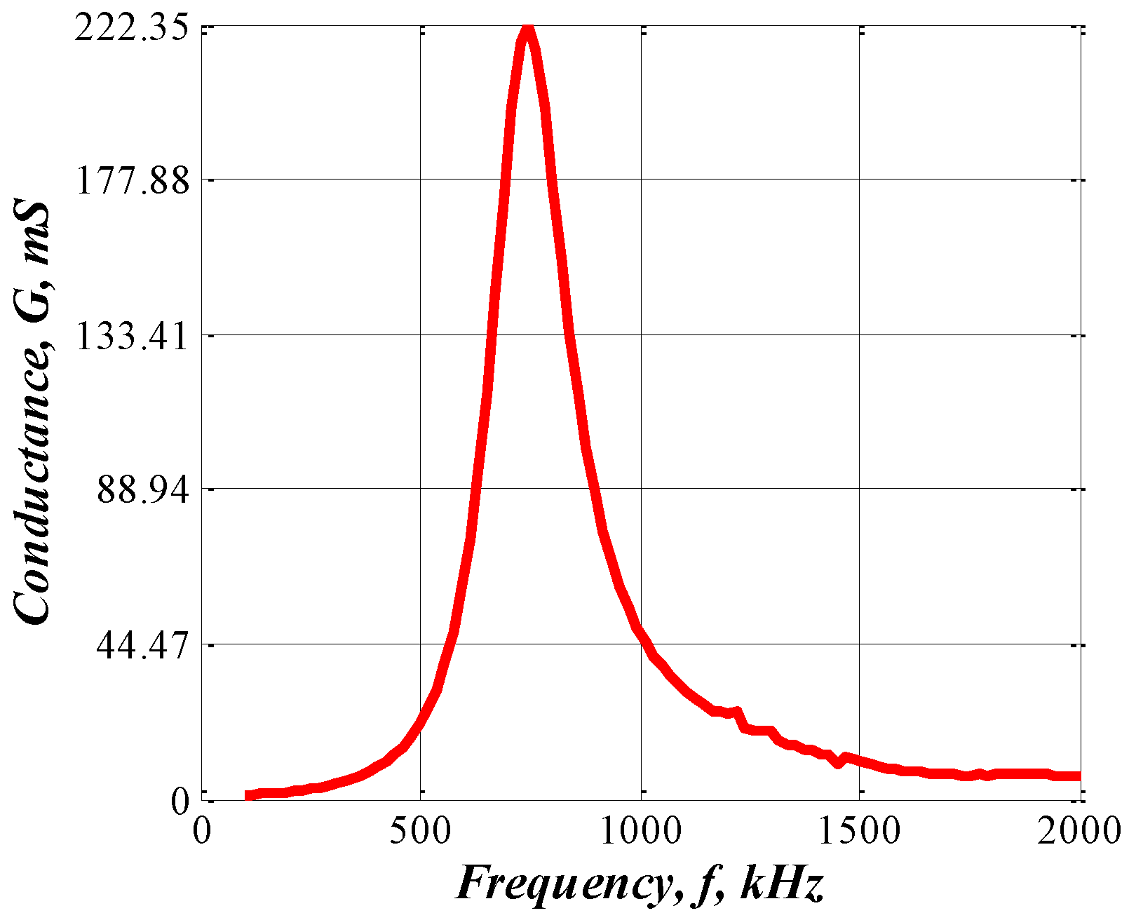
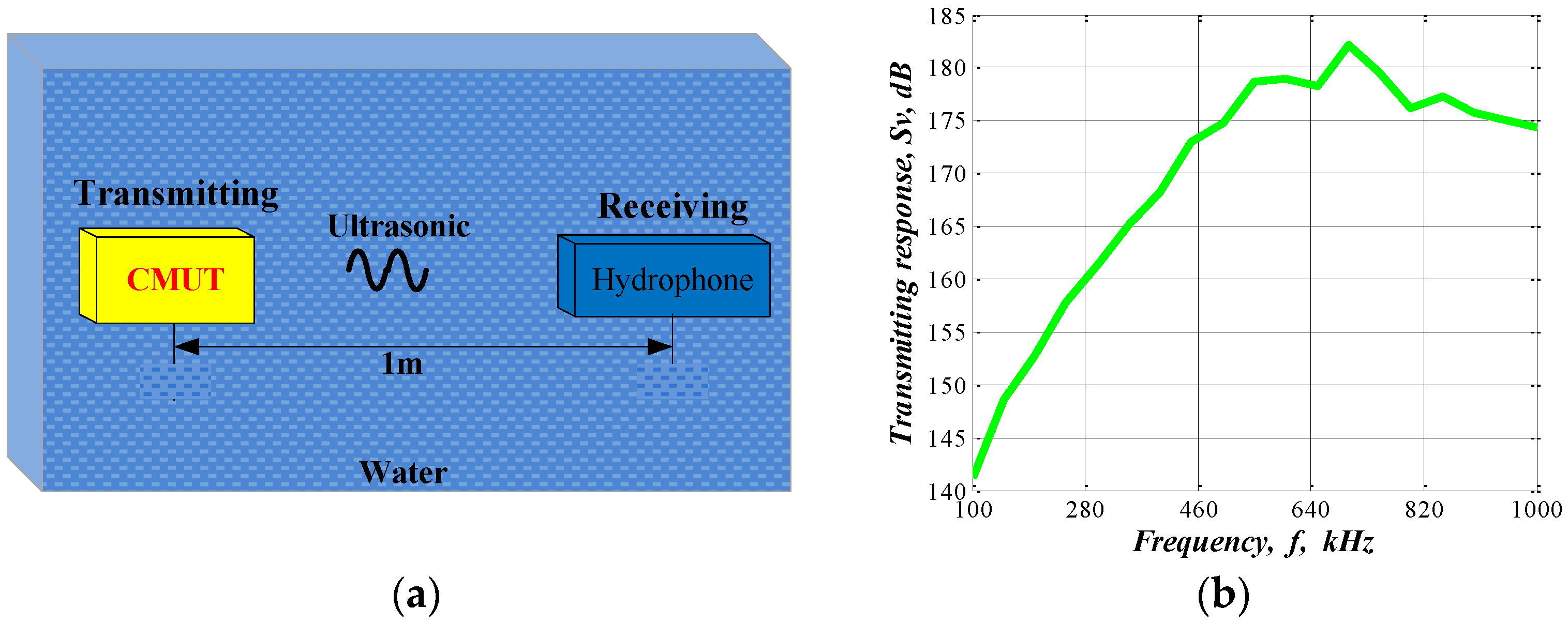
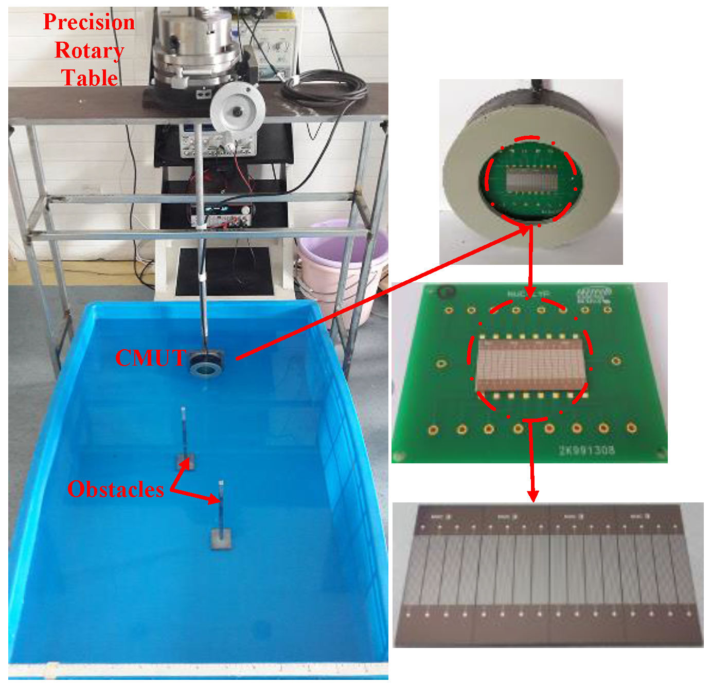
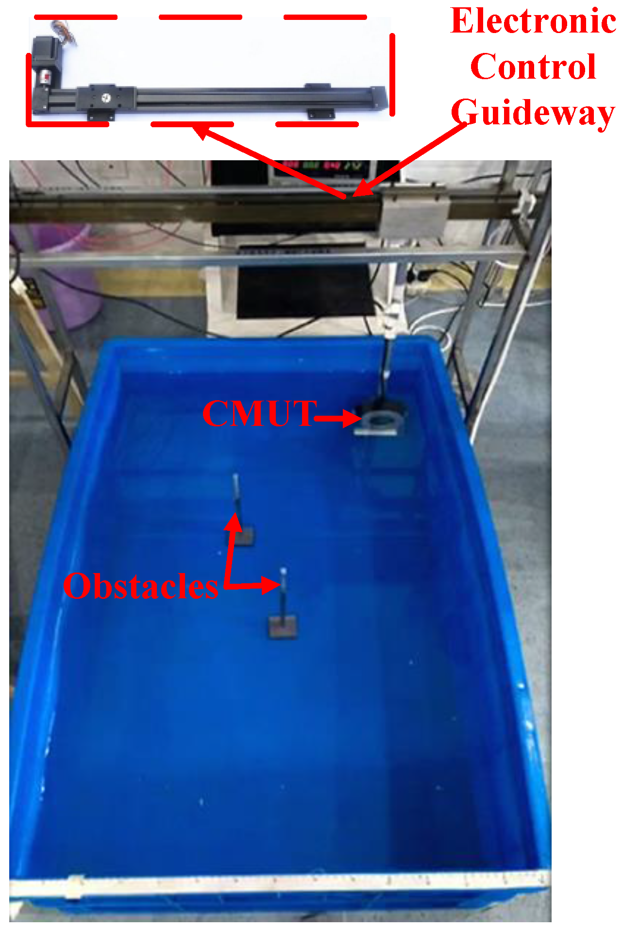
3. Underwater Experimental
- (1)
- (2)
- (3)
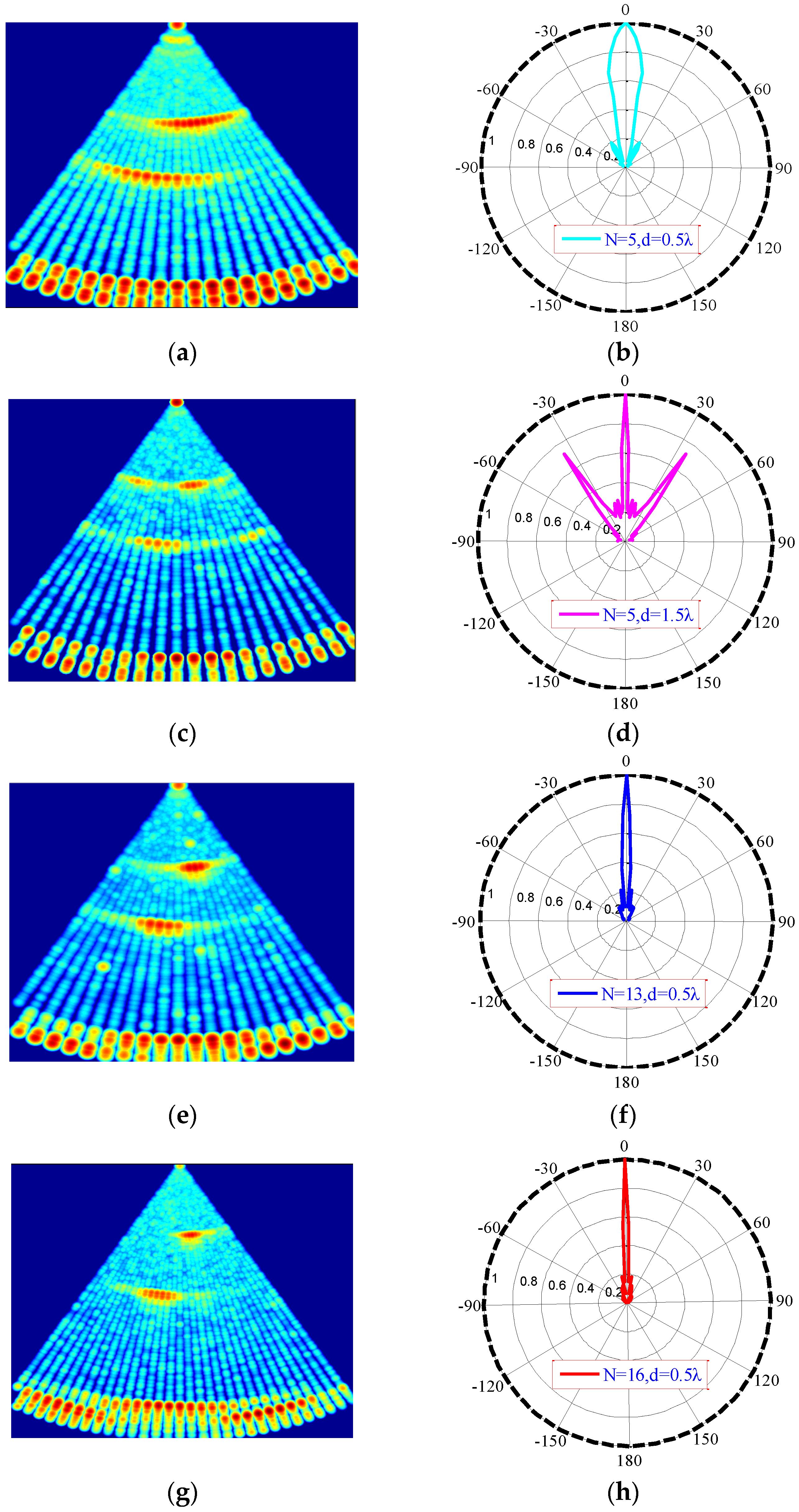
4. Imaging
5. Conclusions
Acknowledgments
Author Contributions
Conflicts of Interest
References
- Caronti, A.; Caliano, G.; Carotenuto, R.; Savoia, A.; Pappalardo, M.; Cianci, E.; Foglietti, V. Capacitive micromachined ultrasonic transducer (CMUT) arrays for medical imaging. Microelectron. J. 2006, 37, 770–777. [Google Scholar] [CrossRef]
- Oralkan, O.; Ergun, A.S.; Johnson, J.A.; Karaman, M.; Demirci, U.; Kaviani, K.; Lee, T.H.; Khuri-Yakub, B.T. Capacitive micromachined ultrasonic transducers: Next-generation arrays for acoustic imaging? IEEE Trans. Ultrason. Ferroelectr. Freq. Control 2002, 49, 1596–1610. [Google Scholar] [CrossRef] [PubMed]
- Choe, J.W.; Oralkan, O.; Nikoozadeh, A.; Gencel, M.; Stephens, D.N.; O'Donnell, M.; Sahn, D.J.; Khuri-Yakub, B.T. Volumetric Real-Time Imaging Using a CMUT Ring Array. IEEE Trans. Ultrason. Ferroelectr. Freq. Control 2012, 59, 1201–1211. [Google Scholar] [CrossRef] [PubMed]
- Emadi, T.A.; Buchanan, D.A. A novel 6 × 6 element MEMS capacitive ultrasonic transducer with multiple moving membranes for high performance imaging applications. Sens. Actuators A Phys. 2015, 222, 309–313. [Google Scholar] [CrossRef]
- Chang, C.; Moini, A.; Nikoozadeh, A.; Sarioglu, A.F.; Apte, N.; Zhuang, X.; Khuri-Yakub, B.T. Singulation for imaging ring arrays of capacitive micromachined ultrasonic transducers. J. Micromech. Microeng. 2014, 24, 10700210. [Google Scholar] [CrossRef]
- Wang, H.; Wang, X.; He, C.; Xue, C. Design and Performance Analysis of Capacitive Micromachined Ultrasonic Transducer Linear Array. Micromachines 2014, 5, 420–431. [Google Scholar] [CrossRef]
- Ladabaum, I.; Jin, X.; Soh, H.T.; Atalar, A.; Khuri-Yakub, B.T. Surface micromachined capacitive ultrasonic transducers. IEEE Trans. Ultrason. Ferroelectr. Freq. Control 1998, 45, 678–690. [Google Scholar] [CrossRef] [PubMed] [Green Version]
- Emadi, T.A.; Buchanan, D.A. Multiple Moving Membrane CMUT with Enlarged Membrane Displacement and Low Pull-Down Voltage. IEEE Electron Device Lett. 2013, 34, 1578–1580. [Google Scholar] [CrossRef]
- Jeong, B.; Kim, D.; Hong, S. Performance and reliability of new CMUT design with improved efficiency. Sens. Actuators A Phys. 2013, 199, 325–333. [Google Scholar] [CrossRef]
- Ergun, A.S.; Yaralioslu, G.G.; Khuri-Yakub, B.T. Capacitive micromachined ultrasonic Transducers: Theory and technology. J. Aerosp. Eng. 2003, 16, 76–84. [Google Scholar] [CrossRef]
- Mills, D.M.; Smith, L.S. Real Time in vivo Imaging with Capacitive Micromachined Ultrasonic Transducer (CMUT) Linear Arrays. In Proceedings of the 2003 IEEE Ultrasonic Symposium, Honolulu, HA, USA, 5–8 October 2003; pp. 568–571.
- Eccardt, P.C.; Niederer, K.; Fischer, B. Micromachined Transducers for Ultrasonic Applications. In Proceedings of the 1997 IEEE Ultrasonic Symposium, Toronto, ON, Canada, 5–8 October 1997.
- Roh, Y.; Khuri-Yakub, B.T. Finite element analysis of underwater capacitor micromachined ultrasonic transducers. IEEE Trans. Ultrason. Ferroelectr. Freq. Control 2002, 49, 293–298. [Google Scholar] [CrossRef] [PubMed]
- Liu, C.; Chen, P. Surface micromachined capacitive ultrasonic transducer for underwater imaging. J. Chin. Inst. Eng. 2007, 30, 447–458. [Google Scholar] [CrossRef]
- Cheng, X.; Chen, J.; Li, C.; Liu, J.; Shen, I.; Li, P. A Miniature Capacitive Ultrasonic Imager Array. IEEE Sens. J. 2009, 9, 569–577. [Google Scholar] [CrossRef]
- Doody, C.B.; Cheng, X.; Rich, C.A.; Lemmerhirt, D.F.; White, R.D. Modeling and Characterization of CMOS-Fabricated Capacitive Micromachined Ultrasound Transducers. J. Microelectromech. Syst. 2011, 20, 104–118. [Google Scholar] [CrossRef]
- Peake, W.H.; Thurston, E.G. The lowest resonant frequency of a water-loaded circular plate. Acoust. Soc. Am. 1954, 26, 166–168. [Google Scholar] [CrossRef]
- Wong, A.C. VHF Microelectromechanical Mixer-Filters. Ph.D. Thesis, The University of Michigan, Ann Arbor, MI, USA, 2001. [Google Scholar]
- Shen, W.; Miao, J.; Xiong, J.; He, C.; Xue, C. Micro-electro-mechanical systems capacitive ultrasonic transducer with a higher electromechanical coupling coefficient. IET Micro Nano Lett. 2015, 10, 541–544. [Google Scholar]
- Li, Y.P.; He, C.D.; Zhang, J.T.; Song, J.L.; Zhang, W.D.; Xue, C.Y. Design and analysis of Capacitive Micromachined Ultrasonic Transducer based on SU-8. Key Eng. Mater. 2014, 645–646, 577–582. [Google Scholar] [CrossRef]
- Zhang, R.; Zhang, W.D.; He, C.D.; Song, J.L.; Mu, L.F.; Cui, J.; Zhang, Y.M.; Xue, C.Y. Design of Capacitive Micromachined Ultrasonic Transducer (CMUT) linear array for underwater imaging. Sens. Rev. 2015, 36, 77–85. [Google Scholar] [CrossRef]
- Song, J.L.; Xue, C.Y.; He, C.D.; Zhang, R.; Mu, L.F.; Cui, J.; Miao, J.; Liu, Y.; Zhang, W.D. Capacitive Micromachined Ultrasonic Transducers (CMUTs) for Underwater Imaging Applications. Sensors 2015, 15, 23205–23217. [Google Scholar] [CrossRef] [PubMed]
- Zhang, R.; Xue, C.Y.; He, C.D.; Zhang, Y.M.; Song, J.L.; Zhang, W.D. Design and performance analysis of capacitive micromachined ultrasonic transducer (CMUT) array for underwater imaging. Microsyst. Technol. 2015. [Google Scholar] [CrossRef]
- Zheng, S.J.; Yuan, W.J.; Miu, R.X.; Xue, Y.Q. Underwater Acoustic Measurement Testing Technology; Harbin Engineering University Press: Harbin, China, 1995; pp. 223–232. [Google Scholar]
- Neild, A.; Hutchins, D.A.; Billson, D.R. Imaging using air-coupled polymer-membrane capacitive ultrasonic arrays. Ultrasonics 2004, 42, 859–864. [Google Scholar]
- Guarneri, G.A.; Pipa, D.R.; Junior, F.N.; Valéria, L.; de Arruda, R.; Victor, M.; Zibetti, W. A Sparse Reconstruction Algorithm for Ultrasonic Images in Nondestructive Testing. Sensors 2015, 15, 9324–9343. [Google Scholar] [CrossRef] [PubMed]
- Skjelvareid, M.H.; Olofsson, T.; Birkelund, Y.; Larsen, Y. Synthetic aperture focusing of ultrasonic data from multilayered media using an omega-K algorithm. IEEE Trans. Ultrason. Ferroelectr. Freq. Control 2011, 58, 1037–1048. [Google Scholar] [CrossRef] [PubMed]
- Corl, P.D.; Grant, P.M.; Kino, G. A Digital Synthetic Focus Acoustic Imaging System for NDE. In Proceedings of the 1978 Ultrasonics Symposium, Cherry Hill, NJ, USA, 25–27 September 1978.
- Frederick, J.; Seydel, J.; Fairchild, R. Improved Ultrasonic Nondestructive Testing of Pressure Vessels; Technical Report; Michigan University: Ann Arbor, MI, USA, 1976. [Google Scholar]


© 2016 by the authors; licensee MDPI, Basel, Switzerland. This article is an open access article distributed under the terms and conditions of the Creative Commons by Attribution (CC-BY) license (http://creativecommons.org/licenses/by/4.0/).
Share and Cite
Zhang, R.; Zhang, W.; He, C.; Zhang, Y.; Song, J.; Xue, C. Underwater Imaging Using a 1 × 16 CMUT Linear Array. Sensors 2016, 16, 312. https://0-doi-org.brum.beds.ac.uk/10.3390/s16030312
Zhang R, Zhang W, He C, Zhang Y, Song J, Xue C. Underwater Imaging Using a 1 × 16 CMUT Linear Array. Sensors. 2016; 16(3):312. https://0-doi-org.brum.beds.ac.uk/10.3390/s16030312
Chicago/Turabian StyleZhang, Rui, Wendong Zhang, Changde He, Yongmei Zhang, Jinlong Song, and Chenyang Xue. 2016. "Underwater Imaging Using a 1 × 16 CMUT Linear Array" Sensors 16, no. 3: 312. https://0-doi-org.brum.beds.ac.uk/10.3390/s16030312