1. Introduction
Although most wireless sensor networks used are currently based on radio frequency (RF) systems [
1,
2], wireless optical communications are becoming an alternative to RF technology in some well-defined indoor application scenarios, such as environments where RF emissions are forbidden or restricted (health care, nuclear and chemical plants, etc.), video/audio transmission for in-home applications, secure network access or sensor networking [
3]. Optical systems do not interfere with RF systems, thus avoiding electromagnetic compatibility restrictions. Moreover, there are no current legal restrictions involving bandwidth allocation and, since radiation is confined by walls, they produce intrinsically cellular networks, which are more secure against deliberate attempts to gain unauthorized access than radio systems. Despite the recent development in the field of visible light communications (VLC), the non-directed non-line-of-sight (non-LOS) infrared (IR) radiation has also been considered as a very attractive alternative to RF waves for indoor wireless local area networks, and therefore for indoor wireless sensor networking.
Sensor networks represent a significant improvement over traditional sensors. A sensor network can range from a few sensor nodes to a few hundred nodes capable of collecting data and routing them back to the sink. Data are routed back to the sink by a multihop infrastructureless architecture through the nodes. The sink node may communicate with the task manager, for example, via Internet. A sensor node consists of four basic components: a sensing unit, a processing unit, a transceiver unit, and a power unit, although they may also have additional application-dependent components such as a location finding system, power generator and mobilizer. In a sensor network, the sensor nodes are limited in power, computational capacities, and memory. Furthermore, the nodes should communicate untethered over short distances and mainly use broadcast communication. In a multihop sensor network, communicating nodes are linked by a wireless medium. As previously mentioned, most sensor networks are based on RF technology; however, another possible method for internode communication is by infrared, which enables the use of transceivers that are cheaper and easier to build. Current infrared-based sensor networks require a line-of-sight (LOS) between transmitter and receiver [
1,
2,
3]. There are two basic classification schemes for wireless IR links [
4]. In the first approach, the link can be directed by employing a narrow-beam transmitter and a narrow field of view (FOV) receiver, or non-directed, with a broad-beam transmitter and a wide FOV receiver. The second scheme classifies the links according to whether or not they rely on a line-of-sight (LOS) between the transmitter and the receiver (LOS and non-LOS configurations). The directed LOS IR method is the most efficient in terms of power consumption and can achieve very high bit rates. Its drawbacks are tight alignment requirement, immobility of the receiver, and interruptions in transmission caused by shadowing. These disadvantages are overcome in non-directed non-LOS methods (referred to as diffuse links), which utilize diffuse reflections from the ceiling and walls. These methods, however, suffer from ineffective power use and multipath dispersion, which tend to greatly limit the transmission rate. In an indoor wireless optical sensor network, it is not necessary to achieve high transmission rates, but it is necessary to limit power consumption, avoid blockage and shadowing, and reduce the impact of ambient light noise. In general, the use of angle-diversity detection makes it possible to reduce the impact of ambient light noise, path loss, and multipath distortion, in part by exploiting the fact that they often receive the desired signal received from different directions [
4,
5,
6,
7,
8,
9,
10,
11,
12,
13]. Angle-diversity detection can be implemented in two main ways: using a composite receiver with several branches looking in different directions (non-imaging angle-diversity receiver), or using an imaging receiver consisting of imaging optics and an array of photodetectors (imaging angle-diversity receiver).
The propagation characteristics of the indoor IR channel are fully described by the channel’s impulse response, which depends on multiple factors such as the room geometry, the reflection pattern of surfaces, the emitter and receiver characteristics and their relative locations. Indoor optical channel simulation can significantly enhance the study of optical wireless links. For this reason, in order to estimate the impulse response in IR wireless indoor channels, several simulation methods have been put forth [
14,
15], but all of them share the same problem, namely, the intensive computational effort. However, we make use of a Monte Carlo ray-tracing algorithm [
16,
17,
18,
19], which offers a lower computational cost than previous methods, especially when a high temporal resolution and a large number of reflections are required. In this paper, we study by simulation those indoor IR links that are characterised by the use of three non-imaging angle-diversity receivers as input sensor of nodes for an indoor IR wireless sensor network. The receivers, which have been proposed or studied by research groups in Spain, are the conventional angle-diversity receiver (CDR) [
7,
8,
13], the sectored angle-diversity receiver (SDR) [
11,
12], and the self-orienting receiver (SOR) [
20,
21]. A conventional angle-diversity receiver uses multiple receiving elements or branches that are oriented in different directions, where each element employs its own filter and non-imaging concentrator, such as a compound parabolic concentrator (CPC) or hemispheric lens; a sectored receiver is a hemisphere where a set of parallels and meridians defines the photodetector boundaries; and finally, a self-oriented receiver is composed of a single-element detector that makes use of an optical front-end based on a lens, which is oriented towards the direction from which the highest signal to noise ratio (SNR) is received. The advantages achieved by angle-diversity reception depend on how the signals received in the different elements are processed and detected. When multipath distortion is significant, the optimum reception technique is maximum-likelihood combining (MLC), but its complexity is too high for many applications, and a number of simpler approaches are possible: maximal-ratio combining (MRC), selection best (SB), and equal-gain combining (EGC). When multipath distortion is negligible or it is not a significant parameter in the application scenario, such as in sensor networks, the optimum MLC reduces to MRC.
As noted earlier, current infrared-based sensor networks require a LOS link between transmitter and receiver. In this paper, we compare the use of SDR, CDR, and SOR as the input sensor for the nodes in an indoor IR wireless sensor network operating in a diffusive link for broadcast communication. This comparison is based on calculating the rms delay spread, the path loss, and the SNR when MRC, EGC, and SB combination techniques are employed. Based on the results of the simulations, we are going to demonstrate that a conventional angle-diversity receiver, used in conjunction with the equal-gain combining technique allows us to meet the requirements with the best SNR, the lowest computational capacity and the lowest transmitted power requirements. The use of angle-diversity receivers can be combined with multi-beam transmitters to significantly improve the power efficiency of diffuse links [
4,
10,
22], which is desirable due to the power constraint of sensor nodes. This is an area for consideration in future research.
The remainder of the article is organized as follows: in
Section 2, the channel model of the IR link for conventional, sectored, and self-orienting receivers using angle diversity is presented; i.e., the Monte Carlo ray-tracing algorithm used to study the signal propagation in the indoor IR channel and mathematical models employed to describe the effective signal-collection area of three receivers are described. Furthermore, we present the expressions for calculating the signal to noise ratio for an angle-diversity receiver as a function of the combining technique employed. Finally, in
Section 3, we present several simulation results for comparing the performance of the use of three non-imaging angle-diversity receivers in IR links operating at low bit rates.
3. Simulation Results and Discussion
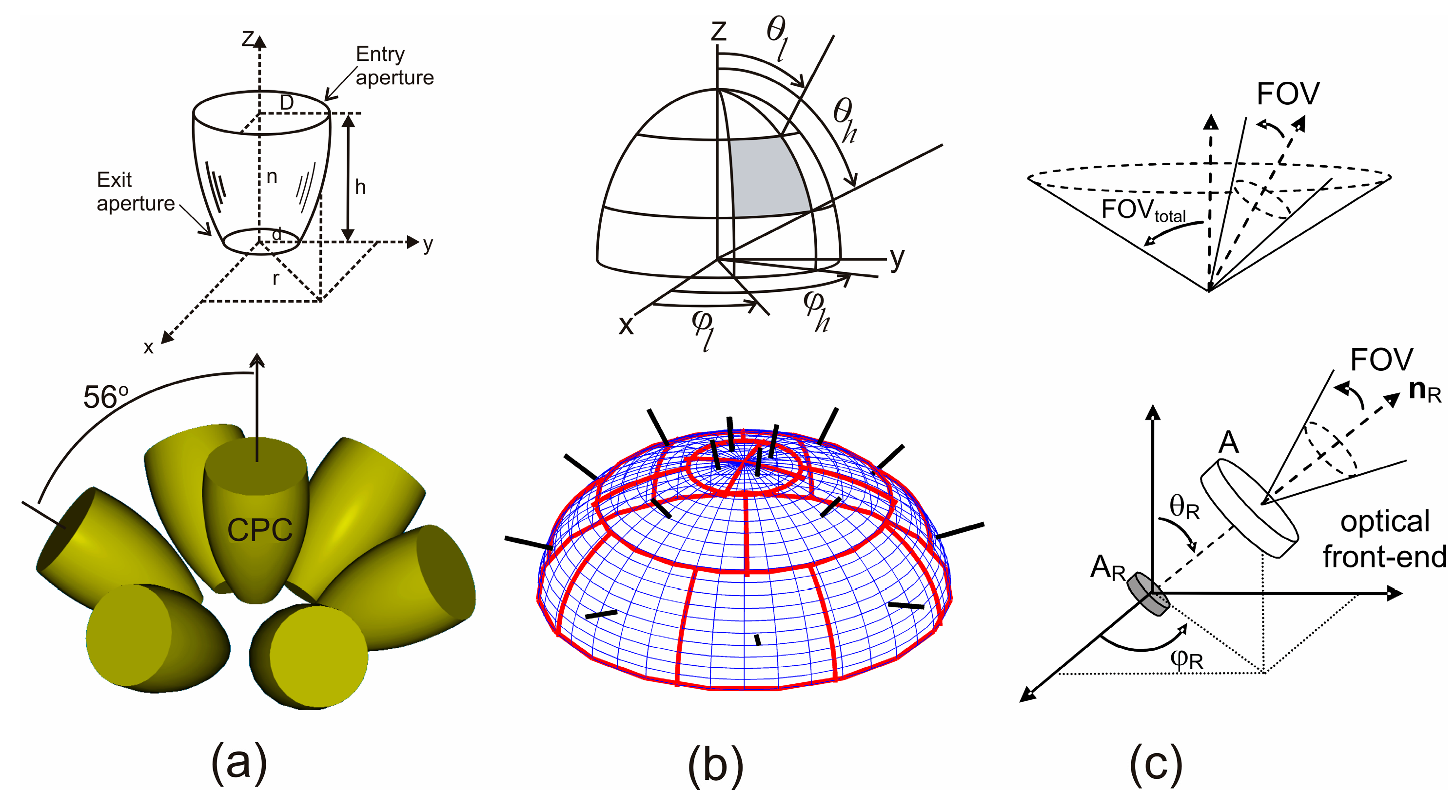
In this section, simulations are used to compare the performance of the three non-imaging angle-diversity receivers described in the previous section and shown in
Figure 3: the conventional angle-diversity receiver (CDR), the sectored angle-diversity receiver (SDR), and the self-orienting receiver (SOR). The comparison is based on calculating the rms delay spread, the path loss, and the SNR when the MRC, SB, and EGC combination techniques are employed. To this end, the simulation algorithm described in the previous section was implemented, the models for the three non-imaging angle-diversity receivers were included, and the IR signal propagation for different configurations of optical links in the room shown in
Figure 4 was studied. The simulation tool implemented allows us to study the infrared signal propagation inside any simulation environment or 3D scene. The tool features two fully differentiated parts. The first is charged with defining the 3D scene, which the user can describe by means of any CAD software that is capable of generating or storing the scene in 3DS format. In our simulations, we have used the Blender graphic design program because it offers multi-platform support in a freeware product that can output a 3DS file. The second part consists of implementing the propagation model. This refers to the mathematical models that characterize the effect of each of the elements present in the simulation environment (reflecting surfaces, emitters, and receivers), and to the simulation algorithm that, aided by these models, allows the channel response to be computed. The part of the tool that implements the propagation model and into which the 3D scene is input was programmed in C++. A detailed description of the simulation tool developed was presented in [
19], where the parallelization of the simulation algorithm was also discussed.
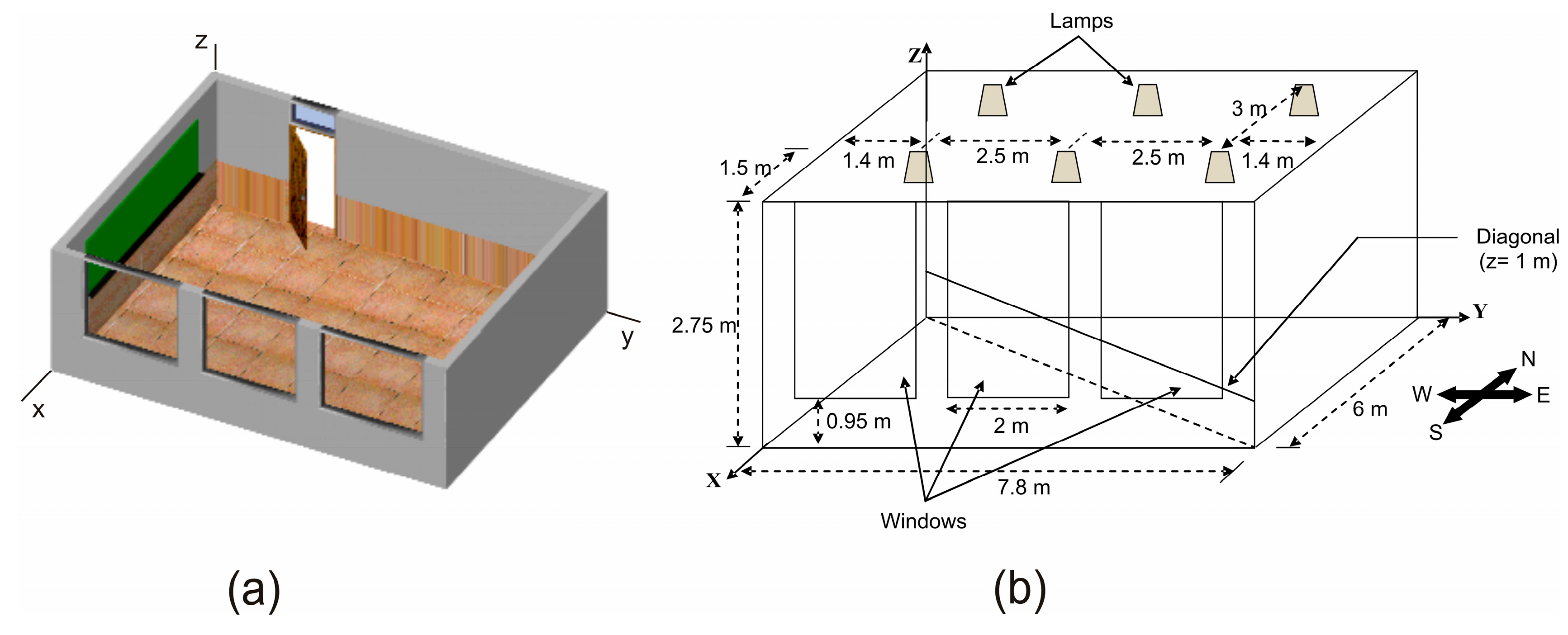
The indoor environment shown in
Figure 4 was based on the channel models for a 14 × 14 × 3 m
3 office, a 6 × 6 × 3 m
3 living room, and an 8 × 8 × 3 m
3 hospital room, which were proposed by the IEEE802.15.7 VLC work group [
28]. The room selected is almost analogous to the living room, but with a rectangular instead of square shape. Furthermore, in order to make the comparison as independent as possible of the characteristics of the emitter and the furniture distribution in the room, no obstacles and a diffuse emitter were assumed.
In general, the topology of an infrared-based sensor network can vary from a simple star network to a multihop wireless mesh network. However, regardless of the network topology, the sensor nodes should be able to collect data and route them to the sink node. That is, in a wireless sensor network there is a large number of tiny transmitters collecting data and routing them to a small number of receiver nodes. For this reason, in order to compare the performance of the three angle-diversity receivers used as the input sensor of a receiver sensor node, we have proposed a simulation scenario consisting of an angle-diversity receiver located in the centre of the room and multiple transmitters uniformly distributed along the diagonal from the northwest to the southeast of the room, as shown in
Figure 4b. As previously mentioned, the angle-diversity receiver is located in the centre of the room, 1 m above the floor and aimed vertically towards the ceiling. We have assumed that the CDR uses photodetectors with a physical area of
AR = 1 cm
2, the SOR employs a photodetector with an area of 3.53 mm
2, and the sectored receiver makes use of a hemisphere of radius
r = 1.4 cm, meaning the largest sector has a physical area of about 1 cm
2. Specifically, the sectors in the first, second and third crown of the sectored receiver have an area of 0.27 cm
2, 0.95 cm
2 and 0.92 cm
2, respectively. Every photodetector in the three angle-diversity receivers has a responsivity of 0.6 A/W. As for the emitters, they are oriented vertically towards the ceiling, 1 m above the floor, located in thirty-seven locations uniformly distributed along the northwest-southeast diagonal of the room, and modelled as a first-order Lambertian emitter with a total emitted power of 15 mW. The remaining parameters used in the simulations match those shown in
Table 1.
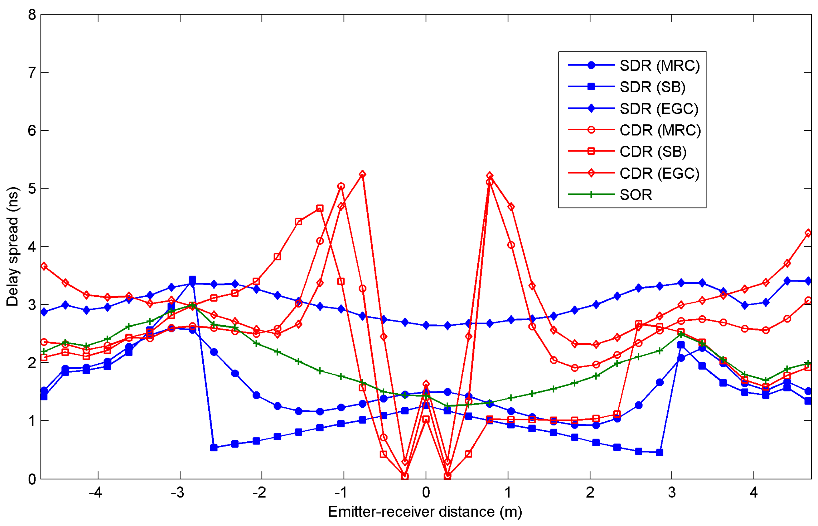
Figure 5 and
Figure 6 show the rms delay spread and the path loss, respectively, as a function of the distance between the emitter and receiver along a diagonal from the northwest (negative values or distances) to the southeast (positive values or distances) of the room shown in
Figure 4. The results were obtained for all three angle-diversity receivers, SDR, CDR, and SOR, when MRC, EGC, and SB combination techniques are applied. In the case of SOR, which only employs a photodetector element, the combining techniques are not applicable. Furthermore, as noted earlier, the SOR receiver employs a maximum search algorithm to aim the receiver in the direction of the highest SNR. In our simulations, in order to find the reception orientation with the best SNR, first the SNR is calculated for all possible reception directions, as defined by their elevation and azimuth angles in steps of its FOV. Secondly, a higher resolution search is carried out around the best SNR obtained in the previous stage, which is bounded by the receiver FOV.
Independently of the angle-diversity receiver employed in the link, all the values obtained for the rms delay spread are below 6 ns, well above the requirements for a receiver operating in a 115 kbps link, i.e., the rms delay spread parameter is not significant when selecting the angle-diversity receiver and the combination technique that provides the best performance. As for the path loss shown in
Figure 6, CDR and SOR exhibit smaller values than SDR due to the optical gain provided by the optical front-end employed for the photodetectors in both receivers. The CDR structure exhibits the smallest path loss because its photodetectors have a physical area larger than the SOR photodetector. In term of path loss, the CDR receiver offers the best power efficiency for the power transmitted by the emitter. Specifically, SOR has a path loss about 10 dBo greater than CDR when EGC is used for the emitter located in the centre of the room. The conventional angle-diversity receiver exhibits a unique behaviour when the emitter is located about 0.26 m from the centre of the room. The path loss is minimal because all the radiation is detected by the vertical element of the receiver after undergoing a single reflection. This effect also results in a minimum delay spread since all the radiation reaches the receiver at approximately the same time (see
Figure 5), and in a maximum SNR because a low path loss involves a high received power (see
Figure 7). In general, the sectored and conventional angle-diversity receivers exhibit the best path loss when EGC is employed, because all the power received by each photodetector element is collected or, put another way, EGC increases the receiver’s total FOV. In MRC, the power received by the elements with a low SNR is attenuated, and in SB, only the power received by the element with the best SNR is taken into account. In short, EGC offers the best path loss if the noise is significant and the signal power is uniformly distributed throughout the room (broadcast communication).
In order to obtain the SNR given by Equation (21), it is necessary to determine the total noise variance as the sum of the contributions from the background light-induced shot noise and thermal noise due to the amplifier. To this end, a bit rate of
Rb = 115 kbps was considered since the study involves the application of non-imaging angle-diversity receivers to indoor IR wireless sensor networks. The shot noise can be computed using Equation (23), where the incident optical power from ambient light
Pbg originates at the windows and six tungsten bulbs located in the ceiling of the room (see
Figure 4). To compute the incident optical power from the windows, each window surface is divided into small square elements of equal area (25 cm
2), and each element is modelled as a first-order Lambertian emitter with a spectral radiant emittance of 0.20 W/nm/m
2 [
8], i.e., the noise PSD of each element is 0.5 mW/nm. The noise optical power emitted by each element can be obtained by multiplying the noise PSD by
Δλ, which represents the spectral bandwidth of the optical filter used to limit the ambient radiation reaching the photodetector, which was set at 50 nm for the CDR and SOR structures and 320 nm for SDR. Therefore, applying the Monte Carlo ray-tracing algorithm to each element
E, and using Equation (8), the incident optical power from the windows act as an ambient light (noise) source that can be expressed as a sum of the form:
where
M =
tmax/
Δt is the number of time intervals of width
Δt, and
Ne is the number of elements used to divide the window surface. Moreover, the radiant intensity from the bulbs can be modelled as Lambertian sources of second order with an optical spectral density of 0.037 W/nm. Analogously to the calculation of the noise power from ambient light, the incident optical power from the bulb can be obtained by multiplying the power spectral density by
Δλ. As in the previous case, the optical power contribution from a bulb
E can be calculated by:
Assuming typical parameters for a receiver that relies on a FET-based transimpedance preamplifier, i.e., k = 1.38 × 10⁻²³ J/K, T = 295 K, η = 175 pF/cm2, Rf = 10 kΩ, gm = 40 mS, Cg = 1 pF, RD = 146 Ω, Γ = 1.5, K = 294 fA, a = 1, ID = 20 mA, I2 = 0.562, I3 = 0.0868, and If = 0.184, Equation (25), which defines the thermal noise, can be expressed just in terms of the physical area of the photodetector. Thus, the thermal noise can be easily computed for each photodetector element of the angle-diversity receiver used in the link.
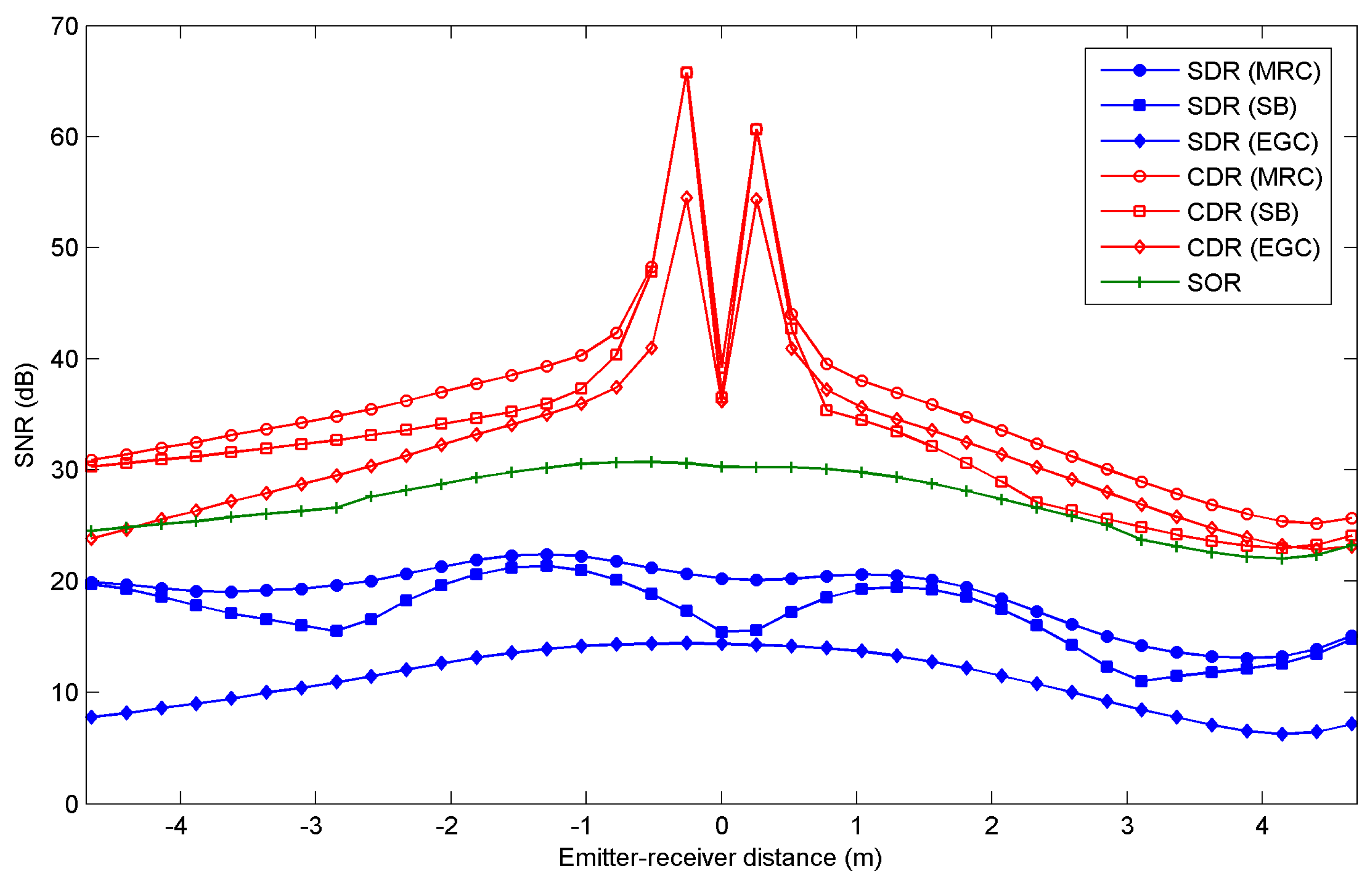
Figure 7 shows the SNR as function of the emitter-receiver distance along the northwest-southeast diagonal for the three angle-diversity receivers, when MRC, EGC, and SB are applied. In general, CDR and SDR exhibit the highest and the lowest SNR, respectively, with a difference of about 20 dB for the emitter located in the centre of the room. Independently of the receiver, the SNR degrades when the emitter is moved towards the corners of the room, similar to the path loss. Furthermore, when emitters are located along the southeast diagonal of the room, the SNRs are a little lower than along the northwest diagonal. In the southeast corner, the emitters are close to the windows, so the desired signal and the contribution from the shot noise due to the natural ambient light are received of the same direction. In short, the conventional angle-diversity receiver exhibits the best simultaneous SNR and path loss. Furthermore, as expected, for conventional and sectored angle-diversity receivers, the MRC scheme provides the best results, followed by SB and EGC. However, the MRC and SB combining techniques require estimating the SNR at each diversity branch, and the difference between the SNR obtained by MRC and EGC is only about 5 dB for the CDR structure. This is not significant when selecting the receiver and the combining technique that offer the best performance in a link operating at 115 kbps.
Assuming the emitter transmits at 115 kbps using on-off keying (OOK) with non-return-to-zero (NRZ) pulses, the channel is distortionless, the preamplifier is followed by an equalizer that converts the received pulse to one, having a raised-cosine Fourier transform with 100% excess bandwidth, and the equalizer gain is chosen so that when sampled, its output is either 0 or 2
RPS (A), ignoring noise. Each sample of the equalizer output contains Gaussian noise having a total variance that is the sum of contributions from shot and thermal noises. In these conditions [
4], the Bit Error Rate (BER) is given by:
According to Equation (35), to achieve a BER = 10
−9 requires a SNR = 15.6 dB. Based on the results shown in
Figure 7, the CDR and SOR receivers ensure a BER below 10
−9 for any location along the diagonal of the room. The minimum SNR for SDR is about 10 dB, ensuring a bit error rate below 10
−3 for a total emitted power of 15 mW. In general, regardless of the combining technique employed, CDR shows a better SNR and path loss than the SDR structure. It is also evident that in terms of both parameters, the CDR receiver provides the best performance. Although the self-orienting receiver exhibits a SNR almost similar to CDR, SOR presents a path loss worse than CDR, regardless of the combining technique applied. Furthermore, SOR needs to implement a SNR estimator, include a search algorithm that automatically aims the receiver towards the highest SNR, and incorporate an electromechanical orienting system. As was previously mentioned, the sensor nodes in a sensor network are limited in power and computational capacity. Therefore, using the SOR as the input sensor for the nodes in an indoor infrared-based sensor network requires additional power consumption and computational capacity over using a CDR in conjunction with EGC. In short, the use of a conventional angle-diversity receiver in conjunction with the EGC technique yields the best trade-off between SNR, computational capacity, and transmitted power. Finally, the use of multi-beam transmitters in conjunction with angle-diversity receivers and power efficient modulation schemes should be analyzed in future research in order to minimize the transmitted power requirements due to the communication between the sensor nodes in an infrared-based sensor network.


 ,
, 


