A Solar Panel-Integrated Modified Planner Inverted F Antenna for Low Earth Orbit Remote Sensing Nanosatellite Communication System


Abstract
:1. Introduction
2. Materials and Methods
3. Results
4. Conclusions
Author Contributions
Funding
Acknowledgments
Conflicts of Interest
References
- Temiz, F.; Durduran, S.S. Monitoring Coastline Change Using Remote Sensing and Gis Technology: A Case Study of Acıgöl Lake, Turkey; IOP Conference Series: Earth and Environmental Science; IOP Publishing: Bristol, UK, 2016; p. 042033. [Google Scholar]
- Peral, E.; Im, E.; Wye, L.; Lee, S.; Tanelli, S.; Rahmat-Samii, Y.; Horst, S.; Hoffman, J.; Yun, S.-H.; Imken, T. Radar technologies for earth remote sensing from cubesat platforms. Proc. IEEE 2018, 106, 404–418. [Google Scholar] [CrossRef]
- Heidt, H.; Puig-Suari, J.; Moore, A.; Nakasuka, S.; Twiggs, R. Cubesat: A new generation of picosatellite for education and industry low-cost space experimentation. In Proceedings of the 14th Annual/USU Conference on Small Satellites, Logan, UT, USA, 24 August 2001. [Google Scholar]
- Bouwmeester, J.; Guo, J. Survey of worldwide pico-and nanosatellite missions, distributions and subsystem technology. Acta Astronautica 2010, 67, 854–862. [Google Scholar] [CrossRef]
- Hodges, R.E.; Chahat, N.; Hoppe, D.J.; Vacchione, J.D. A deployable high-gain antenna bound for mars: Developing a new folded-panel reflectarray for the first cubesat mission to mars. IEEE Antennas Propag. Mag. 2017, 59, 39–49. [Google Scholar] [CrossRef]
- Council, N.R. Handbook of Frequency Allocations and Spectrum Protection for Scientific Uses; National Academies Press: Washington, DC, USA, 2007. [Google Scholar]
- Gao, S.; Clark, K.; Unwin, M.; Zackrisson, J.; Shiroma, W.; Akagi, J.; Maynard, K.; Garner, P.; Boccia, L.; Amendola, G. Antennas for modern small satellites. IEEE Antennas Propag. Mag. 2009, 51, 440–456. [Google Scholar] [CrossRef]
- Yekan, T.; Baktur, R. Conformal integrated solar panel antennas: Two effective integration methods of antennas with solar cells. IEEE Antennas Propag. Mag. 2017, 59, 69–78. [Google Scholar] [CrossRef]
- Rahmat-Samii, Y.; Manohar, V.; Kovitz, J.M. For satellites, think small, dream big: A review of recent antenna developments for cubesats. IEEE Antennas Propag. Mag. 2017, 59, 22–30. [Google Scholar] [CrossRef]
- Ernest, A.J.; Tawk, Y.; Costantine, J.; Christodoulou, C.G. A bottom fed deployable conical log spiral antenna design for cubesat. IEEE Trans. Antennas Propag. 2015, 63, 41–47. [Google Scholar] [CrossRef]
- Fernandes, G.; Santos, M.; Silva, V.; Almeida, J.; Nogueira, P. Thermal tests for cubesat in Brazil: Lessons learned and the challenges for the future. In Proceedings of the 67th International Astronautical Congress, Guadalajara, Mexico, 27 September 2016. [Google Scholar]
- Atcitty, S. Aihec/tcu Advanced Manufacturing Network Initiative; Sandia National Lab. (SNL-NM): Albuquerque, NM, USA, 2016. [Google Scholar]
- Crisp, N.; Smith, K.; Hollingsworth, P. Launch and deployment of distributed small satellite systems. Acta Astronaut. 2015, 114, 65–78. [Google Scholar] [CrossRef]
- Liu, X.; Jackson, D.R.; Chen, J.; Liu, J.; Fink, P.W.; Lin, G.Y.; Neveu, N. Transparent and nontransparent microstrip antennas on a cubesat: Novel low-profile antennas for cubesats improve mission reliability. IEEE Antennas Propag. Mag. 2017, 59, 59–68. [Google Scholar] [CrossRef]
- Yasin, T.; Baktur, R.; Furse, C. A comparative study on two types of transparent patch antennas. In Proceedings of the 2011 XXXth URSI General Assembly and Scientific Symposium, Istanbul, Turkey, 13–20 August 2011; pp. 1–4. [Google Scholar]
- Roh, W.-L.; Woo, J.-M. Miniaturization of microstrip antenna using folded structure with attaching plates for satellite communication terminal. In Proceedings of the 2007 IEEE Antennas and Propagation Society International Symposium, Honolulu, HI, USA, 9–15 June 2007; pp. 4709–4712. [Google Scholar]
- Haruki, H. The inverted-f antenna for portable radio units. Conv. Rec. IECE Jpn. 1982. [Google Scholar]
- Tanaka, M.; Suzuki, Y.; Araki, K.; Suzuki, R. Microstrip antenna with solar cells for microsatellites. Electron. Lett. 1995, 31, 5–6. [Google Scholar] [CrossRef]
- Sarabandi, K.; Buerkle, A.M.; Mosallaei, H. Compact wideband uhf patch antenna on a reactive impedance substrate. IEEE Antennas Wirel. Propag. Lett. 2006, 5, 503–506. [Google Scholar] [CrossRef]
- Kakoyiannis, C.G.; Constantinou, P. A compact microstrip antenna with tapered peripheral slits for cubesat rf payloads at 436 MHz: Miniaturization techniques, design & numerical results. In Proceedings of the 2008 IEEE International Workshop on Satellite and Space Communications, Toulouse, France, 1–3 October 2008; pp. 255–259. [Google Scholar]
- Wang, F.; Bin, F.; Sun, Q.; Fan, J.; Ye, H. A compact uhf antenna based on complementary fractal technique. IEEE Access 2017, 5, 21118–21125. [Google Scholar] [CrossRef]
- Podilchak, S.K.; Murdoch, A.P.; Antar, Y.M. Compact, microstrip-based folded-shorted patches: Pcb antennas for use on microsatellites. IEEE Antennas Propag. Mag. 2017, 59, 88–95. [Google Scholar] [CrossRef]
- Sato, T.; Mitsuhashi, R.; Satori, S. Attitude estimation of nano-satellite “hit-sat” using received power fluctuation by radiation pattern. In Proceedings of the 2009 IEEE Antennas and Propagation Society International Symposium, Charleston, SC, USA, 1–5 June 2009; pp. 1–4. [Google Scholar]
- Pittella, E.; Pisa, S.; Nascetti, A. Design of an antenna system for cubesat satellites. In Proceedings of the 2nd IAA Conference on University Satellites Missions and CubeSat Winter Workshop, Roma, Italy, 3–9 February 2013. [Google Scholar]
- Leao, T.F.C.; Mooney-Chopin, V.; Trueman, C.W.; Gleason, S. Design and implementation of a diplexer and a dual-band vhf/uhf antenna for nanosatellites. IEEE Antennas Wirel. Propag. Lett. 2013, 12, 1098–1101. [Google Scholar] [CrossRef]
- ISIS. Innovative Solutions in Space. Available online: https://www.isispace.nl/product/dipole-antenna/ (accessed on 26 July 2018).


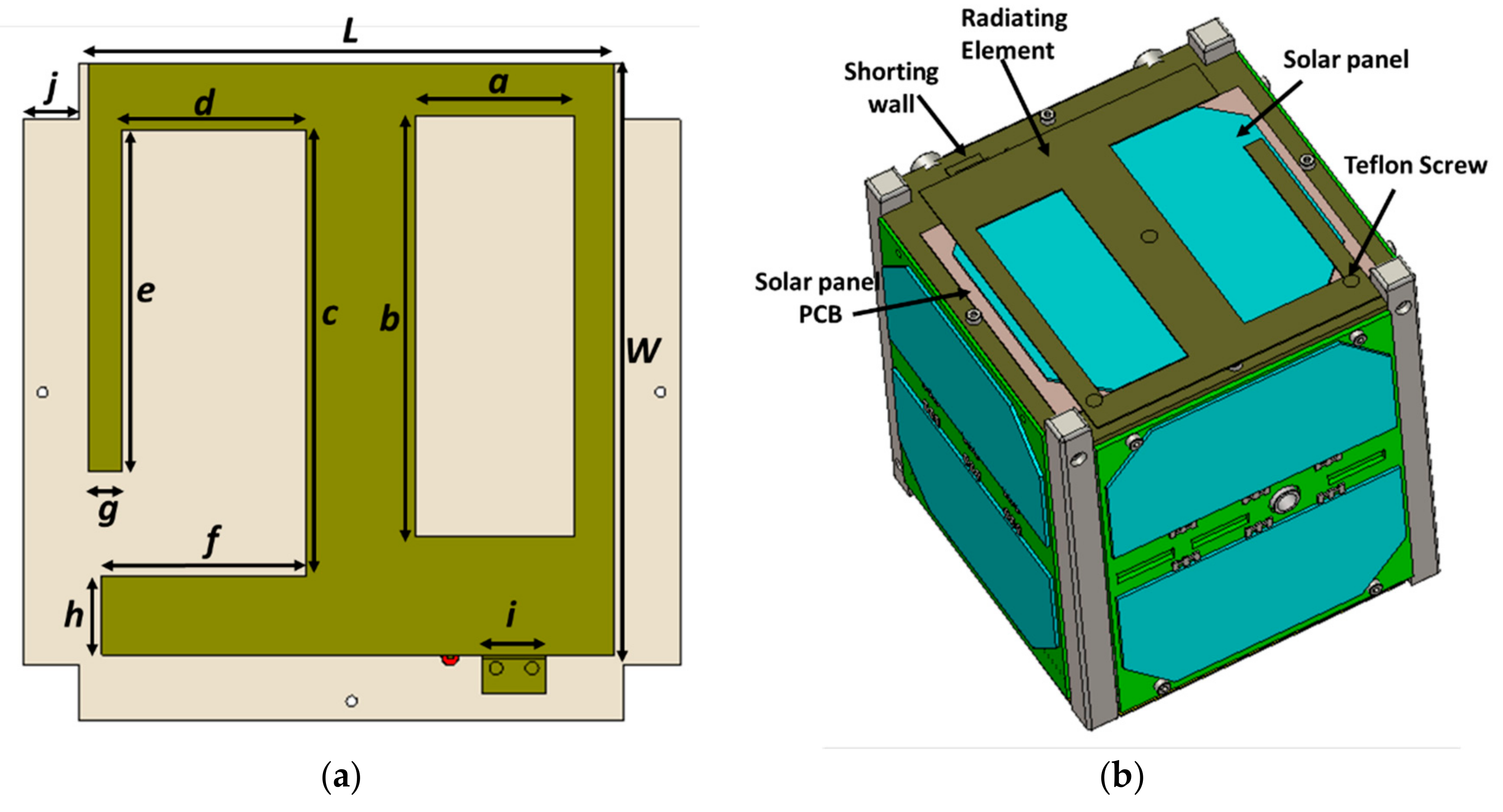
| Parameters | Value (mm) | Parameters | Value (mm) |
|---|---|---|---|
| L | 80 | e | 60 |
| W | 90 | f | 31 |
| a | 24.25 | g | 5 |
| b | 64 | h | 12 |
| c | 68 | i | 9.6 |
| d | 28 | j | 8.5 |
| Parameter | Specifications | Unit |
|---|---|---|
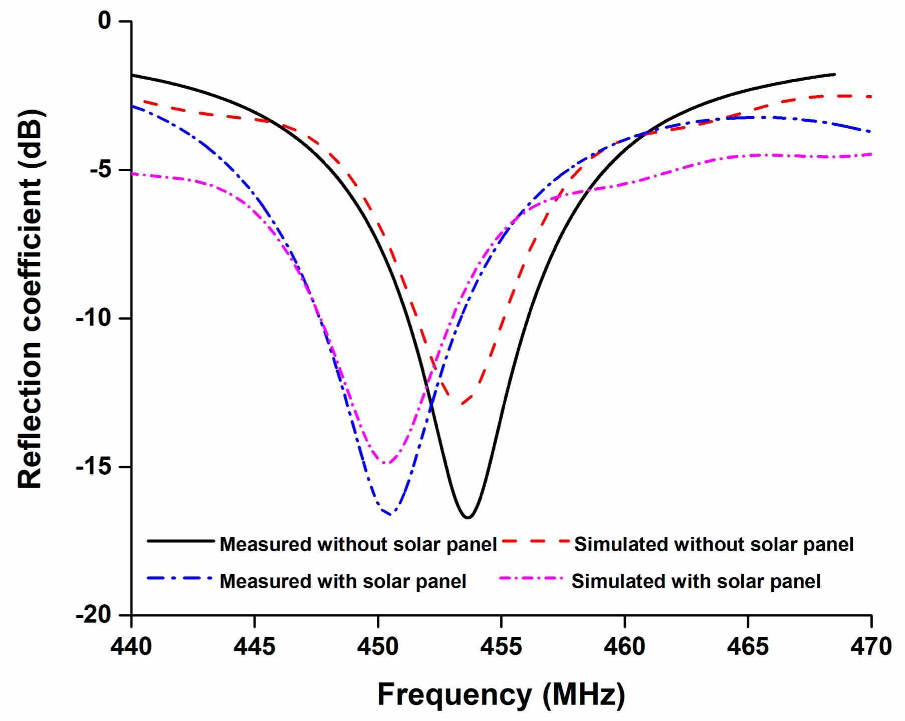
| Frequency | 447.5–453.5 | MHz |
| Impedance bandwidth (−10 dB) | 6 | MHz |
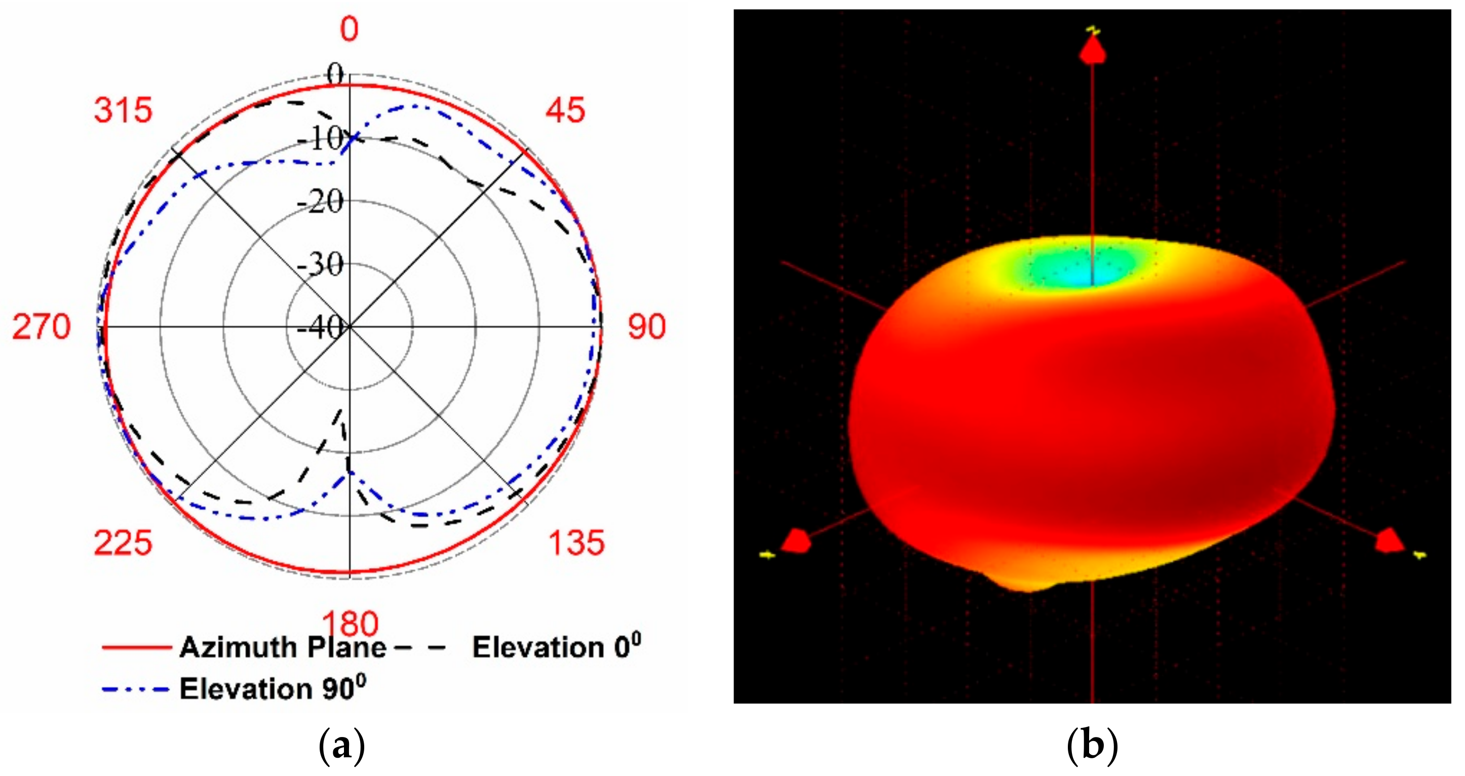
| Polarization | Linear | - |
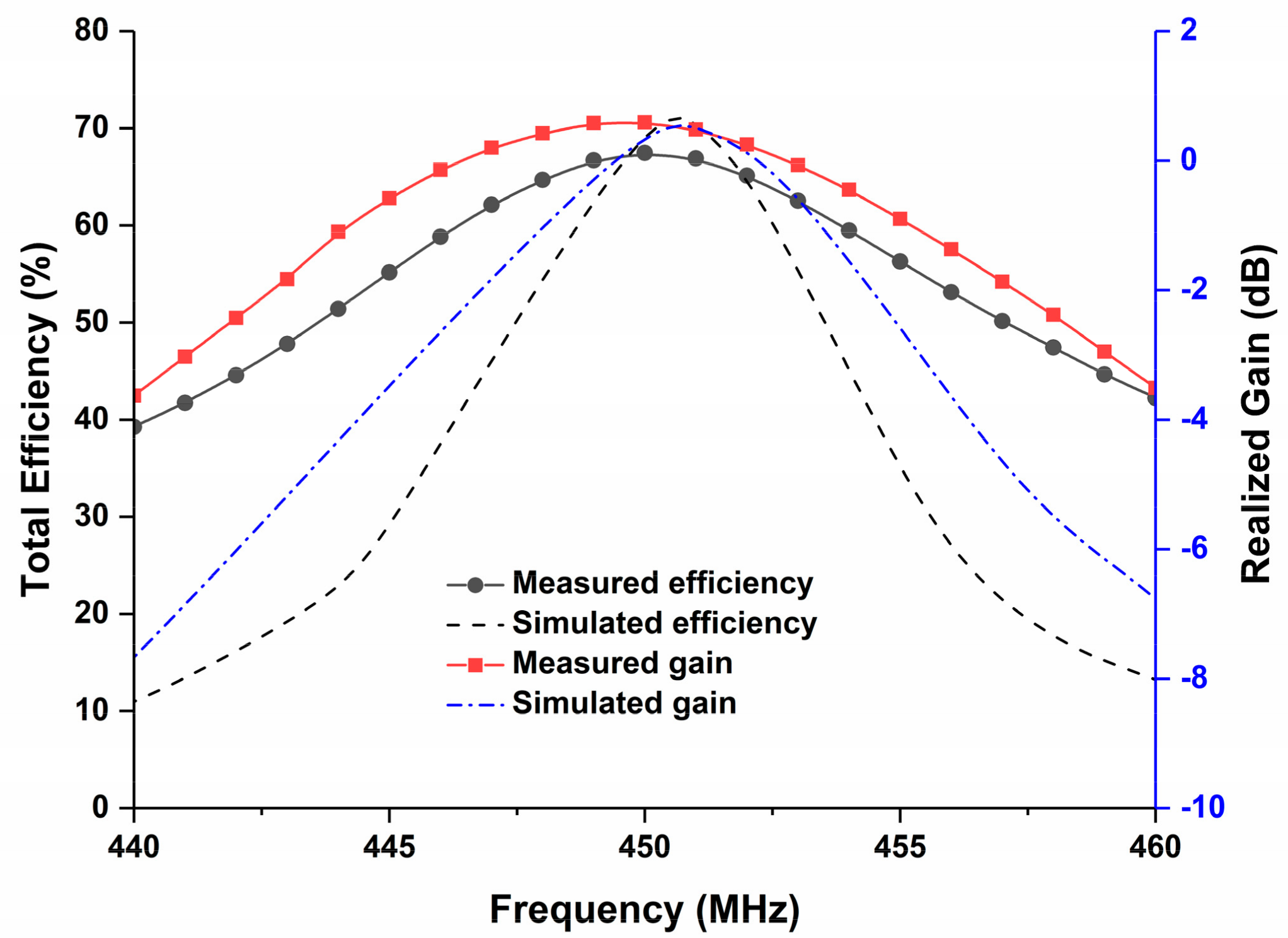
| Realized Gain | 0.6 | dB |
| Antenna Size | 80 × 90 | mm |
| Efficiency | 67.45 | % |
| Material | Brass | - |
| RF input | 50 Ω mmcx connector | - |
| Vibration Test | Qualified | - |
| Ref. No. | Antenna Type | Operating Frequency (MHz) | Antenna Size (mm) | Gain | Solar Integration Facility | Remarks |
|---|---|---|---|---|---|---|
| [19] | Printed patch | 410–485 | 220 × 220 × 28.5 | 5.2 dB | no | Too large for 1U, 2U nanosatellites. |
| [20] | Microstrip patch | 435–437 | 170 × 120 × 6.4 | 0.7 dB | no | Too large to fit with 1U nanosatellites. |
| [21] | Fractal shaped | 700–4710 | 120 × 120 × 1.6 | 1.71 dB | no | Not compact enough. Does not cover lower UHF frequency (450 MHZ) |
| [14] | Printed patch | 427.38–437.17 | 320 × 80 × 3.17 | 2.12 dB | no | Large dimension |
| [22] | Microstrip patch | 384–410 | 150 × 150 × 37 | 0.4 dB | no | Low gain with large dimension. |
| [23] | Dipole | 430 | 160 | 2.15 dB | yes | Externally mounted with satellite structure |
| [24] | Monopole | 435–438 | 175 | 2.35 dBi | yes | Deployable complexity |
| [25] | Monopole | 146 & 438 | 513.6 × 10 × 10 | 2.06 dBi at 146 MHz 3.35 dBi at 438 MHz | yes | Deployable complexity |
| Proposed Antenna | Modified PIFA | 447.5–453.5 | 80 × 90 × 0.5 | 0.6 dB | yes | Deployable complexity free |
© 2018 by the authors. Licensee MDPI, Basel, Switzerland. This article is an open access article distributed under the terms and conditions of the Creative Commons Attribution (CC BY) license (http://creativecommons.org/licenses/by/4.0/).
Share and Cite
Alam, T.; Islam, M.T.; Ullah, M.A.; Cho, M. A Solar Panel-Integrated Modified Planner Inverted F Antenna for Low Earth Orbit Remote Sensing Nanosatellite Communication System. Sensors 2018, 18, 2480. https://0-doi-org.brum.beds.ac.uk/10.3390/s18082480
Alam T, Islam MT, Ullah MA, Cho M. A Solar Panel-Integrated Modified Planner Inverted F Antenna for Low Earth Orbit Remote Sensing Nanosatellite Communication System. Sensors. 2018; 18(8):2480. https://0-doi-org.brum.beds.ac.uk/10.3390/s18082480
Chicago/Turabian StyleAlam, Touhidul, Mohammad Tariqul Islam, Md. Amanath Ullah, and Mengu Cho. 2018. "A Solar Panel-Integrated Modified Planner Inverted F Antenna for Low Earth Orbit Remote Sensing Nanosatellite Communication System" Sensors 18, no. 8: 2480. https://0-doi-org.brum.beds.ac.uk/10.3390/s18082480