1. Introduction
This engineering-geological study was motivated by the problem of potholes (local morphological depressions) in the bottom of the Wisła River in the gravel-sand alluvium behind the dam of the biggest Polish water power plant Włocławek. The formation of potholes endangers the concrete structures of the water power plants and the threshold which serves for partial water flow stabilization.
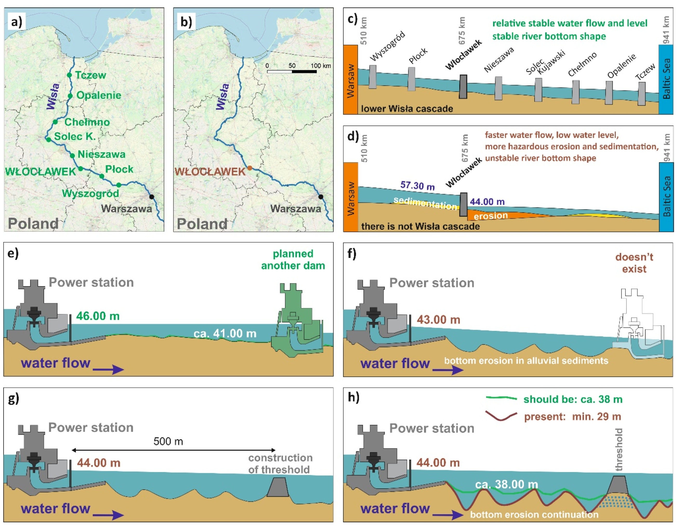
The Polish government originally planned to build eight water power plants north of Warszawa on the biggest Polish river, the Wisła River (
Figure 1a), which would optimize the hydraulic conditions of the river in relation to the ongoing erosion and sedimentation processes in the river. The construction of dams may have a varying influence on the geological environment of river courses [
1,
2,
3,
4]. Due to financial constraints, only one water power plant was built in 1970: Włocławek water power plant (
Figure 1b). The originally planned hydrological conditions arising from the set of eight dams is shown in
Figure 1c. The absence of the seven dams has caused extreme hydrological conditions, with a significant drop in the river level (
Figure 1d), leading to significant erosion processes behind the dam.
Figure 1e shows what the originally planned conditions would be, while
Figure 1f shows the unfavourable hydrological conditions as the construction of only one water power plant caused more significant erosion and formation of a high number of potholes. As a result, a protective threshold was constructed on the river, which is supposed to improve the conditions (
Figure 1g). The conditions improved partially, but it is evident that the forming potholes endanger the threshold stability (
Figure 1h) [
5,
6,
7,
8].
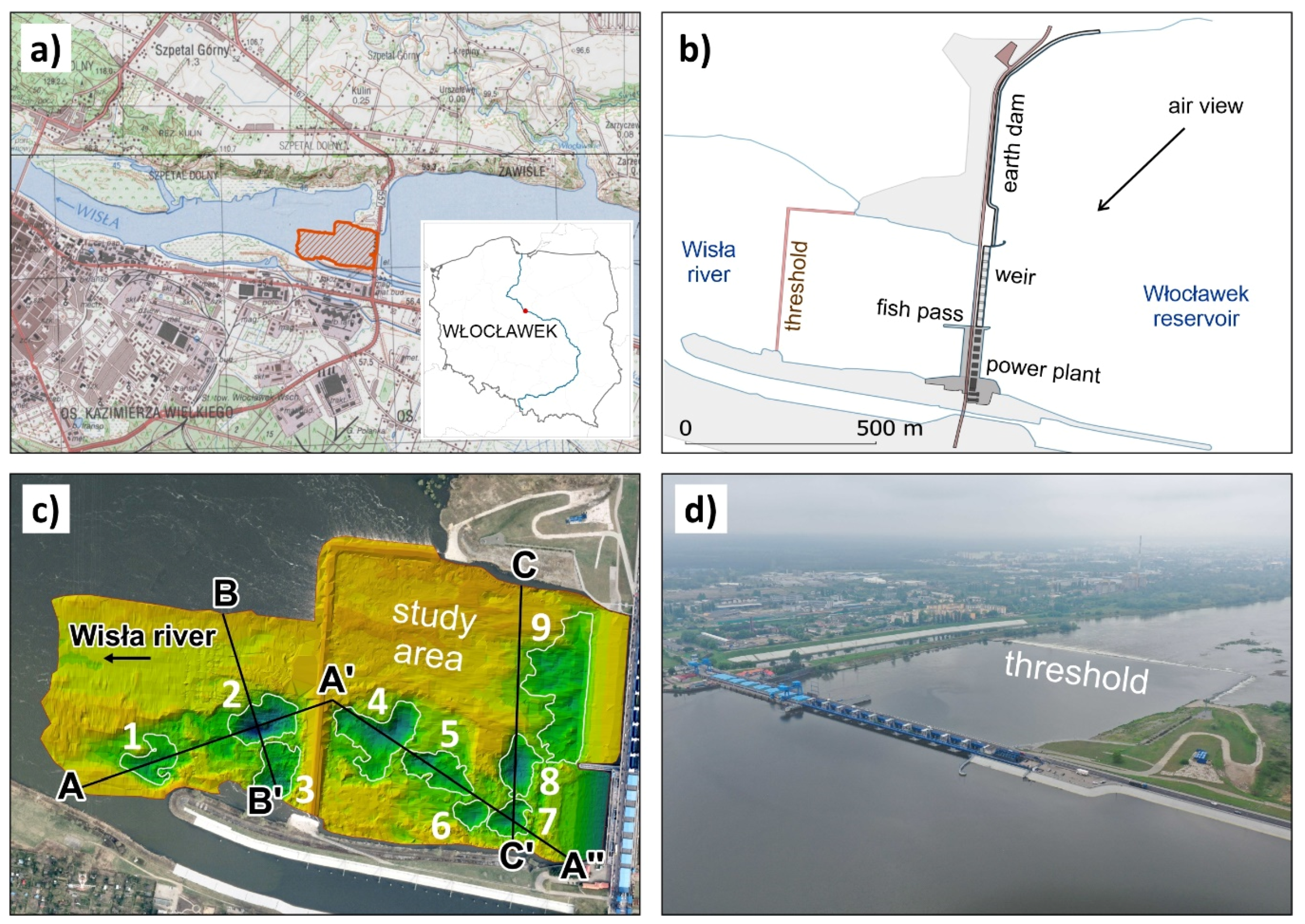
The specific conditions of the engineering-geological case study are related to the research in the study area (
Figure 2) of alluvial gravel-sand environment of the Wisła River behind the Włocławek water power plant dam. This stretch of the river suffers from intense river bed erosion, which causes extensive geomorphological changes resulting in a high number of potholes in this geological environment. The morphology of river channels is very important from the point of view of the fluvial process character and formation of potholes [
9,
10,
11]. One of the factors that influences the formation of potholes is the drop in the Wisła River water level behind the dam, which amounts to 13 m. Another factor is significant changes in the water flow and water level, due to the varying requirements for the technical-economic operation of the water power plant. Particularly, this concerns the requirements related to peaks. Another factor is changes in the water regime caused by extraordinary processes, such as floods.
As reported in Hazell et al. [
12], Delgado et al. [
13], Rommens et al. [
14]; Kiracofe et al. [
15], and Marschalko et al. [
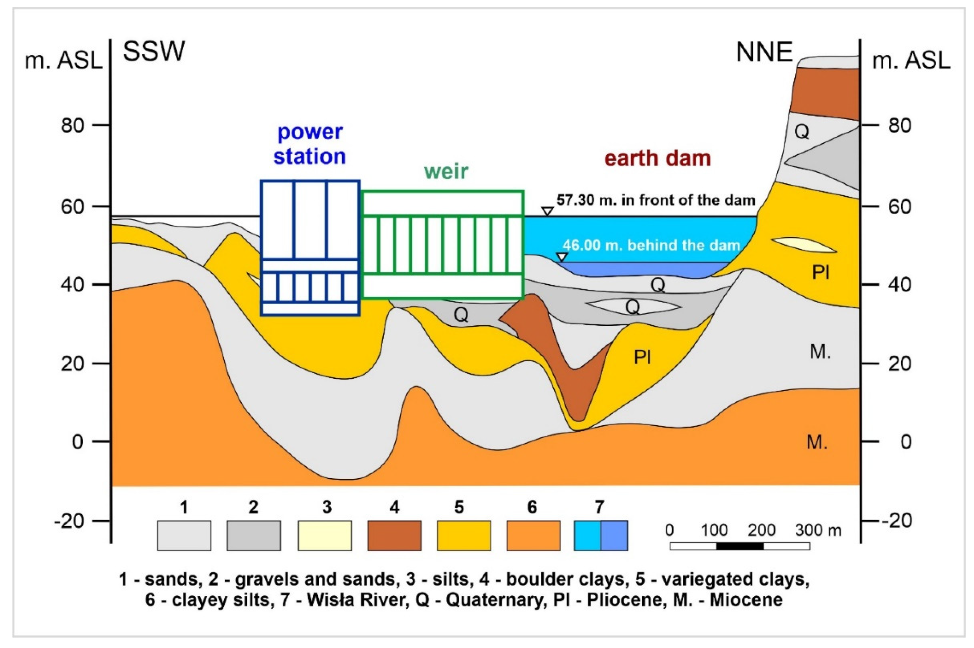
16], the character of the rock material influences the geological structure of the alluvium, as well as the physical-mechanical parameters, enabling the planning activities in the geological environment. The foundation conditions of the Włocławek water power plant can be seen in
Figure 3, while the most important section with the most prominent interaction is bound onto the Quaternary gravel and sand. The next section is characterized by Pliocene clay. In the bedrock, there are Miocene sand and clayey silts. Geological structure bedrock is one of the most important factors in the river activity. For this reason, it is decisive whether the bedrock is made of rocks or soils as it conditions the resistance of the rock massif [
17,
18,
19]. In light of the above, the Wisła River bedrock is made up of low-resistant soils.
So far, the risk of potholes formation has been assessed by means of classic geodetic measurements (theodolite) and analogue depth measurements (manual probe/lead line). These measurements were taken locally, only on a few profiles, without giving full information about the size and shape of the bottom and potholes. Classical survey methods do not provide with data for reliable monitoring. It was difficult to apply effective methods to eliminate the risk of dam structure damage.
The proposed methodology covers the whole process of testing the safety of power plant structures: planning/conducting an integrated high-accuracy bathymetric GNSS and hydroacoustic measurements, developing the data, analysing it, selecting criteria, assessing risks, and proposing appropriate solutions.
The purpose of this study was to evaluate the erosion changes of the river bed and their effect on the power plant operation. Despite the fact that a threshold was built to stabilize the water flow in the river, the study is also important because the potholes in its vicinity influence the stability of the threshold. This study also aims to propose a remediation project to backfill the potholes. This may lead to the stabilization of the river bed and the surrounding structures of the water power plant.
The final result of this work is a customized river bottom hazard map, which takes into account a high, medium, and low risk levels of the potholes for the water power plant structure. The research method was a 4-year-long geodetic/bathymetric monitoring of the river bed carried out using integrated methods of GNSS (Global Navigation Satellite System), RTS (Robotized Total Station), and SBES (Single Beam Echo Sounder). Next, with the help of the new methodology, we produced a special, customized river bottom hazard map. The production of the map allowed to create a technical remediation proposal for holes backfilling and to propose a future monitoring system for the river bed, including its frequency, for the sake of sustainable operation of the Włocławek water power plant.
2. Bathymetric Monitoring
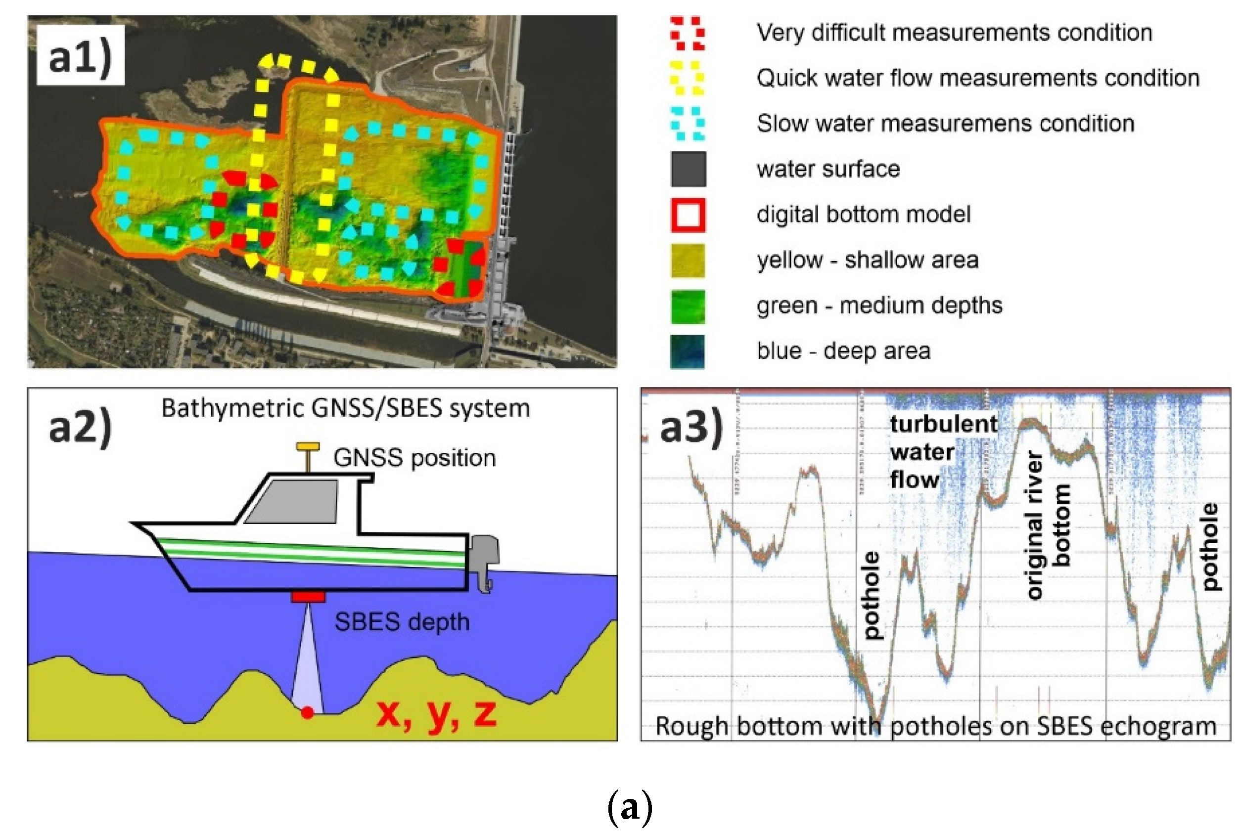
To analyse the erosion and sedimentation process of the Wisła River bottom below the Włocławek power plant (
Figure 4(a1)), 4-year long geodetic/bathymetric measurements were conducted. In general, bathymetry shows a 3D model of the underwater bottom shape. This allows analysing changes in the shape of the bottom erosion and movements of sedimentation. Currently, research on the aquatic environment is carried out using modern geodetic and hydroacoustic measurement techniques, supported by remote sensors and processing algorithms [
20,
21,
22,
23]. An integrated GNSS satellite positioning, Robotized Total Station (RTS) and a Single Beam Echosounder System (SBES) were used for hydroacoustic depth measurements (
Table 1). These bathymetric surveys were made in real time using a small motor boat (
Figure 4(a2)).
The key problem during practical surveys (
Figure 4(a3)) were the height of the water surface and waterflow speed during depth measurements (rough and choppy water and quick water level changes depending on the schedule of the power plant work and on the distance from the dam). Particularly dangerous were the areas behind the turbines of the power plant and behind the damming threshold. Zones of different measurement conditions are presented in
Figure 4(a1).
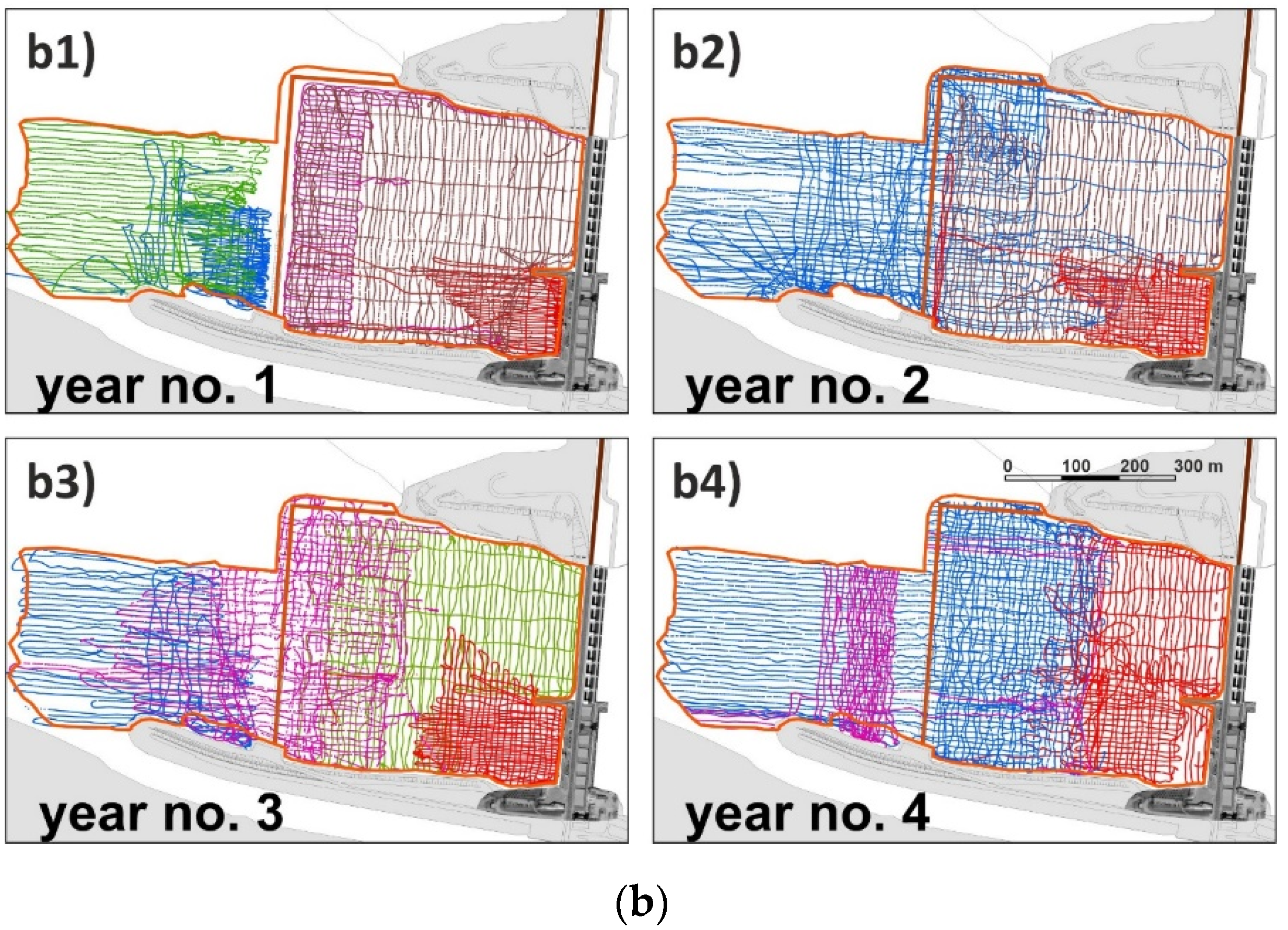
Measurements should be carried out on the basis of designed measurement profiles (the same each year). In fact, the routes differed slightly from the planned lines due to navigation errors, difficult measurement conditions and power plant operation schedule. That is why the GNSS/RTS/SBES bathymetric measurements were carried out in several stages in each of the four subsequent years of river bed inventory (
Figure 4(b1–b4)).
All depth measurements should be related to the common water level (reduced to the common vertical datum). In inland bathymetry, this physical water surface is usually stable and can only change slightly in time (do not need any reductions; easy to elaborate raw data). An exception to the rule is reservoirs of hydroelectric power stations, where the water level could change significantly over time and distance. The example is the biggest flowing power station in Poland: Włocławek hydroelectric power plant which causes up to 2 m vertical water level movement during the day.
Bathymetric data were acquired using single beam echosounder which needs vertical motion corrections (heave). Additionally, all raw depth data should be referenced to the common water level.
To reach the final reduced depth measurements, it is necessary to obtain the precise vertical position of the platform. The classical geodetic Total Station, GPS RTK (Real Time Kinematic), GNSS OTF (on the fly), and readings from local water gauges were used for sub-centimetre estimation of water level changes during hydroacoustic measurements. The finally reduced bathymetric data were used to elaborate 3D bottom elevation models for further erosion and sediment analysis.
3. Evaluation of River Bed Changes
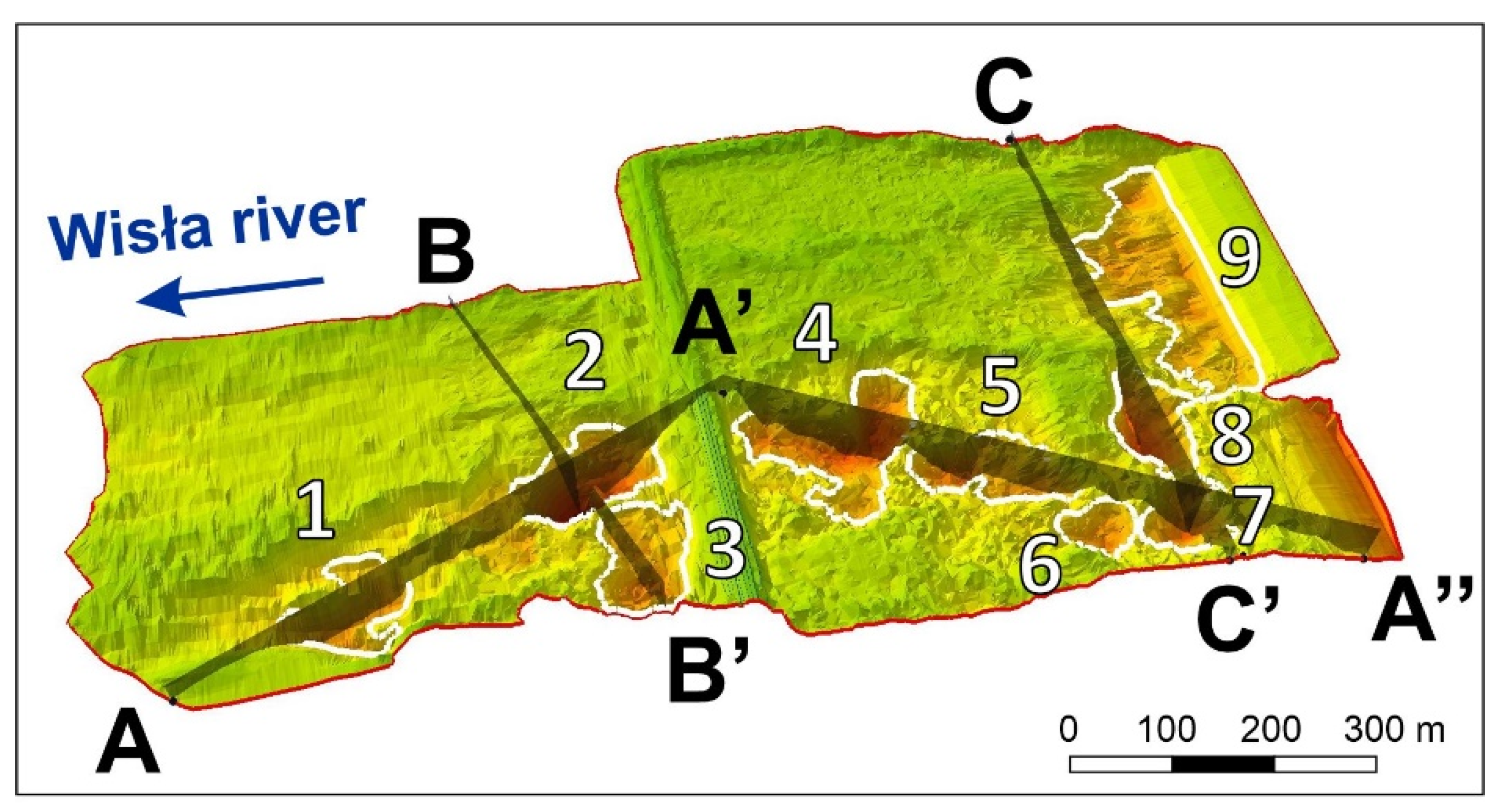
The area of interest was spatially evaluated based on basic criteria: selected model cross-sections (AA’, A’A”, BB’, CC’ - to represent the vertical morphological changes in the river bed) and the changes in the cubic capacity of the Wisła River bed erosion, generally, on the whole study area, and additionally in the biggest potholes (1–9), selected for analysis (
Figure 5).
3.1. Cross-Section Evaluation
The first to be evaluated were selected model cross-sections (
Figure 5) to represent the vertical morphological changes in the river bed due to erosion or sedimentation during the 4-year monitoring (
Figure 6).
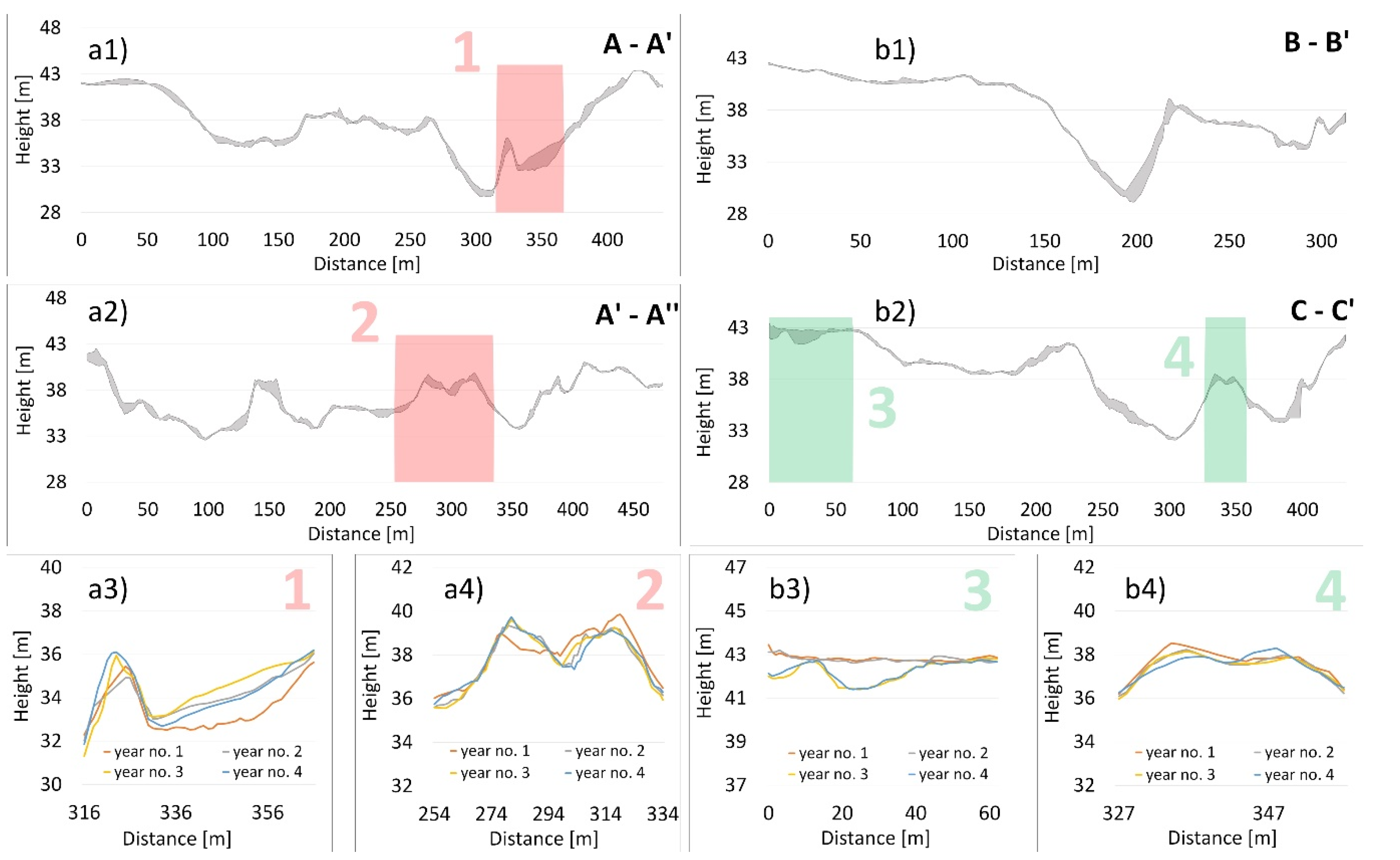
When evaluating the vertical cross-sections, it showed that the changes in the river bed were very heterogeneous. Therefore, we chose the most optimal representation of the river bed changes in the form of envelope curves of the river bed morphology between the first and last year of the monitoring. In each cross-section, we selected one point which details the curves of each monitored year.
If we evaluate the cross-section A-A′ and A′-A′′ (
Figure 6(a1)), we may say that the changes occurred up to 2.14 m, and the average change was 0.52 m. It is clear that conditions altered; erosion prevailed in some places, while sedimentation prevailed elsewhere. This was also related to the hydrological conditions in time in the Wisła River, including floods. It is clear from the cross-section A-A′ (
Figure 6(a3)) that the most prominent erosion occurred in the first year of monitoring, while later on sedimentation dominated. On the contrary, the cross-section A′-A′′ (
Figure 6(a4)) shows the lowest positions in some places in the fourth year of monitoring.
When evaluating the cross-section B-B′ (
Figure 6(b1)), the most remarkable changes occurred in the pothole of 180 to 220 m, where the biggest erosion change (2.47 m) was reported in the slope of the hole. In the cross-section C-C’, the biggest changes were observed in the section from 0 to 40 m, and 260 to 280 m on the left slope of the hole. At the elevation at 250 m and at the end of the cross-section behind 400 m (
Figure 6(b2)), further significant changes were noted. When evaluating
Figure 6(b3), it is clear that there has been a prominent erosion change in the river bed during the monitoring, which correlated with the periods of floods (26 days of enormous water discharge before the third stage of bathymetric measurements (Figure 9a at the top)). The part of the object shown in
Figure 6(b4) is significant, since it gives detail information on changes in the morphological elevation, where erosion dominates on the left side and sedimentation on the right.
Erosion processes in the river alluvial geological environment have been studied by [
3,
24,
25,
26,
27]. It is evident that the formation of potholes is one of the basic hazards for water power plant structures.
3.2. Riverbed Capacity/Area Evaluation or Bottom Erosion/Sedimentation Evaluation
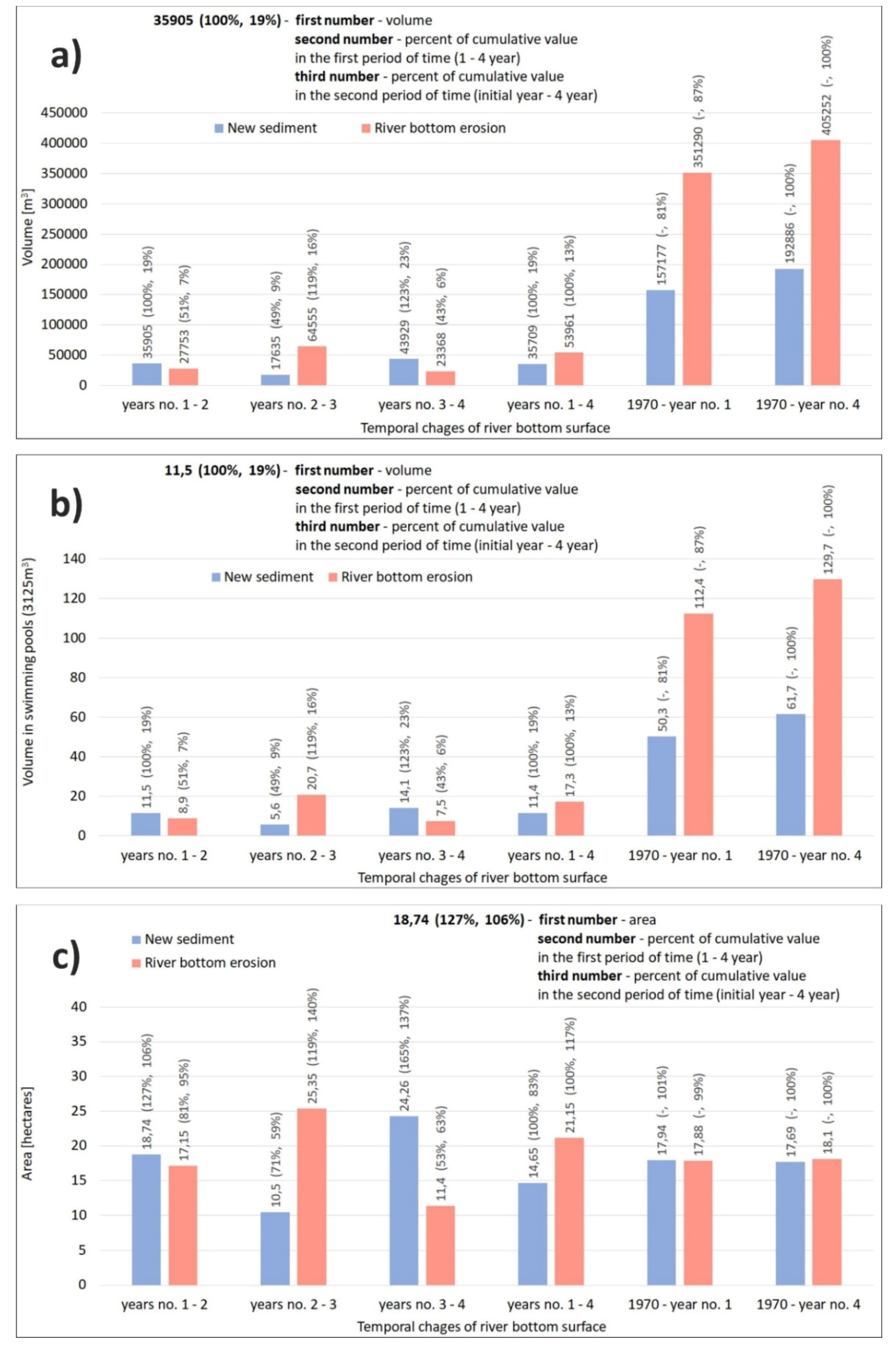
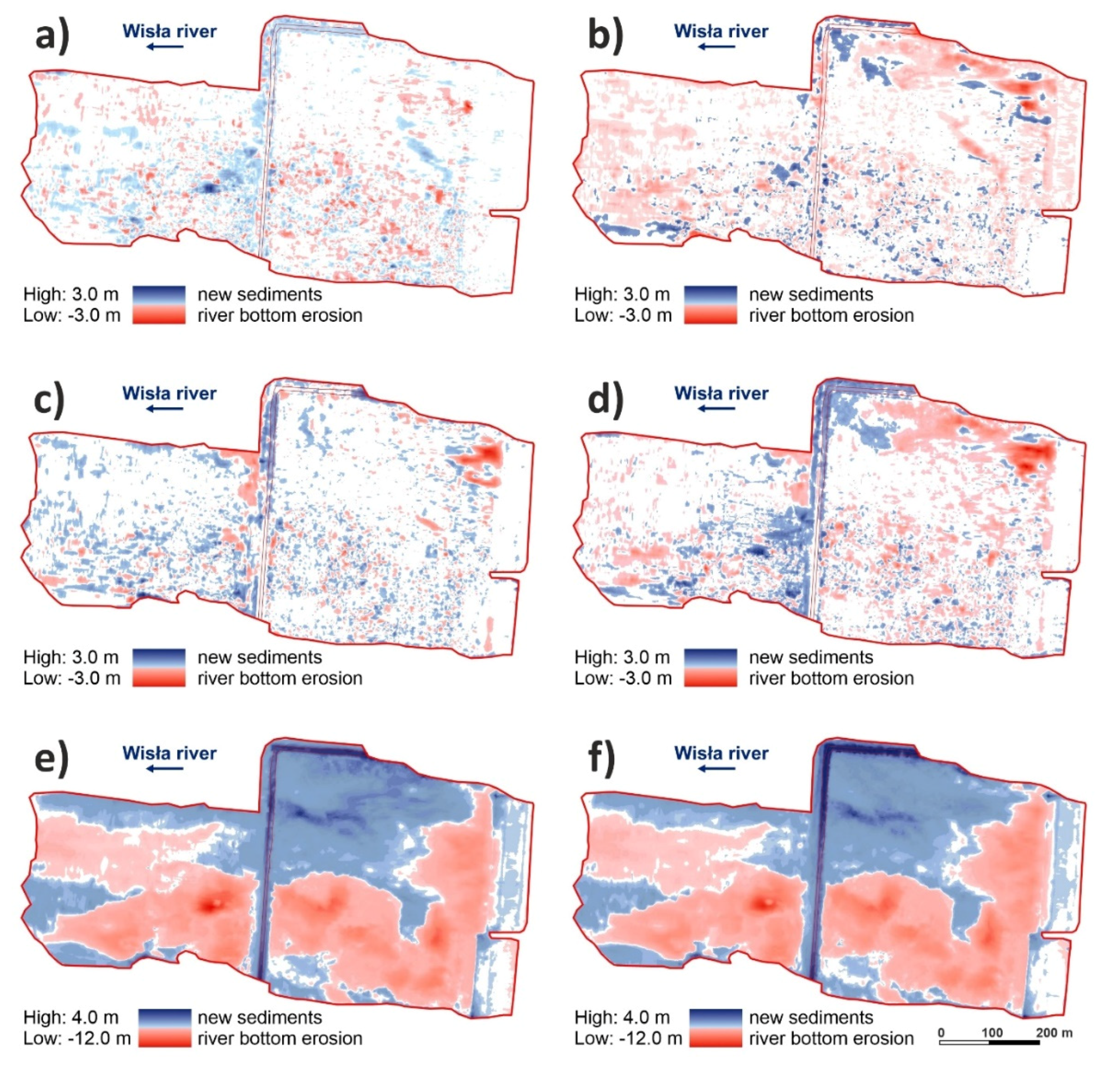
When evaluating the changes in the cubic capacity and surface of the Wisła River bed erosion (
Figure 7 and
Figure 8) during the 4-year monitoring, the most prominent changes occurred between the second and third year, when erosion washed away 64,555 m
3 of gravel-sand (
Figure 7a and
Figure 8b). This corresponds to 20.7 Olympic-size pools of 3125 m
3 (
Figure 7b). This amount represents 119% of the final second and third year change. At the same time, it has amounted to 16% of the overall change since the construction to the last year of monitoring. The spatial distribution of the change is shown in
Figure 8b. This most prominent change is manifested in the largest area of red colour in
Figure 8b (change between year 2 and year 3 of monitoring) when compared to
Figure 8a (change between year 1 and year 2 of monitoring),
Figure 8c (change between year 3 and year 4 of monitoring), and
Figure 8d (change between year 1 and year 4 of monitoring).
During the 4-year monitoring, the final river bed erosion amounted to 53,961 m
3 (
Figure 7a), which is a capacity of 17.3 Olympic-size pools (
Figure 7b). However, the 4-year value represents only 13% of the total erosion (
Figure 7a) of the river bed since the construction to the end of the monitoring. In other words, the change amounts to 87% of gravel-sand (capacity of 351,290 m
3, or 112.4 Olympic-size pools (
Figure 7b)) since the construction (
Figure 7b) to the start of the 4-year monitoring. Therefore, changes were enormous, but distributed in time (
Figure 7 and
Figure 8).
The most prominent spatial change in erosion (area) was observed between year 2 and year 3, i.e., 25.35 ha (
Figure 7c and
Figure 8b). During the 4-year monitoring, the area affected by erosion was 21.15 ha (
Figure 7c and
Figure 8d). Interestingly, the overall spatial change in erosion since the dam construction to the end of monitoring corresponds to a smaller area (18.1 ha) than the area identified during the 4-year monitoring (
Figure 7c). This is explained by the fact that the area of interest is too small for the final change to manifest in this parameter during such a long period.
Apart from the erosion process, the geological environment of river alluvia is influenced by sedimentation processes, which was reported in [
28,
29,
30,
31,
32,
33].
When assessing the changes in the cubic capacity of new sediments in the area of interest, we found that the most prominent change during the 4-year monitoring was observed between year 3 and year 4, i.e., 43,929 m
3 (
Figure 7a). This corresponds to 23% of all new sediments since the dam construction. At the end of the 4-year monitoring, the amount was 35,709 m
3 (
Figure 7a, 11.4 Olympic-size pools (
Figure 7b)), which is 19% of all new sediments since the dam was constructed. The difference was caused by erosion because the newly settled soils were reduced by intense erosion in year 3 and year 4. The overall change since the dam construction to the end of monitoring was 192,886 m
3 (
Figure 7a), which corresponds to 61.7 Olympic-size pools (
Figure 7b).
As for the evaluation of new sediments in the area of interest, we found that the biggest quantity of sediments was identified in the area between year 3 and year 4, i.e., 24.26 ha, which corresponds to 137% of the total change since the dam construction (
Figure 7c). This may be explained by the biggest flood on the Wisła River being in year 3 (
Figure 9a at the top). At the end of the 4-year monitoring, the area affected by new sediments was 14.65 ha, which corresponds to 83% of the total change only. The overall area affected by new sediments is 17.69 ha (
Figure 7c).
If we evaluate the changes caused by river bed erosion, as well as the deposition of new sediments related to the geometry of the study area (
Figure 8), more significant changes were clearly observed between the year of construction (1970) and the final year of monitoring (
Figure 8f) than during the 4-year monitoring (
Figure 8d). At the same time, it is possible to observe the dominant direction of pothole formation on the gravel-sand bottom of the Wisła River in the area of interest, i.e., Włocławek dam. This dominant direction is east–west. The direction is an arc, which mirrors the shape of the Wisła River, while it is bound onto the left bank in the direction of water flow. The abundance of potholes is influenced by the location of discharge from the dam on the left bank, and the direction of the dominant flow (east–west) (
Figure 5 and
Figure 8e,f).
3.3. Potholes Evaluation
In the area of interest, there are nine partial potholes (morphological depressions,
Figure 2 and
Figure 5). The majority of them are in the south of the area of interest, which is caused by the direction of dominant discharge from the dam. On the contrary, the sedimentation is higher in the north.
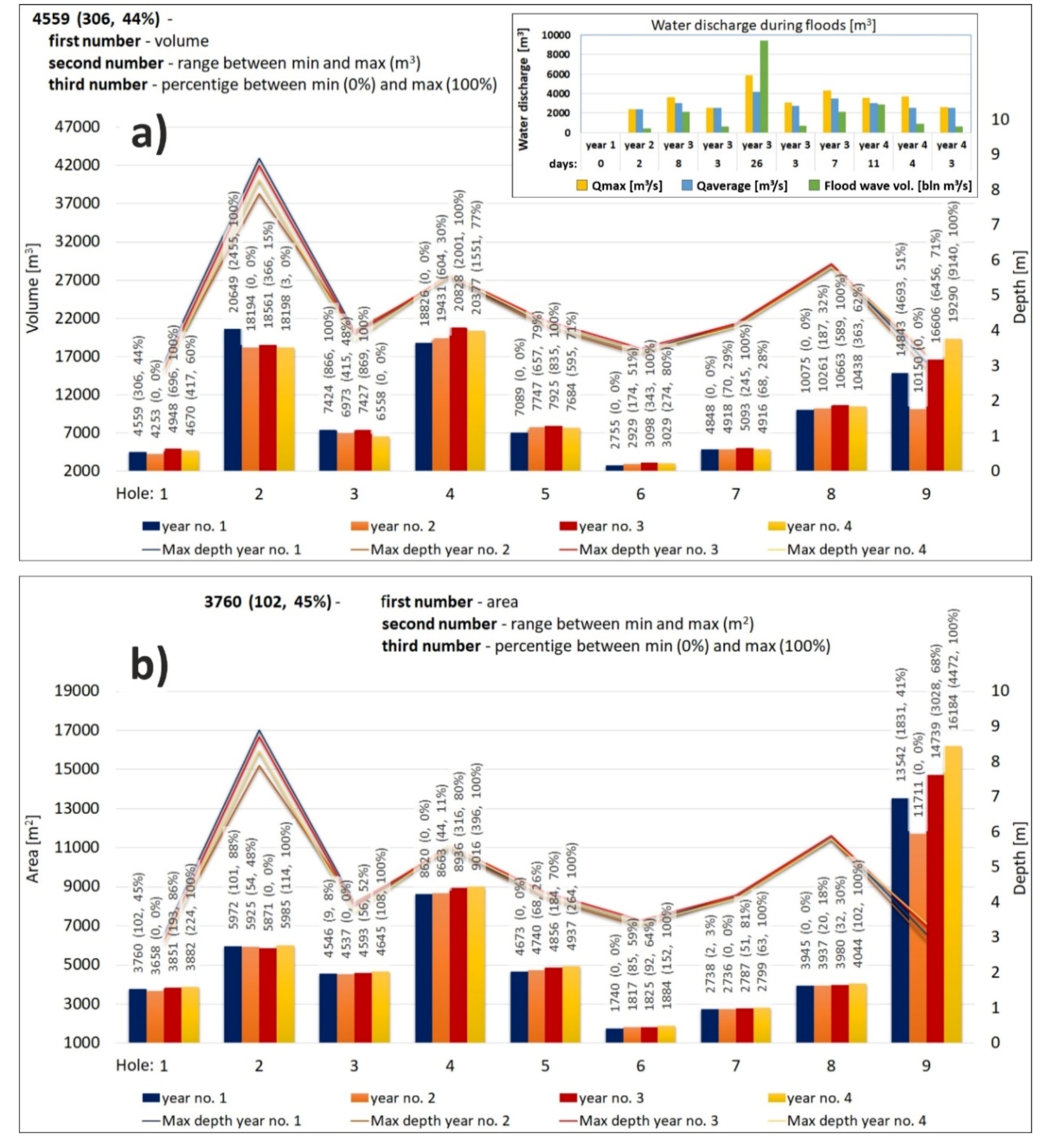
The graph with pothole quantification is presented in
Figure 9. When evaluating the 4-year monitoring of the river bed as for the cubic capacity of the nine measured potholes, the most prominent erosion occurred in pothole 2 and pothole 4 (
Figure 9a). The hazard related to the potholes lies in the fact that they are situated in the vicinity of the threshold. In year 3, we identified the capacity of 20,828 m
3 in pothole 4.
The nine potholes observed in connection with the changes in the cubic capacity were classified into three groups of analogous behaviour (
Figure 9). In potholes 1 to 3, which are located behind the threshold, the trend was a gradual increase and decrease in the values during the 4-year monitoring. On the contrary, in potholes 4 to 8, which are situated in front of the threshold in the direction of the dominant flow, there was a rising trend in the first three years of monitoring, followed by a slight decrease in year 4. This is related to the floods in year 3 and year 4 (see
Figure 9a at the top). A specific feature is pothole 9, which is located outside the discharge from the dam. Changes manifest here only during floods, i.e., there was a gradual trend of increasing sediments between years 2 and 4.
The examination of the correlations of maximum depths in the different years of monitoring and comparing these to the cubic capacity of the potholes (
Figure 9a), renders clear correlations. The only outlier is pothole 9, which is much shallower than the other potholes, which is explained by its location outside the discharge area from the power plant. This means that it gets affected only during floods, when the increased discharge influences this section too.
When evaluating the spatial distribution of the different potholes, it is clear that the largest is pothole 9, i.e., 16,184 m2 although its genesis is related to floods and position outside the discharge from the dam. The second largest pothole is pothole 4, with an area of 9016 m2 in year 4. Interestingly, this area is less deep than pothole 2, even though pothole 4 is larger. The third largest pothole is pothole 2 (5985 m2 in year 4 of monitoring), which is the deepest pothole in the area of interest.
4. Customized River Bottom Hazard Map for Remediation Purposes
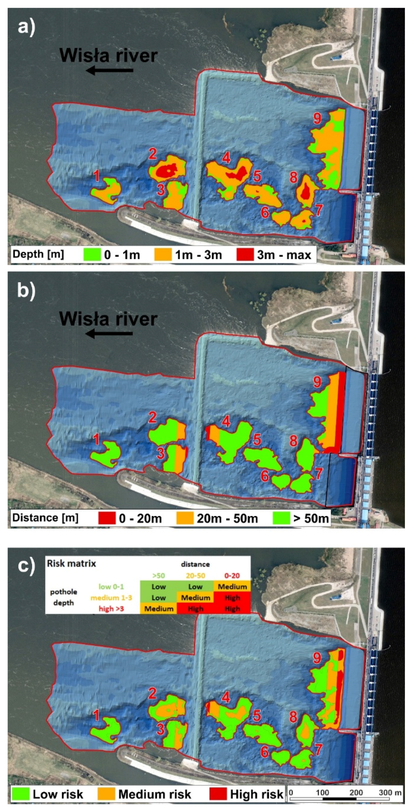
We produced a customized river bottom hazard map for remediation purposes based on the combination of two risk criteria (
Figure 10).
The first criterion is the pothole depth (
Figure 10a), where the category of low risk is related to potholes 0–1 m based on empirical evidence. The category of medium risk is characterized by pothole depth of 1–3 m. The category of high risk includes potholes over 3 m deep.
The second criterion is the distance from the dam structures (
Figure 10b), where, based on empirical evidence, the low-risk category has potholes of more than 50 m from the nearest power plant structure. The distance of potholes from the nearest power plant structures in the medium-risk category is 20–50 m. The potholes in the high-risk category are 0–20 m from the nearest power plant structures.
The final customized river bottom hazard map for remediation purposes was produced via the combination of factors of potholes’ depth and their distance from dam structure. The final categories of low risk, medium risk, and high risk were plotted based on the matrix in
Figure 10c.
Figure 10 shows the geometric distribution of both risk factors in the area of interest that influence the final hazard map.
First, we show the first criterion of pothole depth hazard (
Figure 10a) distributed in the zones. There we can see that the deepest category of high-risk concerns only some potholes, i.e., potholes 2, 4, 5, 7 and 8.
The second hazard criterion expresses the distance of potholes from the nearest power plant structure, which shows in the map in two ways (
Figure 10b). The first is the distance of potholes from the dam, where only a part of pothole 9 is in the most critical zone (0–20 from the dam). In the medium-risk zone, there are parts of potholes 7 and 8. The second distance is the distance of potholes from the threshold, where parts of potholes 3 and 4 are located in the high-risk category, while parts of potholes 2, 3 and 4 are in the medium-risk category.
In the final hazard map (
Figure 10c), parts of potholes 4, 9, and a small part of pothole 2 are in the high-risk category. Pothole 9 is located close to the dam, while potholes 4 and 2 are near the threshold. The medium-risk category concerns potholes 2, 3, 4, 5, 7, 8, and 9. Remediation backfilling is recommended only in potholes that combine the high-risk and medium-risk category of pothole depth and are located within 50 m of the power plant structures, i.e., potholes 9, 7, 4, 3, and 2.
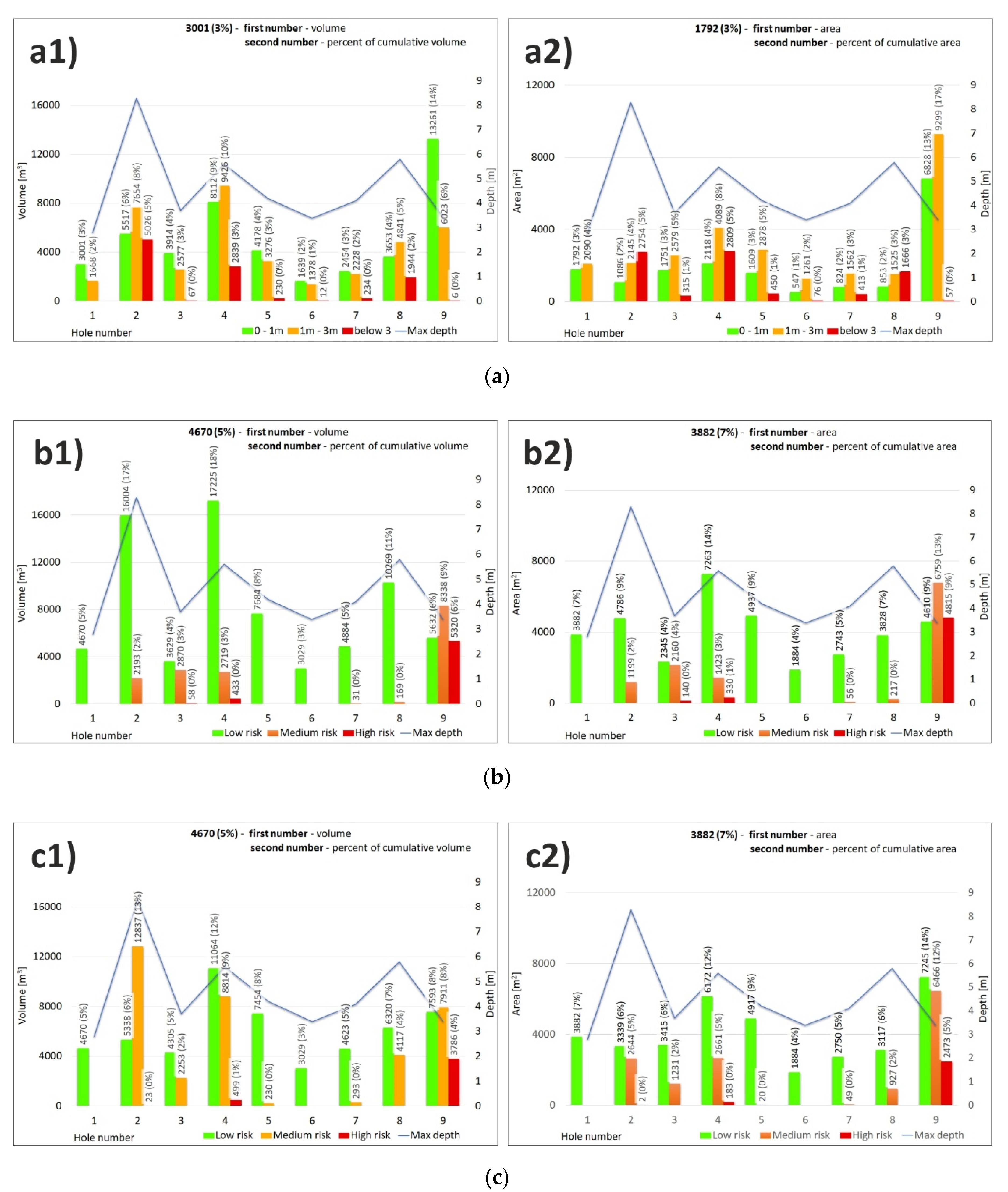
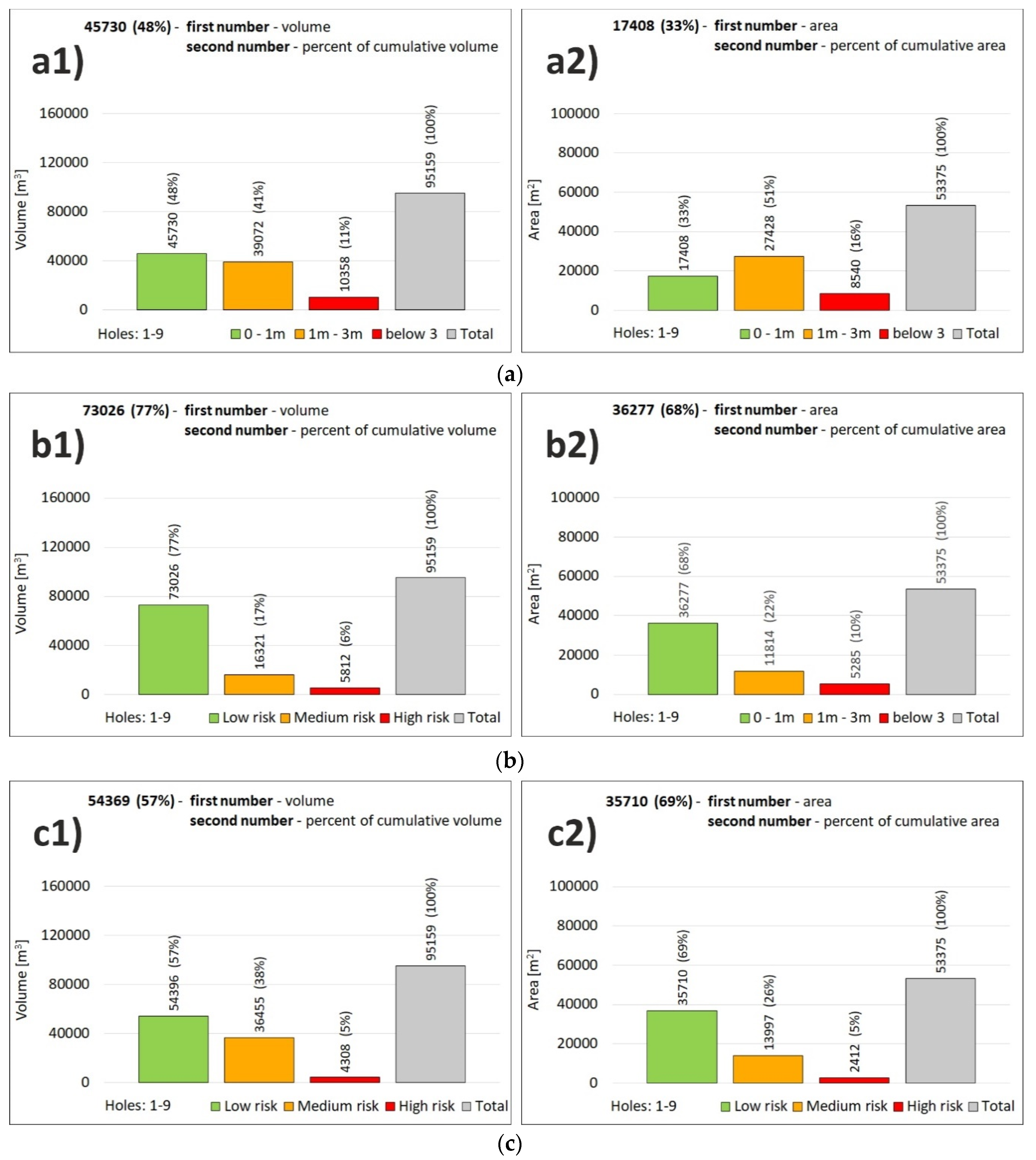
The quantification of the 4-year-monitoring results were plotted as the risk categories in the river bottom hazard map is manifest in
Figure 11, while
Figure 11(a1,b1,c1) represent the results as cubic capacity (m
3), and
Figure 11(a2,b2,c2) shows the area (m
2) changes in the categories.
As for the quantification of the first factor (
Figure 11(a1,a2)) using the pothole depth, we may say that as many as 7 parts of different potholes were in the high-risk category, while the highest cubic capacity and area are related to parts of pothole 2 (5026 m
3), 4 (2839 m
3), and 8 (1944 m
3). When quantifying the second factor of the pothole distance from the dam/threshold (
Figure 11(b1,b2)), the high-risk category includes pothole 9 (5320 m
3), which is located close to the dam. The least concerning are potholes 4 (433 m
3) and 3 (58 m
3). The combined evaluation in the final map of hazard caused a redistribution of the risk categories, while the high-risk category concerns only potholes 9 (3786 m
3) and 4 (499 m
3) (
Figure 11(c1)).
When looking at the distribution of area from the point of view of the categories, the most abundant is the low-risk category. This is explained by the shape of the potholes, where the largest parts of the potholes are shallow. The second most abundant category is the medium-risk category. The third is thus the high-risk category with the deepest potholes near the power plant structures.
Overall, the capacity of all the potholes amounts to 95,519 m
3 (
Figure 12(c1)) and area of 53,375 m
2 (
Figure 12(c2)). These two characteristics are important for the economic aspects of the remediation process as they express the maximum mass needed to be backfilled. The map in
Figure 10 is relevant for the technical implementation, logistics, access roads to the potholes, and distribution of the backfill materials in the area.
The high-risk category is the least abundant with the capacity of 4308 m
3, which is 5% of all interest area pothole cubic capacity (
Figure 12(c1)). As for the area, the value is 2412 m
2 (
Figure 12(c2)). The medium-risk category is the second most abundant with the capacity of 36,455 m
3 (38% of the total pothole cubic capacity). The area of the category covers 13,997 m
2, i.e., 26% of all pothole area. The low-risk category is related to pothole capacity of 54,396 m
3 (57% of the total pothole cubic capacity). As for the area, the category concerns 35,710 m
2 (69% of all potholes).
5. Conclusions
Based on the evaluation of the 4-year engineering-geological geodetic/bathymetric monitoring of Wisła River bottom in the area of Włocławek water power plant, we may conclude that there is a dynamic erosion activity, which leads to the formation of potholes. It is evident that the distribution of the activity is heterogeneous in time and space, while there is a dominant east–west direction in the formation caused by the location of the discharge from the dam near the left bank. The southern part of the river bed is clearly influenced by the formation of potholes due to erosion. On the other hand, the north side is rather characterized by increased sedimentation.
The quantification of these changes shows that the most prominent changes occurred between 1970 (year of dam construction) and the beginning of the 4-year monitoring, i.e., capacity of 351,290 m3 (87%). The 4-year monitoring covered only 13% of the total loss in the alluvial sediments due to erosion, and only a 19% increase in the new sediments. This implies that it is not important to carry out an annual monitoring of the whole area, but focus on the zones near the dam and threshold only.
Using a new methodology, we produced a special customized river bottom hazard map for remediation purposes, which considered two risk factors, i.e., the pothole depth and the pothole distance from the power plant structures. As for the risk categories, the high-risk category contains 5% of potholes (4308 m3), the medium-risk category contains 38% of potholes (36,455 m3), and the low-risk category has 57% of potholes (54,396 m3). The overall pothole capacity is 95,159 m3. The newly proposed methodology for pothole assessment is useful for any dam in analogous geological conditions, i.e., with alluvial gravel-sand sediments in the surroundings of dam structures.
The research resulted in a remediation project plan in the form of pothole backfilling. We proposed to backfill only those potholes that combine the high-risk and medium-risk category with the distance below 50 m from the power plant structures. The 4-year monitoring helped us to understand the spatial and depth heterogeneity of pothole occurrence to be marked in a map, based on which backfilling may be implemented. The 4-year long monitoring showed there is no need for annual monitoring. It is sufficient to carry out monitoring biannually, and the monitoring may be selective only with the high-risk zone within 20 m from the power plant concrete structures.
The methodology of the research study may be applied to other water structures with analogous conditions and problems. In case of such problems, it is important to deal with the pothole remediation, as well as to design optimal distances between water structures, in order to ensure an optimal water flow stabilization.
Author Contributions
Data curation, D.P. and T.T.; Formal analysis, M.M. and I.Y.; Funding acquisition, D.P.; Investigation, D.P., T.T. and B.M.; Methodology, D.P., M.M., T.T. and D.N.; Software, T.T.; Validation, D.P., M.M., I.Y. and B.M.; Visualization, D.P., T.T. and D.N.; Writing—original draft, D.P., M.M. and T.T.; Writing—review & editing, D.P., M.M., T.T., D.N., I.Y. and B.M. All authors have read and agreed to the published version of the manuscript.
Funding
This research was founded by: University of Warmia and Mazury, grant number N N526 227339, and VŠB—Technical University of Ostrava, grant number SP2019/131.
Acknowledgments
Authors thank VŠB—Technical University of Ostrava for the support of the project (SP2019/131), within which this article was prepared. The authors thank the University of Warmia and Mazury in Olsztyn for financial support in the implementation of geodetic and bathymetric measurements, on the basis of which this article was prepared.
Conflicts of Interest
The authors declare no conflict of interest
References
- Magirl, C.S.; Hilldale, R.C.; Curran, C.A.; Duda, J.J.; Straub, T.D.; Domanski, M.; Foreman, J.R. Large-scale dam removal on the Elwha River, Washington, USA: Fluvial sediment load. Geomorphology 2015, 246, 669–686. [Google Scholar] [CrossRef] [Green Version]
- Randle, T.J.; Bountry, J.A.; Ritchie, A.; Wille, K. Large-scale dam removal on the Elwha River, Washington, USA: Erosion of reservoir sediment. Geomorphology 2015, 246, 709–728. [Google Scholar] [CrossRef]
- Siqueira, A.G.; Azevedo, A.A.; Dozzi, L. Monitoring program of reservoir bank erosion at porto primavera dam, parana river, sp/ms, brazil. In Engineering Geology for Society and Territory-Volume 3: River Basins, Reservoir Sedimentation and Water Resources; Springer International Publishing: Berlin/Heidelberg, Germany, 2015; pp. 351–355. ISBN 9783319090542. [Google Scholar]
- Kong, D.; Miao, C.; Wu, J.; Borthwick, A.G.; Duan, Q.; Zhang, X. Environmental impact assessments of the Xiaolangdi Reservoir on the most hyperconcentrated laden river, Yellow River, China. Environ. Sci. Pollut. Res. 2016, 24, 4337–4351. [Google Scholar] [CrossRef] [PubMed]
- Babiński, Z.; Habel, M. Hydromorphological conditions of the lower Vistula in the development of navigation and hydropower. Acta Energetica 2013, 2, 83–90. [Google Scholar] [CrossRef] [Green Version]
- Majewski, W. Design, Studies, Construction and Operation Problems During 40 Years of the Exploitation of Hydraulic Project Wloclawek. In Experimental and Computational Solutions of Hydraulic Problems, Proceedings of the 32nd International School of Hydraulics Experimental and Computational Solutions of Hydraulic Problems, GeoPlanet-Earth and Planetary Sciences, Łochów, Poland, 4 January 2013; Springer: Berlin/Heidelberg, Germany, 2013; pp. 181–193. [Google Scholar] [CrossRef]
- Majewski, W. The Hydraulic Project Włocławek: Design, Studies, Construction and Operation. Acta Energetica 2015, 1, 33–40. [Google Scholar] [CrossRef]
- Szulwic, J.; Przyborski, M.; Szczechowski, B.; Szubiak, W.; Widerski, T. Photogrammetric Development of the Threshold Water at the Dam on the Vistula River in Wloclawek from Unmanned Aerial Vehicles (UAV). In Water Resources, Forest, Marine and Ocean Ecosystems, Proceedings of the 15th International Multidisciplinary Scientific Geoconference (SGEM), Albena, Bulgaria, 18–24 June 2015; SGEM: Albena, Bulgaria, 2015; Volume 1, pp. 493–500. [Google Scholar] [CrossRef]
- Kondolf, G.M.; Curry, R.R. Channel erosion along the Carmel river, Monterey county, California. Earth Surf. Process. Landf. 1986, 11, 307–319. [Google Scholar] [CrossRef]
- Church, M. Bed material transport and the morphology of alluvial river channels. Annu. Rev. Earth Planet. Sci. 2006, 34, 325–354. [Google Scholar] [CrossRef]
- Malatesta, L.C.; Prancevic, J.P.; Avouac, J. Autogenic entrenchment patterns and terraces due to coupling with lateral erosion in incising alluvial channels. J. Geophys. Res. Earth Surf. 2017, 122, 335–355. [Google Scholar] [CrossRef]
- Hazell, J.R.T.; Cratchley, C.R.; Preston, A.M. The location of aquifers in crystalline rocks and alluvium in Northern Nigeria using combined electromagnetic and resistivity techniques. Q. J. Eng. Geol. Hydrogeol. 1988, 21, 159–175. [Google Scholar] [CrossRef]
- Delgado, J.; Alfaro, P.; Andreu, J.; Cuenca, A.; Domenech, C.; Estévez, A.; Soria, J.; Tomàs, R.; Yébenes, A. Engineering-geological model of the Segura River flood plain (SE Spain): A case study for engineering planning. Eng. Geol. 2003, 68, 171–187. [Google Scholar] [CrossRef]
- Rommens, T.; Verstraeten, G.; Bogman, P.; Peeters, I.; Poesen, J.; Govers, G.; Van Rompaey, A.; Lang, A. Holocene alluvial sediment storage in a small river catchment in the loess area of central Belgium. Geomorphology 2006, 77, 187–201. [Google Scholar] [CrossRef]
- Kiracofe, Z.A.; Henika, W.S.; Schreiber, M.E. Assessing the Geological Sources of Manganese in the Roanoke River Watershed, Virginia. Environ. Eng. Geosci. 2017, 23, 43–64. [Google Scholar] [CrossRef]
- Marschalko, M.; Putiška, R.; Yilmaz, I.; Niemiec, D.; Cheng, X.; Dostal, I.; Koleňák, P. A case study for identification of organic–silt bottom sediments in an artificial lake formed in gravel alluvium in the geotourism locality of Slnečné Jazerá in Senec (Bratislava, Slovakia). Q. J. Eng. Geol. Hydrogeol. 2019, 53, 276–282. [Google Scholar] [CrossRef]
- Tooth, S.; Brandt, D.; Hancox, P.; McCarthy, T. Geological controls on alluvial river behaviour: A comparative study of three rivers on the South African Highveld. J. Afr. Earth Sci. 2004, 38, 79–97. [Google Scholar] [CrossRef]
- Konsoer, K.; Rhoads, B.L.; Langendoen, E.J.; Best, J.; Ursic, M.E.; Abad, J.D.; García, M.H. Spatial variability in bank resistance to erosion on a large meandering, mixed bedrock-alluvial river. Geomorphology 2016, 252, 80–97. [Google Scholar] [CrossRef]
- Sinha, R.; Mohanta, H.; Jain, V.; Tandon, S.K. Geomorphic diversity as a river management tool and its application to the Ganga River, India. River Res. Appl. 2017, 33, 1156–1176. [Google Scholar] [CrossRef]
- Popielarczyk, D.; Templin, T.; Łopata, M. Using the geodetic and hydroacoustic measurements to investigate the bathymetric and morphometric parameters of Lake Hancza (Poland). Open Geosci. 2015, 7, 854–869. [Google Scholar] [CrossRef]
- Templin, T.; Popielarczyk, D.; Kosecki, R. Application of Low-Cost Fixed-Wing UAV for Inland Lakes Shoreline Investigation. Pure Appl. Geophys. 2017, 175, 3263–3283. [Google Scholar] [CrossRef] [Green Version]
- Popielarczyk, D. RTK Water Level Determination in Precise Inland Bathymetric Measurements. In Proceedings of the 25th International Technical Meeting of The Satellite Division of the Institute of Navigation (ION GNSS 2012), Nashville, TN, USA, 17–21 September 2012; pp. 1158–1163. [Google Scholar]
- Łopata, M.; Popielarczyk, D.; Templin, T.; Dunalska, J.; Wisniewski, G.; Bigaj, I.; Szymański, D. Spatial variability of nutrients (N, P) in a deep, temperate lake with a low trophic level supported by global navigation satellite systems, geographic information system and geostatistics. Water Sci. Technol. 2014, 69, 1834–1845. [Google Scholar] [CrossRef]
- Magnuszewski, A.; Moran, S. Vistula River bed erosion processes and their influence on Warsaw’s flood safety. Proc. Int. Assoc. Hydrol. Sci. 2015, 367, 147–154. [Google Scholar] [CrossRef]
- Longoni, L.; Ivanov, V.I.; Brambilla, D.; Radice, A.; Papini, M. Analysis of the temporal and spatial scales of soil erosion and transport in a Mountain Basin. Ital. J. Eng. Geol. Environ. 2016, 16, 17–30. [Google Scholar] [CrossRef]
- Wang, Y.; Kuang, S.; Su, J. Critical caving erosion width for cantilever failures of river bank. Int. J. Sediment Res. 2016, 31, 220–225. [Google Scholar] [CrossRef]
- Wang, B.; Xu, Y.J. Decadal-Scale Riverbed Deformation and Sand Budget of the Last 500 km of the Mississippi River: Insights into Natural and River Engineering Effects on a Large Alluvial River. J. Geophys. Res. Earth Surf. 2018, 123, 874–890. [Google Scholar] [CrossRef]
- Gurnell, A.M.; Grabowski, R.; Henshaw, A.; Del Tánago, M.G.; Rinaldi, M.; Belletti, B.; O’Hare, M.; Buijse, A.D. Development and application of a multi-scale process-based framework for the hydromorphological assessment of european rivers. In Engineering Geology for Society and Territory-Volume 3: River Basins, Reservoir Sedimentation and Water Resources; Springer International Publishing: Berlin/Heidelberg, Germany, 2015; pp. 339–342. ISBN 9783319090542. [Google Scholar]
- Yang, S.; Bi, L.; Li, C.; Wang, Z.; Dou, Y. Major sinks of the Changjiang (Yangtze River)-derived sediments in the East China Sea during the late Quaternary. Geol. Soc. Lond. Spéc. Publ. 2015, 429, 137–152. [Google Scholar] [CrossRef]
- Heitmuller, F.T.; Hudson, P.F.; Kesel, R.H. Overbank sedimentation from the historic A.D. 2011 flood along the Lower Mississippi River, USA. Geology 2016, 45, 107–110. [Google Scholar] [CrossRef]
- Croissant, T.; Lague, D.; Davy, P.; Davies, T.R.H.; Steer, P. A precipiton-based approach to model hydro-sedimentary hazards induced by large sediment supplies in alluvial fans. Earth Surf. Process. Landf. 2017, 42, 2054–2067. [Google Scholar] [CrossRef]
- Ervin, M. Engineering properties of Quaternary age sediments of the Yarra Delta. In Proceedings of the Seminar on Engineering Geology of Melbourne, Melbourne, Australia, 16 September 1992; AA Balkema: Rotterdam, The Netherlands; pp. 245–259, ISBN 90-5410-083-4.
- Zhang, Y.; Huang, H.; Liu, Y.; Liu, Y.; Bi, H. Spatial and temporal variations in subsidence due to the natural consolidation and compaction of sediment in the yellow river delta, china. Mar. Georesources Geotechnol. 2018, 37, 152–163. [Google Scholar] [CrossRef]
Figure 1.
Cause of the problem on power plant Włocławek—motivation for research engineering-geological case of study: (a) Planned cascade of dams with optimal regime of sedimentation and erosion of the river bottom. (b) Realized dams with current problems of erosion of river bottom (only one power plant dam was constructed). (c) Planned dams in 1956. (d) Only one dam built in 1970. (e) Planned conditions. (f) Existing conditions. (g) Improved conditions as for river bottom erosion due to a threshold. (h) Erosion of the bottom continues and the threshold is endangered.
Figure 2.
Study area: (a) location of power station Włocławek, (b) power station construction, (c) cross sections of the measured potholes, (d) photo-documentation of the water power station.
Figure 2.
Study area: (a) location of power station Włocławek, (b) power station construction, (c) cross sections of the measured potholes, (d) photo-documentation of the water power station.
Figure 3.
Geological cross section of the Włocławek water power plant.
Figure 3.
Geological cross section of the Włocławek water power plant.
Figure 4.
Bathymetric monitoring (a) measurements condition, (b) stages of measurements, (a1) study area measurements condition, (a2) bathymetric equipment, (a3) rough bottom and turbulent water flow, (b1–b4) hydrographic motorboat trajectories during measurement stages.
Figure 4.
Bathymetric monitoring (a) measurements condition, (b) stages of measurements, (a1) study area measurements condition, (a2) bathymetric equipment, (a3) rough bottom and turbulent water flow, (b1–b4) hydrographic motorboat trajectories during measurement stages.
Figure 5.
Study area. Potholes and cross sections.
Figure 5.
Study area. Potholes and cross sections.
Figure 6.
Changes in the river bed in (a1) cross-section A-A′, (a2) cross-section A′-A′′, (a3) detail No. 1, (a4) detail No. 2, (b1) cross-section B-B′, (b2) cross-section C-C′, (b3) detail No. 3, (b4) detail No. 4.
Figure 6.
Changes in the river bed in (a1) cross-section A-A′, (a2) cross-section A′-A′′, (a3) detail No. 1, (a4) detail No. 2, (b1) cross-section B-B′, (b2) cross-section C-C′, (b3) detail No. 3, (b4) detail No. 4.
Figure 7.
Changes in river bottom erosion and new sediments (a) volume (m3), (b) volume in the number of Olympic-size swimming pools (3125 m3), (c) area (m2).
Figure 7.
Changes in river bottom erosion and new sediments (a) volume (m3), (b) volume in the number of Olympic-size swimming pools (3125 m3), (c) area (m2).
Figure 8.
The situation of changes in river bottom surface (river bottom erosion, new sediment), (a) between the first and second year of monitoring, (b) between the second and third year of monitoring, (c) between the third and fourth year of monitoring, (d) between the first and fourth year of monitoring, (e) between the first year of monitoring and 1970, (f) between the fourth year of monitoring and 1970.
Figure 9.
Graph of pothole quantification (a) volume (m3), (b) area (m2).
Figure 9.
Graph of pothole quantification (a) volume (m3), (b) area (m2).
Figure 10.
River bottom hazard map (a) classification by factor of pothole depth, (b) classification by factor of distance from structure of dam and threshold, (c) final map classification by combination of these 2 factors (methodology is in risk matrix).
Figure 10.
River bottom hazard map (a) classification by factor of pothole depth, (b) classification by factor of distance from structure of dam and threshold, (c) final map classification by combination of these 2 factors (methodology is in risk matrix).
Figure 11.
Quantification of risk categories in the special river bottom hazard map for every pothole (a) classification by factor of pothole depth, (b) classification by factor of distance from structure of dam and threshold, (c) final map classification by combination of these two factors: (a1,b1,c1), volume (m3), (a2,b2,c2) area (m2).
Figure 12.
The sum of risk categories in the river bottom hazard map (a) classification by factor of pothole depth, (b) classification by factor of distance from structure of dam and threshold, (c) final map classification by combination of these 2 factors, (a1,b1,c1)—volume (m3), (a2,b2,c2)—area (m2).
Table 1.
Equipment used during bathymetric measurements.
Table 1.
Equipment used during bathymetric measurements.
| | Equipment | GPS | GNSS | SBES | RTS |
|---|
| Parameters | |
|---|
Manufacturer
Model | Ashtech Z-Xtreme | Topcon Hiper Pro | Simrad EA501P | Leica Nova MS50 |
| Measurement method | GPS RTK positioning | GNSS OTF positioning | Depth sounding 200 kHz | Total station positioning |
| Declared accuracy | H: 0.02 m/V: 0.05 m | H: 0.02 m/V: 0.03 m | 0.01 m | Hz/V: 1′′/3cc
D: 1 mm + 1.5 ppm |
| Calibration method | Control point | Control point | Sound Velocity Profiler
Bar Check Calibration | Control point |
| Effective accuracy | H: 0.02 m/V: 0.02 m | H: 0.01 m/V: 0.02 m | 0.02 m | H: 0.02 m/V: 0.04 m
400 m from base station |
© 2020 by the authors. Licensee MDPI, Basel, Switzerland. This article is an open access article distributed under the terms and conditions of the Creative Commons Attribution (CC BY) license (http://creativecommons.org/licenses/by/4.0/).

 ,
, 


