
Vivaldi Antenna Arrays Feed by Frequency-Independent Phase Shifter for High Directivity and Gain Used in Microwave Sensing and Communication Applications


Abstract
:1. Introduction
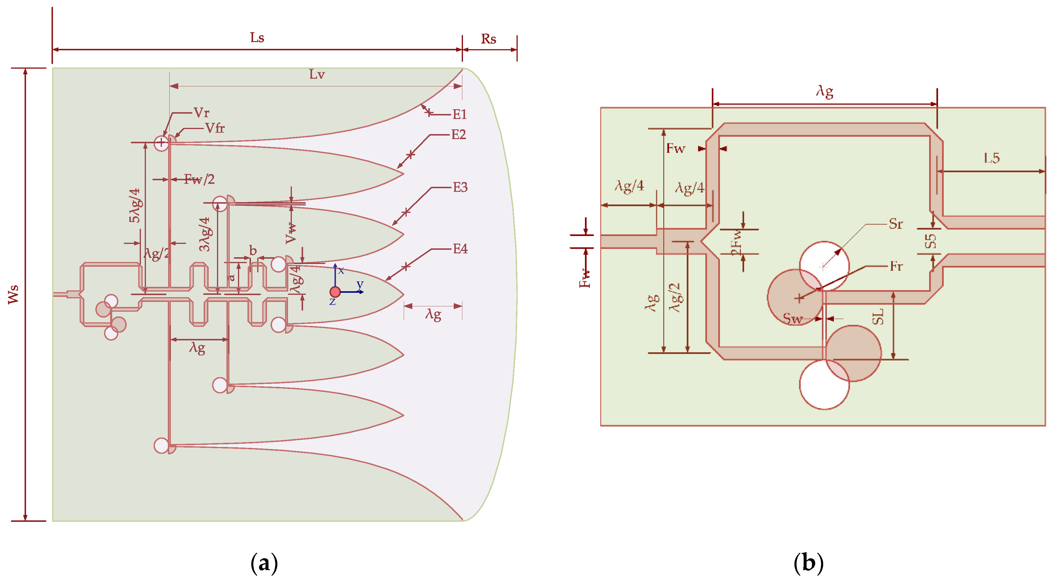
2. Antenna Design
2.1. Antenna Structure
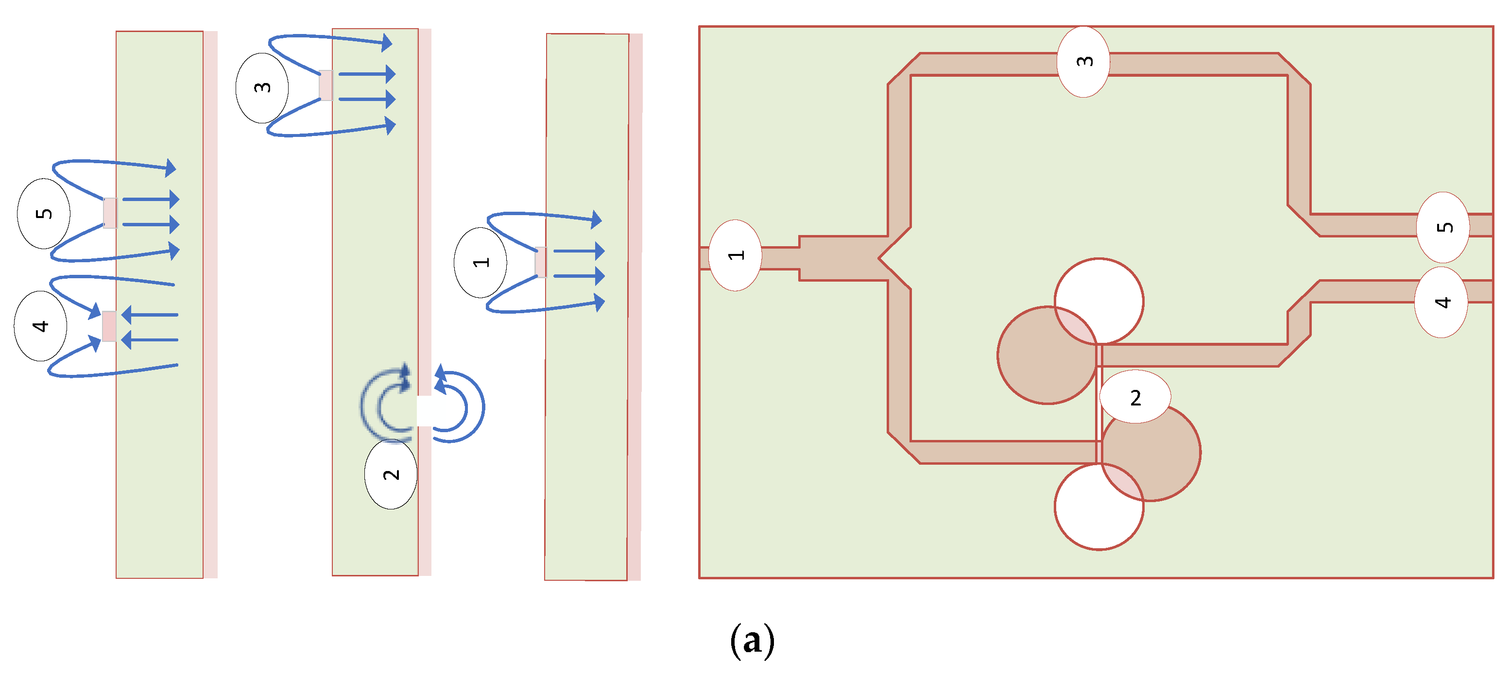
2.2. Design of Feeding Structure
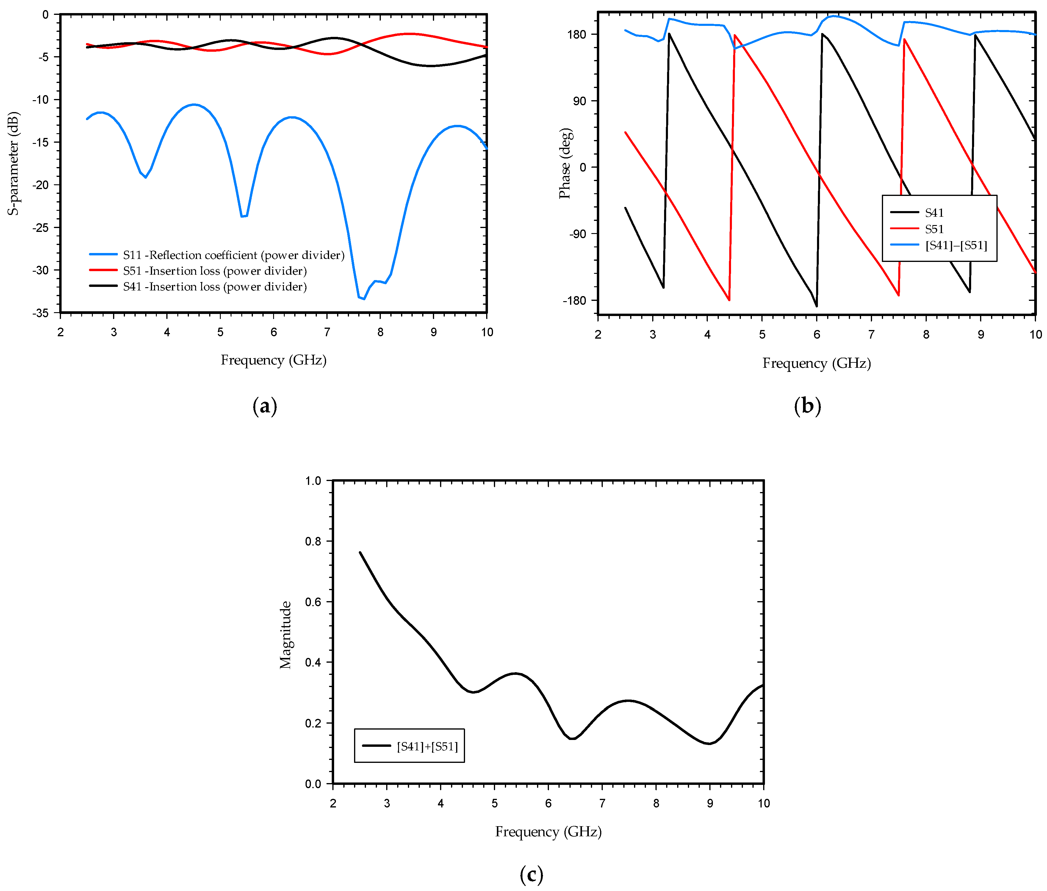
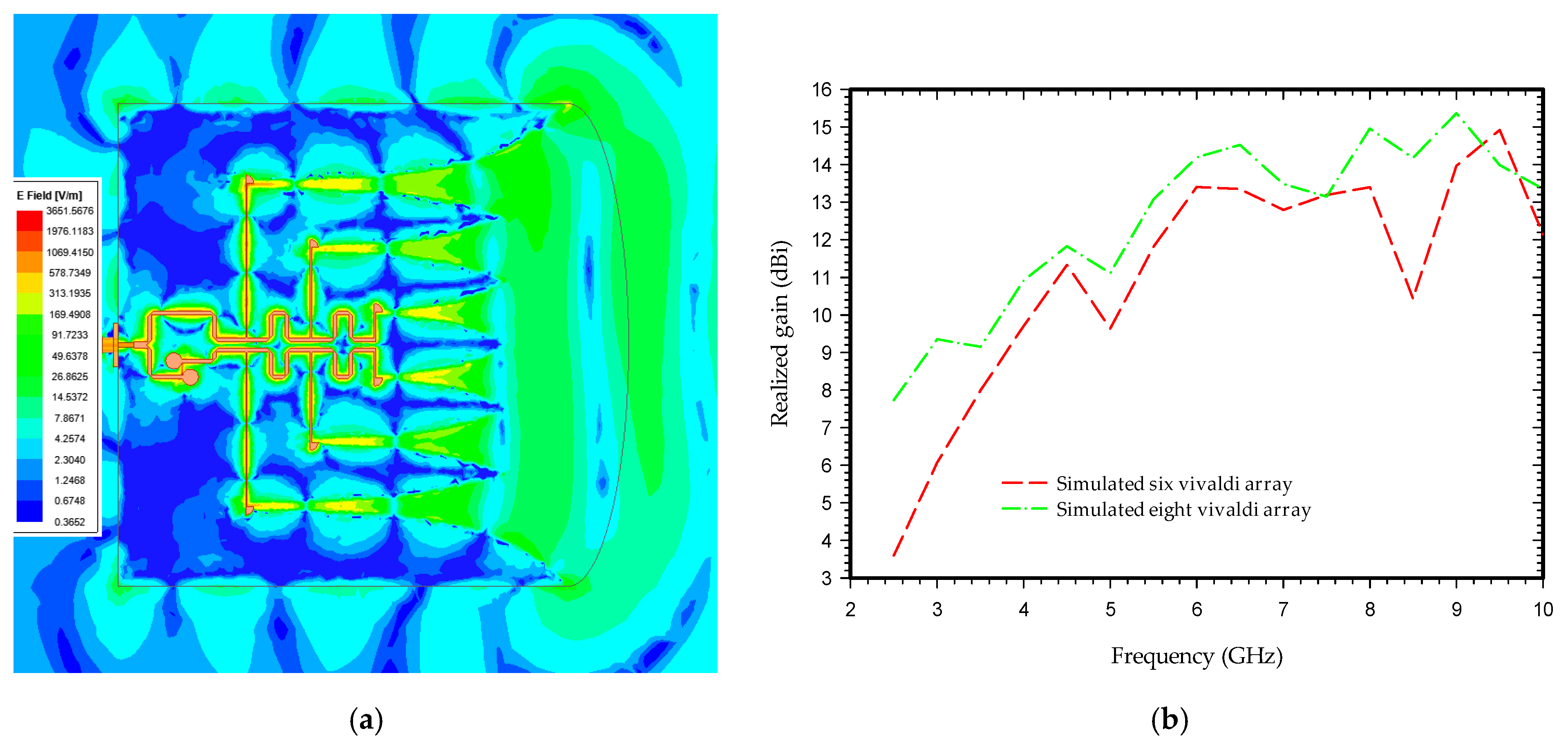
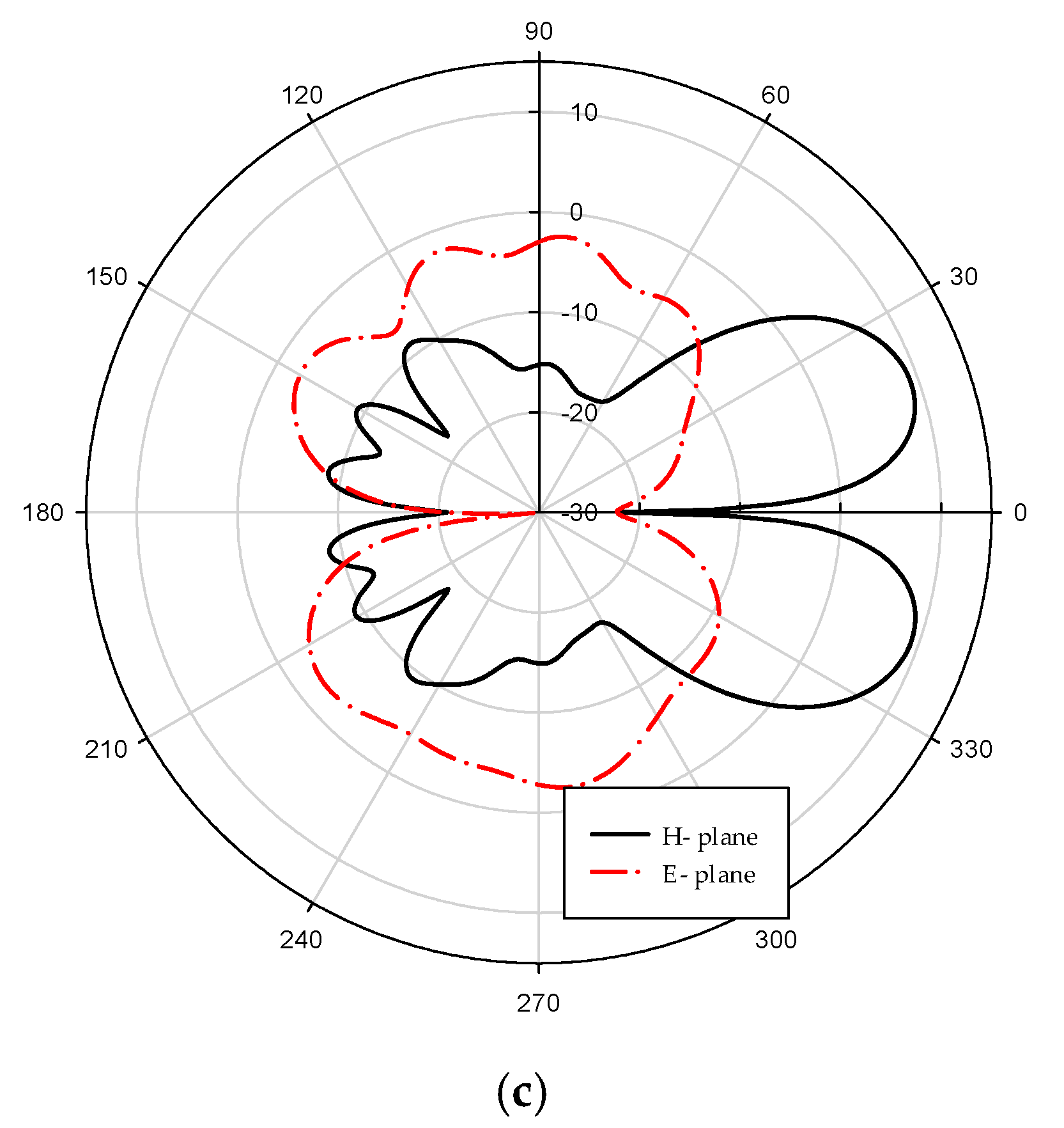
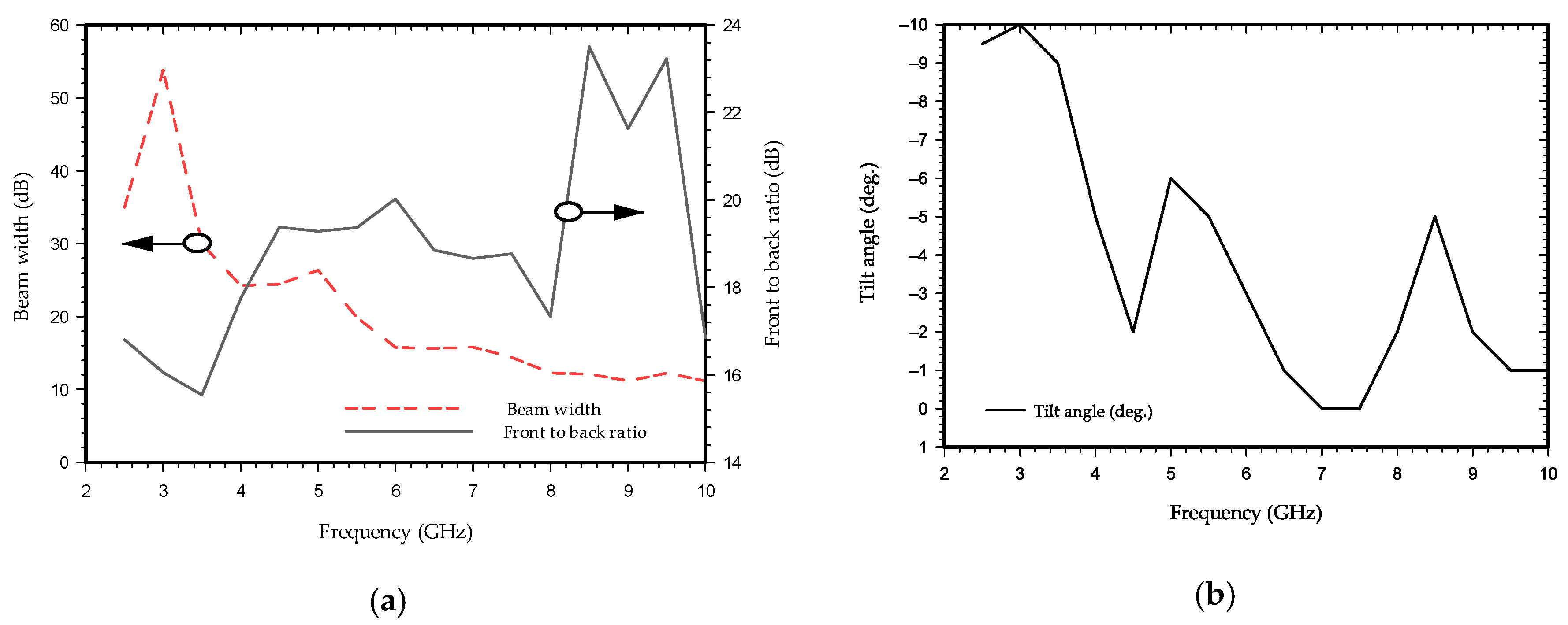
3. Results and Discussion
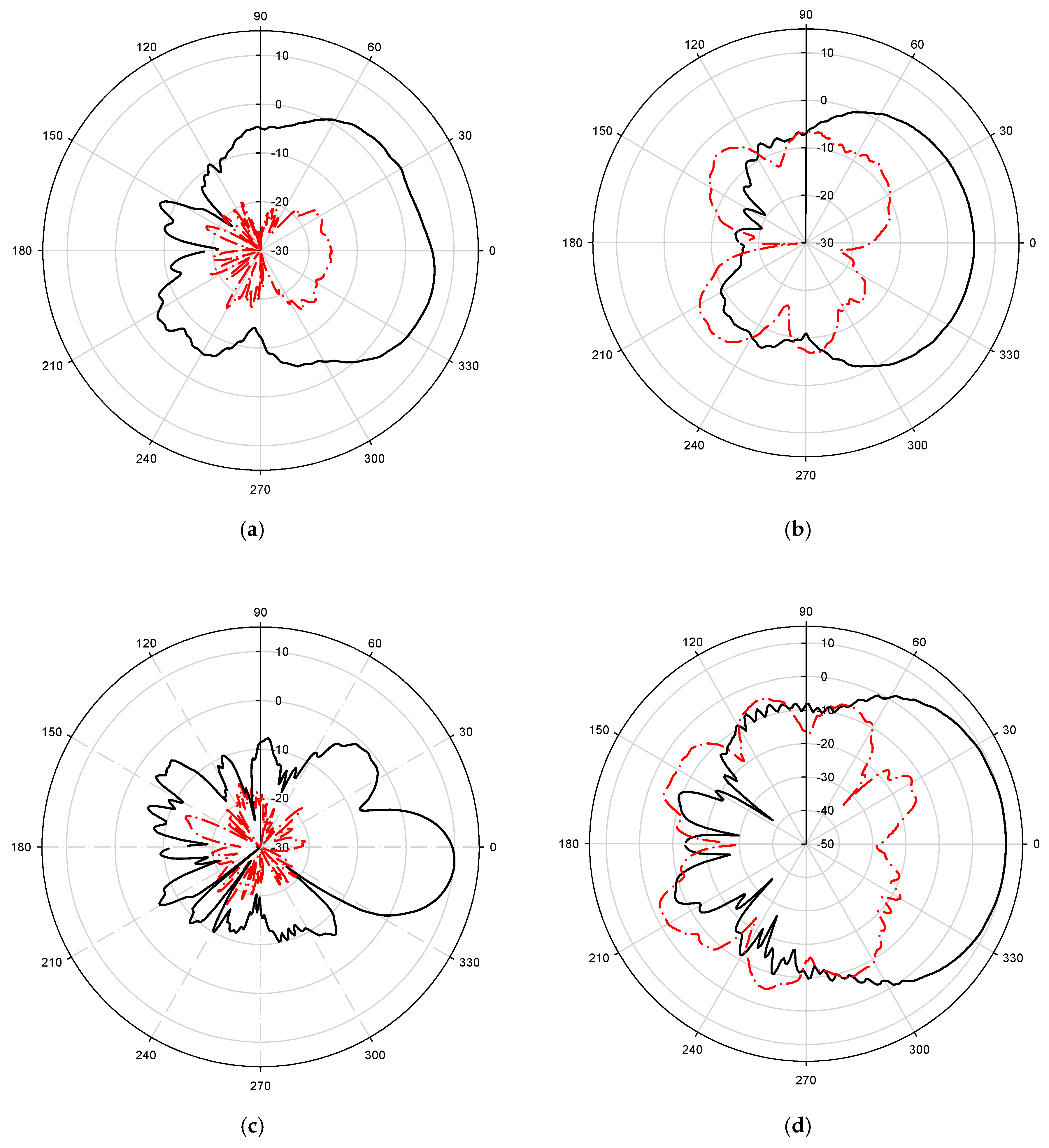
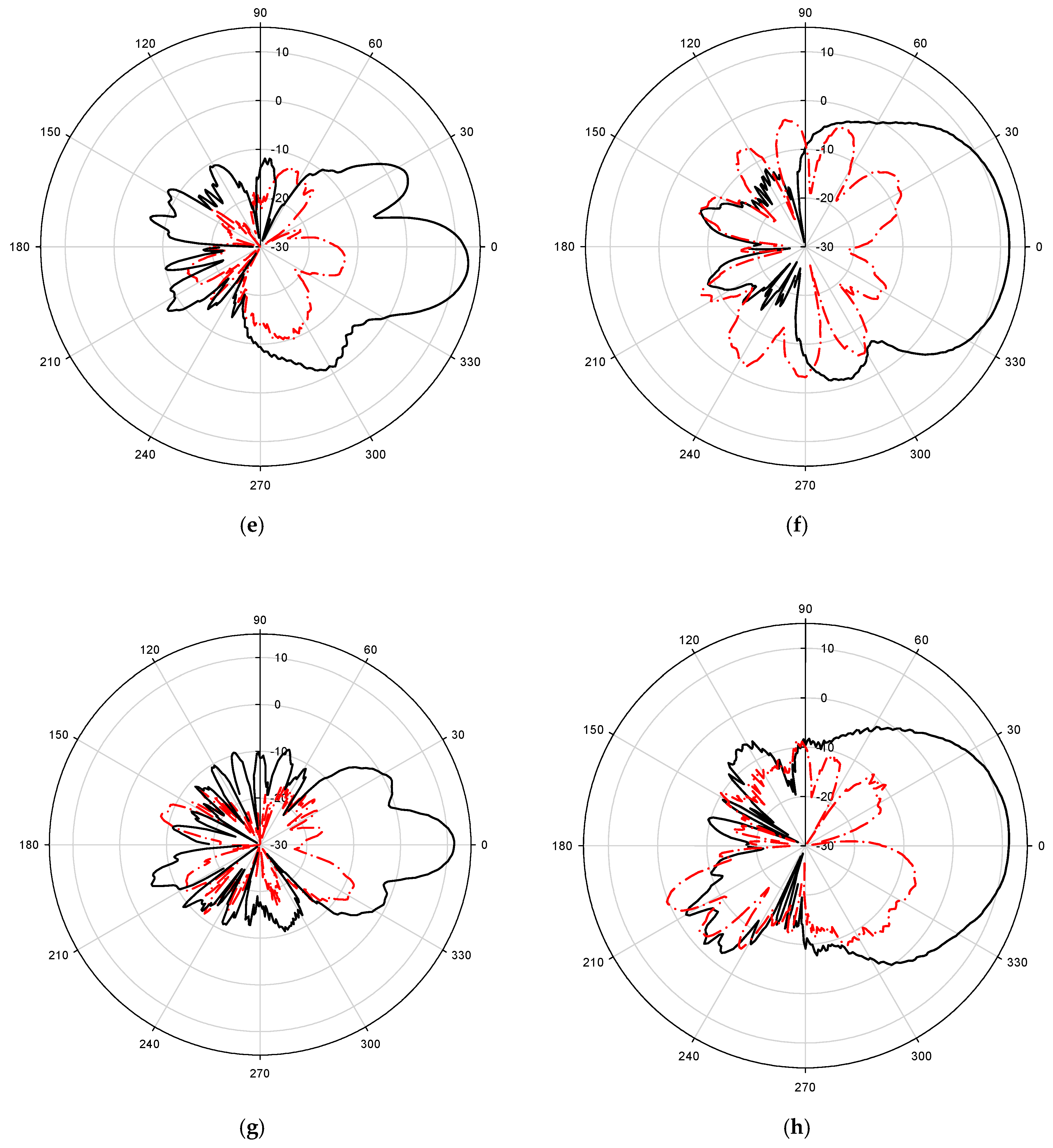
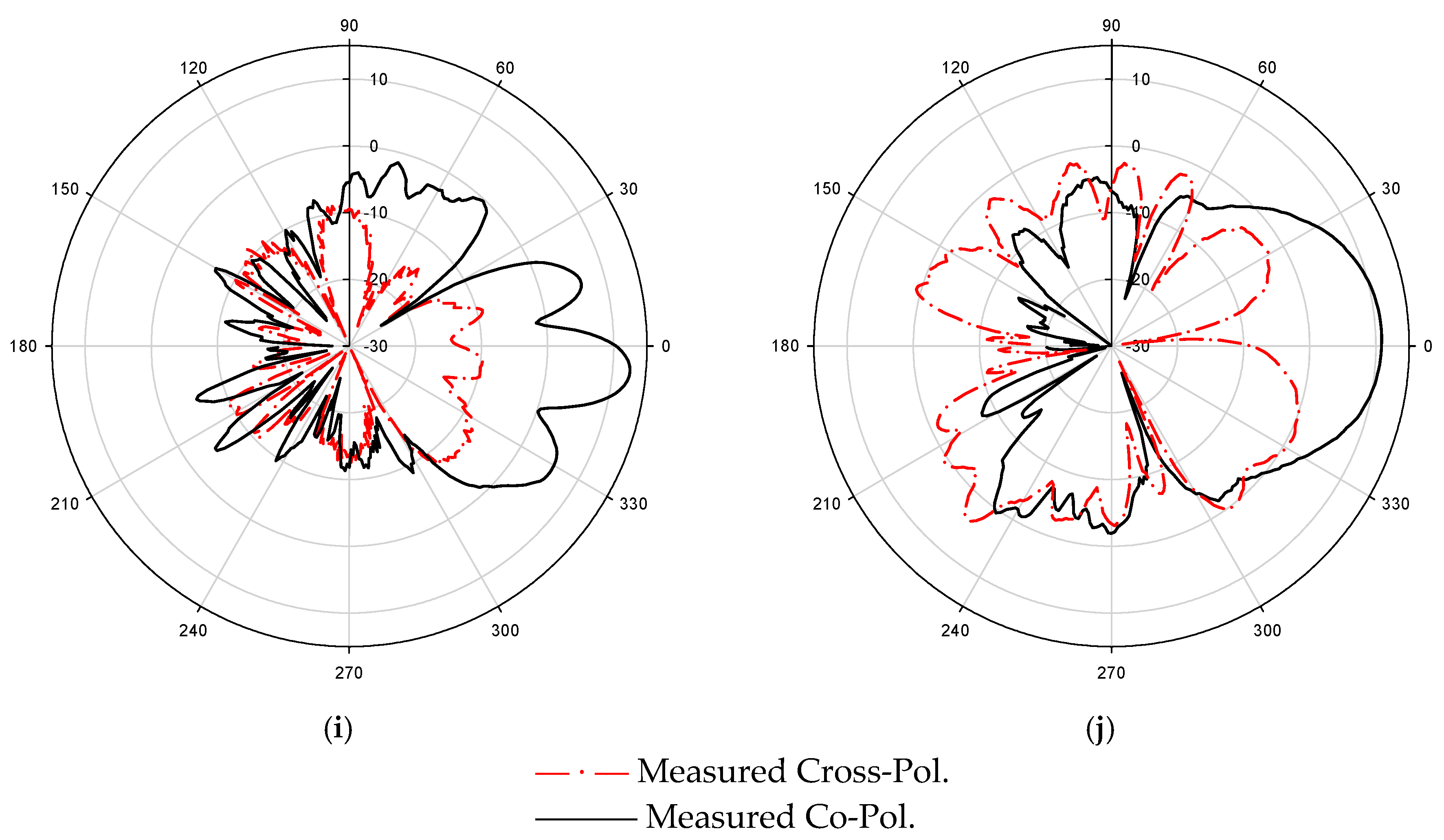
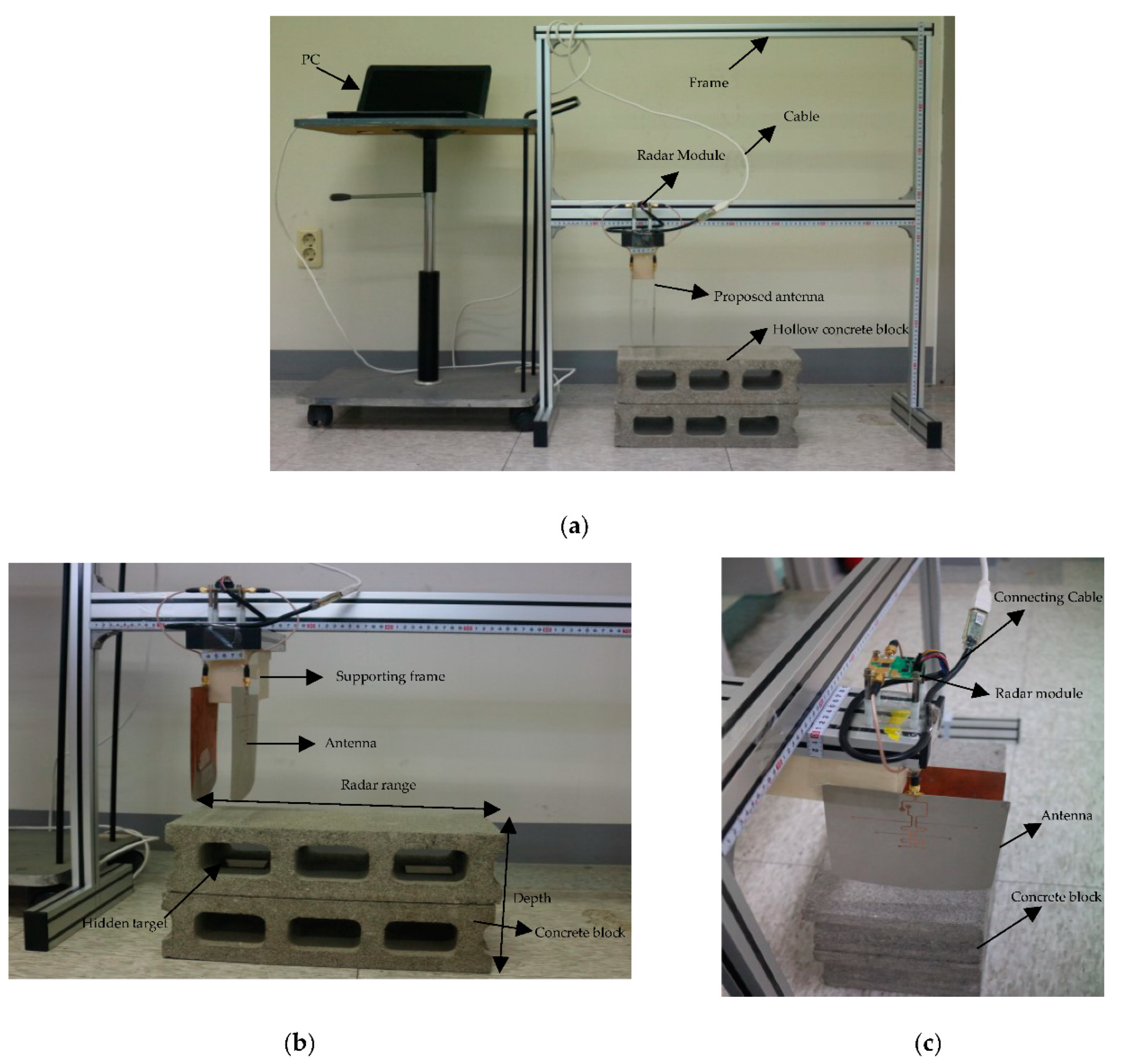
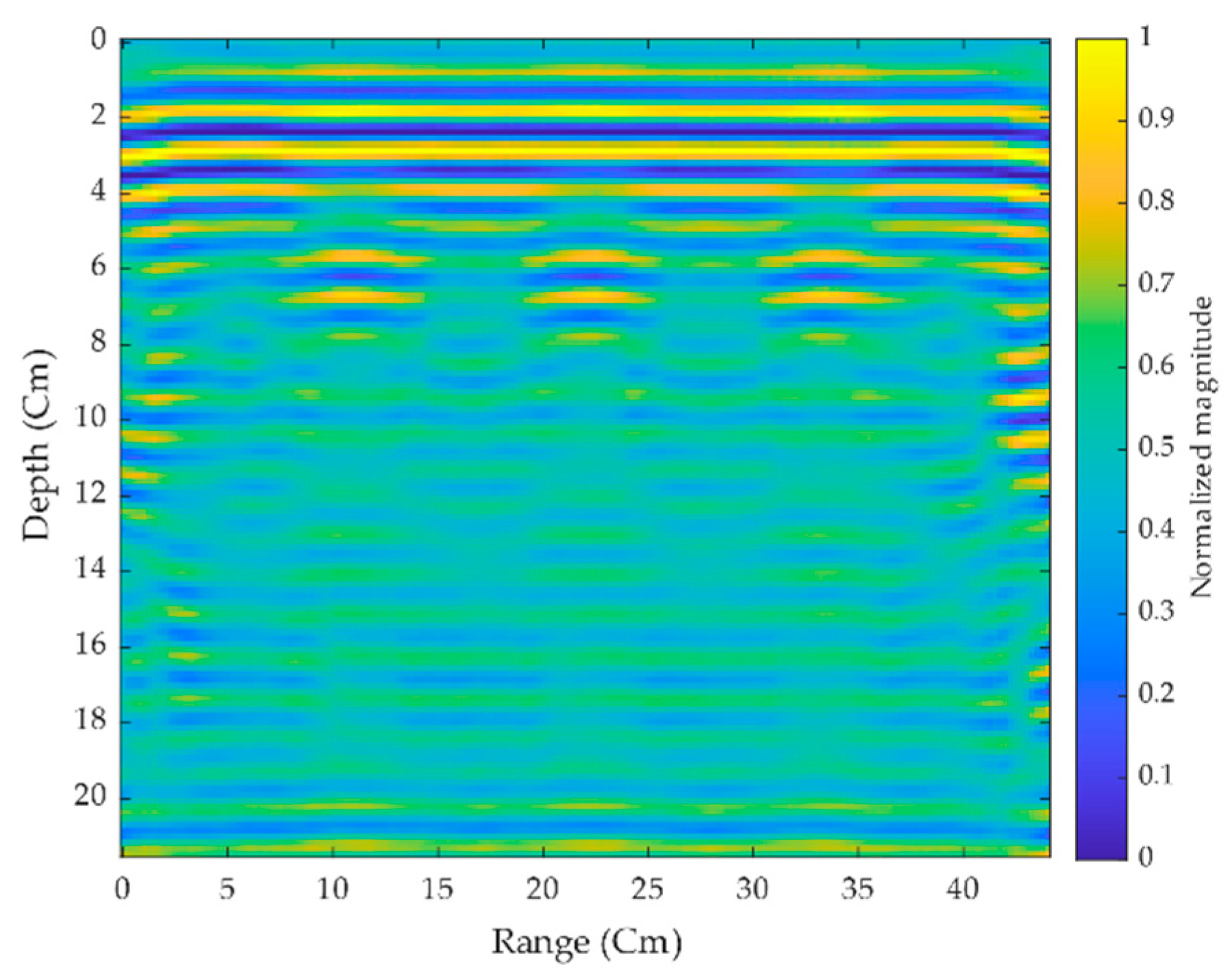
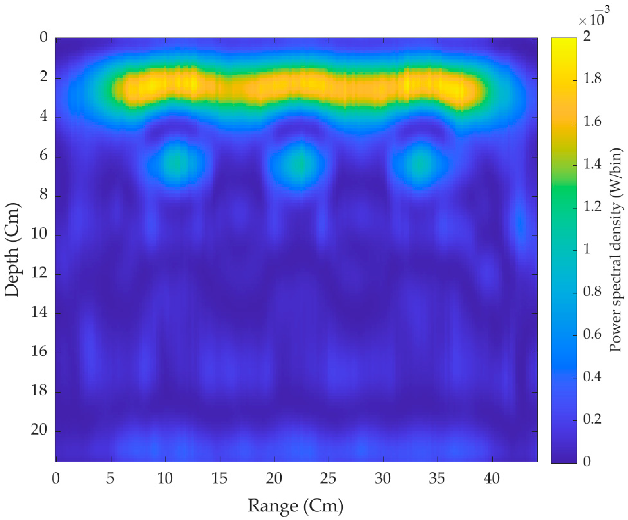
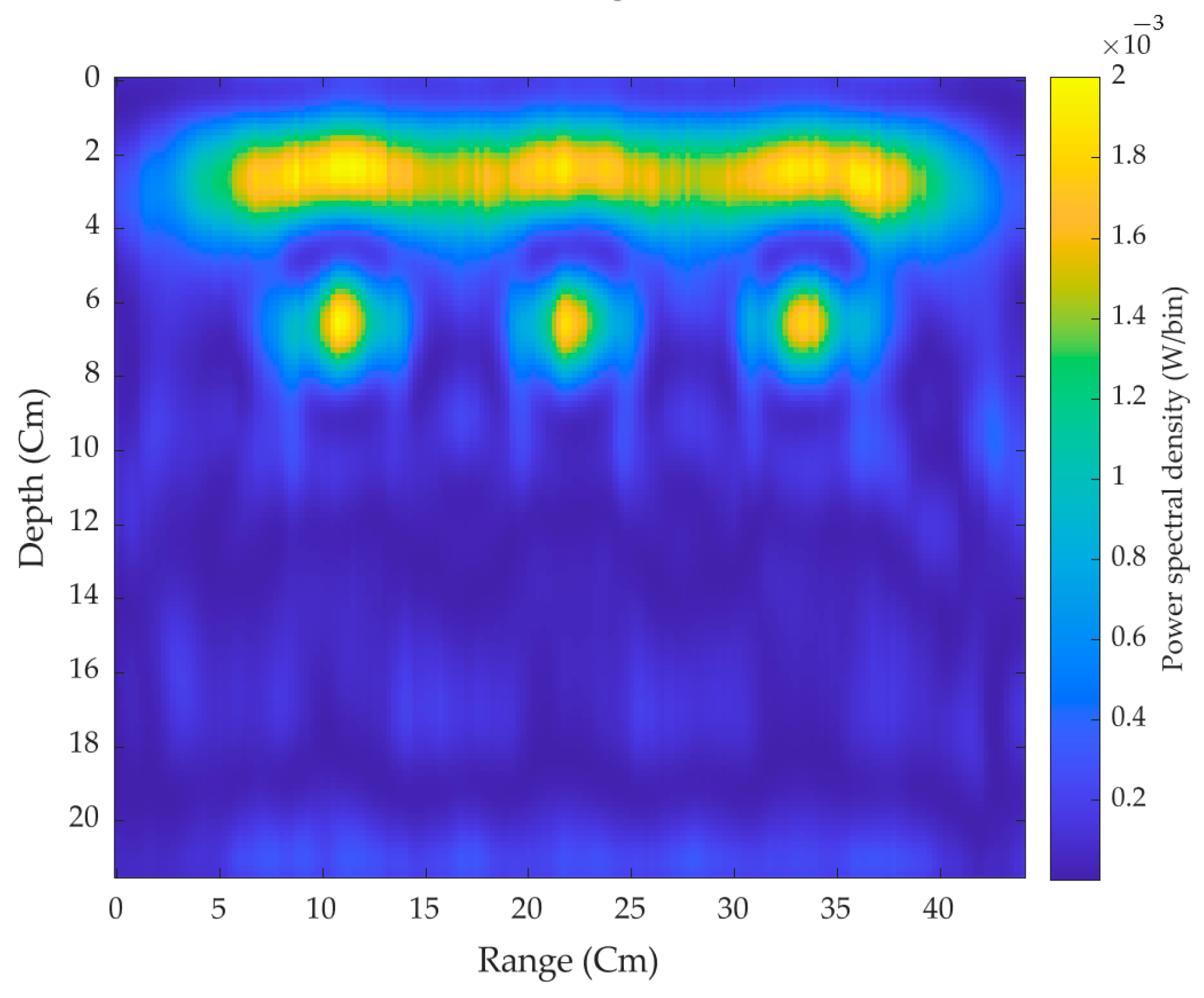
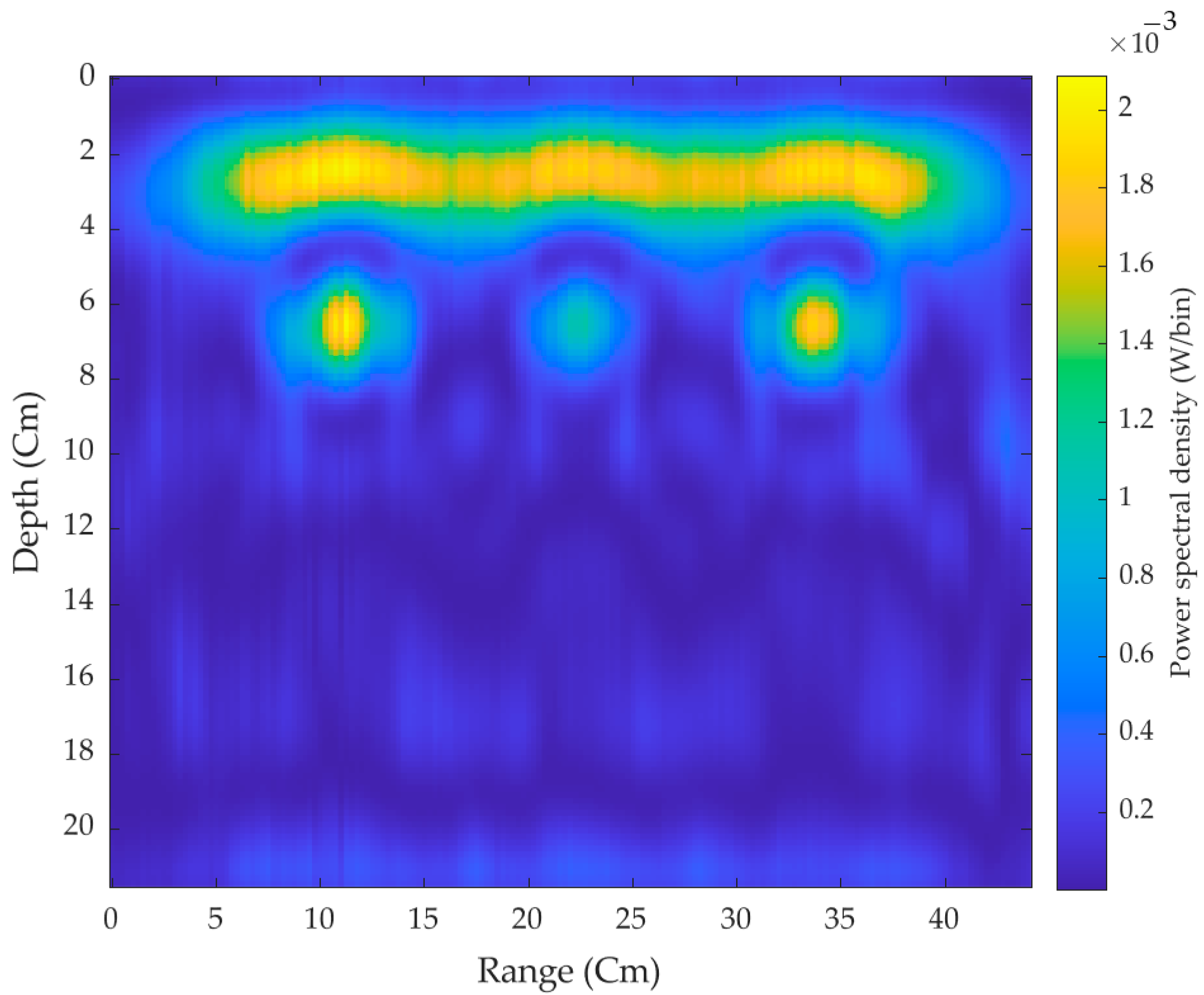
4. Experimental Study and Results
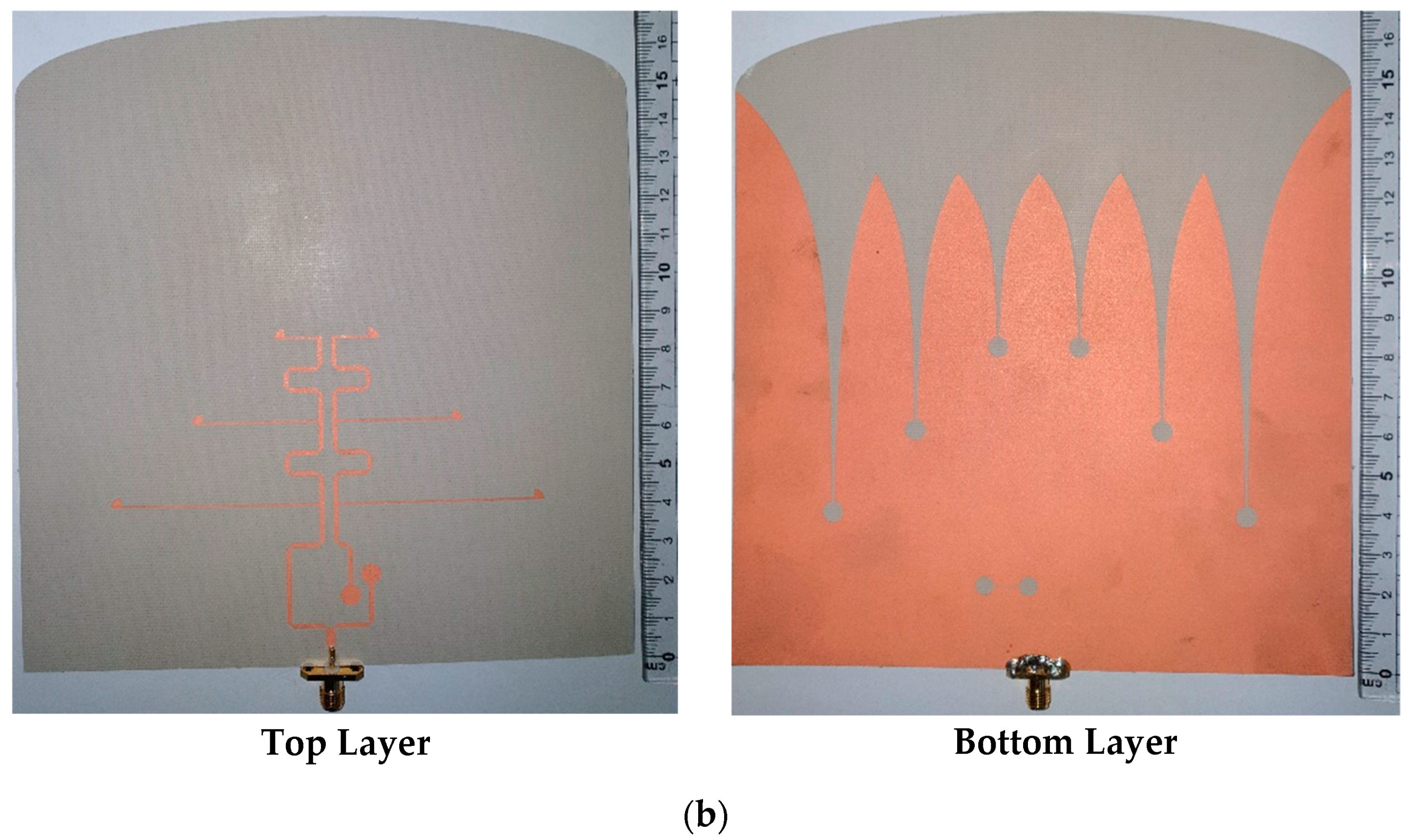
4.1. Specimens
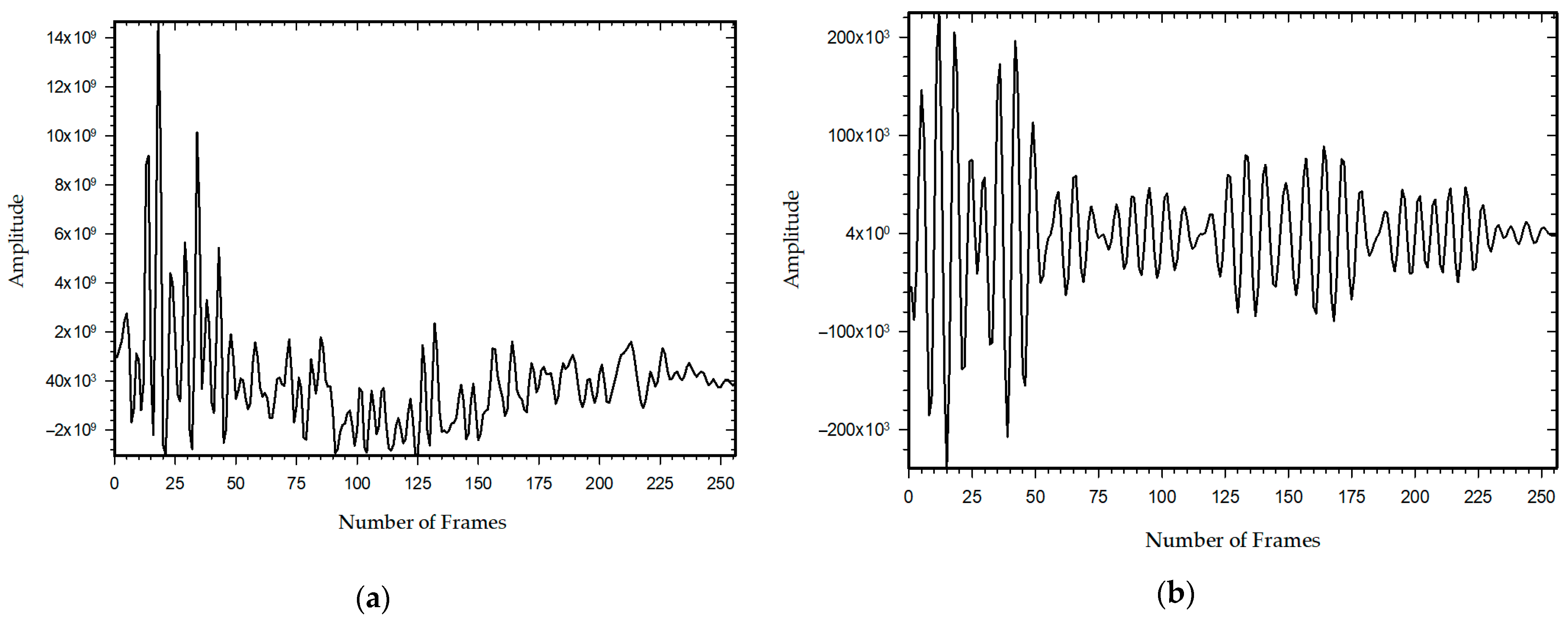
4.2. Signal Analyzing
4.3. Measurement Setup
5. Conclusions
Author Contributions
Funding
Institutional Review Board Statement
Informed Consent Statement
Data Availability Statement
Conflicts of Interest
References
- He, S.H.; Shan, W.; Fan, C.; Mo, Z.C.; Yang, F.H.; Chen, J.H. An improved vivaldi antenna for vehicular wireless communication systems. IEEE Antennas Wirel. Propag. Lett. 2014, 13, 1505–1508. [Google Scholar] [CrossRef]
- Reid, E.W.; Ortiz-Balbuena, L.; Ghadiri, A.; Moez, K. A 324-element vivaldi antenna array for radio astronomy instrumentation. IEEE Trans. Instrum. Meas. 2012, 61, 241–250. [Google Scholar] [CrossRef]
- Abbak, M.; Akinci, M.N.; Çayören, M.; Akduman, I. Experimental microwave imaging with a novel corrugated vivaldi antenna. IEEE Trans. Antennas Propag. 2017, 65, 3302–3307. [Google Scholar] [CrossRef]
- Pozar, D.M. Microstrip antennas. Proc. IEEE 1992, 80, 79–91. [Google Scholar] [CrossRef]
- Kumar, P.; Urooj, S. A miniaturized low-profile UWB antenna for microwave imaging applications. In Proceedings of the International Conference on Power Electronics, Control and Automation (ICPECA), New Delhi, India, 16–17 November 2019. [Google Scholar] [CrossRef]
- Zainud-Deen, S.; Badr, M.; Hassan, E.; Awadalla, K.; Sharshar, H. Microstrip antenna with defected ground plane structure as a sensor for landmines detection. Prog. Electromagn. Res. B 2008, 4, 27–39. [Google Scholar] [CrossRef] [Green Version]
- Elboushi, A.; Joanes, D.; Derbas, M.; Khaled, S.; Zafar, A.; Attabibi, S.; Sebak, A.R. Design of UWB antenna array for through-wall detection system. In Proceedings of the Symposium on Wireless Technology & Applications (ISWTA 2013), Kuching, Malaysia, 22–25 September 2013; pp. 349–354. [Google Scholar] [CrossRef]
- Inum, R.; Rana, M.M.; Shushama, K.N.; Quader, M.A. EBG based microstrip patch antenna for brain tumor detection via scattering parameters in microwave imaging system. Int. J. Biomed. Imaging 2018, 2018, 12. [Google Scholar] [CrossRef]
- Schires, E.; Georgiou, P.; Lande, T.S. Vital sign monitoring through the back using an UWB impulse radar with body coupled antennas. IEEE Trans. Biomed. Circuits Syst. 2018, 12, 292–302. [Google Scholar] [CrossRef]
- Pittella, E.; Bottiglieri, A.; Pisa, S.; Cavagnaro, M. Cardiorespiratory frequency monitoring using the principal component analysis technique on UWB radar signal. Int. J. Antennas Propag. 2017, 2017, 6. [Google Scholar] [CrossRef] [Green Version]
- Skaria, S.; Al-Hourani, A.; Evans, R.J. Deep-learning methods for hand-gesture recognition using ultra-wideband radar. IEEE Access 2020, 8, 203580–203590. [Google Scholar] [CrossRef]
- Moosazadeh, M.; Kharkovsky, S.; Case, J.T.; Samali, B. Antipodal Vivaldi antenna with improved radiation characteristics for civil engineering applications. IET Microw. Antennas Propag. 2017, 11, 796–803. [Google Scholar] [CrossRef]
- Xie, X.; Qin, H.; Yao, R. Design of an improved dipole antenna for detecting enclosure structure defects by crosshole GPR. In Proceedings of the 15th International Conference on Ground Penetrating Radar (GPR), Brussels, Belgium, 30 June–4 July 2014; pp. 723–727. [Google Scholar] [CrossRef]
- Wu, Y.; Shen, F.; Yuan, Y.; Xu, D. an improved modified universal ultra-wideband antenna designed for step frequency continuous wave ground penetrating radar system. Sensors 2019, 19, 1045. [Google Scholar] [CrossRef] [Green Version]
- Joula, M.; Rafiei, V.; Karamzadeh, S. High gain UWB bow-tie antenna design for ground penetrating radar application. Microw. Opt. Technol. Lett. 2018, 60, 2425–2429. [Google Scholar] [CrossRef]
- Richardson, M.; Bauder, C.J.; Kazemi, R.; Fathy, A.E. Design of a Rigid UWB Log Spiral Antenna for GPR Applications in Harsh Environment. In Proceedings of the IEEE Radio and Wireless Symposium (RWS), San Antonio, TX, USA, 26–29 January 2020; pp. 262–264. [Google Scholar] [CrossRef]
- Shao, J.; Fang, G.; Ji, Y.; Tan, K.; Yin, H. A novel compact tapered-slot antenna for GPR applications. IEEE Antennas Wirel. Propag. Lett. 2013, 12, 972–975. [Google Scholar] [CrossRef]
- Raza, A.; Lin, W.; Chen, Y.; Yanting, Z.; Chattha, H.T.; Sharif, A.B. Wideband tapered slot antenna for applications in ground penetrating radar. Microw. Opt. Technol. Lett. 2020, 62, 2562–2568. [Google Scholar] [CrossRef]
- Ahmed, A.; Zhang, Y.; Burns, D.; Huston, D.; Xia, T. Design of UWB antenna for air-coupled impulse ground-penetrating radar. IEEE Geosci. Remote Sens. Lett. 2016, 13, 92–96. [Google Scholar] [CrossRef]
- Turk, A.S.; Keskin, A.K. Vivaldi shaped TEM horn fed ridged horn antenna design for UWB GPR systems. In Proceedings of the 6th International Workshop on Advanced Ground Penetrating, Aachen, Germany, 22–24 June 2011. [Google Scholar] [CrossRef]
- Travassos, X.L.; Avila, S.L.; da S. Adriano, R.L.; Ida, N. A Review of ground penetrating radar antenna design and optimization. J. Microw. Optoelectron. Electromagn. Appl. 2018, 17, 385–402. [Google Scholar] [CrossRef] [Green Version]
- Marecos, V.; Solla, M.; Fontul, S.; Antunes, V. Assessing the pavement subgrade by combining different non-destructive methods. Constr. Build. Mater. 2017, 135, 76–85. [Google Scholar] [CrossRef] [Green Version]
- Gibson, P.J. Vivaldi aerial. In Proceedings of the European Microwave Conference, Brighton, UK, 17–20 September 1979; pp. 101–105. [Google Scholar]
- Adamu, S.A.; Masri, T.; Abidin, W.A.W.Z.; Ping, K.H. Review on gain and directivity enhancement techniques of vivaldi antennas. Int. J. Sci. Eng. Res. 2017, 8, 1919–1927. [Google Scholar]
- Fei, P.; Jiao, Y.C.; Hu, W.; Zhang, F.S. A miniaturized antipodal vivaldi antenna with improved radiation characteristics. IEEE Antennas Wirel. Propag. Lett. 2011, 10, 127–130. [Google Scholar] [CrossRef]
- Molaei, A.; Kaboli, M.; Mirtaheri, S.A.; Abrishamian, M.S. Dielectric lens balanced antipodal Vivaldi antenna with low cross-polarisation for ultra-wideband applications. IET Microw. Antennas Propag. 2014, 8, 1137–1142. [Google Scholar] [CrossRef]
- Baviskar, J.; Shah, A.; Mulla, A.; Baviskar, A.; Dave, P. Design and analysis of metamaterial lens incorporated ultra wide band (UWB) antenna. In Proceedings of the IEEE Aerospace Conference Proceedings, Big Sky, MT, USA, 4–11 March 2017. [Google Scholar]
- Cheng, H.; Yang, D.; Hua, L.; Wang, Y.; Yang, H.; Wu, J.; Li, Y. A compact antipodal Vivaldi antenna with metamaterial half-lens for beam control. J. Phys. D Appl. Phys. 2021, 54, 205104. [Google Scholar] [CrossRef]
- Eshtiaghi, R.; Nourinia, J.; Ghobadi, C. Electromagnetically coupled band-notched elliptical monopole antenna for UWB applications. IEEE Trans. Antennas Propag. 2010, 58, 1397–1402. [Google Scholar] [CrossRef]
- Chen, Q.; Zhang, H.; Zhang, X.; Jin, M.; Wang, W. Wideband RCS reduction of vivaldi antenna using electromagnetic band gap absorbing structure. In Proceedings of the 2017 International Symposium on Antennas and Propagation, ISAP, Phuket, Thailand, 30 October–2 November 2017. [Google Scholar] [CrossRef]
- Bourqui, J.; Okoniewski, M.; Fear, E.C. Balanced antipodal vivaldi antenna with dielectric director for near-field microwave imaging. IEEE Trans. Antennas Propag. 2010, 58, 2318–2326. [Google Scholar] [CrossRef]
- Elsherbini, A.; Zhang, C.; Lin, S.; Kuhn, M.; Kamel, A.; Fathy, A.E.; Elhennawy, H. UWB antipodal vivaldi antennas with protruded dielectric rods for higher gain, symmetric patterns and minimal phase center variations. In Proceedings of the IEEE Antennas and Propagation Society, AP-S International Symposium (Digest), Honolulu, HI, USA, 10–15 June 2007; pp. 1973–1976. [Google Scholar]
- De Oliveira, A.M.; Perotoni, M.B.; Kofuji, S.T.; Justo, J.F. A palm tree antipodal vivaldi antenna with exponential slot edge for improved radiation pattern. IEEE Antennas Wirel. Propag. Lett. 2015, 14, 1334–1337. [Google Scholar] [CrossRef]
- Ur Rahman, M.; Naghshvarianjahromi, M.; Mirjavadi, S.S.; Hamouda, A.M. Bandwidth enhancement and frequency scanning array antenna using novel UWB filter integration technique for OFDM UWB radar applications in wireless vital signs monitoring. Sensors 2018, 18, 3155. [Google Scholar] [CrossRef] [PubMed] [Green Version]
- Ardelina, N.; Setijadi, E.; Mukti, P.H.; Manhaval, B. Comparison of array configuration for Antipodal Vivaldi antenna. In Proceedings of the International Conference on Radar, Antenna, Microwave, Electronics, and Telecommunications, ICRAMET, Bandung, Indonesia, 5–7 October 2015; pp. 40–45. [Google Scholar]
- Islam, M.; Islam, M.; Samsuzzaman, M.; Faruque, M.; Misran, N. A negative index metamaterial-inspired UWB antenna with an integration of complementary SRR and CLS unit cells for microwave imaging sensor applications. Sensors 2015, 15, 11601–11627. [Google Scholar] [CrossRef] [Green Version]
- Zhou, B.; Cui, T.J. Directivity enhancement to vivaldi antennas using compactly anisotropic zero-index metamaterials. IEEE Antennas Wirel. Propag. Lett. 2011, 10, 326–329. [Google Scholar] [CrossRef]
- Li, X.X.; Pang, D.W.; Wang, H.L.; Zhang, Y.M.; Lv, G.Q. Dielectric slabs covered broadband Vivaldi antenna for gain enhancement. Prog. Electromagn. Res. C 2017, 77, 69–80. [Google Scholar] [CrossRef] [Green Version]
- Schaubert, D.H.; Kasturi, S.; Boryssenko, A.O.; Elsallal, W.M. Vivaldi antenna arrays for wide bandwidth and electronic scanning. In Proceedings of the IET Seminar Digest, Edinburgh, Scotland, 11–16 November 2007; Volume 2007. [Google Scholar]
- Yngvesson, K.S.; Schaubert, D.H.; Korzeniowski, T.L.; Kollberg, E.L.; Thungren, T.; Johansson, J.F. Endfire tapered slot antennas on dielectric substrates. IEEE Trans. Antennas Propag. 1985, 33, 1392–1400. [Google Scholar] [CrossRef]
- Yngvesson, K.S.; Korzeniowski, T.L.; Kim, Y.S.; Kollberg, E.L.; Johansson, J.F. The tapered slot antenna—A new integrated element for millimeter-wave applications. IEEE Trans. Microw. Theory Tech. 1989, 37, 365–374. [Google Scholar] [CrossRef]
- Chen, X.P.; Li, L.; Wu, K. Multi-antenna system based on substrate integrated waveguide for Ka-band traffic-monitoring radar applications. In Proceedings of the European Microwave Week 2009, EuMW 2009: Science, Progress and Quality at Radiofrequencies, 39th European Microwave Conference, EuMC, Rome, Italy, 29 September–1 October 2009; pp. 417–420. [Google Scholar]
- Wang, H.; Fang, D.G.; Zhang, B.; Che, W.Q. Dielectric loaded substrate integrated waveguide (SIW) H-plane horn antennas. IEEE Trans. Antennas Propag. 2010, 58, 640–647. [Google Scholar] [CrossRef]
- Hao, Z.C.; Hong, W.; Li, H.; Zhang, H.; Wu, K. Multiway broadband substrate integrated waveguide (SIW) power divider. In Proceedings of the IEEE Antennas and Propagation Society, AP-S International Symposium (Digest), Honolulu, HI, USA, 10 June 2007; Volume 1A, pp. 639–642. [Google Scholar]
- Yang, S.; Elsherbini, A.; Lin, S.; Fathy, A.E.; Kamel, A.; Elhennawy, H. A highly efficient vivaldi antenna array design on thick substrate and fed by SIW structure with integrated GCPW feed. In Proceedings of the IEEE Antennas and Propagation Society, AP-S International Symposium (Digest), Honolulu, HI, USA, 10 June 2007; pp. 1985–1988. [Google Scholar]
- Kazemi, R.; Fathy, A.E.; Sadeghzadeh, R.A. Ultra-wide band vivaldi antenna array using low loss SIW power divider and GCPW wide band transition. In Proceedings of the RWW: IEEE Radio and Wireless Symposium, RWS, Santa Clara, CA, USA, 15–18 January 2012; pp. 39–42. [Google Scholar]
- Zhu, S.; Liu, H.; Chen, Z.; Wen, P. A compact gain-enhanced vivaldi antenna array with suppressed mutual coupling for 5G mmwave application. IEEE Antennas Wirel. Propag. Lett. 2018, 17, 776–779. [Google Scholar] [CrossRef]
- Kazemi, R.; Fathy, A.E. Design of single-ridge SIW power dividers with over 75% bandwidth. In Proceedings of the IEEE MTT-S International Microwave Symposium Digest, Tampa, FL, USA, 1–6 June 2014. [Google Scholar]
- Kordiboroujeni, Z.; Bornemann, J. Efficient design of Substrate Integrated Waveguide power dividers for antenna feed systems. In Proceedings of the 7th European Conference on Antennas and Propagation, EuCAP, Gothenburg, Sweden, 8–12 April 2013; pp. 352–356. [Google Scholar]
- Ullah, R.; Ullah, S.; Faisal, F.; Ullah, R.; Choi, D.; Ahmad, A.; Kamal, B. High-gain vivaldi antenna with wide bandwidth characteristics for 5G mobile and Ku-Band radar applications. Electronics 2021, 10, 667. [Google Scholar] [CrossRef]
- Wang, Z.; Liu, H.; Yang, W.; Wang, Y.; Zhu, S.; Wen, P. Bandwidth- and Gain-Enhanced Vivaldi Antenna Array Fed by Non-uniform T-junction Power Divider for Radio Astronomy Application. In Proceedings of the 12th International Symposium on Antennas, Propagation and EM Theory, Hangzhou, China, 3–6 December 2018. [Google Scholar] [CrossRef]
- Yang, Y.; Wang, Y.; Fathy, A. Design of Compact Vivaldi Antenna Arrays for UWB see through wall applications. Prog. Electromagn. Res. 2008, 82, 401–418. [Google Scholar] [CrossRef] [Green Version]
- Akhter, Z.; Kumar, P.; Akhtar, M.J. Sub-surface microwave imaging using four-slot vivaldi antenna with improved directivity. Frequenz 2017, 71, 19–28. [Google Scholar] [CrossRef]
- Bialkowski, M.E.; Abbosh, A.M. Design of a compact UWB out-of-phase power divider. IEEE Microw. Wirel. Compon. Lett. 2007, 17, 289–291. [Google Scholar] [CrossRef]
- Tebache, S.; Ghanem, F.; Belouchrani, A.; Mansoul, A. Novel flowchart design of frequency independent 180° phase shifters. Microw. Opt. Technol. Lett. 2019, 61, 136–140. [Google Scholar] [CrossRef] [Green Version]
- Bai, J.; Shi, S.; Prather, D.W. Ultra-wideband slot-loaded antipodal Vivaldi antenna array. In Proceedings of the IEEE Antennas and Propagation Society, AP-S International Symposium, Spokane, WC, USA, 3–8 July 2011; pp. 79–81. [Google Scholar] [CrossRef]
- Safitri, N.; Astuti, R.P.; Nugroho, B.S. Switch-Beam Vivaldi Array Antenna Based On 4x4 Butler Matrix for mmWave. MATEC Web Conf. 2018, 218, 03011. [Google Scholar] [CrossRef] [Green Version]
- XETHRU by NOVELDA. X2 Impulse Radar Transceiver; NOVELDA: Oslo, Norway, 2015. [Google Scholar]


| Parameter | mm | Parameter | mm |
|---|---|---|---|
| Fw | 1.2 | Sw | 0.3 |
| λg | 21.1 | Vw | 0.3 |
| Rs | 0.125 × Ws | Sl | λg/2 |
| Sr | λg/8 | S5 | 2 × Fw |
| Fr | λg/8 | L5 | 10.25 |
| Vr | λg/8 | Ls | 147.7 |
| Vfr | λg/8 | Ws | 158.25 |
| Lv | 4 × λg | a+b | λg/4 |
| Ref. | Number of Vivaldi Antenna Elements | Frequency Range (GHz) | Feed System | Gain (dBi) |
|---|---|---|---|---|
| [45] | 8 | 9–11 | T-junction power divider and GCPW transition | 12 |
| [47] | 8 | 24.75–28.5 | T-junction power divider | 6.96–11.32 |
| [51] | 4 | 1–6 | T-junction power divider | 5.7–11.3 |
| [53] | 4 | 2–11 | V-shaped power divider with T-junction | 3.75–11 |
| [57] | 4 | 25–31 | 4 4 butler matrix | 10.2 |
| Proposed antenna | 6 | 2.5–6.8 and 7.5–9.5 | T-junction power divider with independent phase shifter | 3.2–14.12 |
Publisher’s Note: MDPI stays neutral with regard to jurisdictional claims in published maps and institutional affiliations. |
© 2021 by the authors. Licensee MDPI, Basel, Switzerland. This article is an open access article distributed under the terms and conditions of the Creative Commons Attribution (CC BY) license (https://creativecommons.org/licenses/by/4.0/).
Share and Cite
Ghimire, J.; Diba, F.D.; Kim, J.-H.; Choi, D.-Y. Vivaldi Antenna Arrays Feed by Frequency-Independent Phase Shifter for High Directivity and Gain Used in Microwave Sensing and Communication Applications. Sensors 2021, 21, 6091. https://0-doi-org.brum.beds.ac.uk/10.3390/s21186091
Ghimire J, Diba FD, Kim J-H, Choi D-Y. Vivaldi Antenna Arrays Feed by Frequency-Independent Phase Shifter for High Directivity and Gain Used in Microwave Sensing and Communication Applications. Sensors. 2021; 21(18):6091. https://0-doi-org.brum.beds.ac.uk/10.3390/s21186091
Chicago/Turabian StyleGhimire, Jiwan, Feyisa Debo Diba, Ji-Hoon Kim, and Dong-You Choi. 2021. "Vivaldi Antenna Arrays Feed by Frequency-Independent Phase Shifter for High Directivity and Gain Used in Microwave Sensing and Communication Applications" Sensors 21, no. 18: 6091. https://0-doi-org.brum.beds.ac.uk/10.3390/s21186091