
Two-Dimensional Cartesian Coordinate System Educational Toolkit: 2D-CACSET

 ,
,  ,
,  ,
,  and
and
Abstract
:1. Introduction
2. Related Work
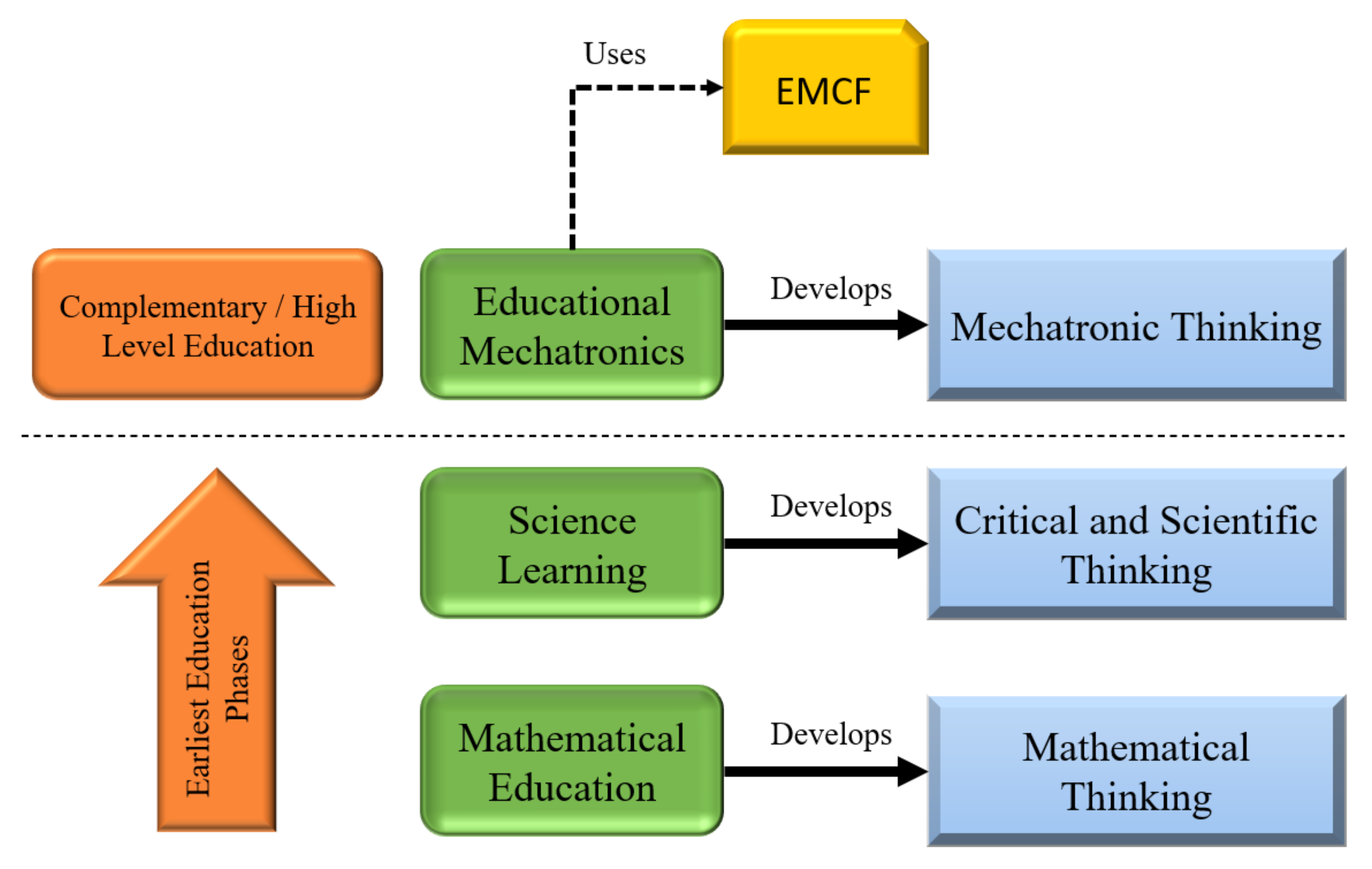
3. Educational Mechatronics Conceptual Framework EMCF
4. 2D-CACSET Two-Dimensional Cartesian Coordinate System Educational Toolkit
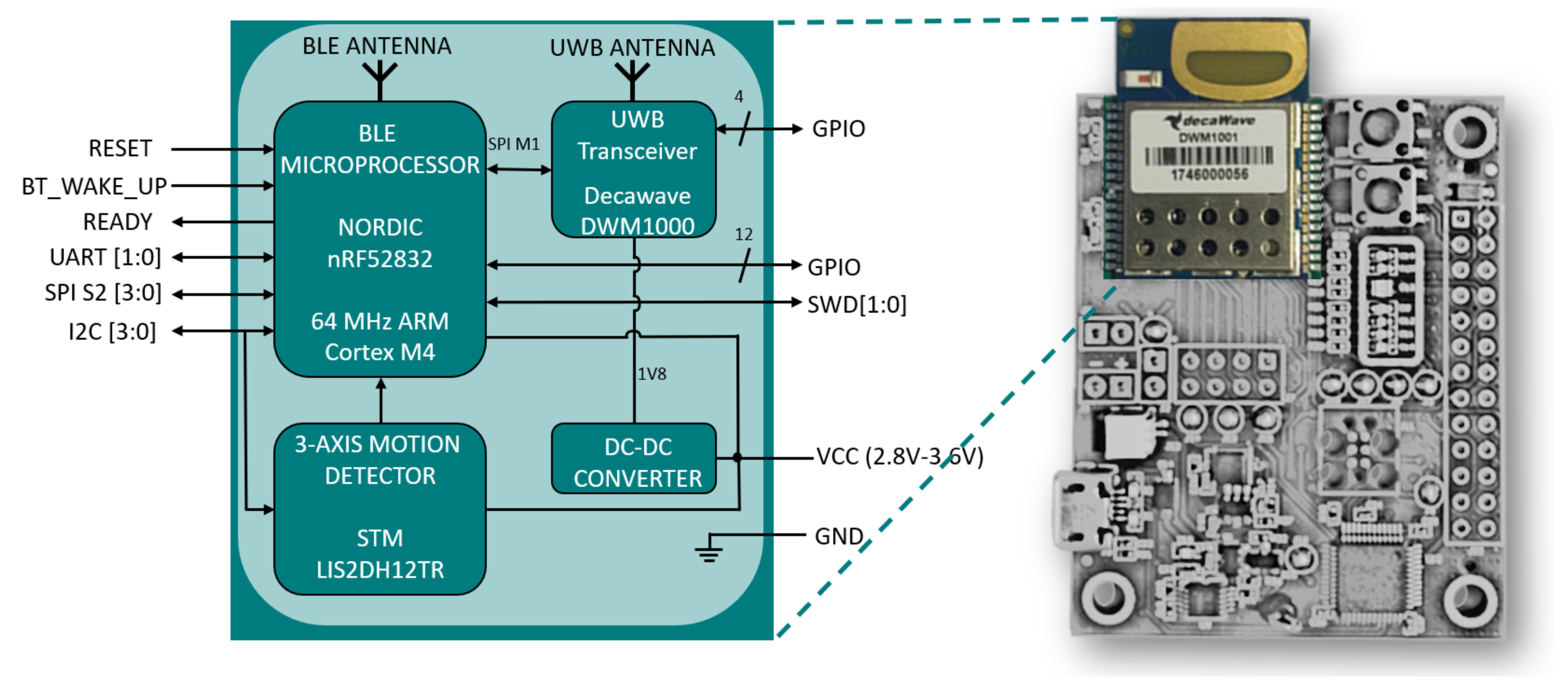
- Microprocessor nRF52832: Ultra-Low Power System on Chip (SoC) integrates Bluetooth Low Energy. Its processor is based on an Advanced RISC Machines (ARM) Cortex-M4 architecture and contains 64 kB of RAM and 512 kB of ROM. An exciting microprocessor feature is that it allows code debugging, which provides a good development environment for programmers and developers.
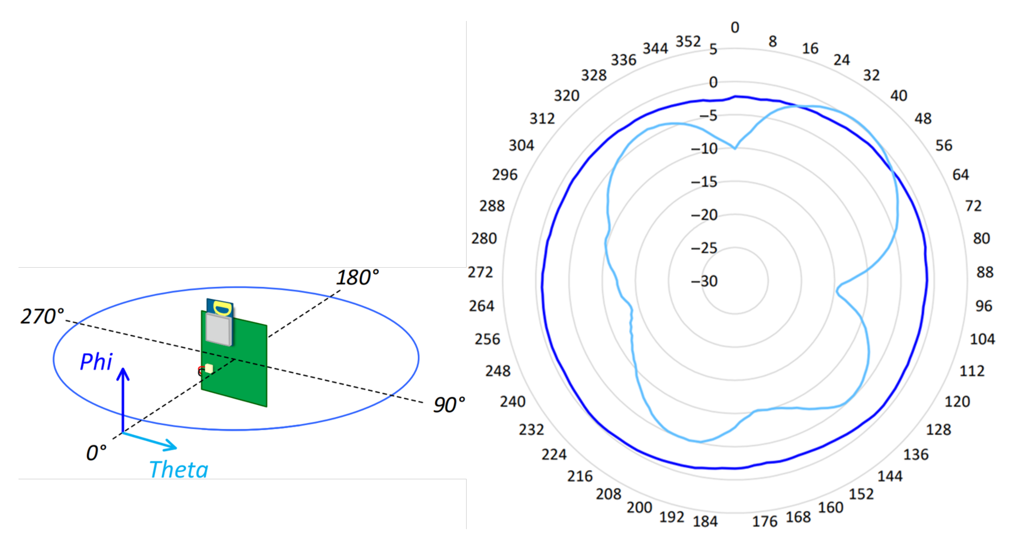
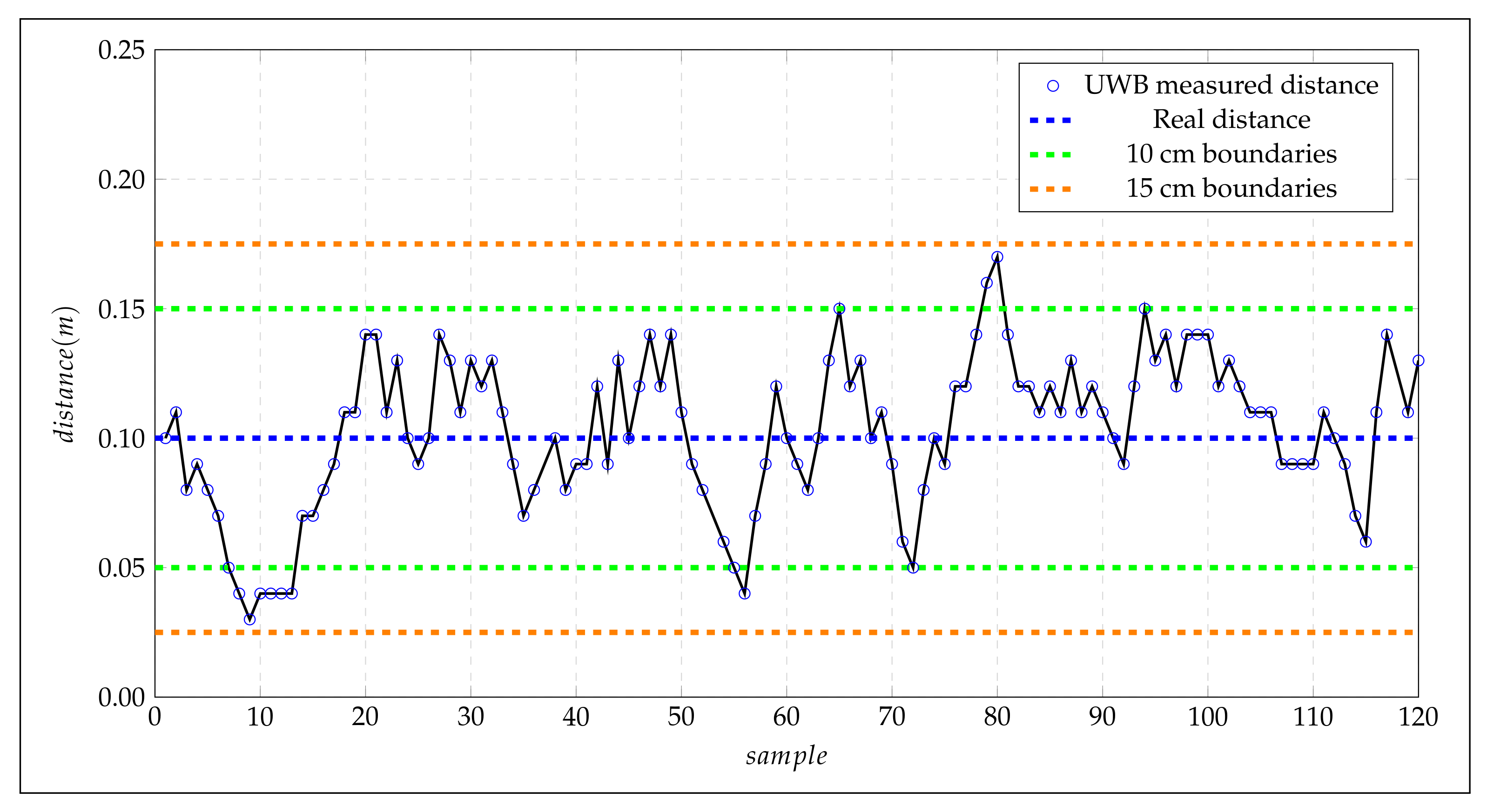
- DW1000 Ultra-Wideband (UWB) Transceiver: It is the physical layer based on IEEE 802.15. 4-2011, the DW1000 supports two multilateration algorithms, Two Way Ranging (TWR) and Time Differential on Arrival (TDoA), and boasts an accuracy of 10 cm in line-of-sight (LOS) applications. It works in the frequency range of 3.5 GHz to 6.5 GHz. This module is controlled through the Serial Peripheral Interface (SPI). For ease of use, the manufacturer provides a library to control the different peripherals contained in the module.
- LIS2DH12 3-axis linear accelerometer: This I2C accelerometer has a selectable scale range of +/−2 g, +/−4 g, +/−8 g, and +/−16 g at sampling rates from 1 Hz to 5.3 kHz. It bears a self-test capability that allows the user to verify the sensor’s functionality. In addition, the device can be configured to generate interrupt signals when it detects inertial free-fall events and the position of the device itself.
- Step-down converter: This converter provides an output voltage of 1.8, which is required by the DWM1000 transceiver.
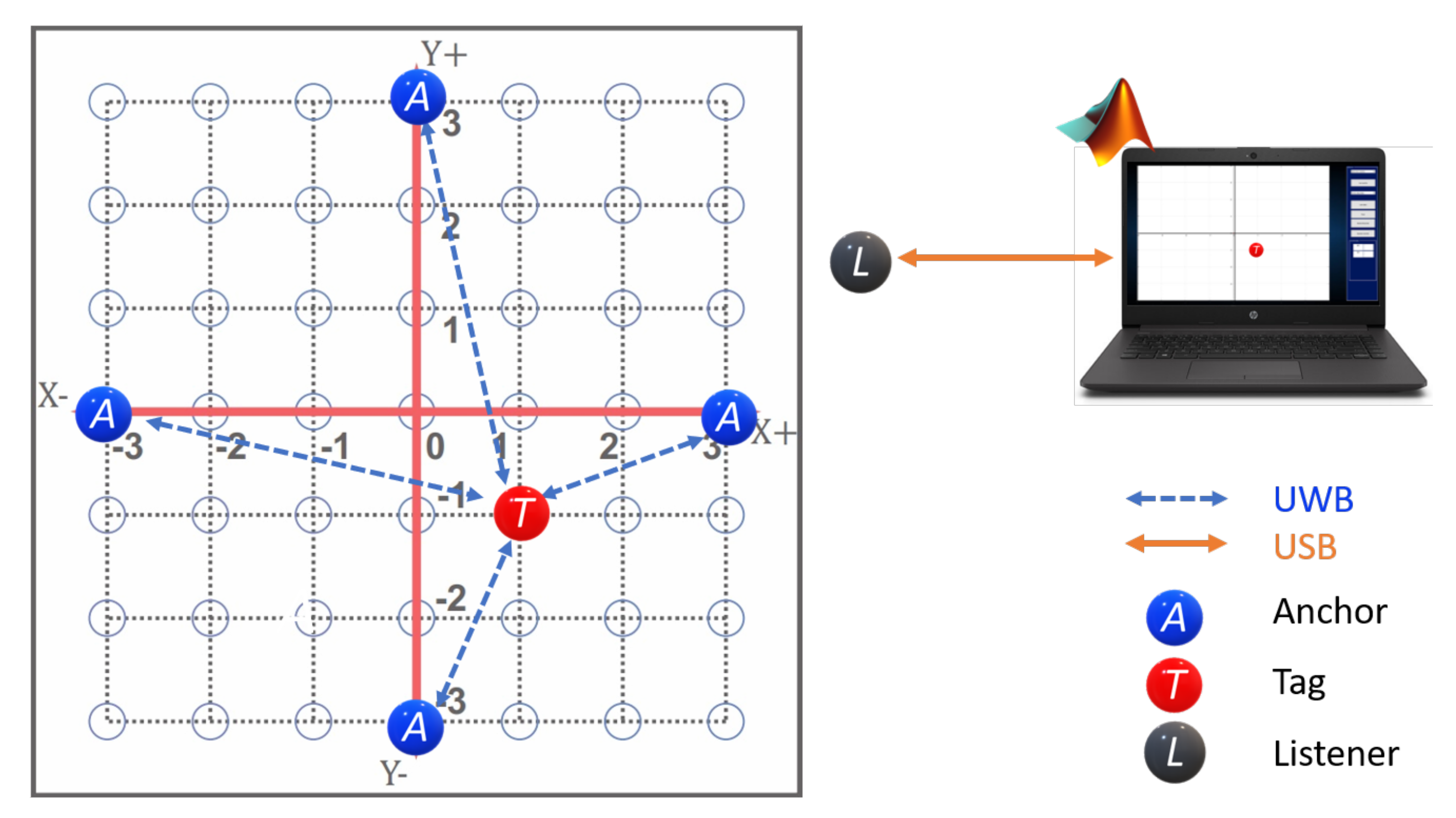
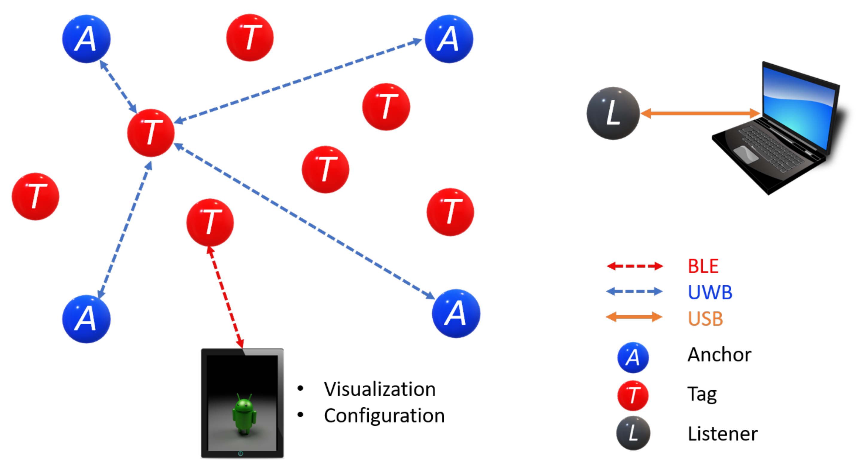
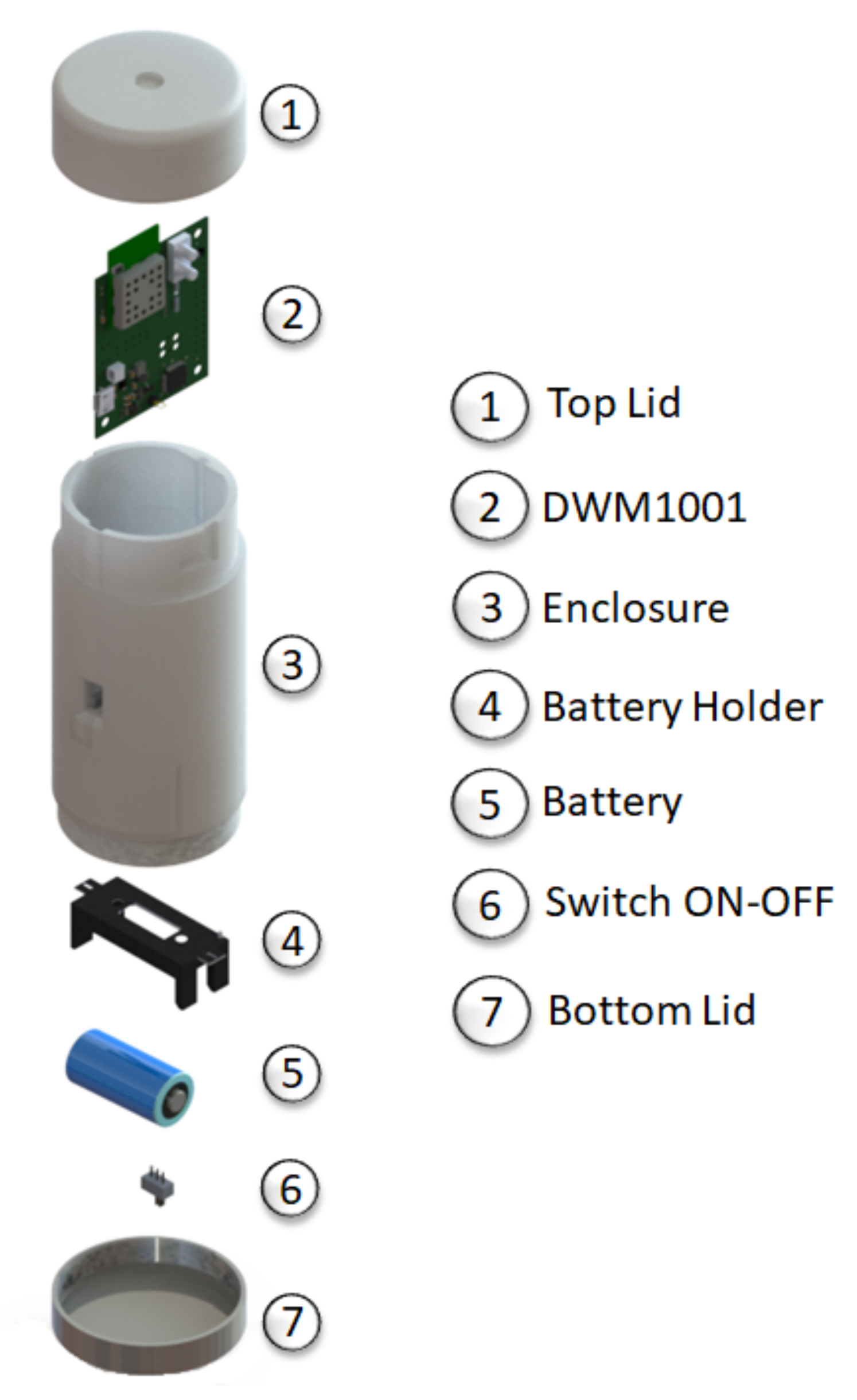
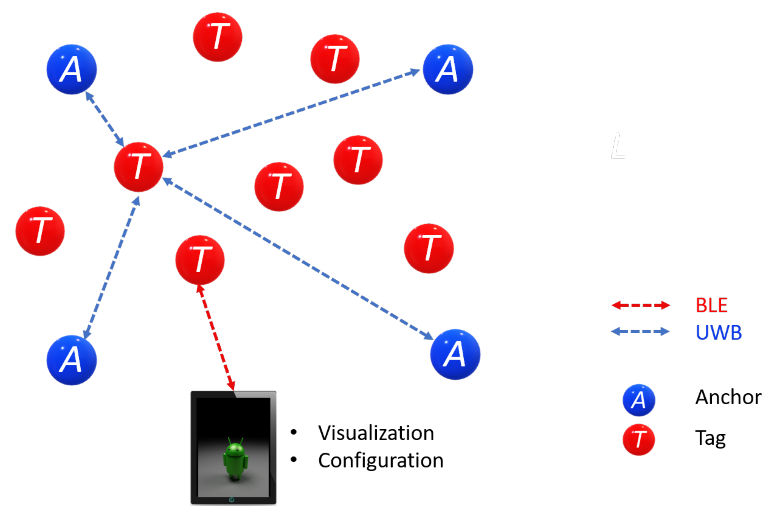
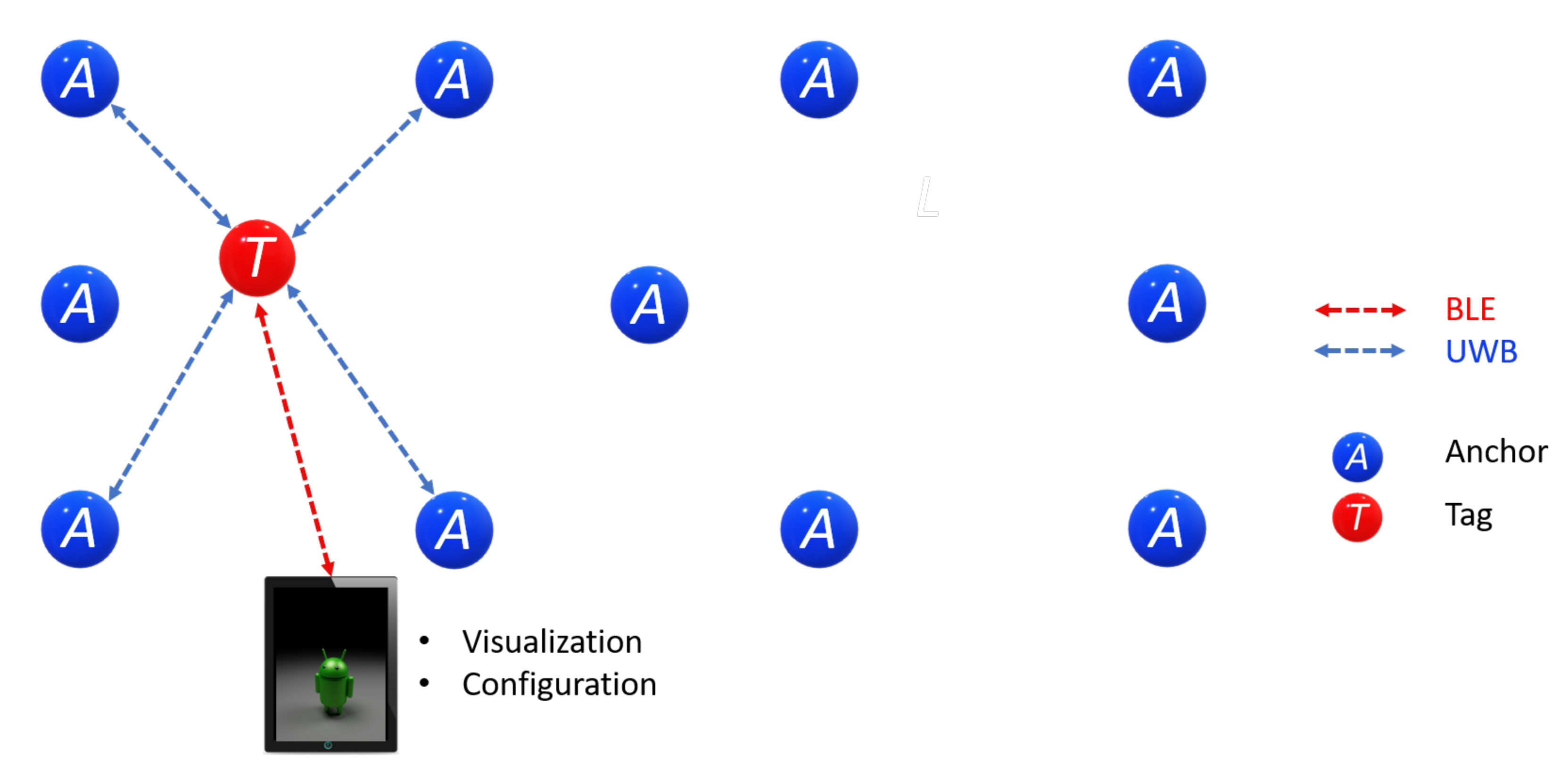
4.1. Anchor
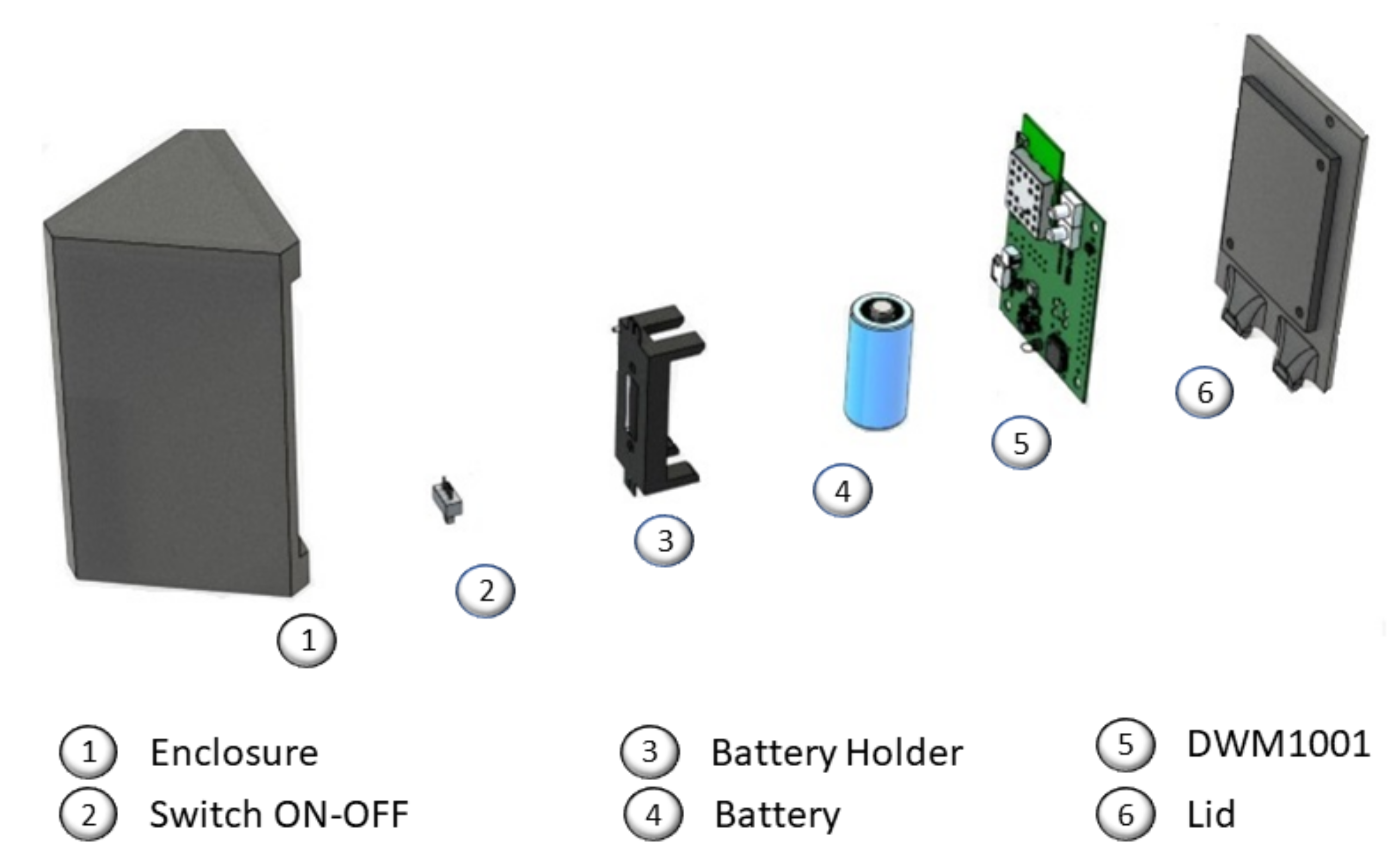
4.2. Tag
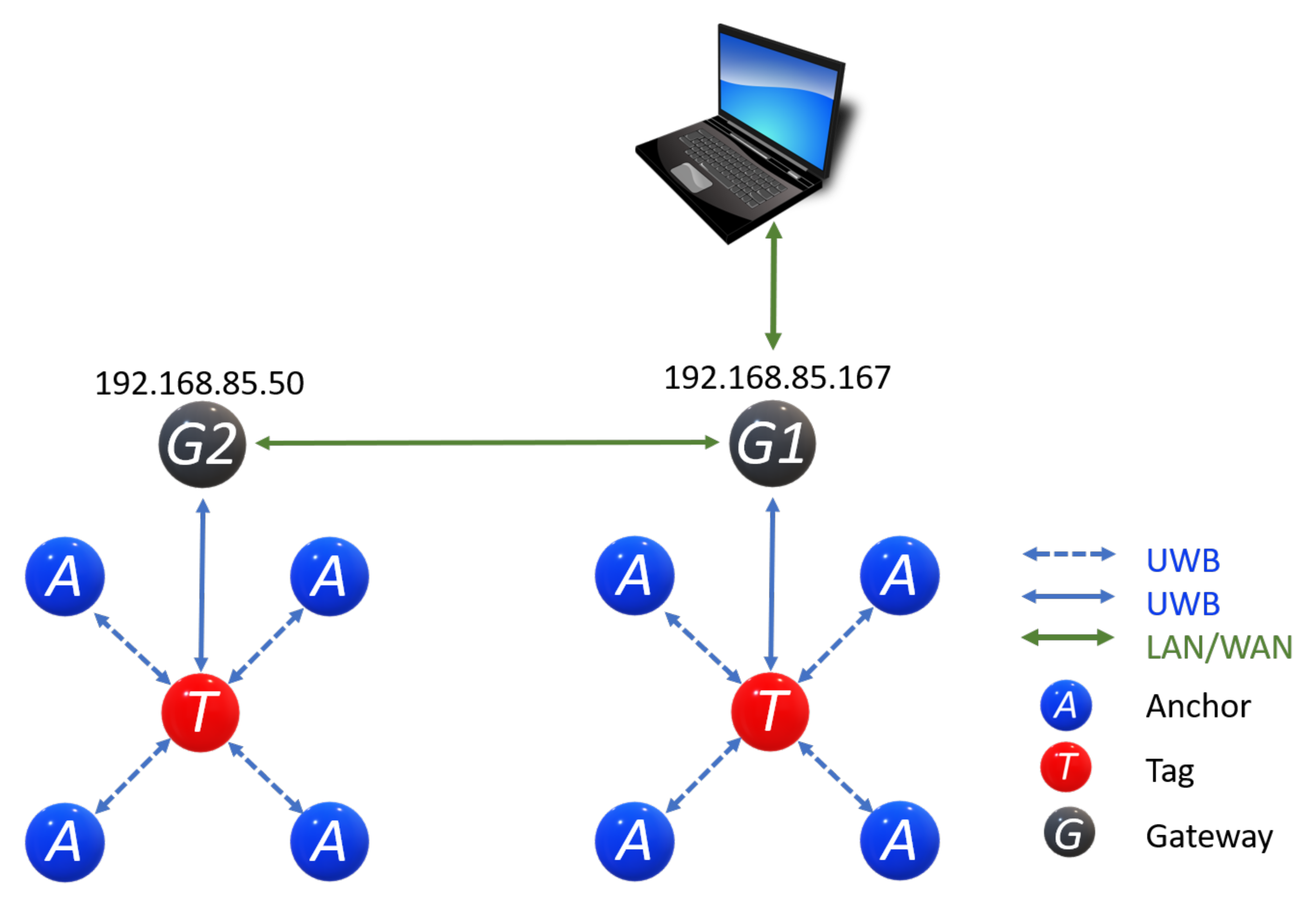
4.3. Listener
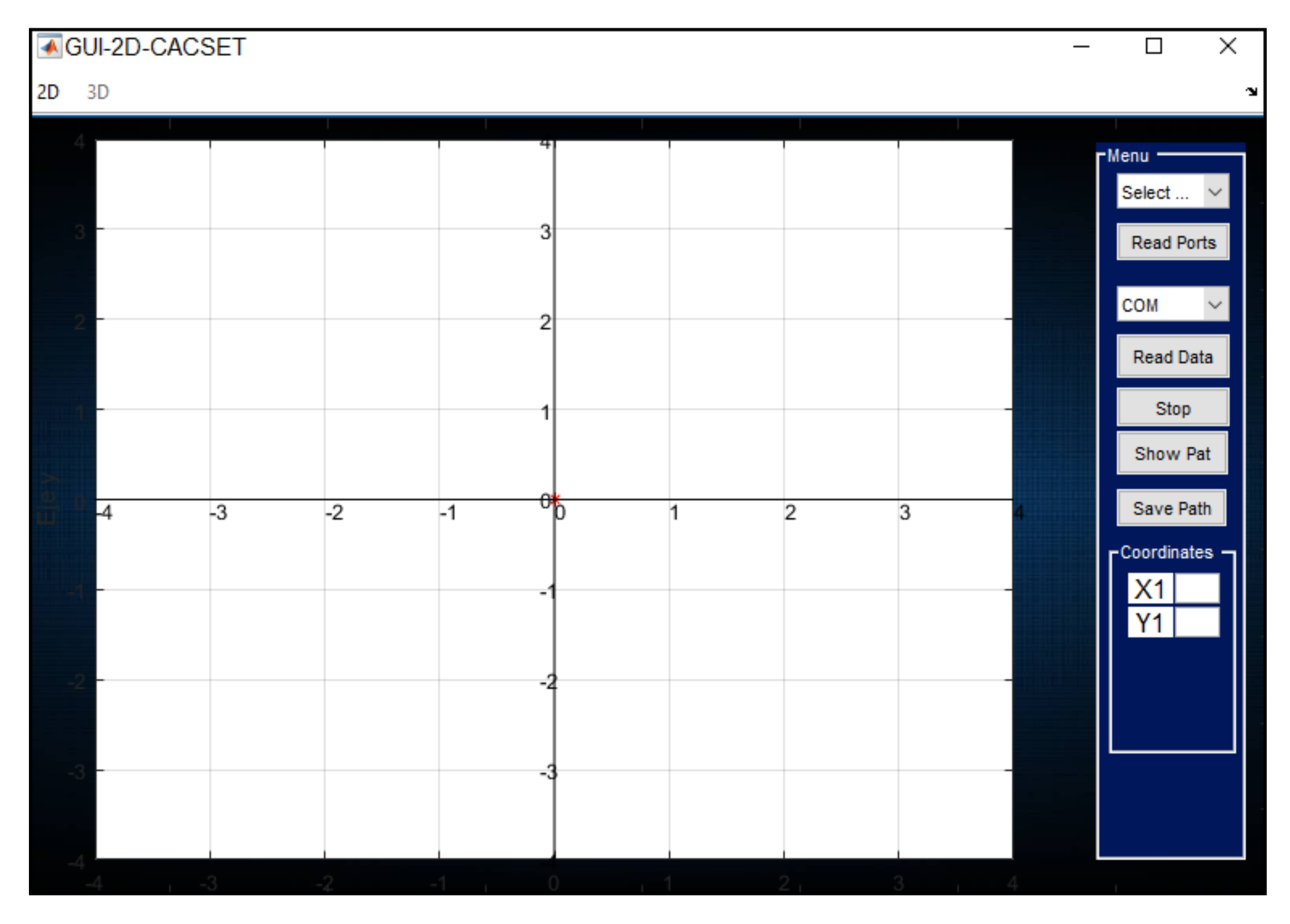
4.4. GUI-2D-CACSET
4.5. 2D-CACSET Board
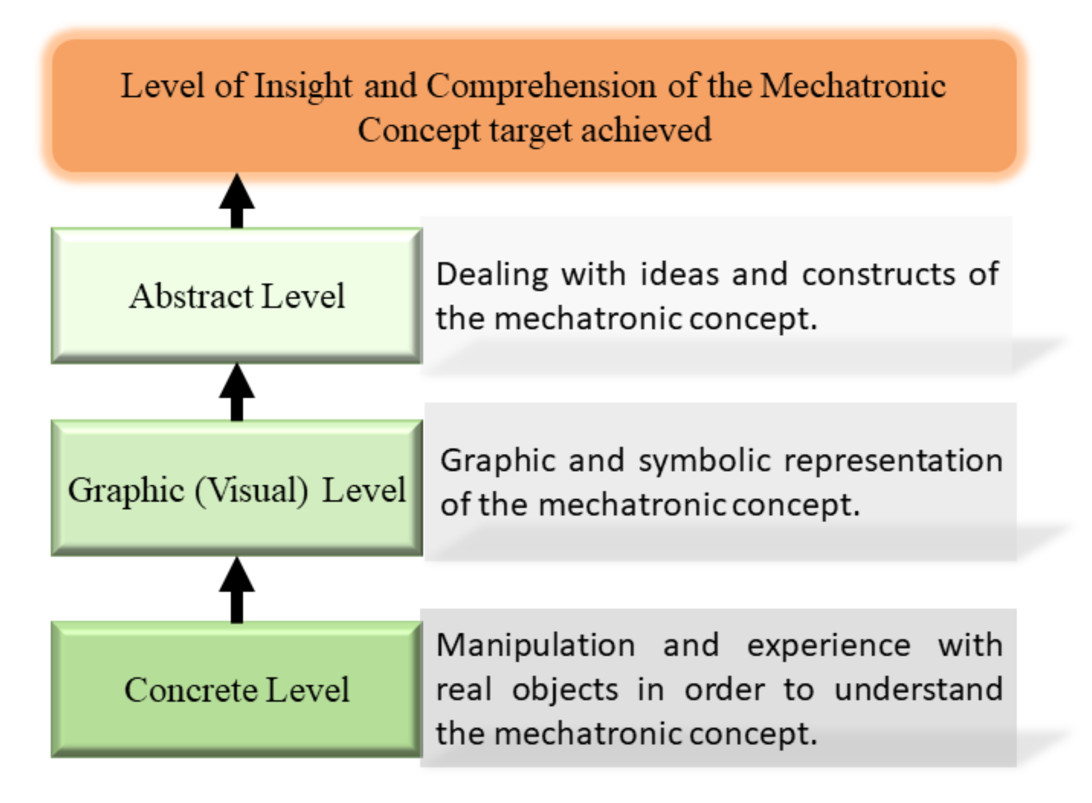
5. Instructional Design for Mechatronic Concept Two-Dimensional Cartesian Coordinates
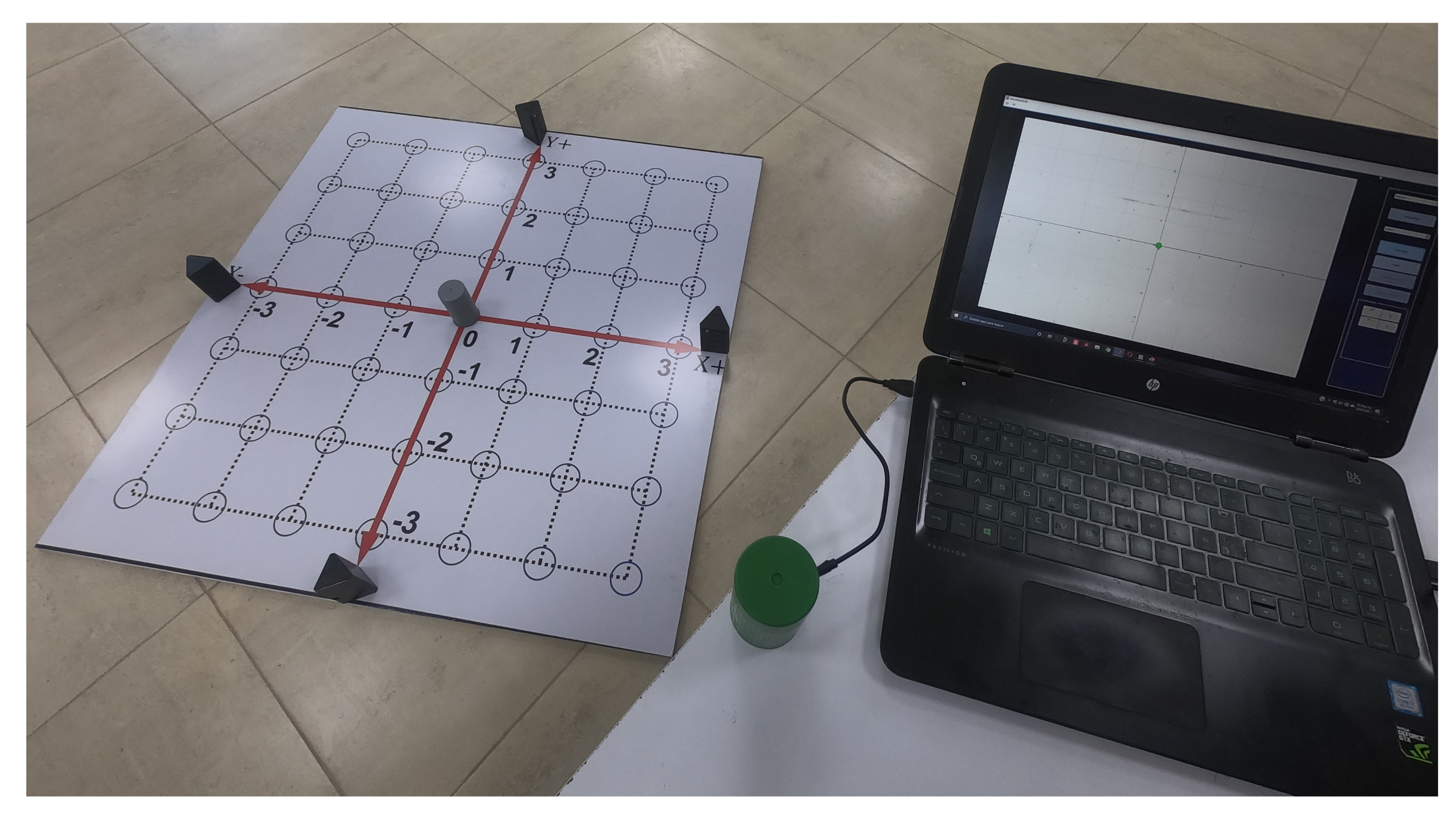
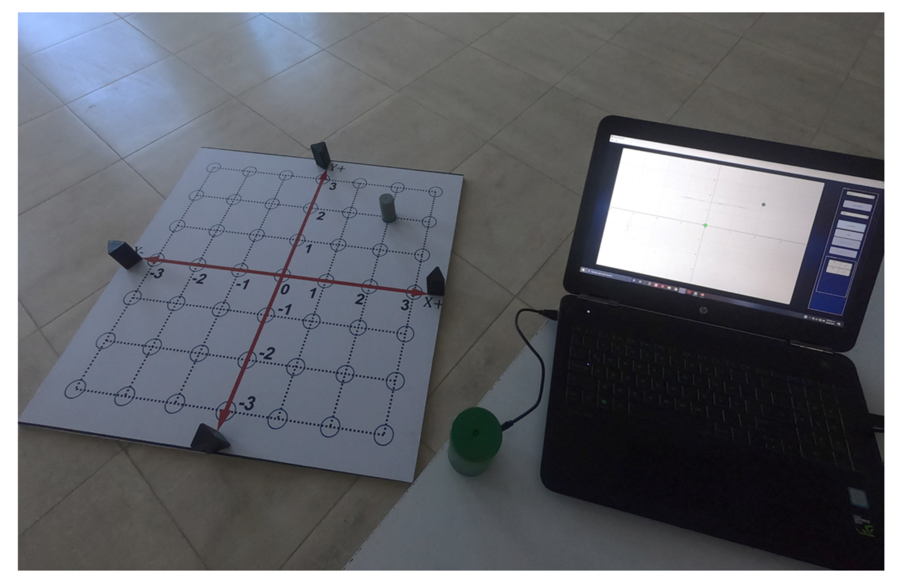
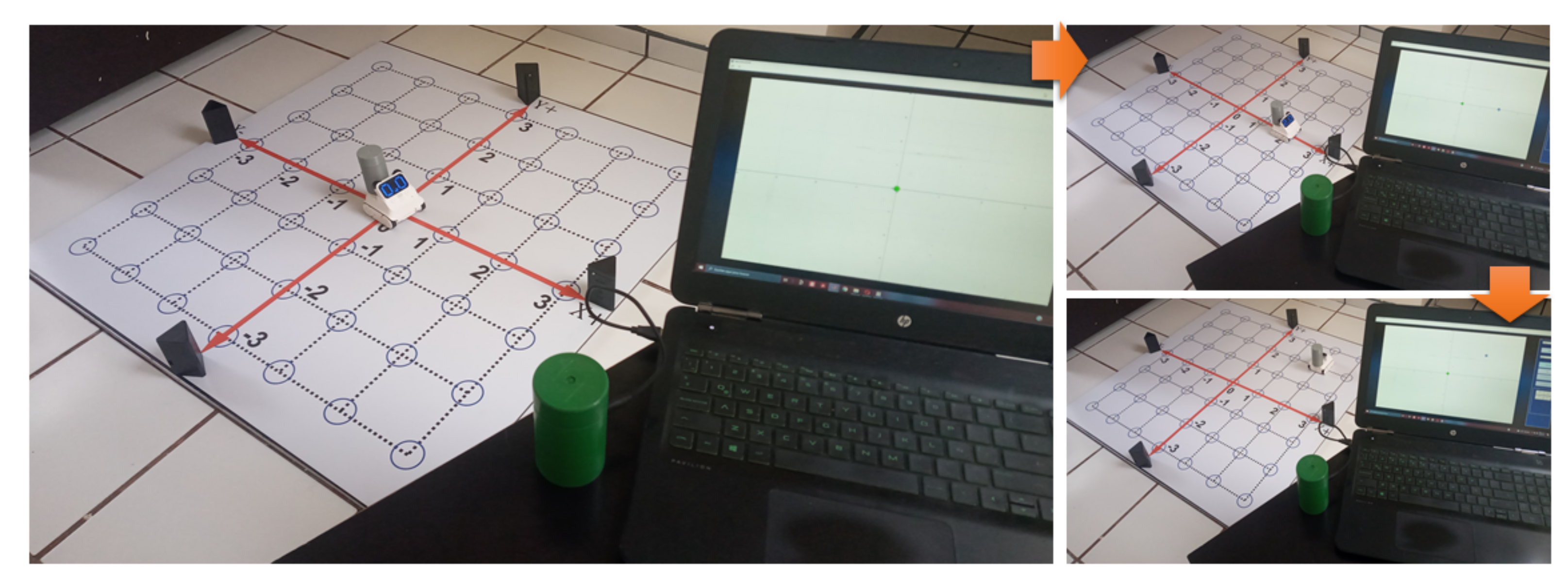
- Concrete Level: This level requires the student to experiment with real-world objects; therefore, the 2D-CACSET represents a way to achieve this. Here the students learn through interaction with artifacts, elements, and devices, depending on the context or discipline. In the spatial context, a bi-dimensional CCS is a widely used way to locate objects in mathematics. Therefore a Cartesian plane is the best choice to start with some basic spatial concepts. For this purpose, the 2D-CACSET board represents the Cartesian plane, and the Tag represents a point in the plane. The student can interact with the Cartesian plane making movements of the Tag; this is done by using colloquial language.
- Graphic Level: In this second level, the student must relate their skills acquired in the first level with symbolic elements. Software is a tool that can help at this level. The advantages of any software are that it is widely scalable, expandable, and can be used in a wide range of applications. Developing software also gives us the possibility to generate new capabilities in the future. For our purpose, the software will graphically show the elements that make up a two-dimensional plane and work in conjunction with the physical devices. Thus, an interaction between software and physical devices is done by using the GUI-2D-CACSET.
- Abstract Level: Abstract logical thinking is acquired at the stage of formal operations. Therefore, students can develop a mathematical understanding to enhance cognitive processes without relying on manipulating an object. For this purpose, the software for the graphic level can implement interactive practices, allowing students to strengthen their logical-mathematical intelligence and develop significant learning.
5.1. Practice 1: Cartesian Coordinate System
- Concrete Level:
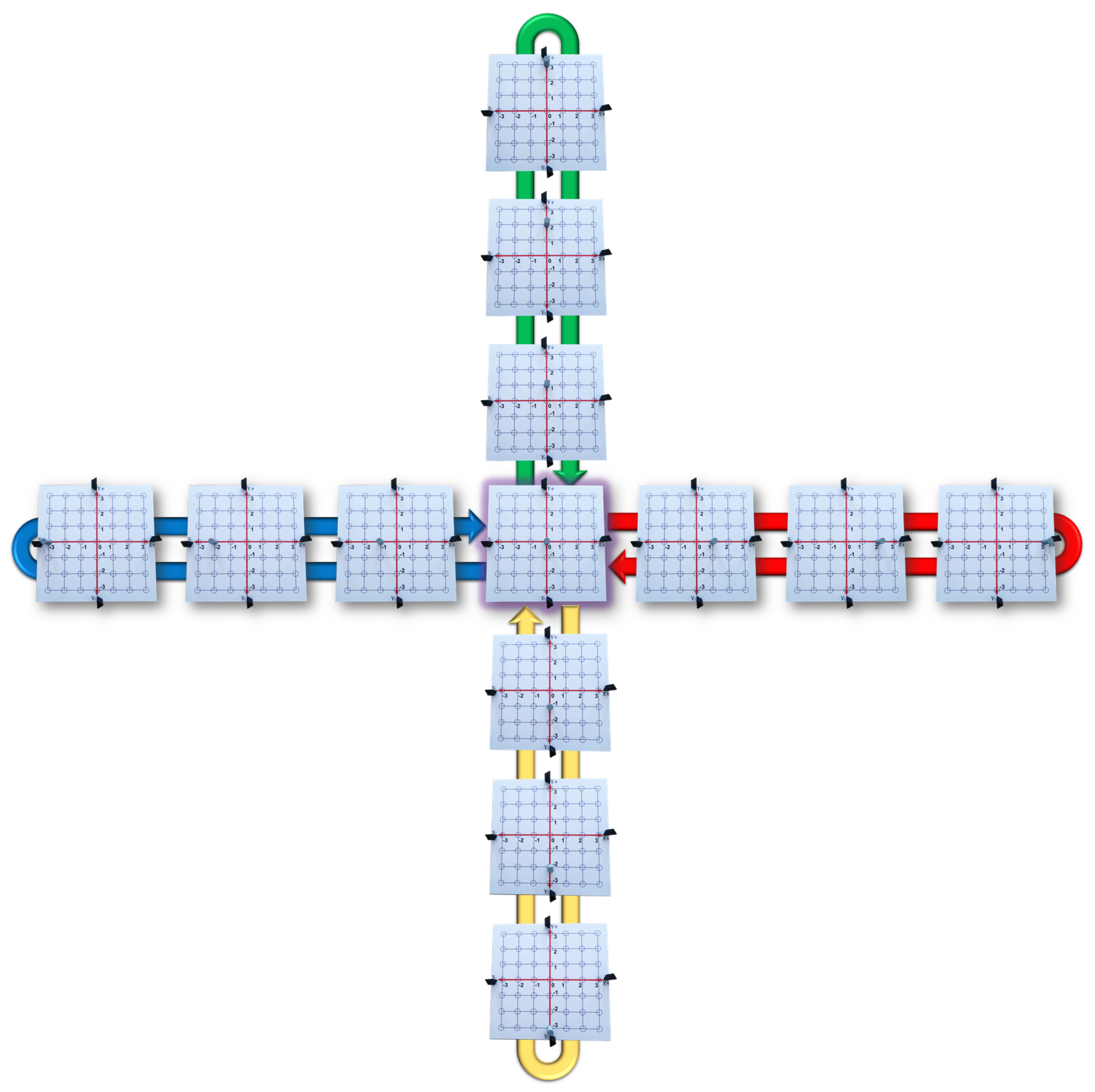
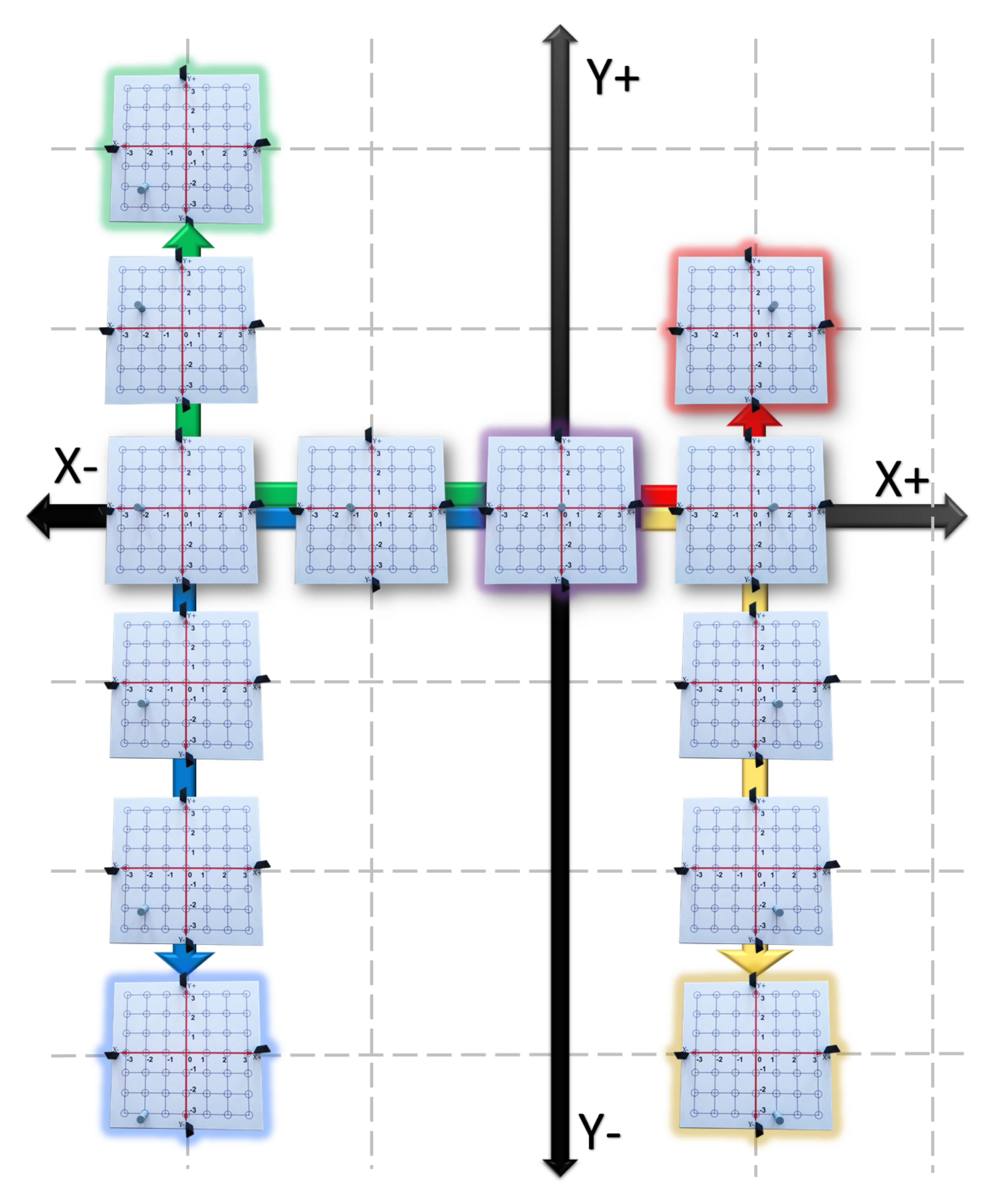
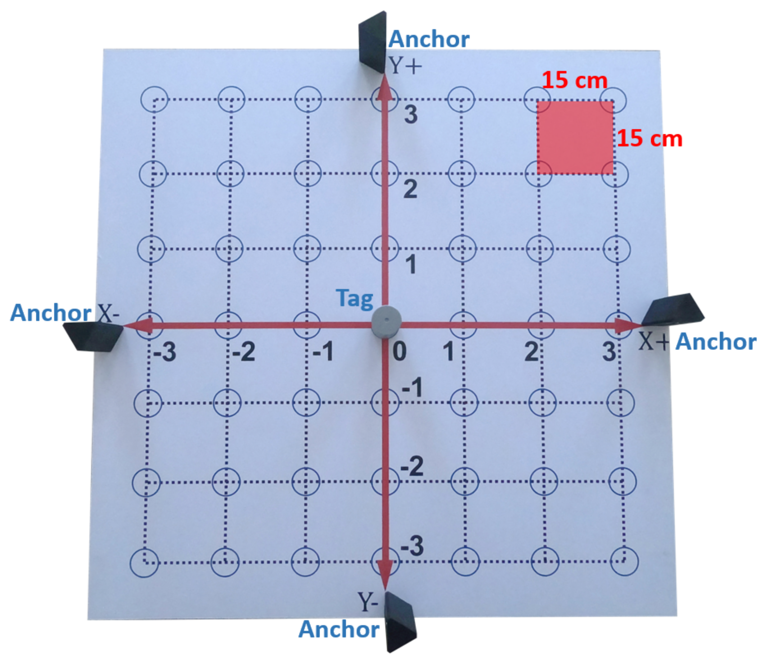
- Move the Tag from the origin to the rightward direction by jumping through each blue circle. Then, return to the origin moving the Tag leftward by jumping through each blue circle (see the red arrow in Figure 12).
- Move the Tag from the origin to the leftward direction by jumping through each blue circle. Then, return to the origin moving the Tag rightward by jumping through each blue circle (see the blue arrow in Figure 12).
- Move the Tag from the origin to the upward direction by jumping through each blue circle. Then, return to the origin moving the Tag downward by jumping through each blue circle (see the green arrow in Figure 12).
- Move the Tag from the origin to the downward direction by jumping through each blue circle. Then, return to the origin moving the Tag upward by jumping through each blue circle (see the yellow arrow in Figure 12).
- Graphic Level:
- 5.
- With a red marker repeat step 1 without separating the marker from the vinyl. Then, assign to this movement the symbol .
- 6.
- With a green marker repeat step 2 without separating the marker from the vinyl. Then, assign to this movement the symbol .
- 7.
- With a blue marker repeat step 3 without separating the marker from the vinyl. Then, assign to this movement the symbol .
- 8.
- With a yellow marker repeat step 4 without separating the marker from the vinyl. Then, assign to this movement the symbol . Finally, the student obtain a plus shaped draw.
- 9.
- Using the GUI-2D-CACSET and paying attention to the graphical interface repeat steps 1 to 4. Table 2 shows the collected data from the Tag representing the position value of x and y.
- Abstract Level:
- 10.
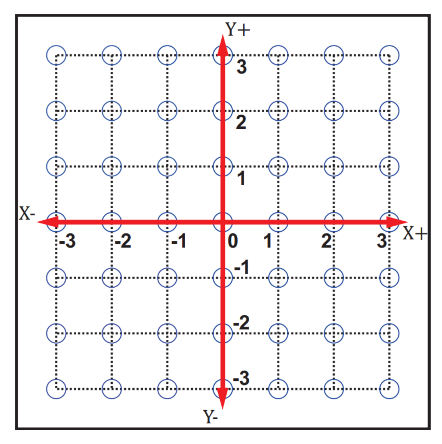
- The plus shape is the representation of the 2D CCS.
- 11.
- The horizontal line is know as a X axis. It encompasses a set of the real numbers .
- 12.
- The vertical line is know as a Y axis. It encompasses a set of the real numbers .
- 13.
- The intersection of the horizontal and vertical line is know as origin, and its representation in 2D coordinates is in which the first coordinate correspond tho the X axis and the second coordinate to the Y axis.
- 14.
- Finally, we can extend this knowledge to assign a pair of coordinate to any blue circle in the 2D-CACSET board to represent a point in the 2D CCS with coordinates.
5.2. Practice 2: Quadrants
- Concrete Level:
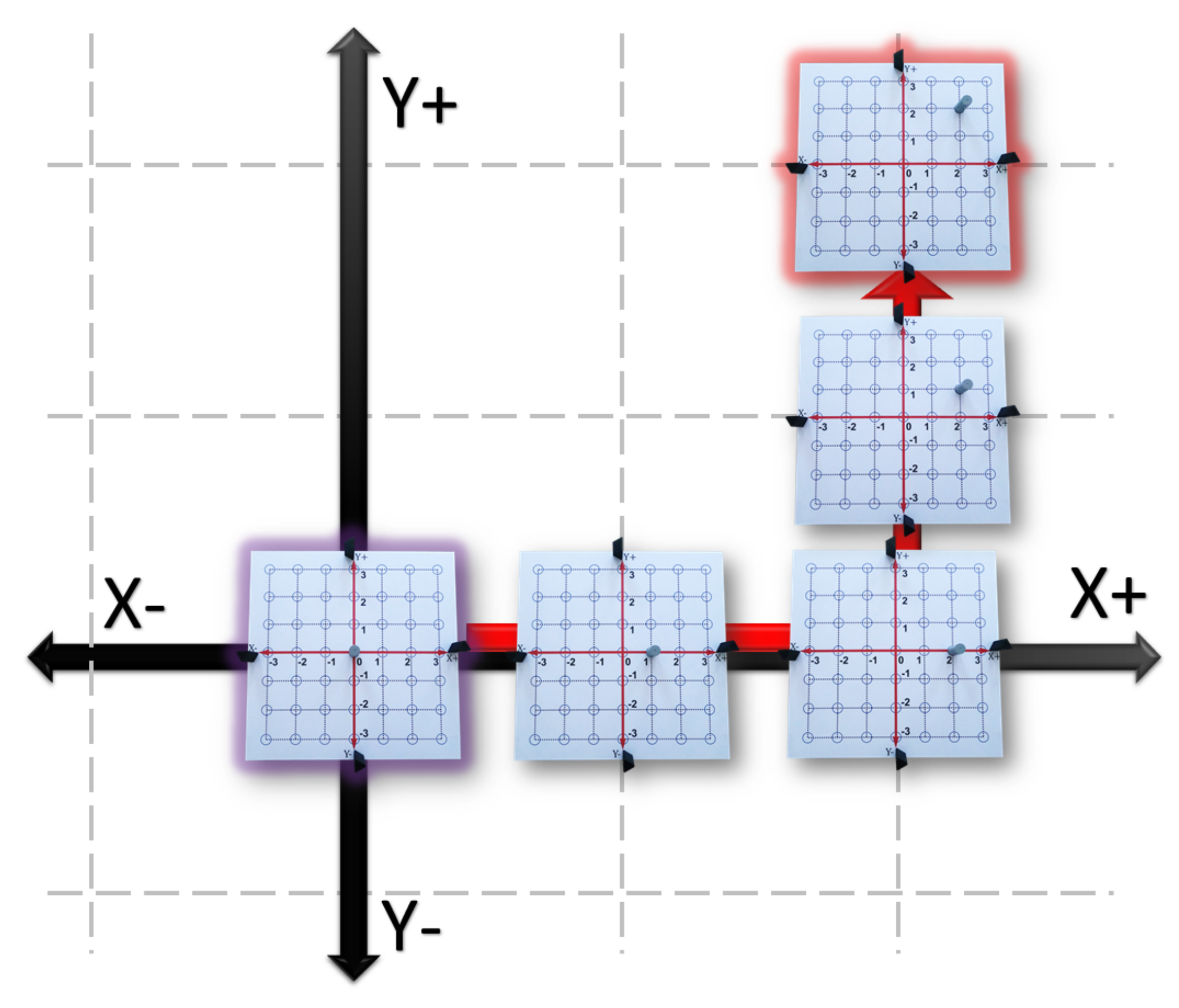
- Move the Tag from the origin to the rightward direction by jumping one blue circle. Then, to the upward direction by jumping one blue circle (see the red arrow in Figure 13).
- Move the Tag from the origin to the leftward direction by jumping two blue circles. Then, to the upward direction by jumping two blue circles (see the green arrow in Figure 13).
- Move the Tag from the origin to the leftward direction by jumping two blue circles. Then, to the downward direction by jumping three blue circles (see the blue arrow in Figure 13).
- Move the Tag from the origin to the rightward direction by jumping one blue circle. Then, to the downward direction by jumping three blue circles (see the yellow arrow in Figure 13).
- Graphic Level:
- 5.
- With a red marker repeat step 1 drawing a dotted line in the vinyl and fill in the blue circle you reached. Then, colors the area of the square bounded by the plus shaped that contain the circle. Then, assign to this area the Roman number I.
- 6.
- With a green marker repeat step 2 drawing a dotted line in the vinyl and fill in the blue circle you reached. Then, colors the area of the square bounded by the plus shaped that contain the circle. Then, assign to this area the Roman number II.
- 7.
- With a blue marker repeat step 3 drawing a dotted line in the vinyl and fill in the blue circle you reached. Then, colors the area of the square bounded by the plus shaped that contain the circle. Then, assign to this area the Roman number III.
- 8.
- With a yellow marker repeat step 4 drawing a dotted line in the vinyl and fill in the blue circle you reached. Then, colors the area of the square bounded by the plus shaped that contain the circle. Then, assign to this area the Roman number IV.
- 9.
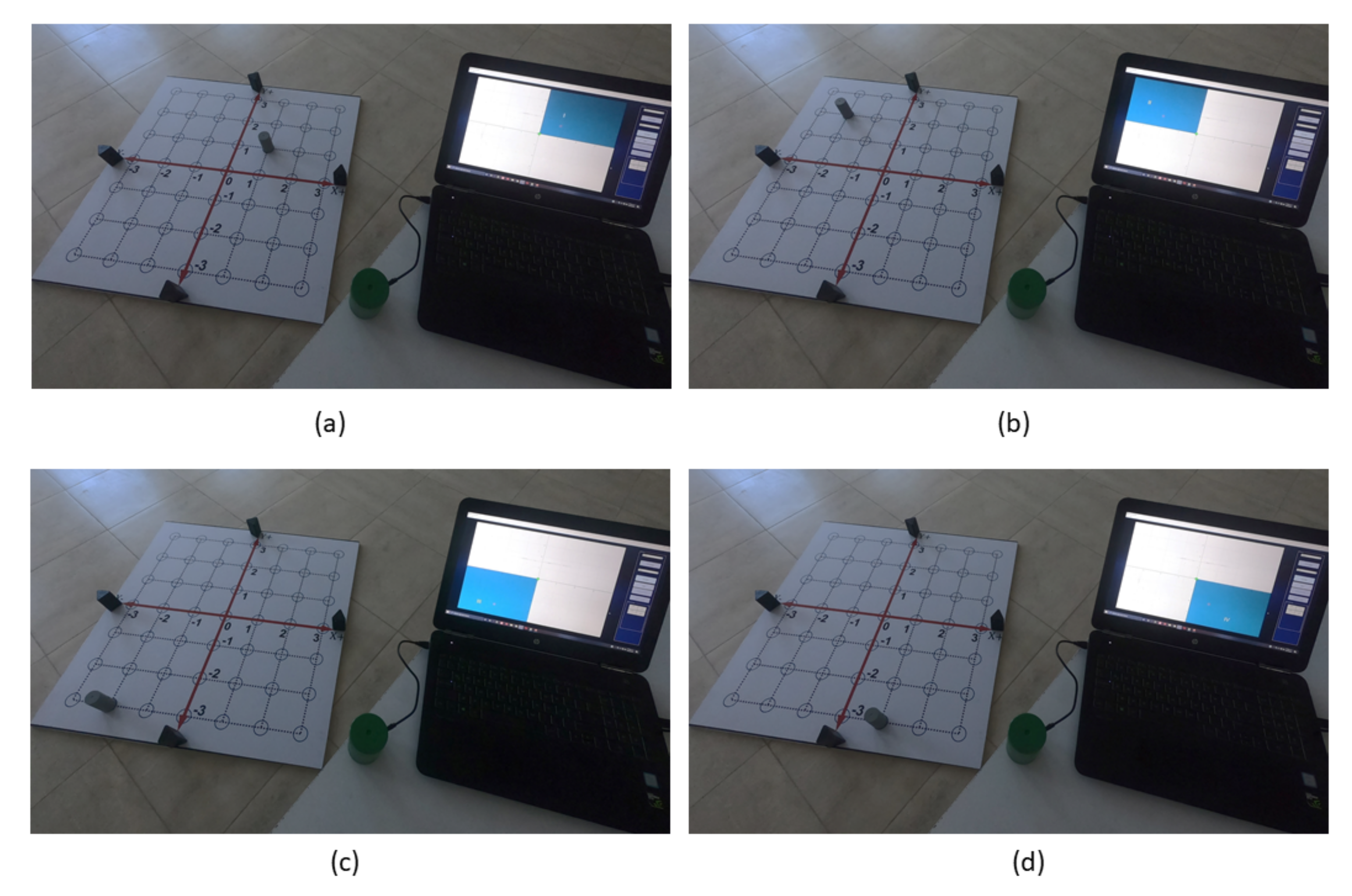
- Using the GUI-2D-CACSET and paying attention to the graphical interface repeat step 1 to 4 and verify that the illuminated area corresponds to the one that was colored. Table 3 shows the collected data from the Tag representing the position value of coordinates. In Figure 14 from (a) to (d) can be seen the Tag position in quadrants II, I, III, IV, respectively.
- Abstract Level:
- 10.
- The region labeled with the Roman number I correspond to the quadrant I of the 2D plane. The coordinates in this quadrant I are .
- 11.
- The region labeled with the Roman number II correspond to the quadrant I of the 2D plane. The coordinates in this quadrant II are .
- 12.
- The region labeled with the Roman number I correspond to the quadrant III of the 2D plane. The coordinates in this quadrant III are .
- 13.
- The region labeled with the Roman number I correspond to the quadrant IV of the 2D plane. The coordinates in this quadrant IV are .
5.3. Practice 3: Point in Cartesian Coordinate System
- Concrete Level:
- Move the Tag from the origin to the rightward direction by jumping two blue circles. Then, to the upward direction by jumping two blue circles (see the red arrow in Figure 15).
- Graphic Level:
- 2.
- With a red marker repeat step 1 drawing a dotted line in the vinyl and fill in the blue circle you reached. Then, assign the variable P to this circle.
- 3.
- Using the GUI-2D-CACSET and paying attention to the graphical interface repeat steps 1. Table 4 shows the collected data from the Tag representing the position value of coordinates.
- Abstract Level:
- 4.
- The circle you filled can be seen as very small, almost dimensionless. It is perceptible by a contrast of color or relief on a surface and is called a point. The coordinates of a point are two numbers, which are known as an ordered pair when written together. The ordered pair is written in parentheses, with the x (also called the abscissa) coordinate and the y (or ordinate) coordinate second. The coordinates of point P are . Finally, we can extend this knowledge to represent any point in the 2D CCS with coordinates.
6. Results
7. Discussion
Author Contributions
Funding
Institutional Review Board Statement
Informed Consent Statement
Data Availability Statement
Acknowledgments
Conflicts of Interest
Abbreviations
| 2D-CACSET | Two-Dimensional Cartesian Coordinate System Educational Toolkit |
| API | Application Programming Interface |
| ARM | Advanced RISC Machines |
| BLE | Bluetooth Low Energy |
| CAD | Computer Aided Design |
| CCS | Cartesian Coordinate System |
| COVID-19 | Coronavirus Disease 19 |
| CSV | Comma Separated Values |
| DRTLS | DWM Real-Time Location Systems |
| DWM | Decawave Module |
| EMCF | Educational Mechatronics Conceptual Framework |
| EMCF-LCM | EMCF Learning Construction Methodology |
| GPS | Global Positioning System |
| GUI | Graphical User Interface |
| IMU | inertial Measurement Unit |
| IR | Infrared |
| LAN | Local Area Network |
| LOS | Line-Of-Sight |
| PANS | Positioning and Networking Stack |
| RF | Radio Frequency |
| RFID | radio frequency identification |
| RSSI | Received Signal Strength Indicator |
| RTLS | Real-Time Location Systems |
| SoC | System on Chip |
| SPI | Serial Peripheral Interface |
| STEM | Science, Technology, Engineering and Mathematics |
| TDoA | Time Differential on Arrival |
| TWR | Two Way Ranging |
| UART | Universal Asynchronous Receiver-Transmitter |
| UWB | Ultra-Wide Band |
| VR | Virtual Reality |
| WAN | Wide Area Network |
| WiFi | Wireless Fidelity |
Appendix A
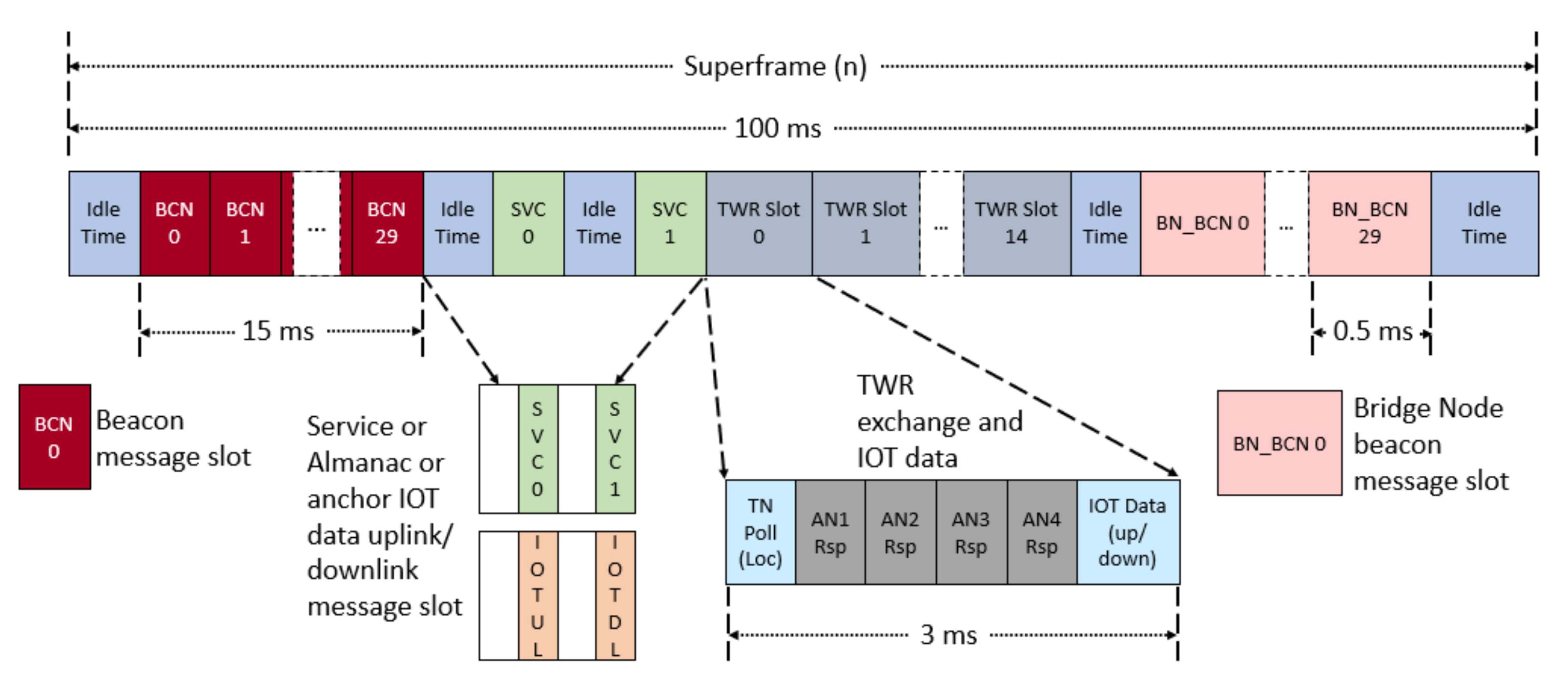
Appendix A.1. Decawave PANS Protocol for Location Solution

- Beacon slot: Each superframe starts with thirty Beacon Message slots (BCN), in which Anchors send beacon messages. This means that at most thirty active Anchors can operate in the same area.
- Service slot: Service slots are used for network service and almanacs messages (e.g., network join requests network).
- TWR slot: Two Way Ranging’s 15 slots are used for Tag-Anchor distance measurements, and for uploading/downloading additional data (e.g., IoT sensor data), each TWR slot lasts five milliseconds, in that interval, the Tag can calculate its distance with up to a maximum of 4 Anchors (AN1, AN2, AN3, AN4), It needs a minimum of three Anchors to calculate a location.
- Bridge node beacons slot: There are thirteen bridge node beacons that are used to indicate to Tags if there are any down-link data available for them.
- Idle Time slot: There is guard/idle time at the end of the superframe, which completes the superframe.
Appendix A.1.1. 2D CACSET Anchor Operation
Appendix A.1.2. 2D CACSET Tag Operation
Appendix A.1.3. 2D CACSET Listener Operation
References
- Álvarez-Marín, A.; Velázquez-Iturbide, J.Á.; Castillo-Vergara, M. Technology Acceptance of an Interactive Augmented Reality App on Resistive Circuits for Engineering Students. Electronics 2021, 10, 1286. [Google Scholar] [CrossRef]
- Haramaki, T.; Nishino, H. An Engineering Education Support System Using Projection-Based AR. In Proceedings of the 2016 19th International Conference on Network-Based Information Systems (NBiS), Ostrava, Czech Republic, 7–9 September 2016; pp. 267–272. [Google Scholar] [CrossRef]
- Guerrero-Osuna, H.A.; Luque-Vega, L.F.; Carlos-Mancilla, M.A.; Ornelas-Vargas, G.; Castañeda-Miranda, V.H.; Carrasco-Navarro, R. Implementation of a MEIoT Weather Station with Exogenous Disturbance Input. Sensors 2021, 21, 1653. [Google Scholar] [CrossRef] [PubMed]
- Behzadan, A.; Kamat, R. A framework for utilizing context-aware augmented reality visualization IN ENGINEERING education. In Proceedings of the 12th International Conference on Construction Application of Virtual Reality, Taipei, Taiwan, 1–2 November 2012. [Google Scholar]
- Liu, M.C.; Lai, C.H.; Su, Y.N.; Huang, S.H.; Chien, Y.C. Learning with Great Care: The Adoption of the Multi-sensor Technology in Education. In Sensing Technology: Current Status and Future Trends III; Mason, A., Mukhopadhyay, S., Jayasundera, K., Eds.; Springer: Berlin/Heidelberg, Germany, 2015; pp. 223–242. [Google Scholar] [CrossRef]
- Gendreau Chakarov, A.; Recker, M.; Jacobs, J.; Van Horne, K.; Sumner, T. Designing a Middle School Science Curriculum that Integrates Computational Thinking and Sensor Technology. In Proceedings of the 50th ACM Technical Symposium on Computer Science Education (SIGCSE ’19), Minneapolis, MN, USA, 27 February–2 March 2019; Association for Computing Machinery: New York, NY, USA, 2019; pp. 818–824. [Google Scholar] [CrossRef]
- Du, J.; Nan, Z. Research on the intelligent model of progress in physical education training based on motion sensor. Microprocess. Microsyst. 2021, 82, 103903. [Google Scholar] [CrossRef]
- Clark, J.; Falkner, W.; Balaji Kuruvadi, S.; Bruce, D.; Zummo, W.; Yelamarthi, K. Development and Implementation of Real-Time Wireless Sensor Networks for Data Literacy Education. In Proceedings of the 2019 ASEE North Central Section Conference, Morgan Town, WV, USA, 22–23 March 2019; American Society for Engineering Education: Harrison, MI, USA, 2019. [Google Scholar]
- Martinez-Maldonado, R.; Yan, L.; Deppeler, J.; Phillips, M.; Gašević, D. Classroom Analytics: Telling Stories about Learning Spaces using Sensor Data. In Hybrid Learning Spaces; Gil, E., Mor, Y., Dimitriadis, Y., Köppe, C., Eds.; Springer: Cham, Switzerland, 2021. [Google Scholar]
- Fjukstad, B.; Angelvik, N.; Wulff Hauglann, M.; Sveia Knutsen, J.; Grønnesby, M.; Gunhildrud, H.; Ailo Bongo, L. Low-Cost Programmable Air Quality Sensor Kits in Science Education. In Proceedings of the 49th ACM Technical Symposium on Computer Science Education (SIGCSE ’18), Baltimore, MD, USA, 21–24 February 2018; Association for Computing Machinery: New York, NY, USA, 2018; pp. 227–232. [Google Scholar] [CrossRef]
- Carlos-Mancilla, M.A.; Luque-Vega, L.F.; Guerrero-Osuna, H.A.; Ornelas-Vargas, G.; Aguilar-Molina, Y.; González-Jiménez, L.E. Educational Mechatronics and Internet of Things: A Case Study on Dynamic Systems Using MEIoT Weather Station. Sensors 2021, 21, 181. [Google Scholar] [CrossRef] [PubMed]
- Eickholt, J.; Johnson, M.R.; Seeling, P. Practical Active Learning Stations to Transform Existing Learning Environments Into Flexible, Active Learning Classrooms. IEEE Trans. Educ. 2021, 64, 95–102. [Google Scholar] [CrossRef]
- Setiawati, H.; Juniati, D.; Khabibah, S. Student’s Geometric Thinking in Understanding Volume with Three-Dimensional Images of Cubes and Nets. J. Phys. Conf. Ser. 2019, 1417, 012053. [Google Scholar] [CrossRef]
- Battista, M.T.; Clements, D.H. Students’ Understanding of Three-Dimensional Rectangular Arrays of Cubes. J. Res. Math. Educ. 1996, 27, 258–292. [Google Scholar] [CrossRef]
- O’Connor, E. Virtual Reality: Bringing Education to Life. In Games and Simulations in Teacher Education; Bradley, E., Ed.; Springer International Publishing: Cham, Swizerland, 2020; pp. 155–167. ISBN 9783030445263. [Google Scholar]
- Wright, W.G. Using virtual reality to augment perception, enhance sensorimotor adaptation, and change our minds. Front. Syst. Neurosci. 2014, 8, 56. [Google Scholar] [CrossRef] [PubMed] [Green Version]
- Volkwyn, T.S.; Gregorcic, B.; Airey, J.; Linder, C. Learning to use Cartesian coordinate systems to solve physics problems: The case of ‘movability’. Eur. J. Phys. 2020, 41, 4. [Google Scholar] [CrossRef]
- Langer, K.; Lietze, S.; Krizek, G.C. Vector AR3-APP—A Good-Practice Example of Learning with Augmented Reality. Eur. J. Open Distance E-Learn. 2020, 23, 51–64. [Google Scholar] [CrossRef]
- Yepes, I.; Couto-Barone, D.A.; Duarte-Porciuncula, C.M. Use of Drones as Pedagogical Technology in STEM Disciplines. Informatics in Education 2021. Available online: https://0-doi-org.brum.beds.ac.uk/10.15388/infedu.2022.08 (accessed on 17 September 2021).
- Montiel, M.; Vidakovic, D.; Kabael, T. Relationship between Students’ Understanding of Functions in Cartesian and Polar Coordinate Systems. Investig. Math. Learn. 2008, 1, 52–70. [Google Scholar] [CrossRef]
- Uttal, D.H.; Cohen, C.A. Spatial thinking and STEM education: When, why, and how? In Psychology of Learning and Motivation; Elsevier: Amsterdam, The Netherlands, 2012; Volume 57, pp. 147–181. [Google Scholar] [CrossRef]
- Newcombe, N. Harnessing Spatial Thinking to Support Stem Learning; OECD Education Working Papers; Organisation for Economic Co-Operation and Development (OECD): Paris, France, 2017. [Google Scholar] [CrossRef]
- Luque-Vega, L.F.; Lopez-Neri, E.; Santoyo, A.; Ruiz-Duarte, J.; Farrera-Vazquez, N. Educational Methodology Based on Active Learning for Mechatronics Engineering Students: Towards Educational Mechatronics. Comput. Sist. 2019, 23, 325–333. [Google Scholar] [CrossRef]
- Miranda-Flores, J.R.; Luque-Vega, L.F.; López-Neri, E.; González-Jiménez, L.E.; Saad, M. Design and implementation of a novel robot manipulator kit for industry 4.0 through educational mechatronics. In Proceedings of the 22nd International Conference on Engineering and Product Design Education, Herning, Denmark, 10–11 September 2020. [Google Scholar] [CrossRef]
- Baharin, N.; Kamarudin, N.; Manaf, U.K.A. Integrating STEM Education Approach in Enhancing Higher Order Thinking Skills. Int. J. Acad. Res. Bus. Soc. Sci. 2018, 8, 810–821. [Google Scholar] [CrossRef]
- Rozi, A.; Khoiri, A.; Farida, R.D.M.; Sunarsi, D.; Iswadi, U. The Fullness of Higher Order Thinking Skills (HOTs) in Applied Science Textbooks of Vocational Schools. J. Phys. Conf. Ser. 2021, 1764, 012143. [Google Scholar] [CrossRef]
- Oguntala, G.; Abd-Alhameed, R.; Jones, S.; Noras, J.; Patwary, M.; Rodriguez, J. Indoor Location Identification Technologies for Real-Time IoT-Based Applications: An Inclusive Survey; Computer Science Review: Amsterdam, The Netherlands, 2018; Volume 30, pp. 55–79. [Google Scholar] [CrossRef]
- Alarifi, A.; Al-Salman, A.; Alsaleh, M.; Alnafessah, A.; Al-Hadhrami, S.; Al-Ammar, M.A.; Al-Khalifa, H.S. Ultra Wideband Indoor Positioning Technologies: Analysis and Recent Advances. Sensors 2016, 16, 707. [Google Scholar] [CrossRef] [PubMed]
- Aybakan, T.; Kerestecioğlu, F. Indoor Positioning Using Federated Kalman Filter. In Proceedings of the 2018 3rd International Conference on Computer Science and Engineering (UBMK), Antaly, Turkey, 20–23 September 2018; pp. 483–488. [Google Scholar] [CrossRef]
- Syafrudin, M.; Lee, K.; Alfian, G.; Lee, J.; Rhee, J. Application of Bluetooth Low Energy-Based Real-Time Location System for Indoor Environments. In Proceedings of the 2018 2nd International Conference on Big Data and Internet of Things (BDIOT 2018), Beijing, China, 24–26 October 2018; Association for Computing Machinery: New York, NY, USA, 2018; pp. 167–171. [Google Scholar] [CrossRef]
- Baqai, A.; Talpur, A.; Umrani, F.A. Design, Implementation and Evaluation of IR-Based Tagging System for RTLS. Wirel. Pers. Commun. 2020, 113, 1345–1358. [Google Scholar] [CrossRef]
- Zou, H.; Chen, Z.; Jiang, H.; Xie, L.; Spanos, C. Accurate indoor localization and tracking using mobile phone inertial sensors, WiFi and iBeacon. In Proceedings of the 2017 IEEE International Symposium on Inertial Sensors and Systems (INERTIAL), Kauai, HI, USA, 28–30 March 2017; pp. 1–4. [Google Scholar] [CrossRef]
- Ou, C.; Chao, C.; Chang, F.; Wang, S.; Liu, G.; Wu, M.; Cho, K.; Hwang, L.; Huan, Y. A ZigBee position technique for indoor localization based on proximity learning. In Proceedings of the 2017 IEEE International Conference on Mechatronics and Automation (ICMA), Kagawa, Japan, 6–9 August 2017; pp. 875–880. [Google Scholar] [CrossRef]
- Švecová, M.; Kocur, D.; Švingál, M. UWB-PerLoc-MAT: MATLAB App for Person Localization by UWB Sensor. In Proceedings of the 2018 16th International Conference on Emerging eLearning Technologies and Applications (ICETA), Stary Smokovec, Slovakia, 15–16 November 2018; pp. 545–550. [Google Scholar] [CrossRef]
- Lee, J.S.; Su, Y.W.; Shen, C.C. A comparative study of wireless protocols: Bluetooth, UWB, ZigBee, and Wi-Fi. In Proceedings of the IECON Proceedings (Industrial Electronics Conference), Taipei, Taiwan, 5–8 November 2007; pp. 46–51. [Google Scholar] [CrossRef] [Green Version]
- Decawave Ltd. The DWM1001 module based on Decawave’s DW1000 Ultra Wideband (UWB) transceiver IC. In DWM1001-DEV Datasheet; Available online: https://www.decawave.com/wp-content/uploads/2021/01/DWM1001C_Datasheet.pdf (accessed on 17 September 2021).
- Van Herbruggen, B.; Jooris, B.; Rossey, J.; Ridolfi, M.; Macoir, N.; Van den Brande, Q.; Lemey, S.; De Poorter, E. Wi-PoS: A Low-Cost, Open Source Ultra-Wideband (UWB) Hardware Platform with Long Range Sub-GHz Backbone. Sensors 2019, 19, 1548. [Google Scholar] [CrossRef] [PubMed] [Green Version]
- Plan de Estudios de Ingeniería en Mecatrónica UVM. Available online: https://uvm.mx/storage/app/uploads/public/5ff/78f/182/5ff78f1826faa883127299.pdf?trackid=goosrcarpaonlstmecgen (accessed on 14 September 2021).
- Steup, C.; Beckhaus, J.; Mostaghim, S. A Single-Copter UWB-Ranging-Based Localization System Extendable to a Swarm of Drones. Drones 2021, 5, 85. [Google Scholar] [CrossRef]
- Dhankhar, A.; Solanki, K. State of the Art of Learning Analytics in Higher Education. Int. J. Emerg. Trends Eng. Res. 2020, 8, 3. [Google Scholar] [CrossRef]
- Jiménez, A.R.; Seco, F. Improving the Accuracy of Decawave’s UWB MDEK1001 Location System by Gaining Access to Multiple Ranges. Sensors 2021, 21, 1787. [Google Scholar] [CrossRef] [PubMed]


| Anchor Name | Position () in cm |
|---|---|
| Value | Value | Value | Value | Value | Value | Value | Value |
|---|---|---|---|---|---|---|---|
| 0 | 0 | 0 | 0 | 0 | 0 | 0 | 0 |
| 1 | 0 | 0 | 0 | 1 | 0 | ||
| 2 | 0 | 0 | 0 | 2 | 0 | ||
| 3 | 0 | 0 | 0 | 3 | 0 | ||
| 2 | 0 | 0 | 0 | 2 | 0 | ||
| 1 | 0 | 0 | 0 | 1 | 0 | ||
| 0 | 0 | 0 | 0 | 0 | 0 | 0 | 0 |
| Quadrant 1 | Quadrant 2 | Quadrant 3 | Quadrant 4 |
|---|---|---|---|
| − | |||
| − | |||
| − | − | − |
Publisher’s Note: MDPI stays neutral with regard to jurisdictional claims in published maps and institutional affiliations. |
© 2021 by the authors. Licensee MDPI, Basel, Switzerland. This article is an open access article distributed under the terms and conditions of the Creative Commons Attribution (CC BY) license (https://creativecommons.org/licenses/by/4.0/).
Share and Cite
Castañeda-Miranda, V.H.; Luque-Vega, L.F.; Lopez-Neri, E.; Nava-Pintor, J.A.; Guerrero-Osuna, H.A.; Ornelas-Vargas, G. Two-Dimensional Cartesian Coordinate System Educational Toolkit: 2D-CACSET. Sensors 2021, 21, 6304. https://0-doi-org.brum.beds.ac.uk/10.3390/s21186304
Castañeda-Miranda VH, Luque-Vega LF, Lopez-Neri E, Nava-Pintor JA, Guerrero-Osuna HA, Ornelas-Vargas G. Two-Dimensional Cartesian Coordinate System Educational Toolkit: 2D-CACSET. Sensors. 2021; 21(18):6304. https://0-doi-org.brum.beds.ac.uk/10.3390/s21186304
Chicago/Turabian StyleCastañeda-Miranda, Víctor H., Luis F. Luque-Vega, Emmanuel Lopez-Neri, Jesús Antonio Nava-Pintor, Héctor A. Guerrero-Osuna, and Gerardo Ornelas-Vargas. 2021. "Two-Dimensional Cartesian Coordinate System Educational Toolkit: 2D-CACSET" Sensors 21, no. 18: 6304. https://0-doi-org.brum.beds.ac.uk/10.3390/s21186304