Development of a Real-Time Human-Robot Collaborative System Based on 1 kHz Visual Feedback Control and Its Application to a Peg-in-Hole Task †

Abstract
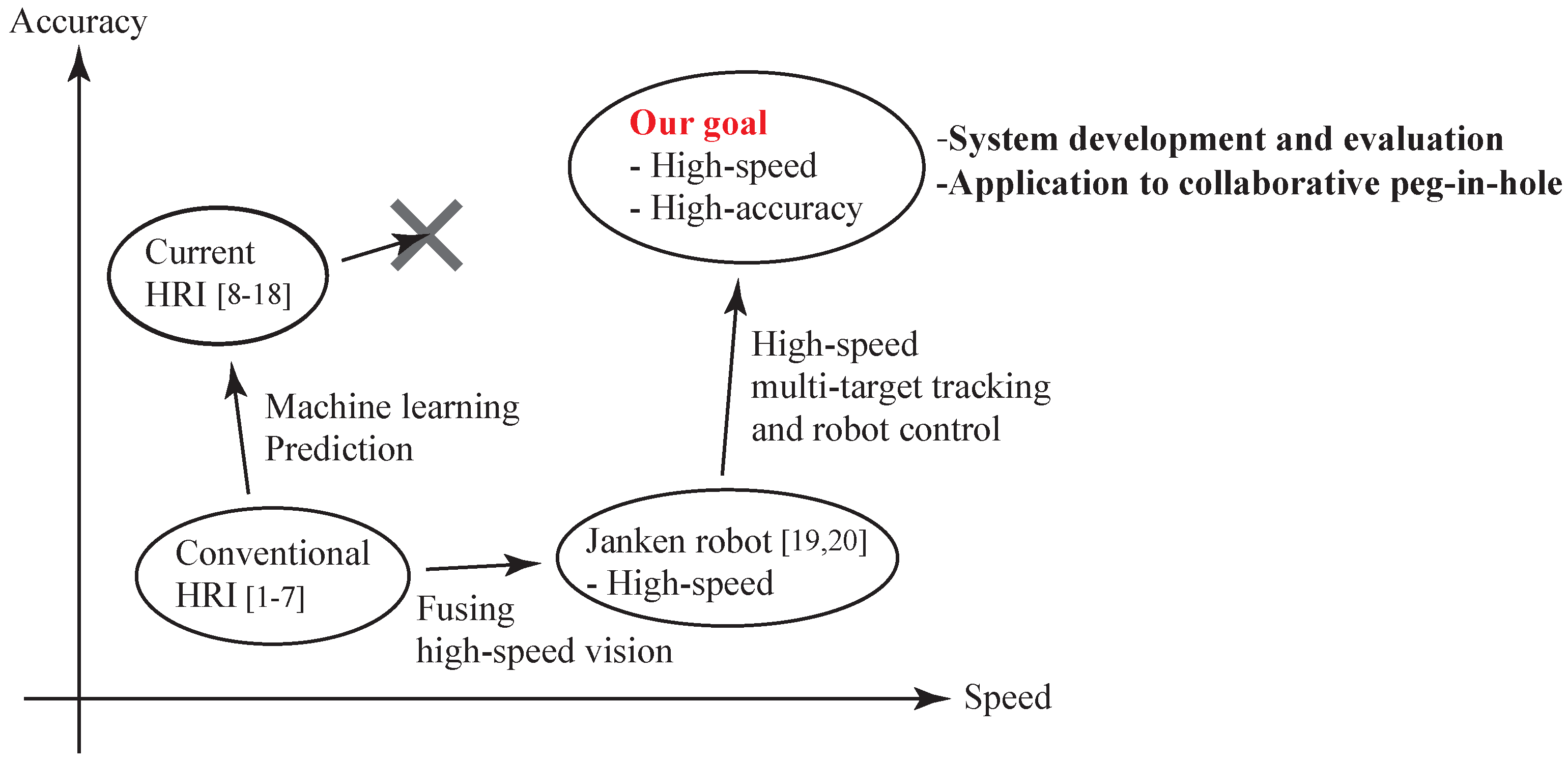
:1. Introduction
- Collaboration and cooperation,
- Communication, and
- Support and assistance.
- The construction of a high-speed and high-accuracy Human-Robot collaborative system,
- The proposed strategy for high-speed visual sensing and robot control in a high-speed and high-accuracy Human-Robot collaborative system,
- The stability analysis of the high-speed and high-accuracy Human-Robot collaborative system,
- The theoretical analysis of the collaborative error due to image processing and latency,
- The experimental evaluation of the collaborative error and control performance (torque inputs) of the robot hand,
- The analysis of the peg-in-hole task performed by the collaborative system, and
- Te demonstration of a concrete application (peg-in-hole task) via Human-Robot collaboration.
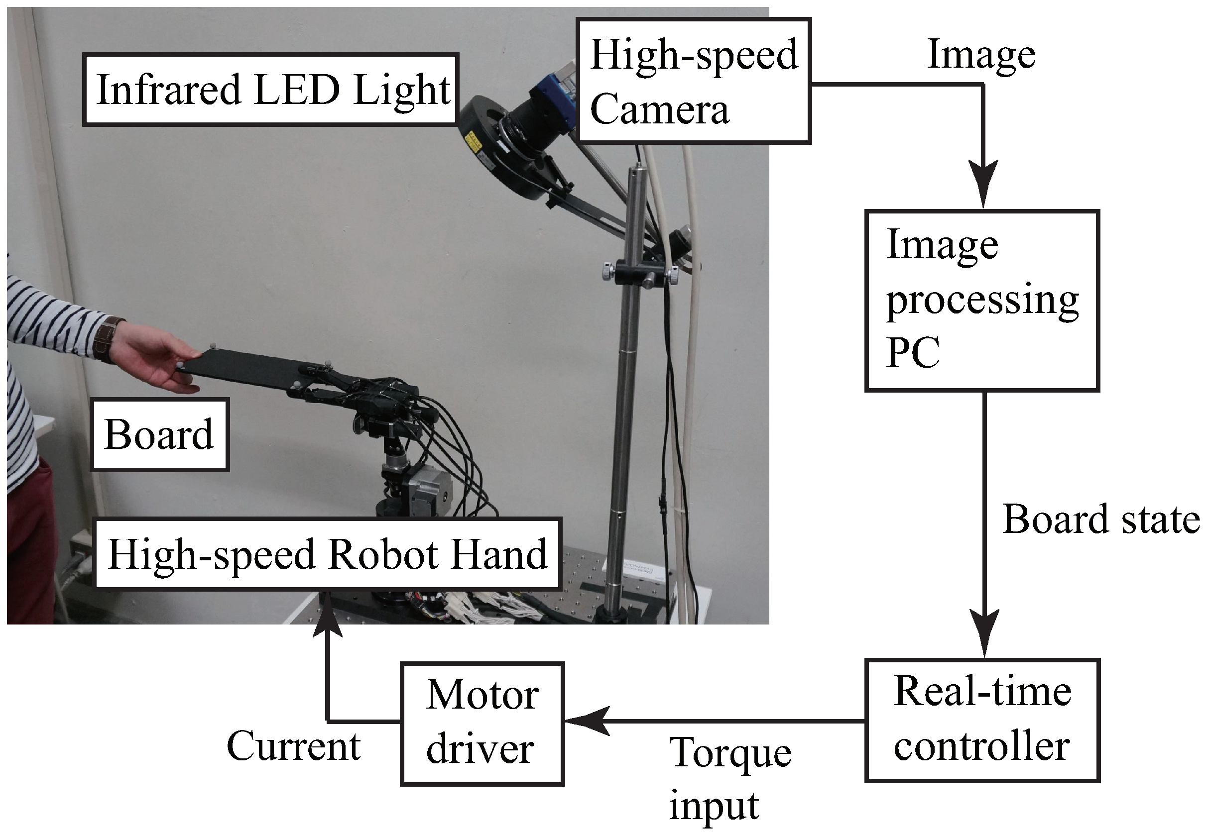
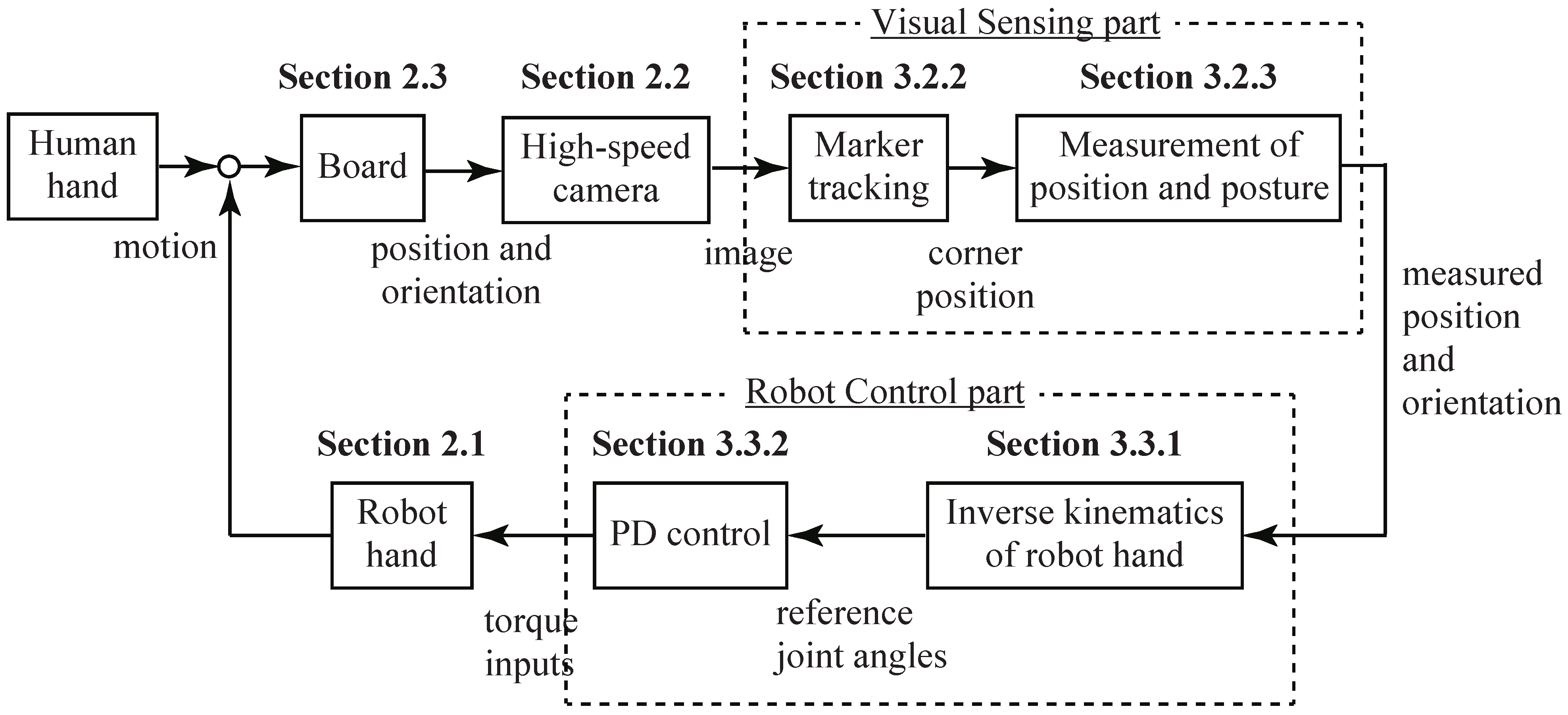
2. Human-Robot Collaborative System
- A high-speed robot hand (Section 2.1),
- A high-speed vision system (Section 2.2),
- A real-time controller that receives the state values of the board (position and orientation) from the image-processing PC at 1 kHz and also controls the high-speed robot hand at 1 kHz,
- A board that is handled by the robot hand and a human subject (Section 2.3), and
- A peg (Section 2.4).
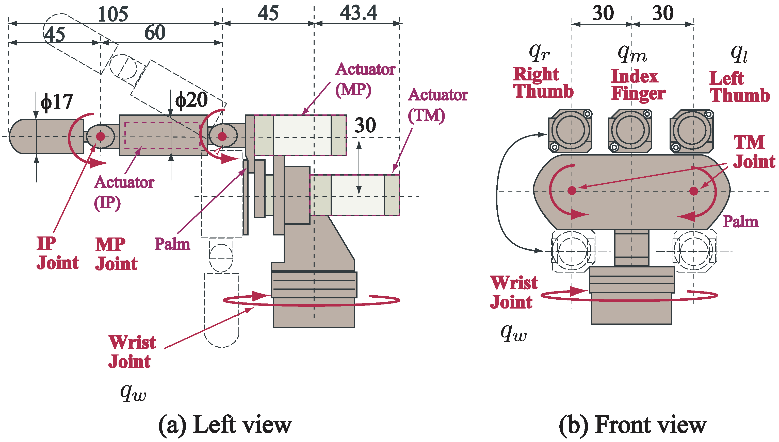
2.1. High-Speed Robot Hand
2.2. High-Speed Vision System
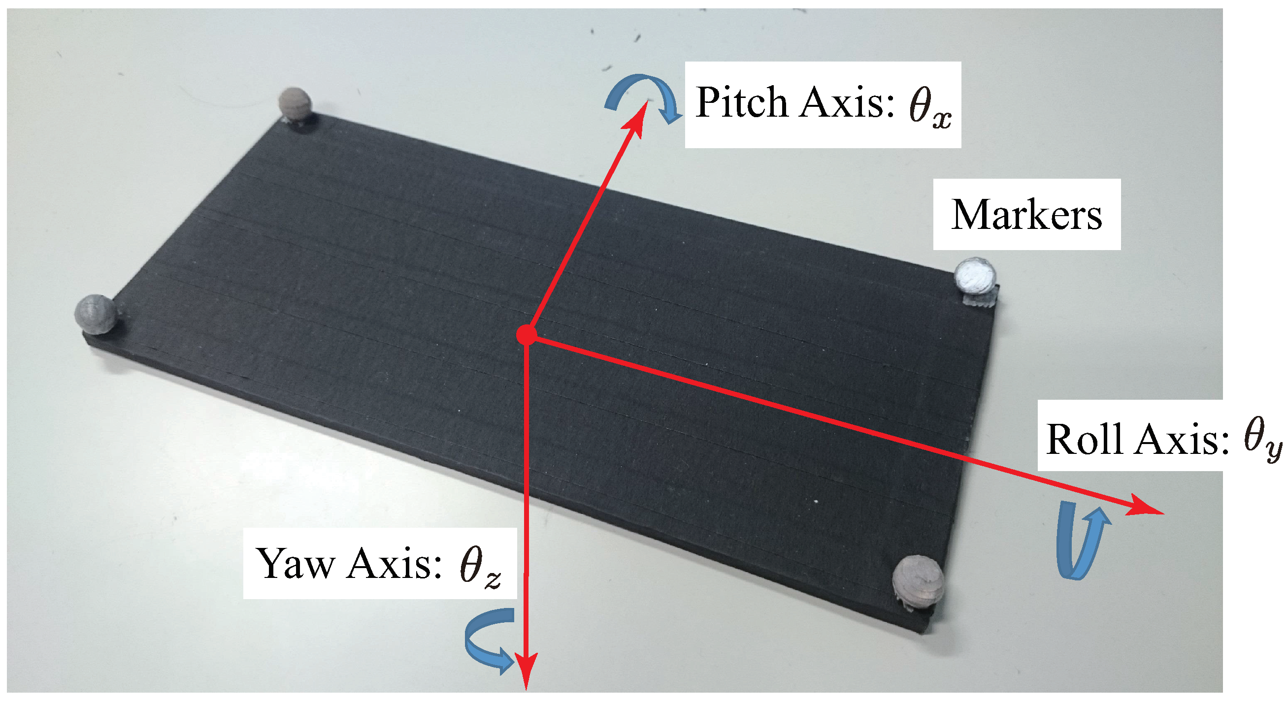
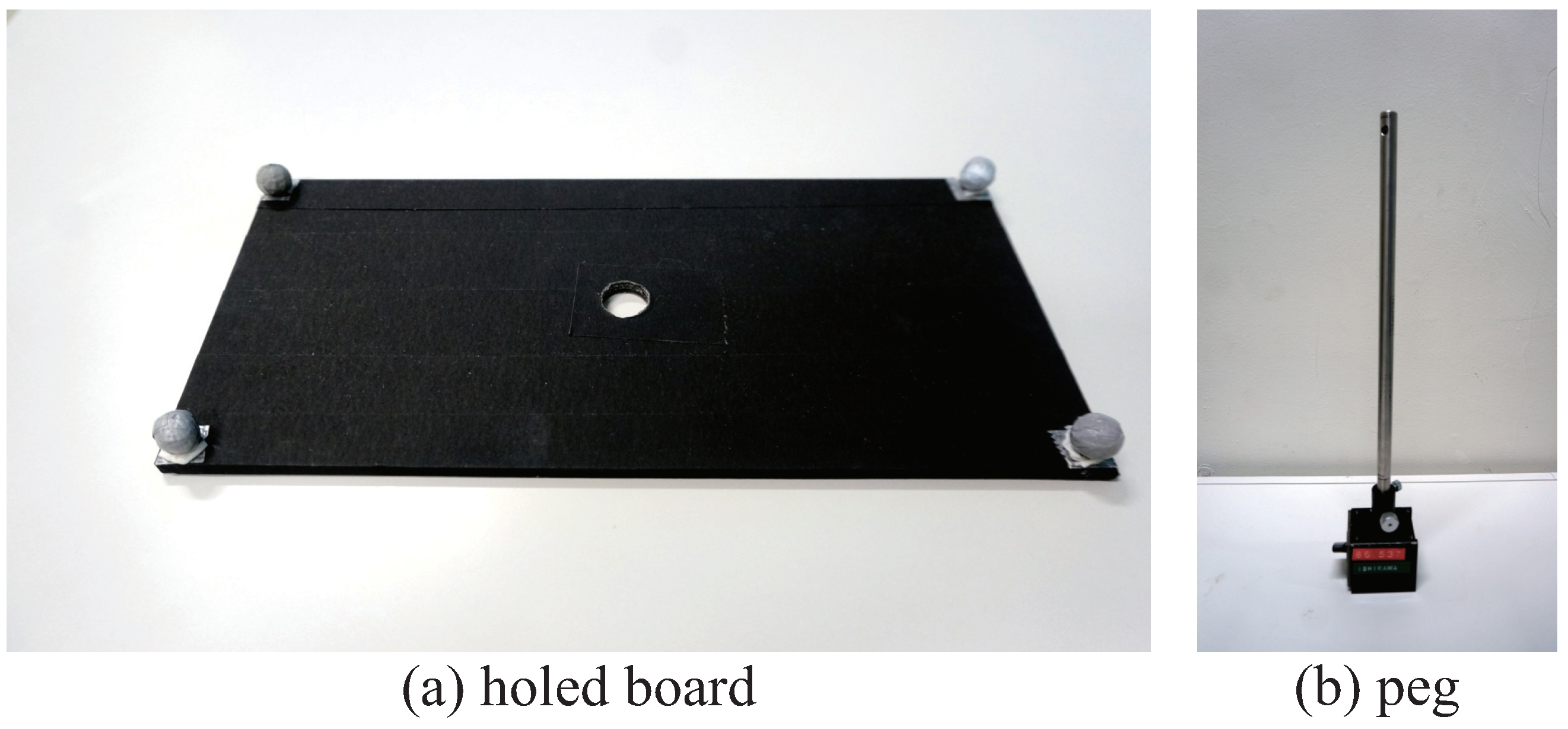
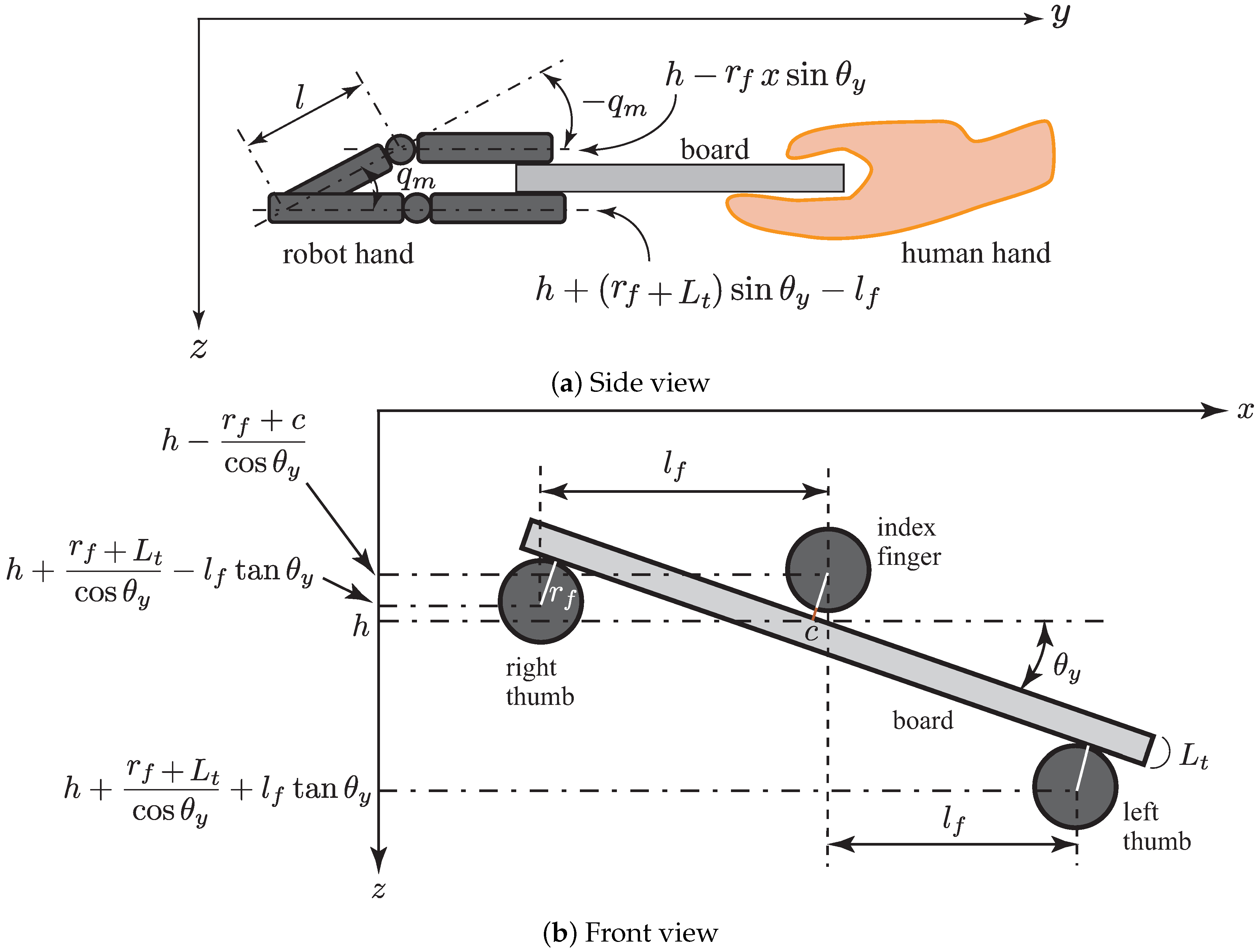
2.3. Board with Hole as a Target Object
2.4. Peg
3. Strategy for Collaborative Motion
- The human subject moved the board,
- The board position and orientation were changed as a result of the human operation,
- The high-speed camera captured the image,
- The tracking of the markers attached to the four corners of the board was executed by image-processing,
- The position and posture of the board were calculated based on the information of the marker positions,
- The reference joint angle of the robot hand was obtained by solving the inverse kinematics of the robot hand based on the position and posture of the board,
- The torque to be input to the servo motor of the robot hand was generated by proportional derivative (PD) control for the reference joint angle, and
- The robot hand moved according to the torque input.
3.1. Brief Overview
- Visual Sensing part in Figure 7: The position and orientation of the board were measured using high-speed image processing (Section 3.2).
- Robot Control part in Figure 7: The robot hand was controlled according to the position and orientation of the board (Section 3.3).
3.2. Image Processing and Measurement of Position and Orientation of Board
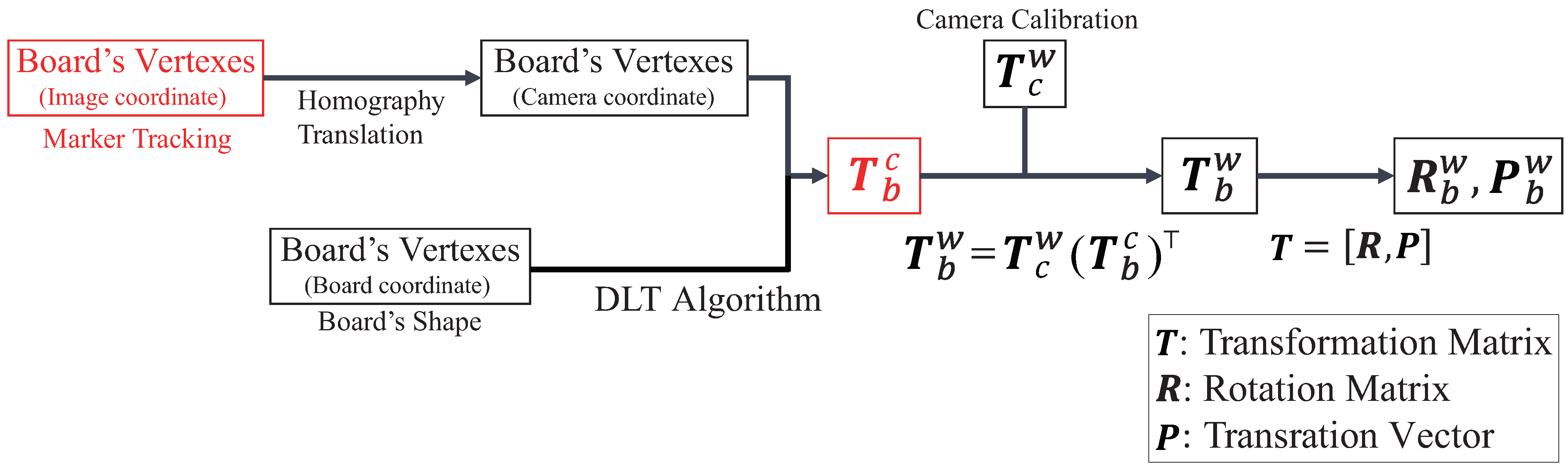
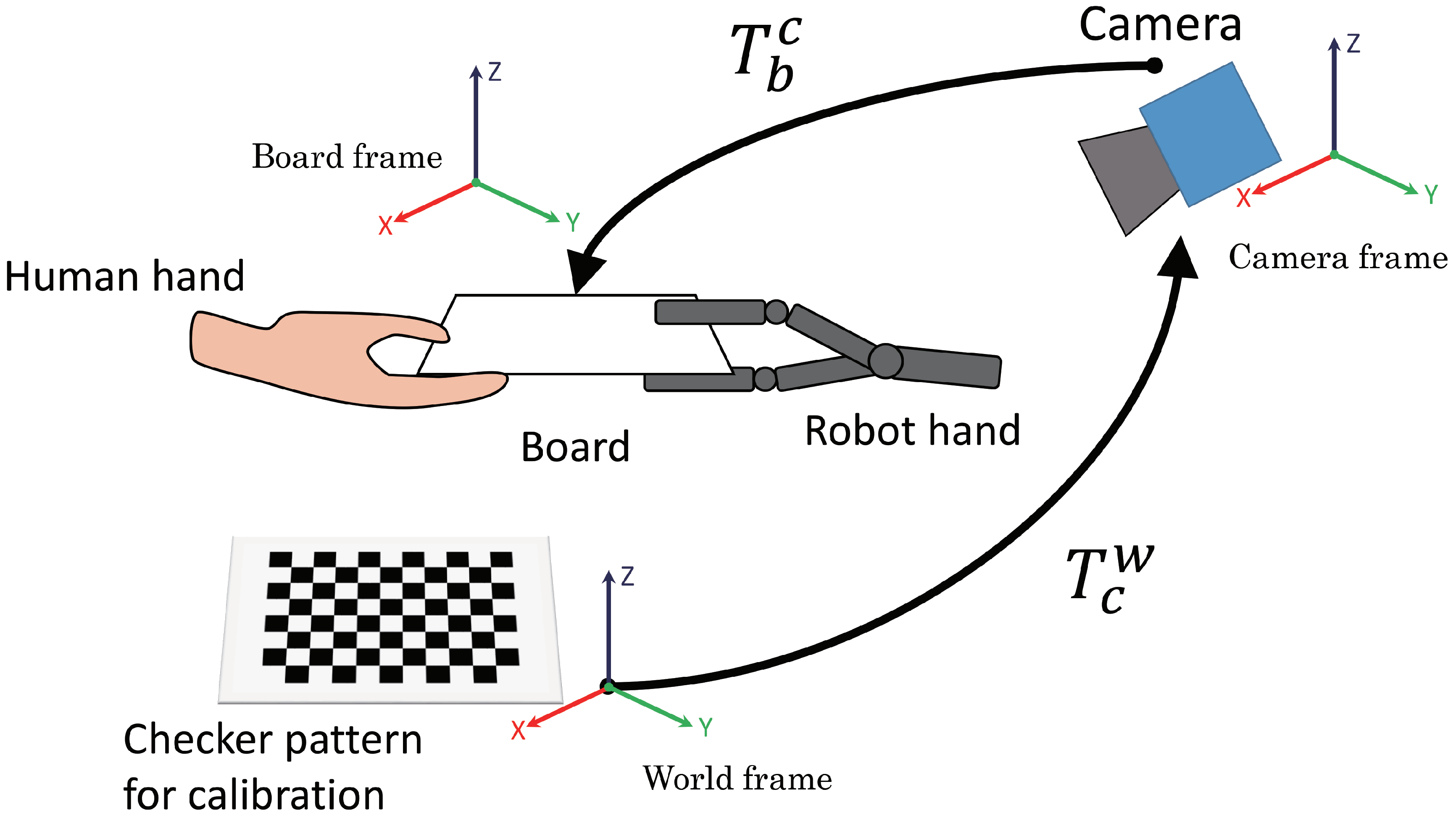
3.2.1. Derivation of Transformation Matrix
3.2.2. Marker Tracking
3.2.3. Measurement of Board Position and Orientation in World Coordinates
3.3. Robot Hand Control
3.3.1. Inverse Kinematics of the Robot Hand
3.3.2. Joint Angle Control of the Robot Hand
3.4. Advantages and Limitations of Proposed Method
4. Theoretical Analysis
4.1. Stability Analysis
4.2. Analysis of Collaborative Error
4.2.1. Collaborative Error Due to Image-Processing
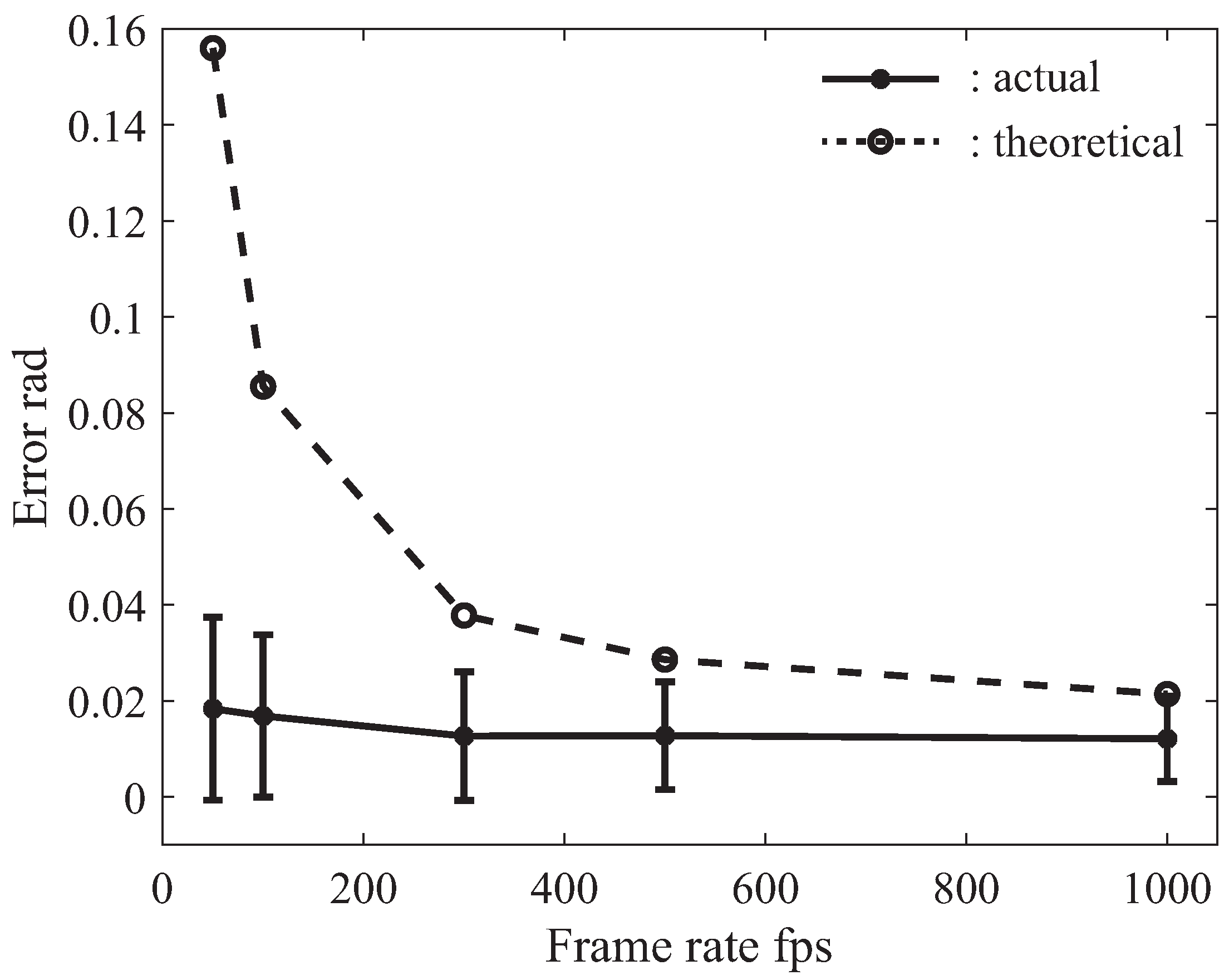
4.2.2. Collaborative Error Due to Frame Rate
5. Experiment for Collaborative Motion Task
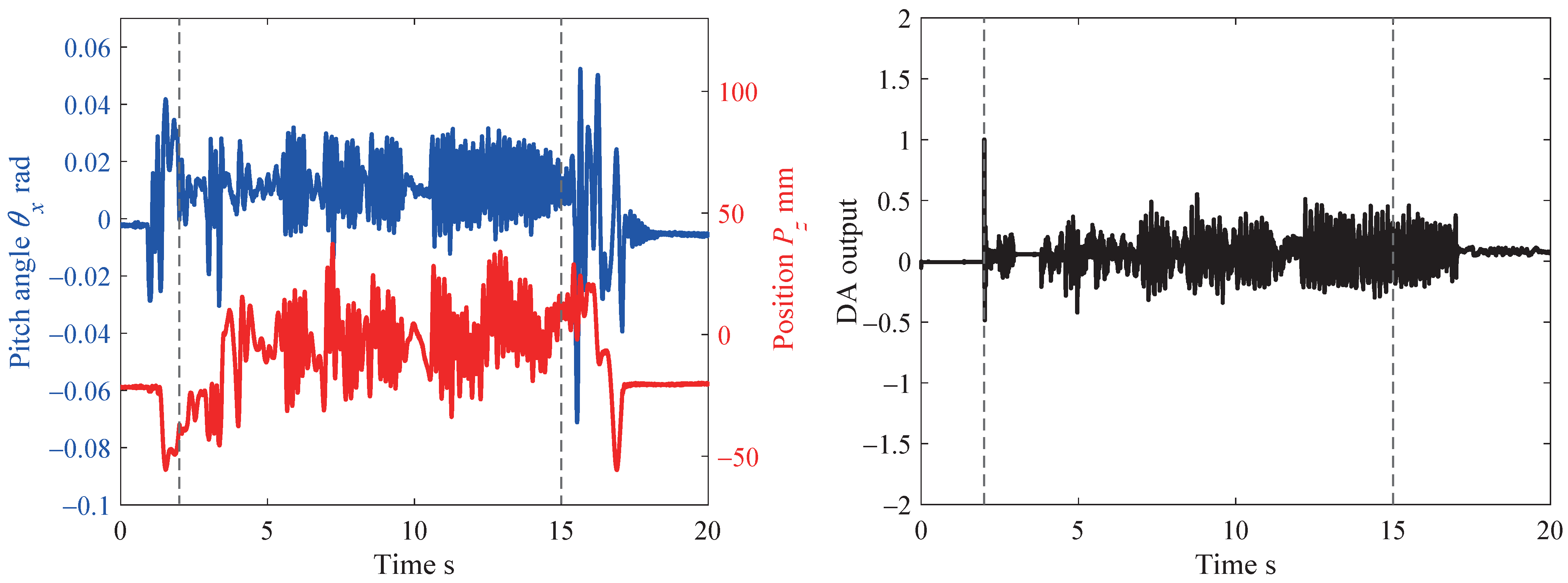
5.1. Result
5.2. Evaluation
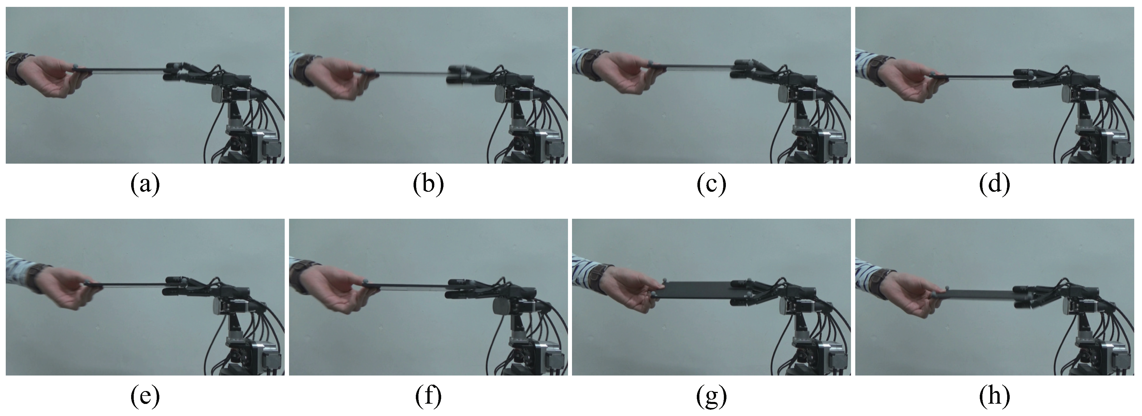
6. Collaborative Peg-In-Hole Task
6.1. Conditions for Achieving Collaborative Peg-In-Hole Task
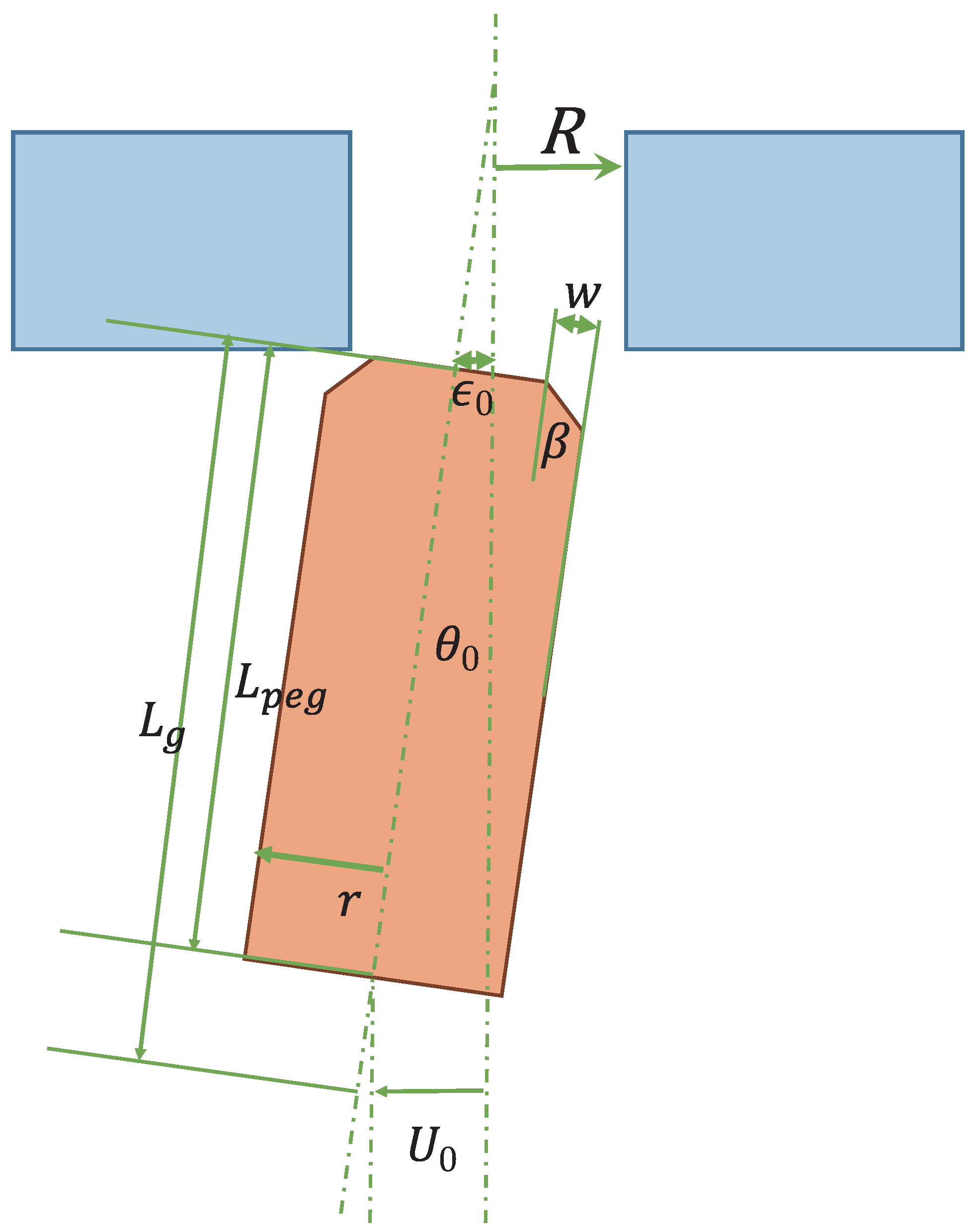
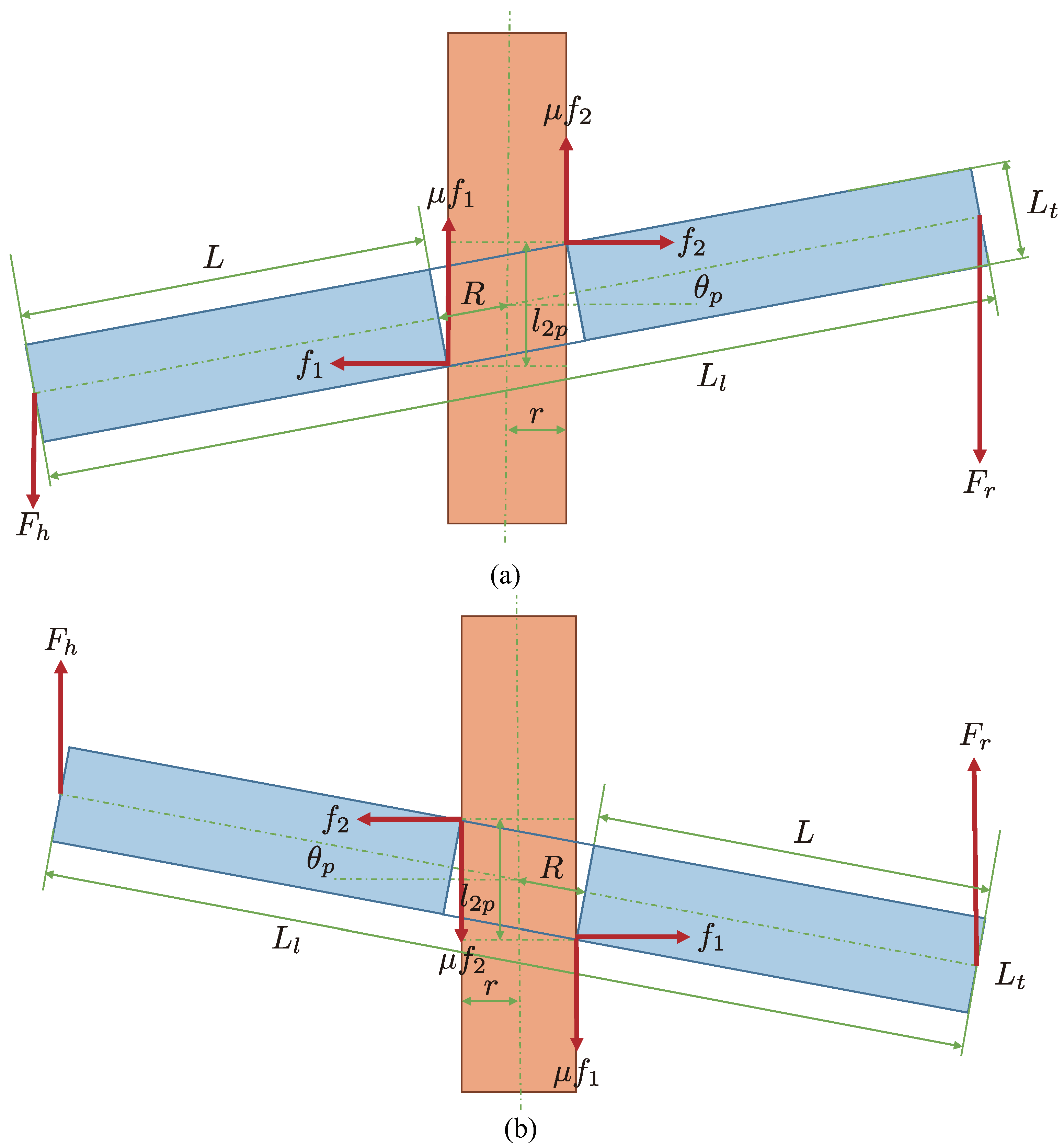
6.1.1. Geometric Conditions
6.1.2. Force Condition
6.1.3. Posture Condition
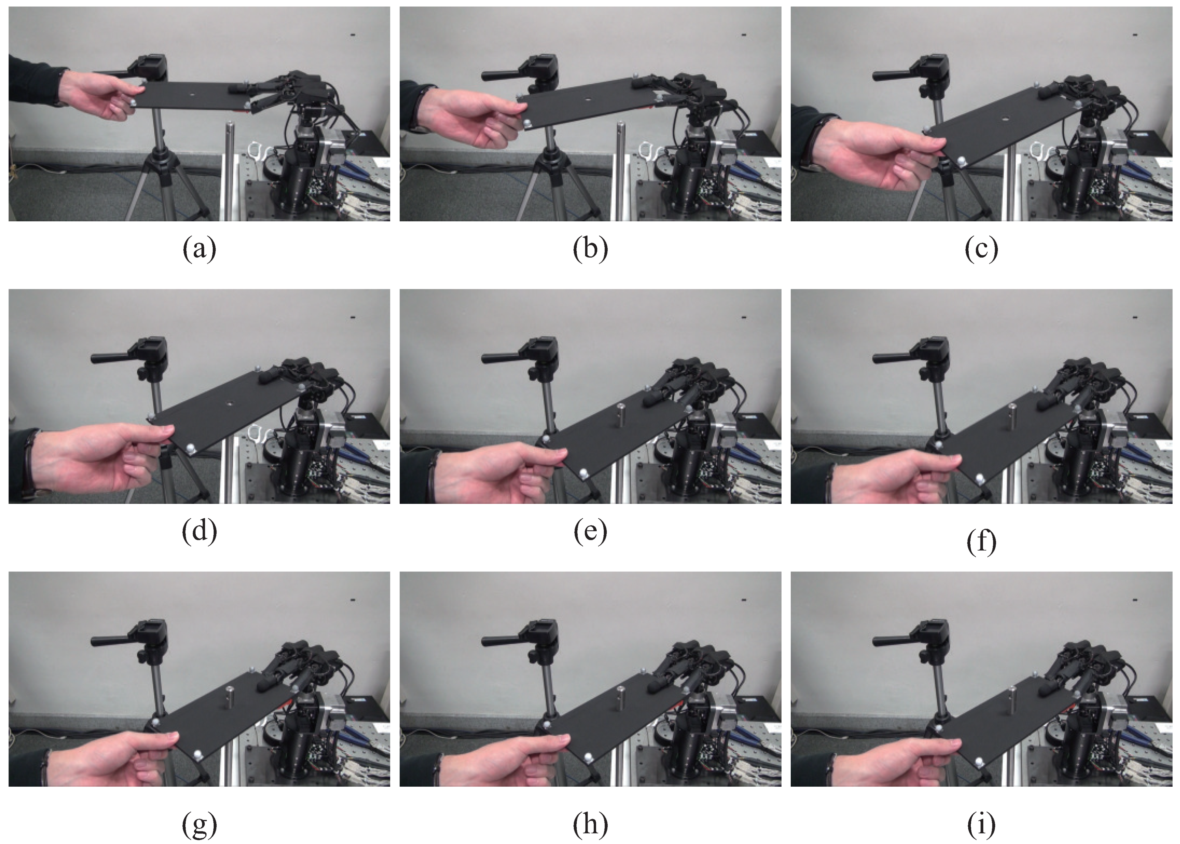
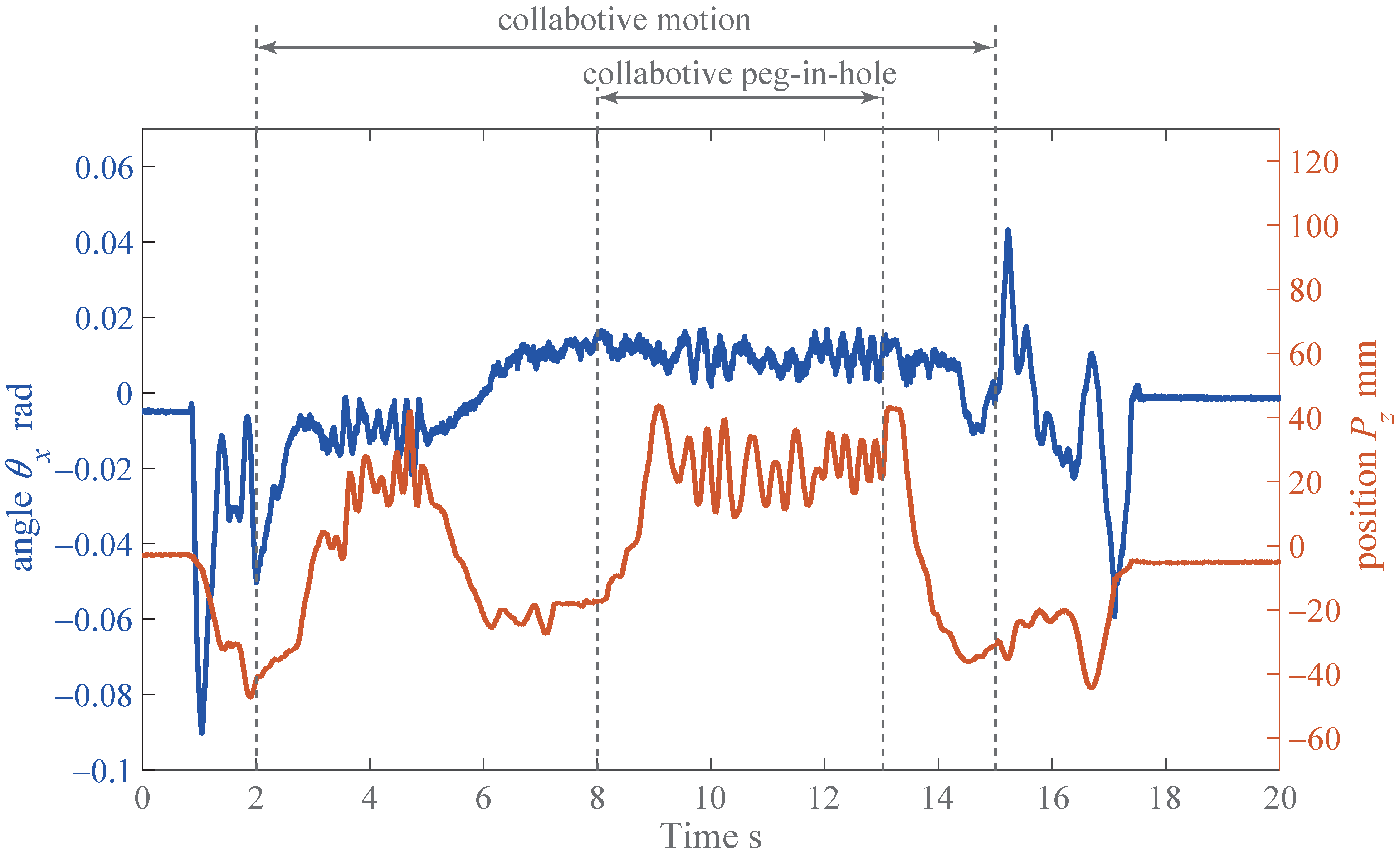
6.2. Experimental Result
7. Conclusions
Author Contributions
Funding
Conflicts of Interest
References
- Chandrasekaran, B.; Conrad, M.J. Human-robot collaboration: A survey. In Proceedings of the IEEE SoutheastCon 2015, Fort Lauderdale, FL, USA, 9–12 April 2015; pp. 1–8. [Google Scholar]
- Zoss, A.B.; Kazerooni, H.; Chu, A. Biomechanical design of the berkeley lower extremity exoskeleton (bleex). IEEE/ASME Trans. Mechatron. 2006, 11, 128–138. [Google Scholar] [CrossRef]
- Hayashibara, Y.; Takubo, T.; Sonoda, Y.; Arai, H.; Tanie, K. Assist system for carrying a long object with a human-analysis of a human cooperative behavior in the vertical direction. In Proceedings of the 1999 IEEE/RSJ International Conference on Intelligent Robots and Systems, Kyongju, Korea, 17–21 October 1999; pp. 695–700. [Google Scholar]
- Yokoyama, K.; Handa, H.; Isozumi, T.; Fukase, Y.; Kaneko, K.; Kanehiro, F.; Kawai, Y.; Tomita, F.; Hirukawa, H. Cooperative works by a human and a humanoid robot. In Proceedings of the 2003 IEEE International Conference on Robotics and Automation, Taipei, Taiwan, 14–19 September 2003; pp. 2985–2991. [Google Scholar]
- Kosuge, K.; Kakuya, H.; Hirata, Y. Control algorithm of dual arms mobile robot for cooperative works with human. In Proceedings of the 2001 IEEE International Conference on Systems, Man, and Cybernetics, Tucson, AZ, USA, 7–10 October 2001; pp. 3223–3228. [Google Scholar]
- Suda, R.; Kosuge, K. Handling of object by mobile robot helper in cooperation with a human using visual information and force information. In Proceedings of the 2002 IEEE/RSJ International Conference on Intelligent Robots and Systems, Lausanne, Switzerland, 30 September–4 October 2002; pp. 1102–1107. [Google Scholar]
- Stückler, J.; Behnke, S. Following human guidance to cooperatively carry a large object. In Proceedings of the 11th IEEE-RAS International Conference on Humanoid Robots, Bled, Slovenia, 26–28 October 2011; pp. 218–223. [Google Scholar]
- Antão, L.; Pinto, R.; Reis, J.; Gonçalves, G.; Pereira, F.L. Cooperative human-machine interaction in industrial environments. In Proceedings of the 2018 13th APCA International Conference on Automatic Control and Soft Computing, Ponta Delgada, Portugal, 4–6 June 2018; pp. 430–435. [Google Scholar]
- Teke, B.; Lanz, M.; Kämäräinen, J.; Hietanen, A. Real-time and robust collaborative robot motion control with Microsoft Kinect® v2. In Proceedings of the 2018 14th IEEE/ASME International Conference on Mechatronic and Embedded Systems and Applications, Oulu, Finland, 2–4 July 2018; pp. 1–6. [Google Scholar]
- Çoban, M.; Gelen, G. Realization of human-robot collaboration in hybrid assembly systems by using wearable technology. In Proceedings of the 2018 6th International Conference on Control Engineering & Information Technology, Istanbul, Turkey, 25–27 October 2018; pp. 1–6. [Google Scholar]
- Wang, W.; Li, R.; Chen, Y.; Diekel, Z.M.; Jia, Y. Facilitating human-robot collaborative tasks by teaching-learning-collaboration from human demonstrations. IEEE Trans. Autom. Sci. Eng. 2019, 16, 640–653. [Google Scholar] [CrossRef]
- Shayganfar, M.; Rich, C.; Sidner, C. Appraisal algorithms for relevance and controllability in human-robot collaboration. In Proceedings of the 2019 IEEE International Conference on Humanized Computing and Communication, Laguna Hills, CA, USA, 25–27 September 2019; pp. 31–37. [Google Scholar]
- Scimmi, L.S.; Melchiorre, M.; Mauro, S.; Pastorelli, S. Experimental real-time setup for vision driven hand-over with a collaborative robot. In Proceedings of the 2019 International Conference on Control, Automation and Diagnosis, Grenoble, France, 2–4 July 2019; pp. 1–5. [Google Scholar]
- Galin, R.; Meshcheryakov, R.; Samoshina, A. Mathematical modelling and simulation of human-robot collaboration. In Proceedings of the 2020 International Russian Automation Conference, Sochi, Russia, 6–12 September 2020; pp. 1058–1062. [Google Scholar]
- Darvish, K.; Simetti, E.; Mastrogiovanni, F.; Casalino, G. A Hierarchical architecture for human-robot cooperation processes. IEEE Trans. Robot. 2020. [Google Scholar] [CrossRef]
- Muthugala, M.A.V.J.; Srimal, P.H.D.A.S.; Jayasekara, A.G.B.P. Improving robot’s perception of uncertain spatial descriptors in navigational instructions by evaluating influential gesture notions. J. Multimodal User Interfaces 2020. [Google Scholar] [CrossRef]
- Sheng, W.; Thobbi, A.; Gu, Y. An integrated framework for human-robot collaborative manipulation. IEEE Trans. Cybern. 2015, 45, 2030–2041. [Google Scholar] [CrossRef]
- Lemmerz, K.; Glogowski, P.; Kleineberg, P.; Hypki, A.; Kuhlenkötter, B. A hybrid collaborative operation for human-robot interaction supported by machine learning. In Proceedings of the 2019 12th International Conference on Human System Interaction, Richmond, VA, USA, 25–27 June 2019; pp. 69–75. [Google Scholar]
- Ishikawa Group Laboratory. Available online: http://www.k2.t.u-tokyo.ac.jp/fusion/Janken/index-e.html (accessed on 15 December 2020).
- Janken (rock-paper-scissors) robot with 100% winning rate (human-machine cooperation system) in Yamakawa Laboratory. Available online: http://www.hfr.iis.u-tokyo.ac.jp/research/Janken/index-e.html (accessed on 15 December 2020).
- Yamakawa, Y.; Kuno, K.; Ishikawa, M. Human-robot cooperative task realization using high-speed robot hand system. In Proceedings of the 2015 IEEE International Conference on Advanced Intelligent Mechatronics, Busan, Korea, 7–11 July 2015; pp. 281–286. [Google Scholar]
- Matsui, Y.; Yamakawa, Y.; Ishikawa, M. Cooperative operation between a human and a robot based on real-time measurement of location and posture of target object by high-speed vision. In Proceedings of the 2017 IEEE International Conference on Control Technology and Applications, Mauna Lani, HI, USA, 27–30 August 2017; pp. 457–462. [Google Scholar]
- Yamakawa, Y.; Matsui, Y.; Ishikawa, M. Human-robot collaborative manipulation using a high-speed robot hand and a high-speed camera. In Proceedings of the 2018 IEEE International Conference on Cyborg and Bionic Systems, Shenzhen, China, 25–27 October 2018; pp. 426–429. [Google Scholar]
- Yamakawa, Y.; Matsui, Y.; Ishikawa, M. Development and analysis of a high-speed human-robot collaborative system and its application. In Proceedings of the 2018 IEEE International Conference on Robotics and Biomimetics, Kuala Lumpur, Malaysia, 12–15 December 2018; pp. 2415–2420. [Google Scholar]
- Namiki, A.; Imai, Y.; Ishikawa, M.; Kaneko, M. Development of a high-speed multifingered hand system and its application to catching. In Proceedings of the 2003 IEEE/RSJ International Conference on Intelligent Robots and Systems, Las Vegas, NV, USA, 27–31 October 2003; pp. 2666–2671. [Google Scholar]
- MIKROTRON. Available online: http://www.mikrotron.de/ (accessed on 15 December 2020).
- Zhang, Z. A flexible new technique for camera calibration. IEEE Trans. Pattern Anal. Mach. Intell. 2000, 22, 1330–1334. [Google Scholar] [CrossRef] [Green Version]
- Ishii, I.; Nakabo, Y.; Ishikawa, M. Target tracking algorithm for 1 ms visual feedback system using massively parallel processing. In Proceedings of the 1996 IEEE International Conference on Robotics and Automation, Minneapolis, MN, USA, 22–28 April 1996; pp. 2309–2314. [Google Scholar]
- Peternel, L.; Tsagarakis, N.; Caldwell, D.; Ajoudani, A. Adaptation of robot physical behaviour to human fatigue in human-robot co-manipulation. In Proceedings of the 2016 IEEE-RAS 16th International Conference on Humanoid Robots, Cancun, Mexico, 15–17 November 2016; pp. 489–494. [Google Scholar]
- Peternel, L.; Tsagarakis, N.; Ajoudani, A. A human-robot co-manipulation approach based on human sensorimotor information. IEEE Trans. Neural Syst. Rehabil. Eng. 2017, 25, 811–822. [Google Scholar] [CrossRef]
- Rahman, S.M.M.; Ikeura, R. Calibrating intuitive and natural human-robot interaction and performance for power-assisted heavy object manipulation using cognition-based intelligent admittance control schemes. Int. J. Adv. Robot. Syst. 2018, 15, 1–18. [Google Scholar] [CrossRef] [Green Version]
- Dynamic Human-Robot Interactive System in Yamakawa Laboratory. Available online: http://www.hfr.iis.u-tokyo.ac.jp/research/collaboration/index-e.html (accessed on 15 December 2020).
- YouTube. Available online: http://www.youtube.com/watch?v=xB9-vEiZwKY (accessed on 15 December 2020).
- Whitney, D.E. Quasi-static assembly of compliantly supported rigid parts. J. Dyn. Syst. Meas. Control 1982, 104, 65–77. [Google Scholar] [CrossRef]
- Hara, K.; Yokogawa, R.; Kai, Y. Kinematic evaluation of task-performance of a manipulator for a peg-in-hole task: A method of evaluation including a condition for avoidance of jamming on a chamfer). Trans. Jpn. Soc. Mech. Eng. Ser. C 1998, 64, 604–609. [Google Scholar] [CrossRef] [Green Version]
- Muthugala, M.A.V.J.; Jayasekara, A.G.B.P. Enhancing user satisfaction by adapting robot’s perception of uncertain information based on environment and user feedback. IEEE Access 2017, 5, 26435–26447. [Google Scholar] [CrossRef]


| Parameter | Value |
|---|---|
| 0.21 pixel | |
| 0.1 pixel | |
| a | 7 μm/pixel |
| f | 5 mm |
| 800 mm | |
| 220 mm | |
| A | 50 mm |
| 5 Hz |
| Parameter | Value |
|---|---|
| R | 6.350 mm |
| r | 6.325 mm |
| 45° | |
| w | 1 mm |
| 5 mm | |
| 100 mm |
Publisher’s Note: MDPI stays neutral with regard to jurisdictional claims in published maps and institutional affiliations. |
© 2021 by the authors. Licensee MDPI, Basel, Switzerland. This article is an open access article distributed under the terms and conditions of the Creative Commons Attribution (CC BY) license (http://creativecommons.org/licenses/by/4.0/).
Share and Cite
Yamakawa, Y.; Matsui, Y.; Ishikawa, M. Development of a Real-Time Human-Robot Collaborative System Based on 1 kHz Visual Feedback Control and Its Application to a Peg-in-Hole Task . Sensors 2021, 21, 663. https://0-doi-org.brum.beds.ac.uk/10.3390/s21020663
Yamakawa Y, Matsui Y, Ishikawa M. Development of a Real-Time Human-Robot Collaborative System Based on 1 kHz Visual Feedback Control and Its Application to a Peg-in-Hole Task . Sensors. 2021; 21(2):663. https://0-doi-org.brum.beds.ac.uk/10.3390/s21020663
Chicago/Turabian StyleYamakawa, Yuji, Yutaro Matsui, and Masatoshi Ishikawa. 2021. "Development of a Real-Time Human-Robot Collaborative System Based on 1 kHz Visual Feedback Control and Its Application to a Peg-in-Hole Task " Sensors 21, no. 2: 663. https://0-doi-org.brum.beds.ac.uk/10.3390/s21020663