
“Singing” Multilayer Ceramic Capacitors and Mitigation Methods—A Review


Applied Electronics Department, Politehnica University Timisoara, 300006 Timișoara, Romania
*
Author to whom correspondence should be addressed.
Sensors 2022, 22(10), 3869; https://0-doi-org.brum.beds.ac.uk/10.3390/s22103869
Submission received: 29 March 2022
/
Revised: 16 May 2022
/
Accepted: 18 May 2022
/
Published: 19 May 2022
(This article belongs to the Section Intelligent Sensors)
Abstract
:Multilayer Ceramic Capacitors (MLCC) have a major role in modern electronic devices due to their small price and size, large range of capacitance, small ESL and ESR, and good frequency response. Unfortunately, the main dielectric material used for MLCCs, Barium Titanate, makes the capacitors vibrate due to the piezoelectric and electrostrictive effects. This vibration is transferred to the PCB, making it resonate in the audible range of 20 Hz–20 kHz, and in this way the singing capacitors phenomenon occurs. This phenomenon is usually measured with a microphone, to measure the sound pressure level, or with a Laser Doppler Vibrometer (LDV), to measure the vibration. Besides this, other methods are mentioned in the literature, for example, the optical fiber and the active excitation method. There are several solutions to attenuate or even eliminate the acoustic noise caused by MLCC. Specially designed capacitors for low acoustic levels and different layout geometries are only two options found in the literature. To prevent the singing capacitor phenomenon, different simulations can be performed, the harmonic analysis being the most popular technique. This paper is an up-to-date review of the acoustic noise caused by MLCCs in electronic devices, containing measurements methodologies, solutions, and simulation methods.
1. Introduction
Capacitors are passive electronic components found in various shapes and using different materials [1]. Numerous ceramic capacitors, especially multilayer ceramic capacitors (MLCC), are used on a modern printed circuit board (PCB). They have a major role in resonant circuits, power supply bypass, and filters [2]. This makes them indispensable in all modern electronic devices, including but not limited to wearable smart sensors, environmental monitoring, agriculture, and food control, to name a few. Due to their popularity, the global market of MLCCs was valued at USD 5315 million in 2017 and it is predicted to increase to USD 7833 million by 2024 [3,4].
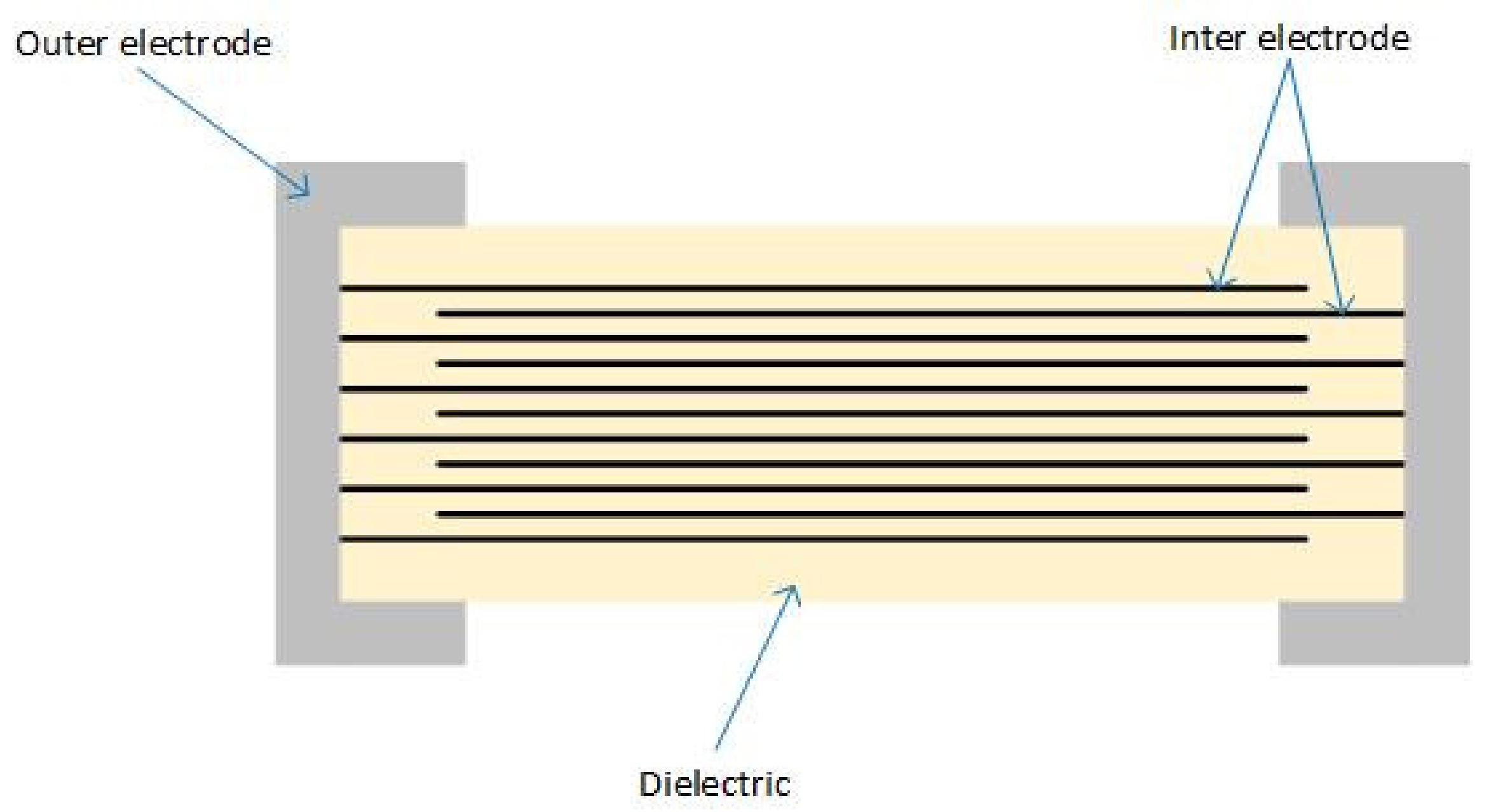
As presented in Figure 1, MLCCs are composed of three main elements: inner electrode, outer electrode, and ceramic dielectric material, mainly made of nickel, silver, and palladium [5].
The main advantages of the MLCCs are their small size and price [6]. Despite their small size, they have large capacitance and favorable electrical characteristics. These characteristics are small equivalent series inductance (ESL), small equivalent series resistance (ESR), good frequency response, a wide range of capacitance value, and their ability to be used for long periods at high temperature or in high-voltage applications [7,8,9].
All of these MLCCs advantages are due to the high-level permittivity dielectric material, Barium Titanate (BaTiO3), they are made of [10,11,12]. Ironically, the two main electro-mechanical properties of the BaTiO3 cause one of the newest problems in electronic devices: the singing capacitors phenomenon [13]. These properties are piezoelectricity and electrostriction. When an AC voltage is applied to the MLCC, the capacitor starts to vibrate due to the piezoelectricity. At the same time, the electric field generated between the inner electrodes creates electrostrictive vibration whose level is similar to the piezoelectric vibration level. Furthermore, the nonlinear phenomenon of the electrostriction also makes a second harmonic frequency vibration of the applied voltage [13]. In recent years, the thickness of the hundreds of dielectric layers present in an MLCC has decreased to achieve a large capacitance in a small package size [1]. Therefore, both properties must be taken into consideration, as the vibration generated by the piezoelectric effect is proportional to the electric field, and the vibration generated by the electrostriction is proportional to the square of the electric field [8].
Due to the thin dielectric layer, the x and y direction components of the electric field applied to an MLCC can be ignored. Therefore, in the equation of mechanical strain Equation (1), only the z-direction is taken into consideration [8].
where sz is the mechanical strain, d33 is the piezoelectric coefficient, M33 is the electrostrictive coefficient, and Ez is the applied electric field on the z-direction (the electric field applied on the x and y directions, Ex and Ey, respectively, can be neglected) [1,8,13,14].
In general, the electric signal applied on MLCC has DC and AC components, as shown in Equation (2). In this case, the mechanical strain equation is expressed using Equations (3) and (4) [1,8,13,14].
As shown in Equation (4), although the applied electric field only has a single frequency term, we can observe the deformation at the second harmonic frequency due to the electrostriction. When the DC component is zero (the electrical signal contains only the AC component), the vibration is caused only by piezoelectricity. As the vibration at the fundamental frequency is influenced both by piezoelectricity and electrostriction, the nonlinear characteristic of the MLCC is present only when the DC electric field is not zero [8,14].
The vibration level of the MLCCs depends on the number of the inner layers, the applied voltage, and the piezoelectric coefficient of the dielectric material [10,15]. If we check the capacitance C Formula (5), we can observe that it depends on the number of layers [15]. Therefore, we can declare that the vibration of the MLCC is proportional to the capacitance [7].
where C is the capacitance, ε0 is the permittivity in a vacuum, εr is the relative permittivity of the dielectric, S is the electrode area, d is the dielectric layer thickness, and N is the number of layers [15].
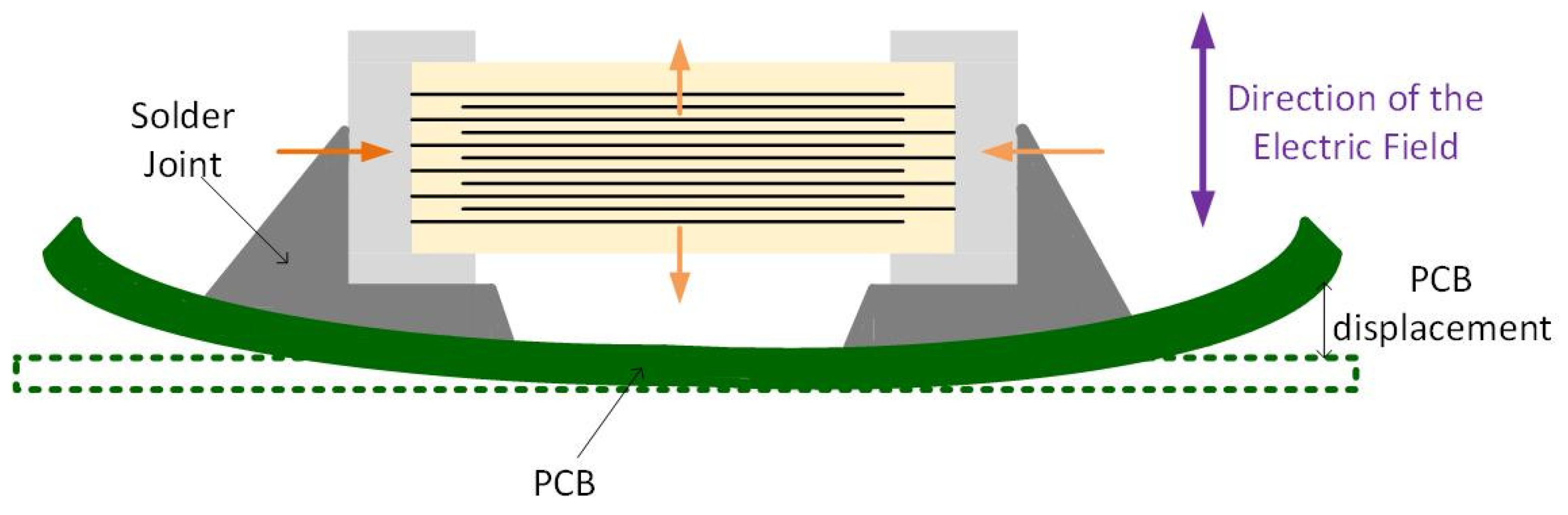
Besides the piezoelectric and electrostrictive effects, the converse magnetoelectric effect also influences the MLCCs behavior. An induced electric polarization that appears under an applied magnetic field characterizes the magnetoelectric effect. On the contrary, the converse magnetoelectric effect is characterized by an induced magnetization under an external electric field [16]. When driven near resonance frequency, the converse magnetoelectric coefficient reaches the maximum [17]. The resonance frequency of the MLCC vibration is in the range of MHz, therefore we should not be able to hear anything. However, as the MLCCs are surface-mount devices (SMD), the induced vibration is transferred to the PCB via solder joint [1,18]. When an AC voltage is applied to the MLCC, the dielectric material expands in the direction of the electric field and contracts in the direction perpendicular to the electric field, causing the deformation of the board, as shown in Figure 2 [4]. Therefore, the PCB starts to vibrate with the MLCC, and the frequency can reach the audible range of 20 Hz–20 kHz [10].
We can conclude that the singing capacitor phenomenon is caused by three major factors [2]:
- the MLCC itself—the capacitor acts as an excitation source;
- the mounting situation—the solder joint is the vibration transfer path;
- the PCB—the board is the acoustic noise resonator.
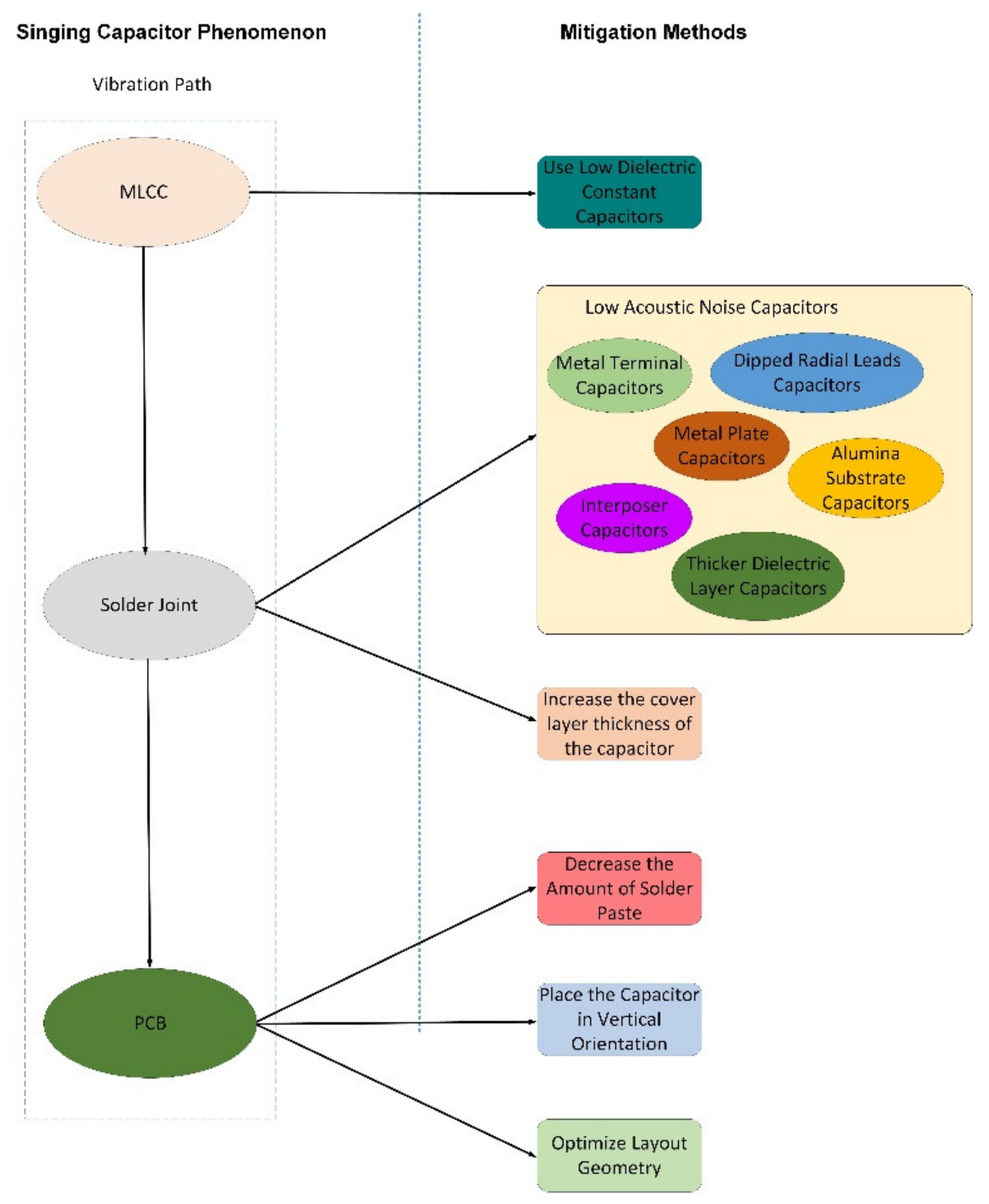
There are several solutions to attenuate or eliminate the acoustic noise caused by MLCCs. Figure 3 highlights the singing capacitor phenomenon and a summary of the possible mitigation solutions. The paper is structured around both aspects.
Some studies suggest that superior dielectric properties are achieved at higher temperatures [19,20]. However, the BaTiO3 material does not present significant variations up to the Curie temperature, around 130 °C [21,22]. In these conditions, we can state that in the normal operation of electronic devices, the acoustic noise caused by MLCCs is not influenced by temperature.
In this paper, a review of the literature information about the singing capacitors phenomenon is presented. In Section 2, we will show how to detect the problematic MLCCs on a PCB. In Section 3, the solutions for singing capacitors found in the literature will be presented, while in Section 4, we will present types of simulation and analysis to prevent audible noise on PCB. We will end with a short discussion about the paper’s highlights and findings.
2. Measurement Methodologies
There are two main ways to measure the singing MLCCs: measure the acoustic noise or the vibration. The best way to characterize acoustic noise is by measuring the sound pressure level (SPL). Usually, this investigation needs a microphone probe, an FFT analyzer, and an anechoic box/room [4]. The microphone has two sensors: one pressure sensor to measure the sound pressure in the air and one velocity sensor to measure the velocity of the motion of the air [9]. The FFT analyzer is used to obtain the SPL spectrum, and the anechoic box is used to reduce the external acoustic noise that might influence the measurement. The SPL is defined as presented in Equation (6) [4,7]:
where PRMS is the root mean square (RMS) deviation from the background atmospheric pressure and P0 is the reference level.
Unfortunately, we cannot identify the problematic capacitors using SPL measurement. For detecting the capacitors which trigger the PCB vibration and produce the acoustic noise, the most suitable solution is scanning the PCB using a Laser Doppler Vibrometer (LDV). It uses the detection Doppler shift of the reflected light to measure the vibration of a surface without contact [4,9]. The LDV has a precise resolution of the submillimeter range, making it suitable for small-size MLCCs measurements.
Measuring the vibration is more convenient and easier to implement than measuring the acoustic noise. Therefore, we can measure the vibration using LDV and after that correlate the results with acoustic noise.
Ko et al. [7] calculated the correlation criteria between acoustic noise and the vibration of the PCB, by measuring the SPL and Vcb on 30 samples. The result was a linear relation represented in Equation (7):
In conclusion, the acoustic noise can be predicted by the vibration response of the PCB. We also know that the electrical signal through the MLCC causes vibration due to the electromechanical characteristics of the BaTiO3. Therefore, it is important to correlate the acoustic noise with the electrical signal.
Another method to measure vibration is an optical fiber sensor. This method measures vibration up to tens of kHz by using glass fiber bundles to illuminate the target and collect the reflected light [23,24], and it is considered suitable due to the optical fiber sensor technology’s high measurement accuracy and lack of electromagnetic interference [25]. Although this method could be used to measure the PCB vibration caused by the MLCCs, the amount of information available in the literature is insufficient. Moreover, the existing papers which study the optical sensor fiber have outdated information. For example, Perrone and Vallan [23] suggest in their article written in 2009 that LDV is not precise enough to measure very small displacements, while Sun et al. [9,10] demonstrate the opposite in their papers written in 2019 and 2020.
Of course, another classical method to measure vibration is a piezoelectric accelerometer [26]. Unfortunately, this cheap and popular sensor can influence the measurement due to its size and weight [23].
Sun et al. [10] proposed two methods to correlate the electrical signal with the acoustic noise while identifying the problematic MLCCs: Active Excitation Method and Vibration and Rail Voltage Coherence Method. The former method detects the problematic MLCCs at specific frequencies with a high level of signal-to-noise ratio. The latter method tracks the transient event on the signal while the system is working in normal operation mode.
During the Activation Excitation Method, the device under test (DUT) is turned OFF, while a signal generator externally excites the MLCCs via an audio power amplifier. The same signal generator is also connected to the vibration control module of an LVD to eliminate the irrelevant vibration signal. The laser head scans each MLCC at different frequencies and the LDV creates a vibration color map. Using this method, we can identify the problematic MLCCs at specific frequencies by observing the MLCC locations with higher vibration strength [10].
Unlike the Activation Excitation Method, the Vibration and Rail Voltage Coherence Method analyses the DUT under normal operation mode to track the effect of the electrical signal transient on the MLCCs. When using this method, the signal’s noise voltage and the MLCC vibration response are examined by a coherence function defined as presented in Equation (8):
where Cxy(f) is the coherence between the voltage signal x(t) and the vibration signal y(t), Gxy(f) is the cross-spectral density between x and y, and Gxx(f) and Gyy(f) are the auto spectral density of x and y, respectively [10].
The coherence value is always subunit, therefore an ideal linear system with x as a single input and y as a single output will be 1, while for a system with x and y completely uncorrelated the value will be 0.
The measurement setup for the Vibration and Rail Voltage Coherence consists of a passive high impedance voltage probe connected to the LDV’s laser controller. The voltage probe accesses the electrical signal through a pair of thin metal wires, so as to not influence the board vibration, and a laser head points to the center of each MLCC.
For each MLCC, the voltage signal spectrum is captured, and the corresponding vibration response is plotted; therefore we can calculate the coherence value at different frequencies. When the coherence value is close to 1, it means that the produced vibration is generated mostly by the electrical signal. When the coherence value is close to 0, it means either that the captured output y is mostly noise, or it has no phase consistency with the input x [10].
In the next chapter, we present several solutions to reduce or eliminate the singing capacitors effect.
3. Solutions
Several solutions are presented in the literature for the singing capacitors phenomenon, such as alternative MLCC types, different orientation and position geometry on PCB, solder joint reduction, and others. Moreover, significant capacitor suppliers are aware of this issue and present methods to attenuate or eliminate the acoustic noise caused by MLCCs. In this chapter, we will go through the solutions currently available.
3.1. MLCC Manufactures Solutions
Murata™ comes with three capacitor series to suppress the singing capacitor phenomenon [27]:
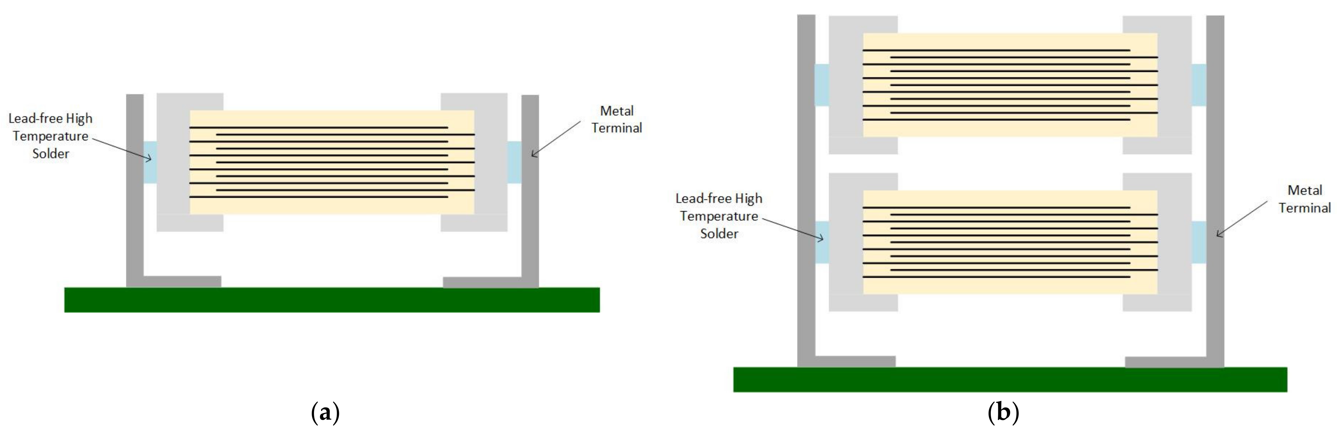
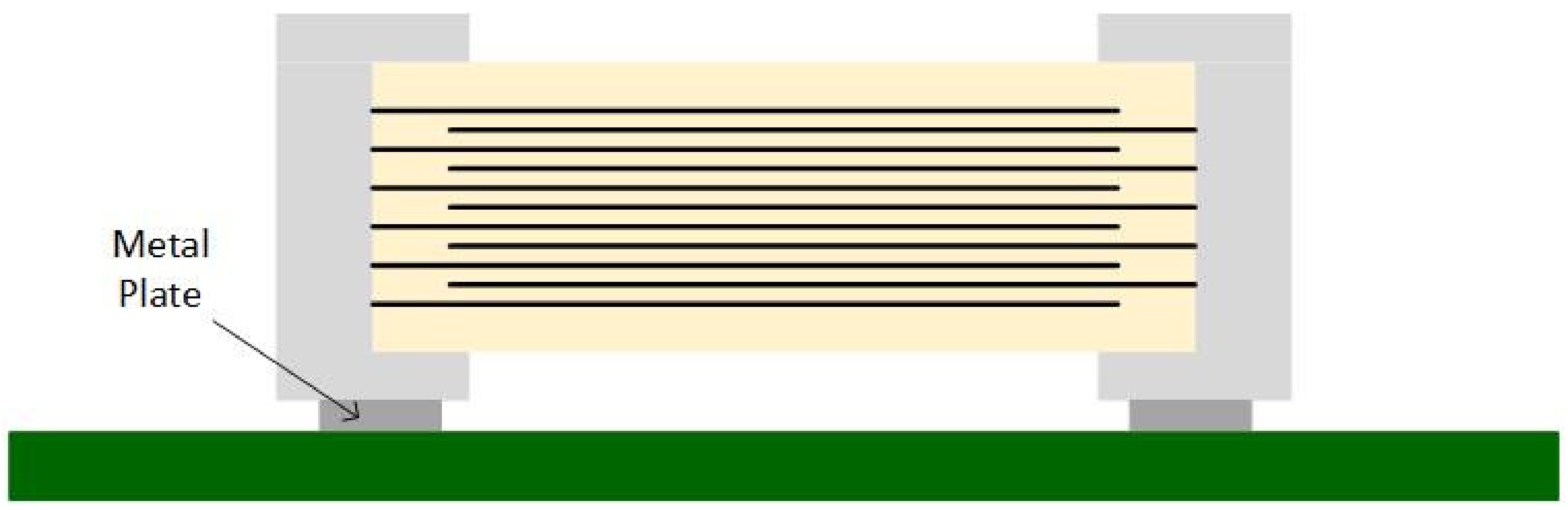
- KRM series—uses metal terminals to raise the capacitor above the PCB (Figure 4a,b);
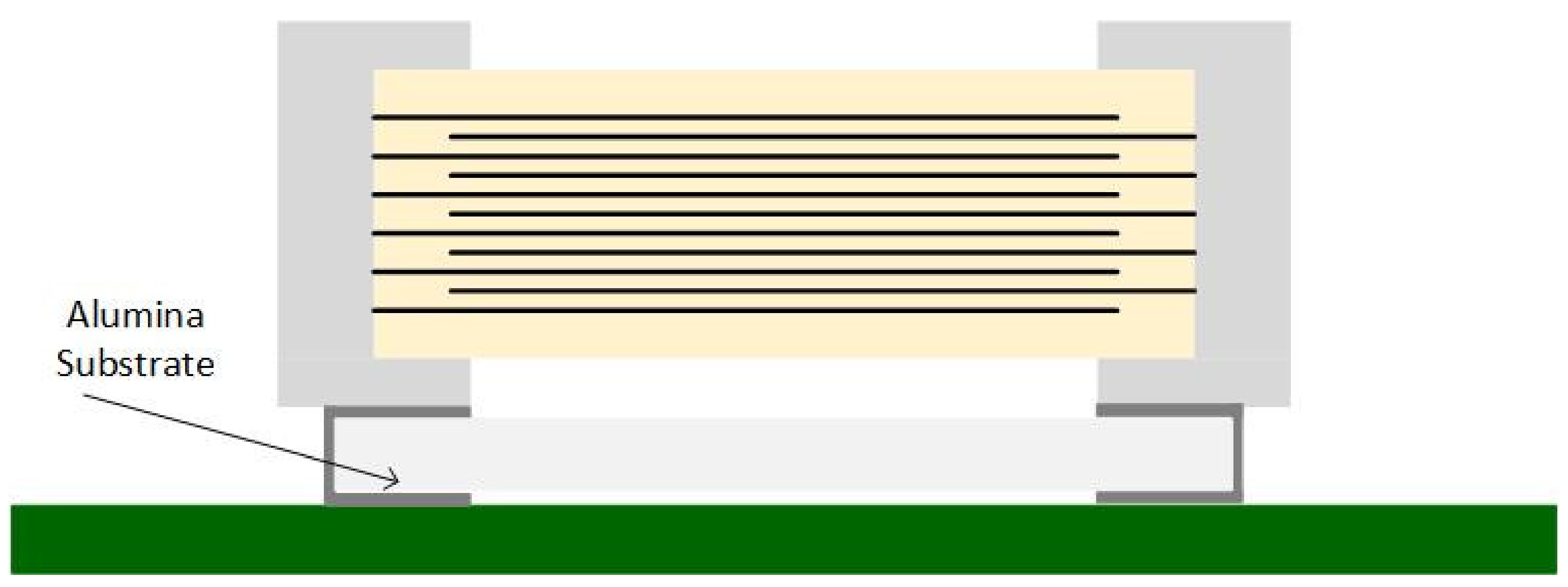
- ZRA/ZRB series—the capacitor is mounted on an interposer substrate that absorbs the vibration before reaching the PCB (Figure 5);
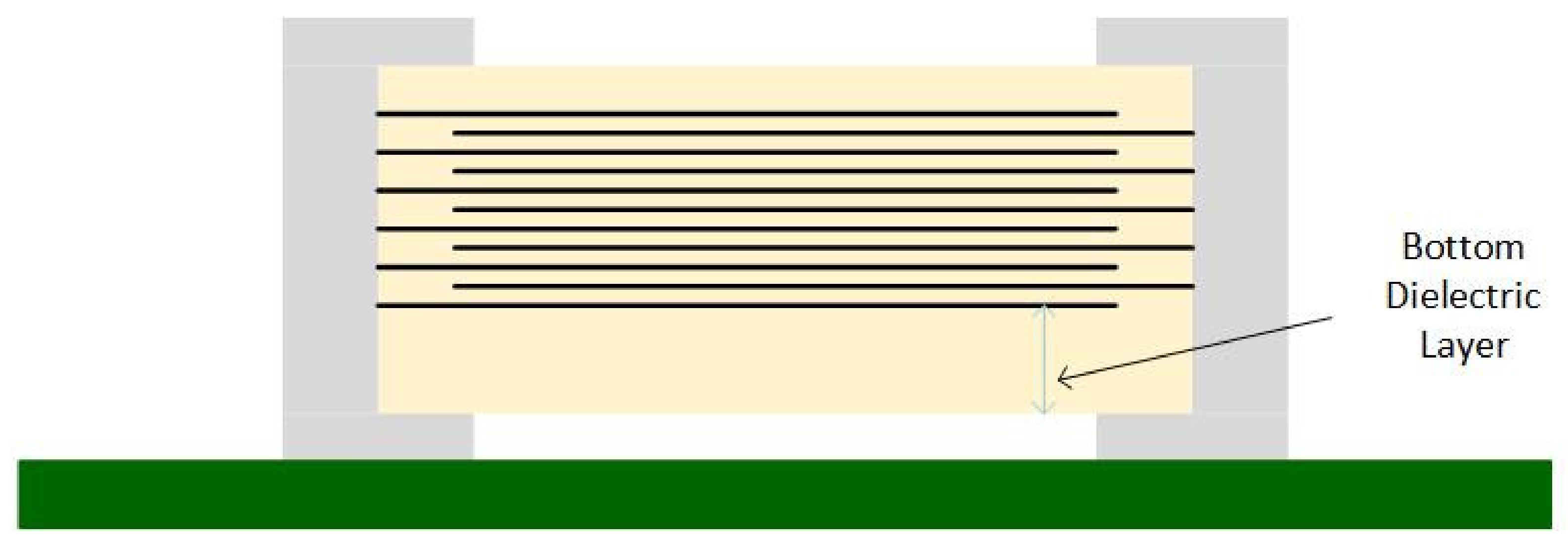
- GJ4 series—uses materials with a lower dielectric constant to attenuate the vibration between the inner layers.
Texas Instruments™ also recommends Murata™’s low acoustic noise MLCCs series. According to Texas Instruments™, by using the low distortion dielectric, acoustic noise is reduced by 7 dB; when using capacitors with an interposer, we eliminate 13 dB; and by using metal terminal capacitors, the noise caused by the MLCC is reduced by 25 dB [28].
Although Murata™’s capacitors are effective, Texas Instruments™ warns users about their high price. Ko et al. [2] not only agree with Texas Instruments’ statement, but also say that using metal terminal capacitors requires additional manufacturing processing steps. Otherwise, the MLCCs may fall off the PCB due to an insufficient amount of solder paste.
Besides using MLCCs designed to suppress acoustic noise, Texas Instruments™ also recommend some design changes, such as shifting the vibration frequency by using a thicker PCB, placing the components at the edge of the PCB, placing the capacitors symmetrically on top and bottom, or improving the load-transient response or line-transient response [28].
Samsung™ also developed three special MLCC series to reduce the singing capacitors phenomenon [29]:
The ANSC-A and ANSC-B series are more efficient than the THMC series due to the separate structure, which isolates the vibration better than the internal dielectric layer. However, the THMC series is more suitable for applications with height limitations [29].
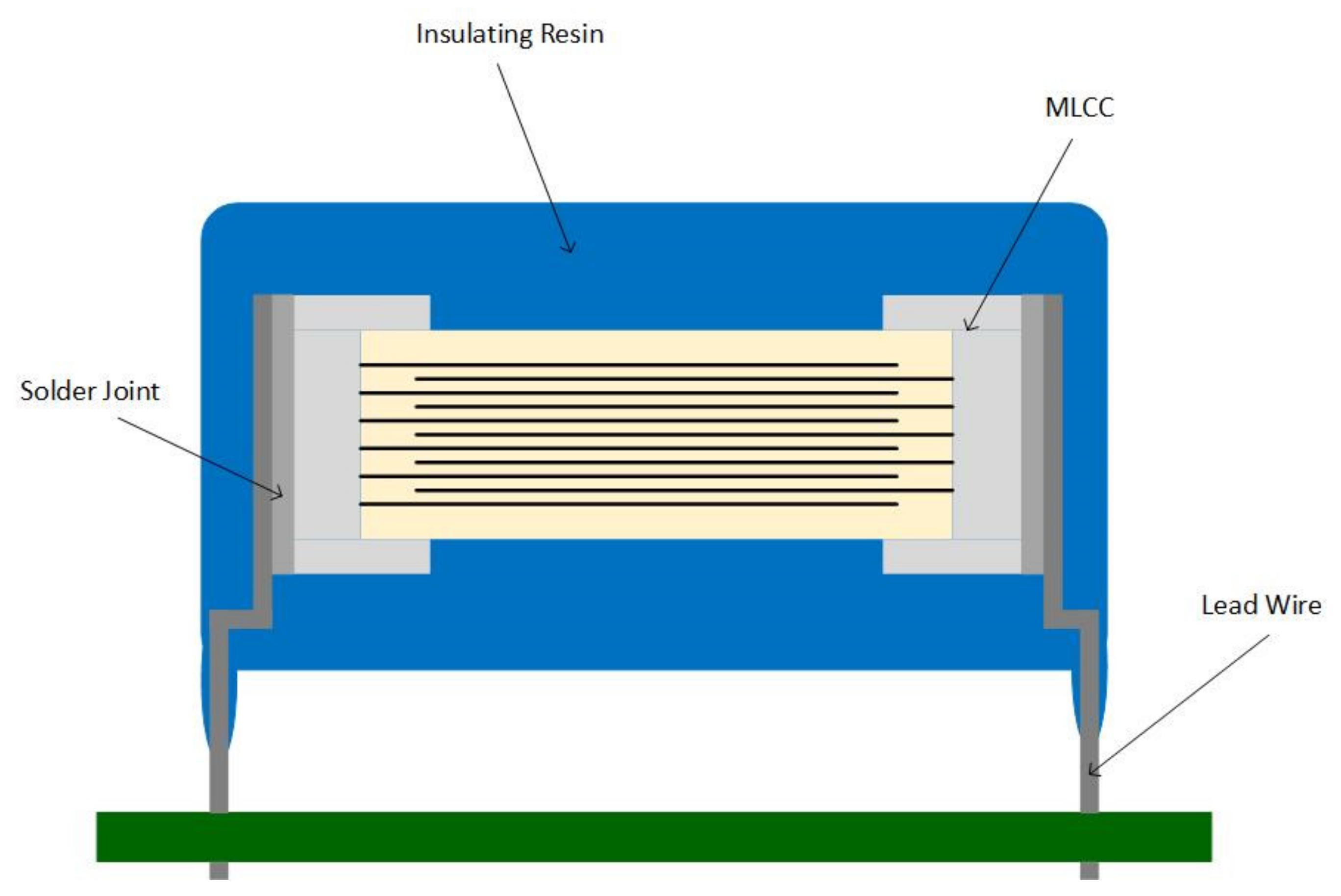
TDK™, on the other hand, offers a halogen-free series with dipped radial leads capacitors. This series consists of resin-coated ceramic capacitors with two lead wires soldered on the terminals, as shown in Figure 9. These capacitors comply with AEC-Q200 automotive standards, are an effective countermeasure against acoustic noise, and alleviate the mechanical and thermal stress on the MLCC [30]. However, the size of the dipped radial leads capacitors and the fact that they are through-hole capacitors makes them unsuitable for designs with dimensions restrictions.
Although these capacitors could be a solution to resolve the singing capacitors phenomenon issue, the price impact is significant, especially if we consider that multiple MLCCs cause the acoustic noise.
3.2. Layout Optimization
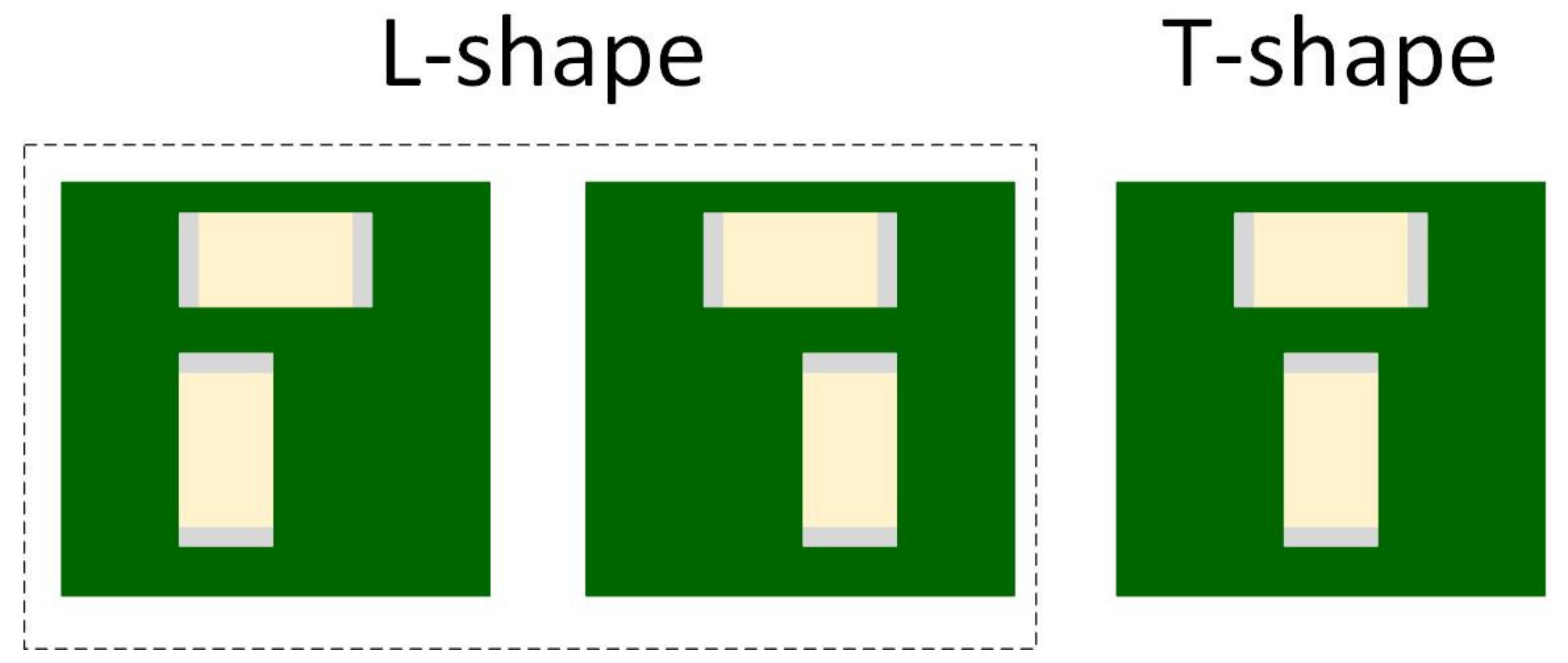
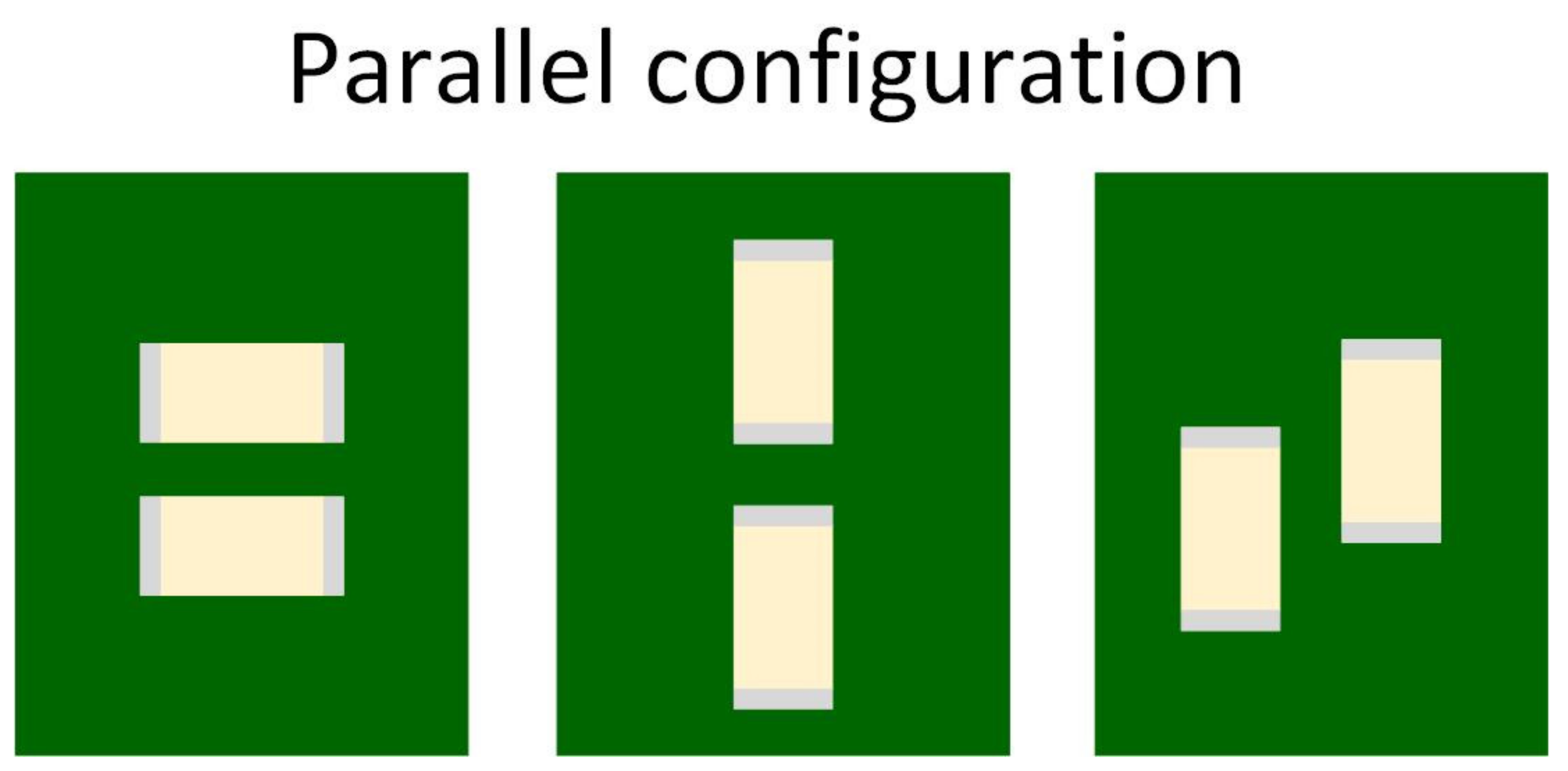
There are several layout configurations for MLCCs. Sun et al. [31] studied three different layout geometries:
The authors of Ref. [31] investigated these geometries using four capacitor types:
- Regular capacitor—standard MLCC shape;
- 3-terminal capacitor—MLCC with an additional terminal, placed between the classical soldering pads;
- Reverse geometry capacitor—MLCC with terminals placed on the longer edge;
- Interposer capacitor—MLCC described in the previous subchapter.
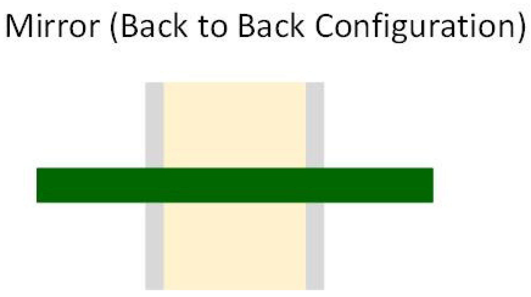
Due to the piezoelectric effect, the MLCC will contract and expand when a voltage is applied. The vibrations caused by two capacitors can be cancelled depending on their relative location and the in-phase or out of phase power ground pins arrangements. When placed in an L-shape or T-shape layout configuration, the vibrations of the two MLCCs are orthogonal to each other and provide a certain level of cancellation. In the parallel layout geometry case, the out of phase power-ground pins configuration allows the PCB vibration cancellation. Due to the top–bottom PCB symmetry, the mirror or back-to-back configuration can cancel the vibration when the voltages are in-phase. During their experiment, Sun et al. [31] applied two sine electrical signals in or out of phase to the MLCCs, and the acoustic noise was measured.
The first observation was that, in comparison with regular capacitor type, the three special types of capacitors reduced the level of acoustic noise up to 10 dB [31]. The reverse geometry type had the smallest impact, while the 3-terminal capacitor and the interposer types had the more significant reduction in noise.
The second observation was that the layout geometry did not have the same effect for all the capacitor types. The results are presented in Table 1 [31]:
Due to the cost implications, the back-to-back configuration is most appreciated in the literature. We can say that, for most applications, the singing capacitors phenomenon is reduced by using the mirror layout geometry and cheap, classical MLCC.
3.3. Other Methodes to Attenute the Singing Capacitors Phenomenon
As stated in the introduction chapter, the solder joint is the vibration transfer path from the MLCC to the PCB. Therefore, we can assume that a smaller solder paste quantity means less acoustic noise. Unfortunately, Sun et al. [32] demonstrate the opposite of this. The authors used three stencils with different heights: 3 mils, 4 mils, and 5 mils. No significant improvement was observed.
Another solution frequently found in the literature is placing the capacitor in a vertical orientation on PCB. When the inter electrode plates are perpendicular to the PCB, MLCC is considered to be placed in the vertical orientation. Otherwise, when the plates are parallel to the PCB, the capacitor is considered to be placed in horizontal orientation. This theory results from the fact that the MLCC placed in horizontal orientation behaves as an open-circuited transmission line, driven from its opposite end. The vertically oriented capacitors behave as an open-transmission line open-circuited at each end, driven from the center, and thus the resonating frequency is higher than in the horizontally oriented case [33].
Ko et al. [2] propose a solution to attenuate the acoustic noise by increasing the MLCCs’ cover layer. This process does not change the electrical properties of the capacitor, but reduces the vibration transmitted to the PCB. However, the authors warn that the suitable cover layer thickness differs from one application to another. In their experiment, the cover layer had to be thickened by 10% to observe a significant improvement.
This chapter presented different solutions to the singing capacitors issue. In the next chapter, we will present several simulation and analysis methods to prevent the apparition of the acoustic noise caused by MLCCs.
4. Prevention
Usually, in electronics, it is easier to prevent than to correct. Besides the effort and time needed to find the root cause and resolve it, sometimes it is impossible to make any layout changes. Therefore, it is recommended to simulate the design before implementing it.
The most frequently found simulation in literature is the modal analysis. However, this analysis only simulates the intrinsic vibration characteristic of the PCB without taking into consideration the influence of the vibrating MLCCs [34]. Therefore, for a good understanding of the singing capacitors phenomenon, the model should include three pieces of information: layers and material properties of the board design to evaluate the impact on the stiffness, the PCB fixation into the product design, and components information [4]. In this case, we need a harmonic analysis instead of the standard modal analysis.
Sun et al. [34] presented a design guideline for harmonic analysis to reduce the acoustic noise caused by MLCCs. Instead of using a lumped uniform mass to model the dielectric material in the multilayer PCB, they used the trace mapping technique to simulate the copper trace pattern without exaggerating the model complexity. After they performed the modal analysis to identify sensitive spots of the board to the external vibration, they conducted the harmonic analysis to demonstrate that the PCB vibration is reduced by placing the capacitors in the least sensitive region.
The same authors propose a statistical simulation method and a parameter sensitivity analysis in another paper [35]. The statistical simulation determines the PCB intrinsic vibration properties, including the parameter variation effect [36]. The parameter sensitivity analysis is performed to understand the dominant parameters controlling the PCB vibration properties. They consider the tolerances given by the PCB suppliers for the board material properties (mass density, Young’s modulus, and Poisson’s ratio), together with the PCB dimensions, to obtain the natural frequencies and the corresponding modal shapes. The MLCCs effect on the board vibration is investigated through harmonic analysis applying modal superposition. The simulated natural frequencies of the PCB and the influence of the MLCCs vibration on the board are contra-validated through measurements, indicating the capability of the proposed simulation methods.
Wand et al. [6] chose to construct a three-dimensional finite element model (FEM) of an MLCC. They neglected the capacitor fillets due to the insignificant influence on the MLCC vibration and, as hundreds of dielectric layers are present in the capacitor structure, they simplified the model with fewer layers but similar vibration performance. They ignored the electrostriction effect and simplified Equation (1) into Equation (9) to express the mechanical strain on z direction sz, and into Equation (10) to represent the mechanical strain on y-direction sy. The x direction was neglected due to its similarity with the y direction.
where d33 and d31 are the piezoelectric coefficients on z and y direction, respectively, H and L are the thickness and the length of a single dielectric layer, and the z direction and y direction deformations of a single dielectric layer are represented by ∆H and ∆L, respectively.
The deformation of a single dielectric layer can be calculated depending on the electrical load V, as presented in Equations (11) and (12):
When all the N MLCC layers are taken into consideration, the deformations can be approximated as Equations (13) and (14):
For the simulation simplification, the authors consider a reduced number of dielectric layers N’, while the displacement ∆H remains invariant. Therefore, to maintain the vibration performance of the MLCC, they changed the piezoelectric coefficient using the correlations represented in Equations (15) and (16):
The MLCC model was validated with a vibration test, and the results had an error of under 7%.
Based on vibration analysis, the authors studied the solder joint effect on the PCB vibration caused by MLCCs. Their theory is that the singing capacitors phenomenon can be attenuated by eliminating the links between the MLCC termination and PCB, as presented in Figure 13a,b.
The authors of Ref. [6] demonstrated, both by simulation and experiment, that this soldering method improves the vibration characteristics transmitted from the MLCC to the PCB. For the experimental validation, the soldering was performed manually. They placed a plastic sheet between the capacitor and PCB. Afterward, the plastic sheet was removed. Unfortunately, this process is hard to implement in mass production manufacturing.
5. Discussion
Due to the piezoelectric and electrostrictive effects of BaTiO3, the MLCCs’ inter electrodes vibrate, causing a chain reaction. The vibration is transferred from the inter electrodes to the capacitor terminals, from the terminals to the solder joint, and finally from the solder joint to the PCB, causing the singing capacitor phenomenon. Therefore, to eliminate the audible noise caused by MLCC, we must interrupt the vibration transfer.
The first solution would be to use capacitors with a low dielectric constant. These capacitors would solve the singing capacitor phenomenon from the root cause.
For the vibration transfer from MLCC to the solder joint, many alternatives are available. The component suppliers offer low acoustic noise capacitors, such as metal terminals or metal plate capacitors, interposer or alumina substrate MLCCs, thicker dielectric layer capacitors, and dipped radial leads capacitors. The most effective commercial solution is the metal terminal capacitor, which attenuates the noise by 25 dB. Some authors suggest increasing the cover layer thickness to reduce the transmitted vibration.
For the vibration transfer to the PCB, some authors suggested decreasing the solder joint. Unfortunately, to date, this has not been demonstrated to be efficient. Other authors suggested placing the MLCC in a vertical orientation on PCB to increase the resonating frequency. Of course, the layout geometry has a big impact on the PCB acoustic noise. The mirror or back-to-back configuration is considered the best solution in the literature.
As mentioned before, it is better to prevent than to correct. By simulating the design, we can avoid the apparition of the singing capacitor phenomenon. To simulate the acoustic behavior, we need a harmonic analysis. The simulation is more precise if we also implement a statistical simulation and a parameter sensitivity analysis. Some authors recommend a three-dimensional FEM simulation and a vibration analysis [37].
The two most popular methods found in the literature to measure the acoustic noise caused by MLCCs are SPL measurement and LDV measurement. These two can be correlated with a linear equation. Other methods to investigate the singing capacitor phenomenon are the optical sensor fiber, piezoelectric accelerometer, active excitation method, and vibration and rail voltage coherence method.
In conclusion, the acoustic noise caused by MLCCs is a current problem in modern electronic systems. Therefore, the interest in this issue is high among the experts who study electronics in specialized literature. Unfortunately, the solution for this phenomenon is not straightforward due to the design-oriented behavior of the MLCCs.
Author Contributions
Both authors have contributed to this research. C.C. designed the structure of the material and wrote the paper. A.G. reviewed the manuscript. All authors have read and agreed to the published version of the manuscript.
Funding
This research received no external funding.
Institutional Review Board Statement
Not applicable.
Informed Consent Statement
Not applicable.
Acknowledgments
This research was funded by a grant of the Romanian Ministry of Research, Innovation and Digitalization, project number PFE 26/30.12.2021, PERFORM-CDI@UPT100—The increasing of the performance of the Polytechnic University of Timișoara by strengthening the research, development and technological transfer capacity in the field of “Energy, Environment and Climate Change” at the beginning of the second century of its existence, within Program 1—Development of the national system of Research and Development, Subprogram 1.2—Institutional Performance—Institutional Development Projects—Excellence Funding Projects in RDI, PNCDI III.
Conflicts of Interest
The authors declare no conflict of interest.
References
- Kim, D.; Kim, W.; Kim, W.-C. Dynamic Analysis of Multilayer Ceramic Capacitor for Vibration Reduction of Printed Circuit Board. J. Mech. Sci. Technol. 2019, 33, 1595–1601. [Google Scholar] [CrossRef]
- Ko, B.-H.; Park, H.-G.; Kim, D.; Park, N.-C.; Park, Y.-P. Reduction of Multilayer Ceramic Capacitor Vibration by Changing the Cover Thickness. Microsyst. Technol. 2016, 22, 1375–1380. [Google Scholar] [CrossRef]
- Johnson, W.L.; Kim, S.A.; Quinn, T.P.; White, G.S. Nonlinear Acoustic Effects in Multilayer Ceramic Capacitors. AIP Conf. Proc. 2013, 1511, 1462–1469. [Google Scholar] [CrossRef]
- Lu, T.; Ding, M.; Wu, K. Simulation and Characterization of Singing Capacitors in Consumer Electronics. In Proceedings of the 2019 IEEE International Symposium on Electromagnetic Compatibility, Signal & Power Integrity (EMC+SIPI), New Orleans, LA, USA, 22–26 July 2019; pp. 522–526. [Google Scholar] [CrossRef]
- Yu, D.; Dai, K.; Zhang, J.; Yang, B.; Zhang, H.; Ma, S. Failure Mechanism of Multilayer Ceramic Capacitors under Transient High Impact. Appl. Sci. 2020, 10, 8435. [Google Scholar] [CrossRef]
- Wang, Y.-Q.; Ko, B.-H.; Jeong, S.-G.; Park, K.-S.; Park, N.-C.; Park, Y.-P. Analysis of the Influence of Soldering Parameters on Multi-Layer Ceramic Capacitor Vibration. Microsyst. Technol. 2015, 21, 2565–2571. [Google Scholar] [CrossRef]
- Ko, B.-H.; Jeong, S.-G.; Ahn, Y.-G.; Park, K.-S.; Park, N.-C.; Park, Y.-P. Analysis of the Correlation between Acoustic Noise and Vibration Generated by a Multi-Layer Ceramic Capacitor. Microsyst. Technol. 2014, 20, 1671–1677. [Google Scholar] [CrossRef]
- Ko, B.; Jeong, S.; Kim, D.; Park, N. Identification of the Electromechanical Material Properties of a Multilayer Ceramic Capacitor. Int. J. Appl. Ceram. Technol. 2017, 14, 424–432. [Google Scholar] [CrossRef]
- Sun, Y.; Zhang, J.; Yang, Z.; Hwang, C.; Wu, S. Measurement Investigation on Acoustic Noise Caused by “Singing” Capacitors on Mobile Devices. In Proceedings of the 2019 IEEE International Symposium on Electromagnetic Compatibility, Signal & Power Integrity (EMC+SIPI), New Orleans, LA, USA, 22–26 July 2019; pp. 505–510. [Google Scholar] [CrossRef]
- Sun, Y.; Wu, S.; Zhang, J.; Hwang, C.; Yang, Z. Measurement Methodologies for Acoustic Noise Induced by Multilayer Ceramic Capacitors of Power Distribution Network in Mobile Systems. IEEE Trans. Electromagn. Compat. 2020, 62, 1515–1523. [Google Scholar] [CrossRef]
- Kim, H.; Kim, D.; Park, N.-C.; Park, Y.-P. Acoustic Noise and Vibration Analysis of Solid State Drive Induced by Multi-Layer Ceramic Capacitors. Microelectron. Reliab. 2018, 83, 136–145. [Google Scholar] [CrossRef]
- Margielewicz, J.; Gąska, D.; Litak, G.; Wolszczak, P.; Trigona, C. Nonlinear Dynamics of a Star-Shaped Structure and Variable Configuration of Elastic Elements for Energy Harvesting Applications. Sensors 2022, 22, 2518. [Google Scholar] [CrossRef]
- Ko, B.-H.; Kim, D.; Park, N.-C.; Park, Y.-P. Study on Effective Piezoelectric Coefficient for Finite Element Analysis of Multi-Layer Ceramic Capacitor. In Proceedings of the 2015 Joint IEEE International Symposium on the Applications of Ferroelectric (ISAF), International Symposium on Integrated Functionalities (ISIF), and Piezoelectric Force Microscopy Workshop (PFM), Singapore, 24–27 May 2015; pp. 64–66. [Google Scholar] [CrossRef]
- Kim, D.; Ko, B.-H.; Jeong, S.; Park, N.-C.; Park, Y.-P. Vibration Reduction of MLCC Considering Piezoelectric and Electrostriction Effect. In Proceedings of the 2015 Joint IEEE International Symposium on the Applications of Ferroelectric (ISAF), International Symposium on Integrated Functionalities (ISIF), and Piezoelectric Force Microscopy Workshop (PFM), Singapore, 24–27 May 2015; pp. 186–189. [Google Scholar] [CrossRef]
- Baek, H.; Yu, D.; Lee, J.; Shim, H.; Kim, J.-H. Electrical Approach to Acoustic Noise for MLCCs of Power Delivery Network in Mobile System. In Proceedings of the 2015 IEEE Electrical Design of Advanced Packaging and Systems Symposium (EDAPS), Seoul, Korea, 14–16 December 2015; pp. 62–66. [Google Scholar] [CrossRef]
- Jia, Y.; Luo, H.; Zhao, X.; Wang, F. Giant Magnetoelectric Response from a Piezoelectric/Magnetostrictive Laminated Composite Combined with a Piezoelectric Transformer. Adv. Mater. 2008, 20, 4776–4779. [Google Scholar] [CrossRef]
- Wu, Z.; Xiang, Z.; Jia, Y.; Zhang, Y.; Luo, H. Electrical Impedance Dependence on the Direct and Converse Magnetoelectric Resonances in Magnetostrictive/Piezoelectric Laminated Composites. J. Appl. Phys. 2012, 112, 106102. [Google Scholar] [CrossRef]
- Kim, D.; Park, N.-C.; Park, Y.-P. Analysis of High-Pitched Noise from Solid-State Drives Generated by Multilayer Ceramic Capacitors. Microsyst. Technol. 2016, 22, 1367–1374. [Google Scholar] [CrossRef]
- Yao, G.; Li, Y.; Yan, J.; Tan, J.; Pei, C.; Jia, Y.; Li, L.; Liu, P. Structure and Microwave Dielectric Properties of NaSr4V5O17 Ceramics for LTCC Applications. Ceram. Int. 2021, 47, 17147–17152. [Google Scholar] [CrossRef]
- Pei, C.; Li, Y.; Tan, J.; Yao, G.; Jia, Y.; Liu, W.; Liu, P.; Zhang, H. Temperature Stable (1-x)NaCa4V5O17-xBaV2O6 Microwave Dielectric Ceramics for ULTCC Applications. Ceram. Int. 2020, 46, 27579–27583. [Google Scholar] [CrossRef]
- Miclea, C.; Tănăsoiu, C.; Amarande, L.; Miclea, C.F.; Plăvițu, C.; Cioangher, M.; Trupina, L.; Miclea, C.T.; David, C. Effect of Temperature on the Main Piezoelectric Parameters of a Soft PZT Ceramic. Rom. J. Inf. Sci. Technol. 2007, 10, 243–250. [Google Scholar]
- Sakayori, K.-I.; Matsui, Y.; Abe, H.; Nakamura, E.; Kenmoku, M.; Hara, T.; Ishikawa, D.; Kokubu, A.; Hirota, K.-I.; Ikeda, T. Curie Temperature ofBaTiO3. Jpn. J. Appl. Phys. 1995, 34, 5443–5445. [Google Scholar] [CrossRef]
- Perrone, G.; Vallan, A. A Low-Cost Optical Sensor for Noncontact Vibration Measurements. IEEE Trans. Instrum. Meas. 2009, 58, 1650–1656. [Google Scholar] [CrossRef] [Green Version]
- Chitnis, V.T.; Kumar, S.; Sen, D. Optical Fiber Sensor for Vibration Amplitude Measurement. J. Light. Technol. 1989, 7, 687–691. [Google Scholar] [CrossRef]
- Yang, C.; Tan, Y.; Liu, Y.; Xia, P.; Cui, Y.; Zheng, B. Modeling and Optimization of Laser Cladding Fixation Process for Optical Fiber Sensors in Harsh Environments. Sensors 2022, 22, 2569. [Google Scholar] [CrossRef]
- Li, H.-Y.; Li, H.; Tzou, H.-S. A Circuit Design in Piezoelectric Vibration Measurement System. In Proceedings of the 2011 Symposium on Piezoelectricity, Acoustic Waves and Device Applications (SPAWDA), Shenzhen, China, 9–11 December 2011; pp. 532–535. [Google Scholar] [CrossRef]
- Murata Manufacturing Co. Ltd. MLCC Solutions for Suppressing Acoustic Noise in the Battery Lines of Laptop Computers: Ceramic Capacitor. Available online: https://www.murata.com/en-global/products/capacitor/ceramiccapacitor/library/apps/notepc (accessed on 13 December 2021).
- How to Reduce Acoustic Noise of MLCCs in Power Applications. Available online: https://e2e.ti.com/blogs_/b/powerhouse/archive/2016/08/09/how-to-reduce-acoustic-noise-of-mlccs-in-power-applications?keyMatch=how to reduce mlcc&tisearch=Search-EN-Everything (accessed on 13 December 2021).
- Reduce the Acoustic Noise Effect from Class II MLCC Vibration. Available online: https://www.electronicdesign.com/technologies/analog/article/21154968/samsung-reduce-the-acoustic-noise-effect-from-class-ii-mlcc-vibration (accessed on 13 December 2021).
- TDK. Guide on Various Solutions Offered by MLCCs with Dipped Radial Leads. Available online: https://product.tdk.com/en/techlibrary/solutionguide/lead-mlcc_pcb-noise-motor.html (accessed on 13 December 2021).
- Sun, Y.; Wu, S.; Zhang, J.; Hwang, C.; Yang, Z. Decoupling Capacitor Layout Design Guidelines for Acoustic Noise Consideration in Power Distribution Network. In Proceedings of the 2020 IEEE International Symposium on Electromagnetic Compatibility & Signal/Power Integrity (EMCSI), Reno, NV, USA, 28 July–28 August 2020; pp. 357–362. [Google Scholar] [CrossRef]
- Sun, Y.; Wu, S.; Zhang, J.; Hwang, C.; Yang, Z. Measurement Investigation of MLCC Mounting Variation Impact on Acoustic Noise in Power Distribution Network. In Proceedings of the 2020 IEEE International Symposium on Electromagnetic Compatibility & Signal/Power Integrity (EMCSI), Reno, NV, USA, 28 July–28 August 2020; pp. 363–368. [Google Scholar] [CrossRef]
- Patel, H.; Levesque, L.; Morales, H.; Dunleavy, L. Addressing Performance Differences in Horizontal and Vertical Orientation Mounting of Multi-Layer Capacitors. In Proceedings of the 2017 IEEE 18th Wireless and Microwave Technology Conference (WAMICON), Cocoa Beach, FL, USA, 24–25 April 2017; pp. 1–3. [Google Scholar] [CrossRef]
- Sun, Y.; Zhang, J.; Yang, Z.; Hwang, C.; Wu, S. Simulation Investigation on Acoustic Noise Caused by “Singing” Capacitors on Mobile Devices. In Proceedings of the 2019 IEEE International Symposium on Electromagnetic Compatibility, Signal & Power Integrity (EMC+SIPI), New Orleans, LA, USA, 22–26 July 2019; pp. 406–410. [Google Scholar] [CrossRef]
- Sun, Y.; Wu, S.; Zhang, J.; Hwang, C.; Yang, Z. Simulation Methodologies for Acoustic Noise Induced by Multilayer Ceramic Capacitors of Power Distribution Network in Mobile Systems. IEEE Trans. Electromagn. Compat. 2020, 63, 589–597. [Google Scholar] [CrossRef]
- Játiva, P.P.; Azurdia-Meza, C.A.; Sánchez, I.; Zabala-Blanco, D.; Firoozabadi, A.D.; Soto, I.; Seguel, F. An Enhanced VLC Channel Model for Underground Mining Environments Considering a 3D Dust Particle Distribution Model. Sensors 2022, 22, 2483. [Google Scholar] [CrossRef] [PubMed]
- Yang, H.; Wang, B.; Grigg, S.; Zhu, L.; Liu, D.; Marks, R. Acoustic Emission Source Location Using Finite Element Generated Delta-T Mapping. Sensors 2022, 22, 2493. [Google Scholar] [CrossRef] [PubMed]
Figure 1.
MLCC Structure.

Figure 2.
The mechanism for singing capacitor phenomenon.

Figure 3.
Solutions for singing capacitor phenomenon.

Figure 4.
Metal terminal capacitors (a) Single MLCC type; (b) Dual MLCC Type.

Figure 5.
Interposer Capacitor.

Figure 6.
Thicker Bottom Dielectric Capacitor.

Figure 7.
Alumin Substrate Capacitor.

Figure 8.
Metal Plate Capacitor.

Figure 9.
Dipped Radial Leads Capacitor.

Figure 10.
L-shape and T-shape layout geometry.

Figure 11.
Parallel layout geomery.

Figure 12.
Mirror or Back-to-Back layout geometry.

Figure 13.
MLCC soldering (a) Classical soldering; (b) Proposed soldering.


Table 1.
Methods to reduce the acoustic noise created by MLCCs.
| Layout Geometry | Regular | 3-Terminal | Reverse Geometry | Interposer | ||||
|---|---|---|---|---|---|---|---|---|
| In Phase | Out of Phase | In Phase | Out of Phase | In Phase | Out of Phase | In Phase | Out of Phase | |
| L-shape/T-shape | NO | NO | YES | NO | NO | NO | NO | YES |
| Parallel | NO | YES | NO | YES | NO | YES | NO | YES |
| Back-to-Back | YES | NO | NO | NO | YES | NO | YES | NO |
The table contains the answer to the question “Is this combination effective?”.
Publisher’s Note: MDPI stays neutral with regard to jurisdictional claims in published maps and institutional affiliations. |
© 2022 by the authors. Licensee MDPI, Basel, Switzerland. This article is an open access article distributed under the terms and conditions of the Creative Commons Attribution (CC BY) license (https://creativecommons.org/licenses/by/4.0/).
Share and Cite
MDPI and ACS Style
Covaci, C.; Gontean, A. “Singing” Multilayer Ceramic Capacitors and Mitigation Methods—A Review. Sensors 2022, 22, 3869. https://0-doi-org.brum.beds.ac.uk/10.3390/s22103869
AMA Style
Covaci C, Gontean A. “Singing” Multilayer Ceramic Capacitors and Mitigation Methods—A Review. Sensors. 2022; 22(10):3869. https://0-doi-org.brum.beds.ac.uk/10.3390/s22103869
Chicago/Turabian StyleCovaci, Corina, and Aurel Gontean. 2022. "“Singing” Multilayer Ceramic Capacitors and Mitigation Methods—A Review" Sensors 22, no. 10: 3869. https://0-doi-org.brum.beds.ac.uk/10.3390/s22103869
Note that from the first issue of 2016, this journal uses article numbers instead of page numbers. See further details here.