
An Investigation for Large Volume, Focal Blood-Brain Barrier Disruption with High-Frequency Pulsed Electric Fields

 , , , , ,
  ,
,  and
and
Abstract
:
1. Introduction
2. Results
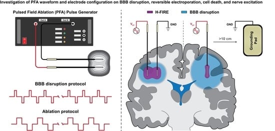
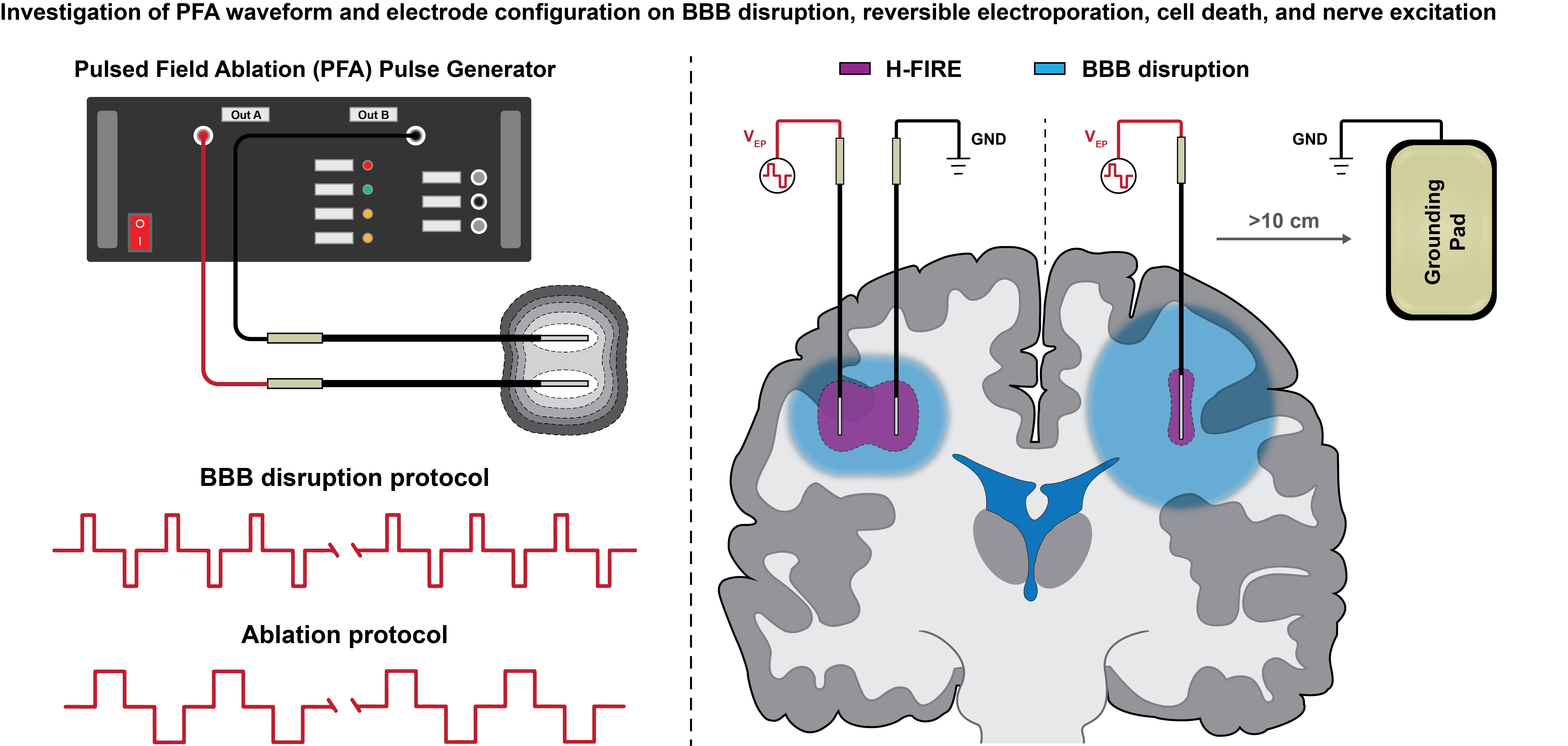
2.1. Study Overview
2.2. Quantifying HF-PEF-Mediated BBB Disruption in Healthy Rodent Brain In Vivo
2.3. Characterization of Healthy Rodent Astrocyte Cell Death and Reversible Electroporation In Vitro
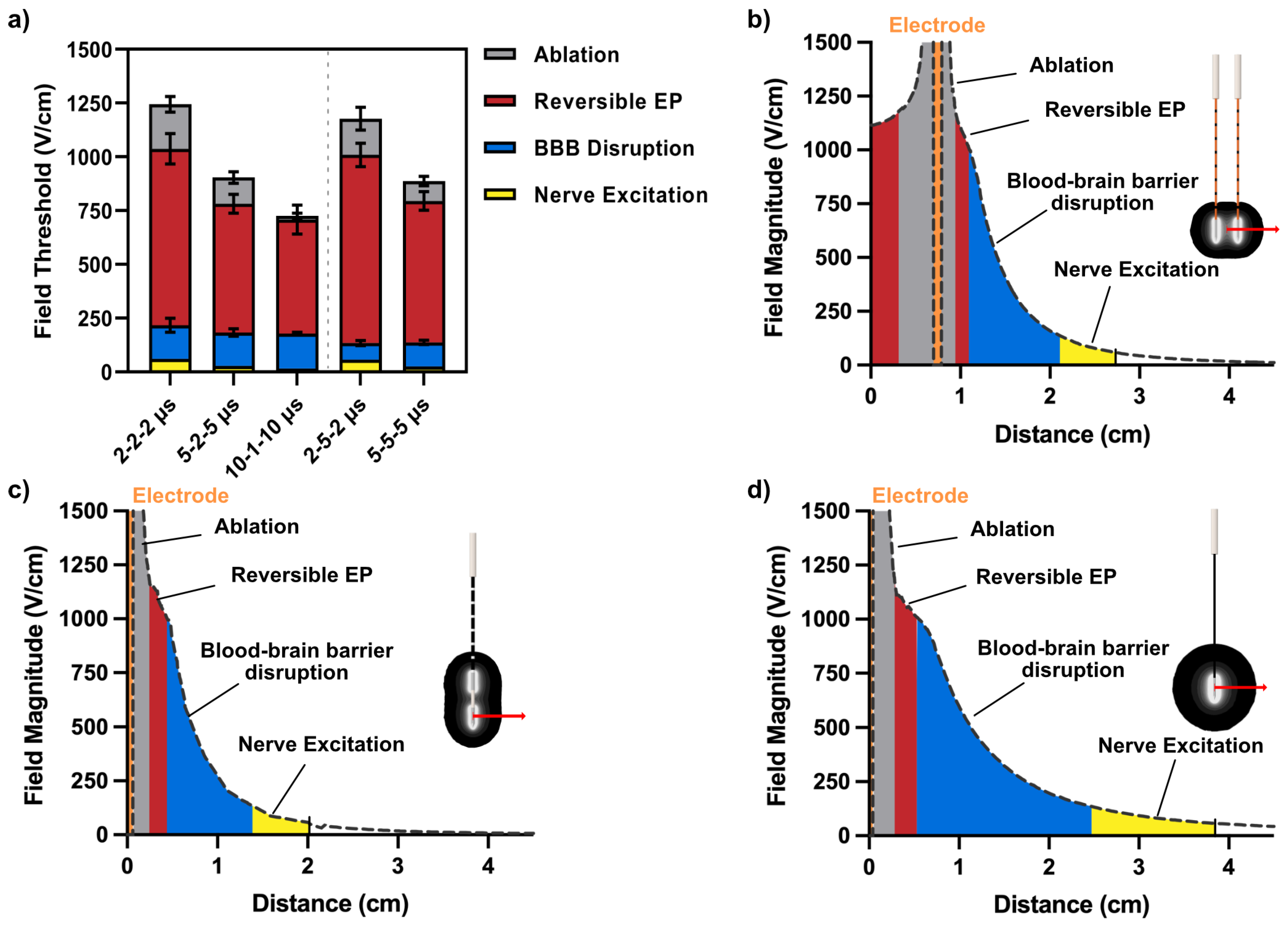
2.4. Electric Field Thresholds for BBB Disruption, Electroporation, Cell Death, and Nerve Excitation
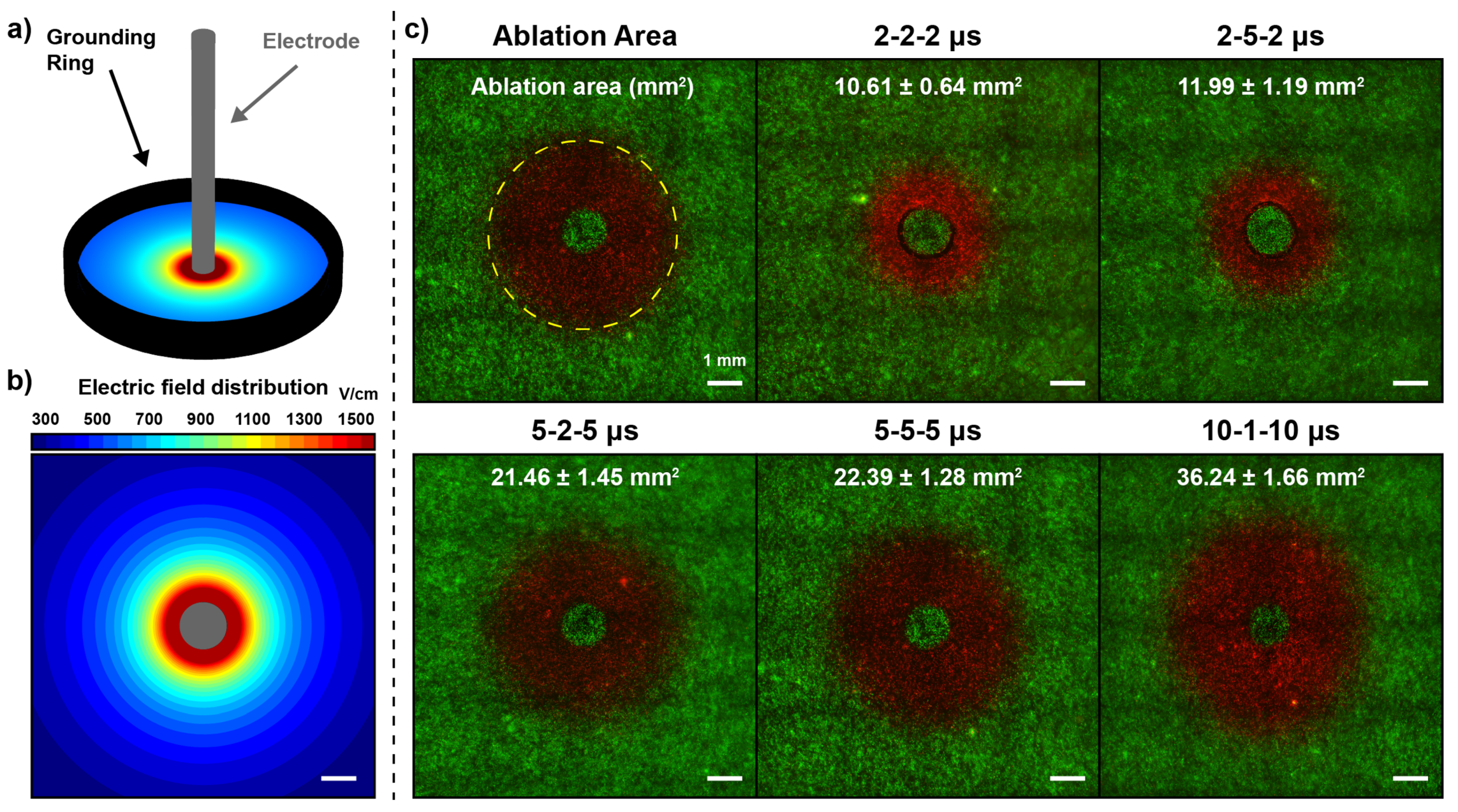
2.4.1. Pulse Width and Interphase Delay Influence the Ablation Electric Field Thresholds
2.4.2. Pulse Width Has a Large Influence on the Reversible Electroporation Field Thresholds
2.4.3. Interphase Delay Has a High Influence on the BBB Disruption Field Thresholds
2.5. HF-PEF Waveform Modulates Extent of Cell Death While Maintaining Large BBB Disruption
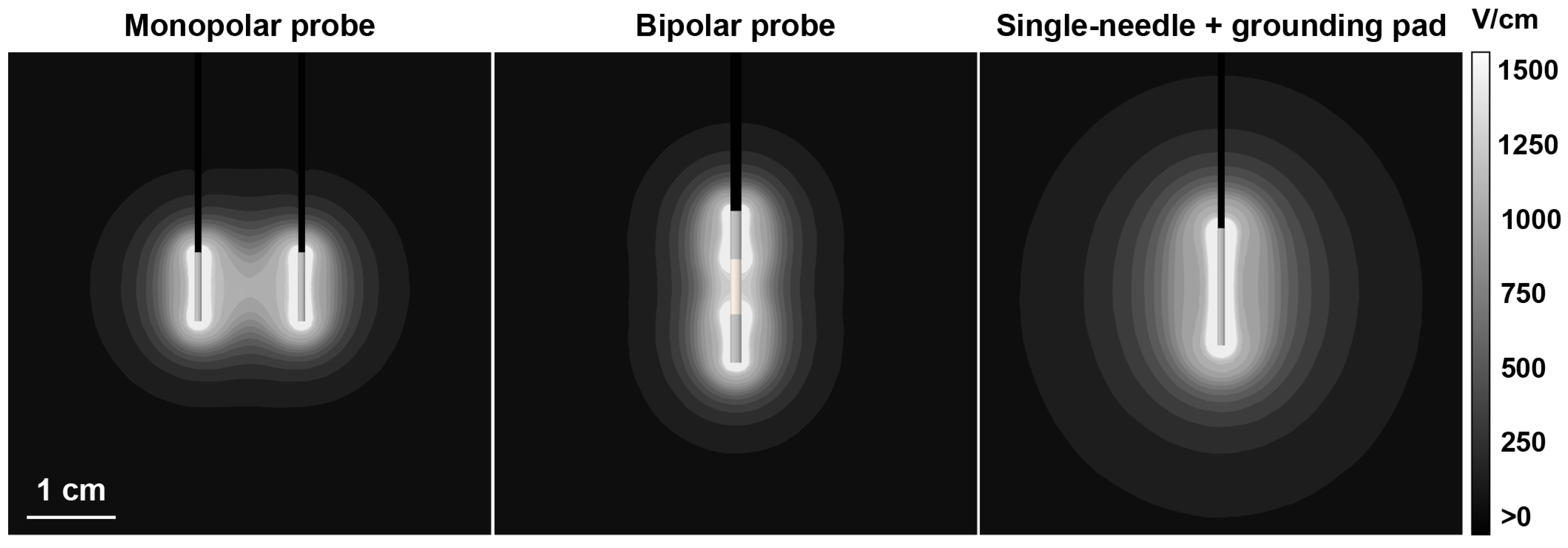
2.5.1. Differences in Field Gradients between Electrode Types Can Be Exploited to Modulate Extent of Electroporation Effects and BBB Disruption
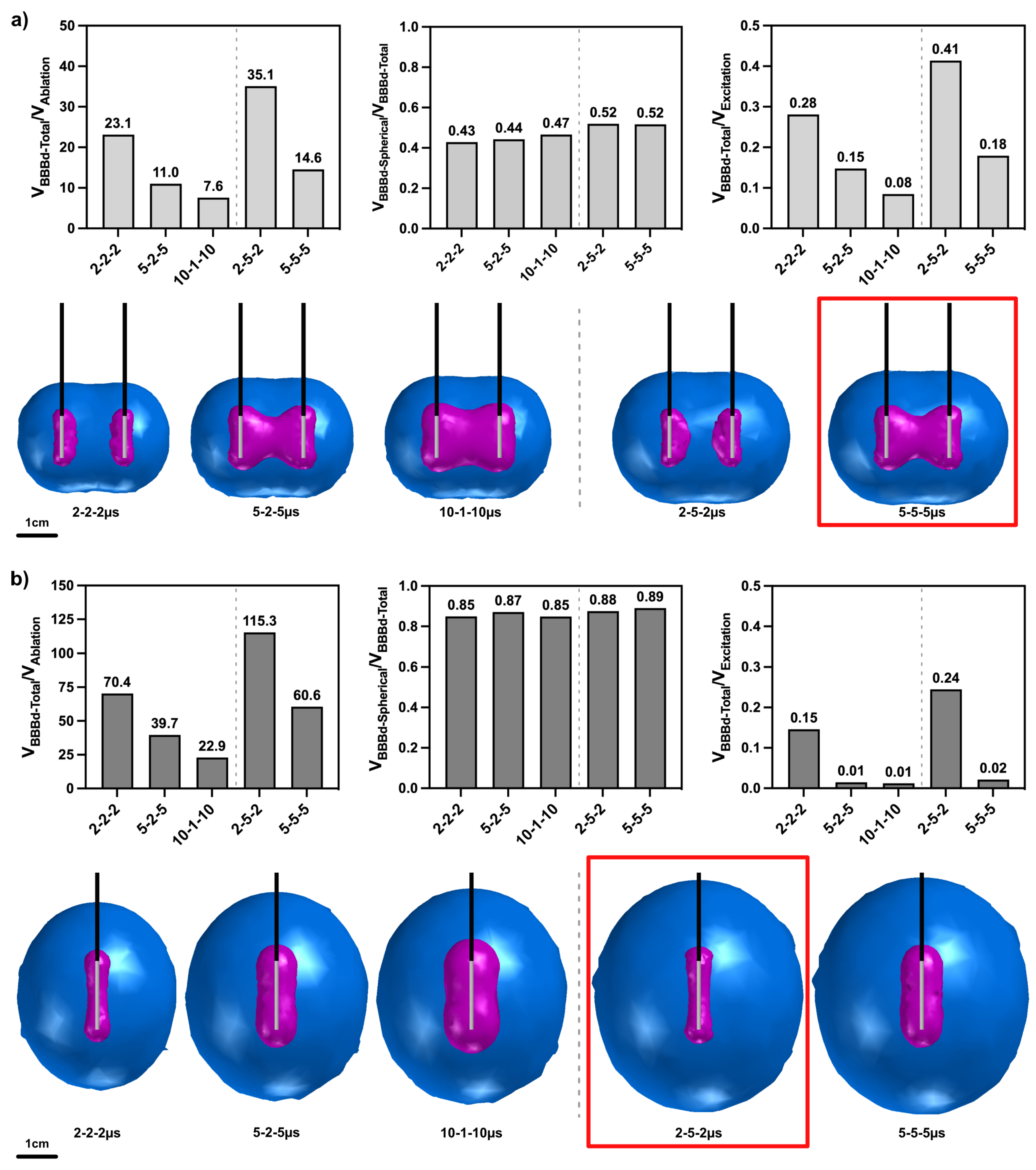
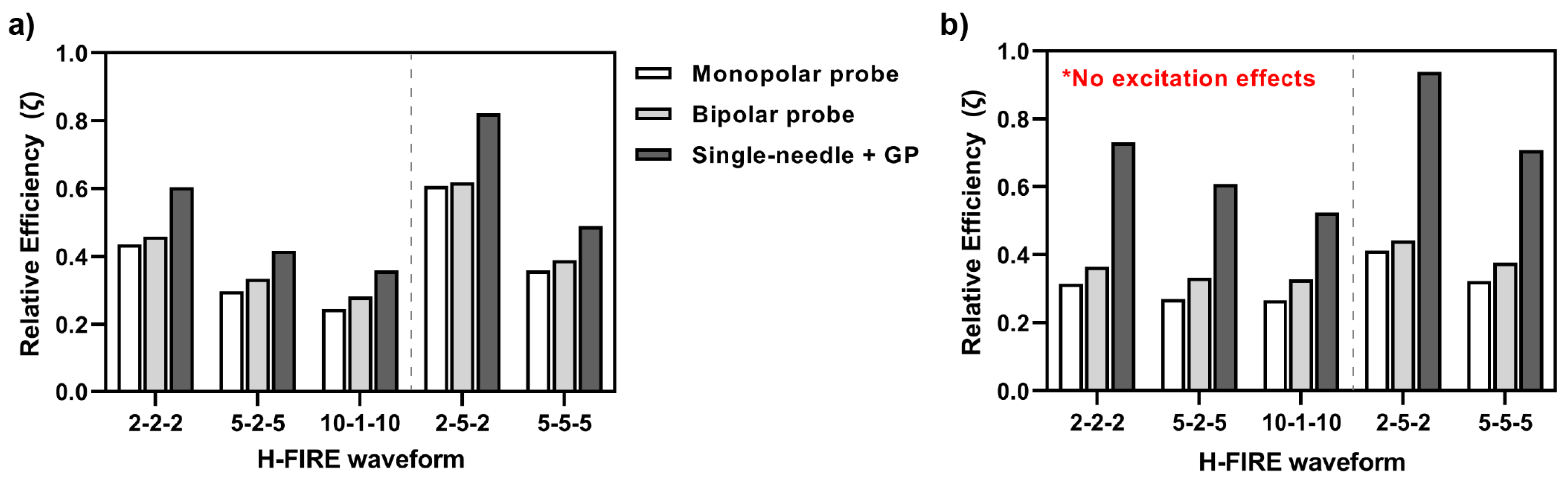
2.5.2. HF-PEF Waveforms Selectively Modulate the Extent of Electroporation Effects, BBB Disruption, and Nerve Excitation
3. Discussion
4. Materials and Methods
4.1. Surgical Procedures and Assurances
4.2. High-Frequency Pulsed Electric Fields and Parameter Selection for In Vivo Studies
4.3. MR Imaging and Gross Pathology for In Vivo BBB Disruption Volumetrics
4.4. Cell Culture and Determination of H-FIRE Ablation Electric Field Thresholds
4.5. Numerical Determination of BBBd, Ablation, Electroporation, and Nerve Excitation Thresholds
4.6. Numerical Methods for Elucidating the Effects of HF-PEF Waveforms on BBB Disruption, Cell Ablation, Electroporation, and Nerve Excitation
4.7. Statistical Analysis
5. Conclusions
6. Patents
Supplementary Materials
Author Contributions
Funding
Institutional Review Board Statement
Informed Consent Statement
Data Availability Statement
Acknowledgments
Conflicts of Interest
References
- Gabathuler, R. Approaches to transport therapeutic drugs across the blood-brain barrier to treat brain diseases. Neurobiol. Dis. 2010, 37, 48–57. [Google Scholar] [CrossRef]
- Banks, W.A. From blood-brain barrier to blood-brain interface: New opportunities for CNS drug delivery. Nat. Rev. Drug Discov. 2016, 15, 275–292. [Google Scholar] [CrossRef]
- Abbott, N.J.; Patabendige, A.A.; Dolman, D.E.; Yusof, S.R.; Begley, D.J. Structure and function of the blood-brain barrier. Neurobiol. Dis. 2010, 37, 13–25. [Google Scholar] [CrossRef] [PubMed]
- Iversen, L.; Iversen, S.; Dunnett, S.; Bjorklund, A. Dopamine Handbook; Oxford University Press: Oxford, UK, 2009. [Google Scholar]
- Pardridge, W.M. Alzheimer’s disease drug development and the problem of the blood-brain barrier. Alzheimer’s Dement. 2009, 5, 427–432. [Google Scholar] [CrossRef] [PubMed]
- Gernert, M.; Feja, M. Bypassing the Blood-Brain Barrier: Direct Intracranial Drug Delivery in Epilepsies. Pharmaceutics 2020, 12, 1134. [Google Scholar] [CrossRef]
- Bien-Ly, N.; Boswell, C.A.; Jeet, S.; Beach, T.G.; Hoyte, K.; Luk, W.; Shihadeh, V.; Ulufatu, S.; Foreman, O.; Lu, Y.; et al. Lack of widespread BBB disruption in Alzheimer’s disease models: Focus on therapeutic antibodies. Neuron 2015, 88, 289–297. [Google Scholar] [CrossRef]
- Desai, B.S.; Monahan, A.J.; Carvey, P.M.; Hendey, B. Blood–brain barrier pathology in Alzheimer’s and Parkinson’s disease: Implications for drug therapy. Cell Transplant. 2007, 16, 285–299. [Google Scholar] [CrossRef] [PubMed]
- Bhowmik, A.; Khan, R.; Ghosh, M.K. Blood brain barrier: A challenge for effectual therapy of brain tumors. BioMed Res. Int. 2015, 2015, 320941. [Google Scholar] [CrossRef]
- Lonser, R.R.; Sarntinoranont, M.; Morrison, P.F.; Oldfield, E.H. Convection-enhanced delivery to the central nervous system. J. Neurosurg. 2015, 122, 697–706. [Google Scholar] [CrossRef]
- Rossmeisl, J.H.; Herpai, D.; Quigley, M.; Cecere, T.E.; Robertson, J.L.; D’Agostino, R.B.; Hinckley, J.; Tatter, S.B.; Dickinson, P.J.; Debinski, W. Phase I trial of convection-enhanced delivery of IL13RA2 and EPHA2 receptor targeted cytotoxins in dogs with spontaneous intracranial gliomas. Neuro-Oncology 2021, 23, 422–434. [Google Scholar] [CrossRef] [PubMed]
- Bernal, G.M.; LaRiviere, M.J.; Mansour, N.; Pytel, P.; Cahill, K.E.; Voce, D.J.; Kang, S.; Spretz, R.; Welp, U.; Noriega, S.E.; et al. Convection-enhanced delivery and in vivo imaging of polymeric nanoparticles for the treatment of malignant glioma. Nanomed. Nanotechnol. Biol. Med. 2014, 10, 149–157. [Google Scholar] [CrossRef] [PubMed]
- Patel, S.J.; Shapiro, W.R.; Laske, D.W.; Jensen, R.L.; Asher, A.L.; Wessels, B.W.; Carpenter, S.P.; Shan, J.S. Safety and feasibility of convection-enhanced delivery of Cotara for the treatment of malignant glioma: Initial experience in 51 patients. Neurosurgery 2005, 56, 1243–1253. [Google Scholar] [CrossRef] [PubMed]
- Kunwar, S.; Chang, S.; Westphal, M.; Vogelbaum, M.; Sampson, J.; Barnett, G.; Shaffrey, M.; Ram, Z.; Piepmeier, J.; Prados, M.; et al. Phase III randomized trial of CED of IL13-PE38QQR vs. Gliadel wafers for recurrent glioblastoma. Neuro-Oncology 2010, 12, 871–881. [Google Scholar] [CrossRef]
- Sheikov, N.; McDannold, N.; Sharma, S.; Hynynen, K. Effect of focused ultrasound applied with an ultrasound contrast agent on the tight junctional integrity of the brain microvascular endothelium. Ultrasound Med. Biol. 2008, 34, 1093–1104. [Google Scholar] [CrossRef] [PubMed]
- Aryal, M.; Arvanitis, C.D.; Alexander, P.M.; McDannold, N. Ultrasound-mediated blood-brain barrier disruption for targeted drug delivery in the central nervous system. Adv. Drug Deliv. Rev. 2014, 72, 94–109. [Google Scholar] [CrossRef]
- Hjouj, M.; Last, D.; Guez, D.; Daniels, D.; Sharabi, S.; Lavee, J.; Rubinsky, B.; Mardor, Y. MRI study on reversible and irreversible electroporation induced blood brain barrier disruption. PLoS ONE 2012, 7, e42817. [Google Scholar] [CrossRef]
- Lorenzo, M.F.; Thomas, S.C.; Kani, Y.; Hinckley, J.; Lee, M.; Adler, J.; Verbridge, S.S.; Hsu, F.C.; Robertson, J.L.; Davalos, R.V.; et al. Temporal characterization of blood-brain barrier disruption with high-frequency electroporation. Cancers 2019, 11, 1850. [Google Scholar] [CrossRef] [PubMed]
- Fang, Z.; Chen, L.; Moser, M.A.; Zhang, W.; Qin, Z.; Zhang, B. Electroporation-Based Therapy for Brain Tumors: A Review. J. Biomech. Eng. 2021, 143, 100802. [Google Scholar] [CrossRef]
- Gehl, J. Electroporation: Theory and methods, perspectives for drug delivery, gene therapy and research. Acta Physiol. Scand. 2003, 177, 437–447. [Google Scholar] [CrossRef]
- Wittkampf, F.H.; van Es, R.; Neven, K. Electroporation and its relevance for cardiac catheter ablation. JACC Clin. Electrophysiol. 2018, 4, 977–986. [Google Scholar] [CrossRef]
- Scheffer, H.J.; Stam, A.G.; Geboers, B.; Vroomen, L.G.; Ruarus, A.; de Bruijn, B.; van den Tol, M.P.; Kazemier, G.; Meijerink, M.R.; de Gruijl, T.D. Irreversible electroporation of locally advanced pancreatic cancer transiently alleviates immune suppression and creates a window for antitumor T cell activation. Oncoimmunology 2019, 8, 1652532. [Google Scholar] [CrossRef]
- Zhao, J.; Wen, X.; Tian, L.; Li, T.; Xu, C.; Wen, X.; Melancon, M.P.; Gupta, S.; Shen, B.; Peng, W.; et al. Irreversible electroporation reverses resistance to immune checkpoint blockade in pancreatic cancer. Nat. Commun. 2019, 10, 899. [Google Scholar] [CrossRef]
- Agerholm-Larsen, B.; Iversen, H.K.; Ibsen, P.; Moller, J.M.; Mahmood, F.; Jensen, K.S.; Gehl, J. Preclinical validation of electrochemotherapy as an effective treatment for brain tumors. Cancer Res. 2011, 71, 3753–3762. [Google Scholar] [CrossRef]
- Sharabi, S.; Guez, D.; Daniels, D.; Cooper, I.; Atrakchi, D.; Liraz-Zaltsman, S.; Last, D.; Mardor, Y. The application of point source electroporation and chemotherapy for the treatment of glioma: A randomized controlled rat study. Sci. Rep. 2020, 10, 2178. [Google Scholar]
- Arena, C.B.; Garcia, P.A.; Sano, M.B.; Olson, J.D.; Rogers-Cotrone, T.; Rossmeisl, J.H., Jr.; Davalos, R.V. Focal blood-brain-barrier disruption with high-frequency pulsed electric fields. Technology 2014, 2, 206–213. [Google Scholar] [CrossRef]
- Chen, Y.; Moser, M.A.; Luo, Y.; Zhang, W.; Zhang, B. Chemical enhancement of irreversible electroporation: A review and future suggestions. Technol. Cancer Res. Treat. 2019, 18, 1533033819874128. [Google Scholar] [CrossRef]
- Latouche, E.L.; Arena, C.B.; Ivey, J.W.; Garcia, P.A.; Pancotto, T.E.; Pavlisko, N.; Verbridge, S.S.; Davalos, R.V.; Rossmeisl, J.H. High-frequency irreversible electroporation for intracranial meningioma: A feasibility study in a spontaneous canine tumor model. Technol. Cancer Res. Treat. 2018, 17, 1533033818785285. [Google Scholar] [CrossRef]
- Aycock, K.N.; Zhao, Y.; Lorenzo, M.F.; Davalos, R.V. A theoretical argument for extended interpulse delays in therapeutic high-frequency irreversible electroporation treatments. IEEE Trans. Biomed. Eng. 2021, 68, 1999–2010. [Google Scholar] [CrossRef]
- Miklavčič, D.; Pucihar, G.; Pavlovec, M.; Ribarič, S.; Mali, M.; Maček-Lebar, A.; Petkovšek, M.; Nastran, J.; Kranjc, S.; Čemažar, M.; et al. The effect of high frequency electric pulses on muscle contractions and antitumor efficiency in vivo for a potential use in clinical electrochemotherapy. Bioelectrochemistry 2005, 65, 121–128. [Google Scholar] [CrossRef] [PubMed]
- Arena, C.B.; Sano, M.B.; Rossmeisl, J.H.; Caldwell, J.L.; Garcia, P.A.; Rylander, M.N.; Davalos, R.V. High-frequency irreversible electroporation (H-FIRE) for non-thermal ablation without muscle contraction. Biomed. Eng. Online 2011, 10, 102. [Google Scholar] [CrossRef] [PubMed]
- van Es, R.; Konings, M.K.; Du Pré, B.C.; Neven, K.; van Wessel, H.; van Driel, V.J.; Westra, A.H.; Doevendans, P.A.; Wittkampf, F.H. High-frequency irreversible electroporation for cardiac ablation using an asymmetrical waveform. Biomed. Eng. Online 2019, 18, 75. [Google Scholar] [CrossRef]
- Vižintin, A.; Vidmar, J.; Ščančar, J.; Miklavčič, D. Effect of interphase and interpulse delay in high-frequency irreversible electroporation pulses on cell survival, membrane permeabilization and electrode material release. Bioelectrochemistry 2020, 134, 107523. [Google Scholar] [CrossRef]
- Klein, N.; Guenther, E.; Mikus, P.; Stehling, M.K.; Rubinsky, B. Single exponential decay waveform; A synergistic combination of electroporation and electrolysis (E2) for tissue ablation. PeerJ 2017, 5, e3190. [Google Scholar] [CrossRef]
- Pakhomov, A.G.; Semenov, I.; Xiao, S.; Pakhomova, O.N.; Gregory, B.; Schoenbach, K.H.; Ullery, J.C.; Beier, H.T.; Rajulapati, S.R.; Ibey, B.L. Cancellation of cellular responses to nanoelectroporation by reversing the stimulus polarity. Cell. Mol. Life Sci. 2014, 71, 4431–4441. [Google Scholar] [CrossRef]
- Sharabi, S.; Last, D.; Daniels, D.; Zaltsman, S.L.; Mardor, Y. The effects of point-source electroporation on the blood-brain barrier and brain vasculature in rats: An MRI and histology study. Bioelectrochemistry 2020, 134, 107521. [Google Scholar] [CrossRef] [PubMed]
- McNeal, D.R. Analysis of a model for excitation of myelinated nerve. IEEE Trans. Biomed. Eng. 1976, BME-23, 329–337. [Google Scholar] [CrossRef] [PubMed]
- Wasson, E.M.; Alinezhadbalalami, N.; Brock, R.M.; Allen, I.C.; Verbridge, S.S.; Davalos, R.V. Understanding the role of calcium-mediated cell death in high-frequency irreversible electroporation. Bioelectrochemistry 2020, 131, 107369. [Google Scholar] [CrossRef] [PubMed]
- Yamada, K.M.; Cukierman, E. Modeling tissue morphogenesis and cancer in 3D. Cell 2007, 130, 601–610. [Google Scholar] [CrossRef]
- Kim, J.B. Three-dimensional tissue culture models in cancer biology. In Seminars in Cancer Biology; Elsevier: Amsterdam, The Netherlands, 2005; Volume 15, pp. 365–377. [Google Scholar]
- Pirc, E.; Reberšek, M.; Miklavčič, D. Functional Requirements and Quality Assurance Necessary for Successful Incorporation of Electroporation-Based Therapies Into Clinical Practice. J. Med. Devices 2020, 14. [Google Scholar] [CrossRef]
- Ding, G.R.; Qiu, L.B.; Wang, X.W.; Li, K.C.; Zhou, Y.C.; Zhou, Y.; Zhang, J.; Zhou, J.X.; Li, Y.R.; Guo, G.Z. EMP-induced alterations of tight junction protein expression and disruption of the blood-brain barrier. Toxicol. Lett. 2010, 196, 154–160. [Google Scholar] [CrossRef]
- Miklavcic, D.; Novickij, V.; Kranjc, M.; Polajzer, T.; Meglic, S.H.; Napotnik, T.B.; Lisjak, D. Contactless electroporation induced by high intensity pulsed electromagnetic fields via distributed nanoelectrodes. Bioelectrochemistry 2020, 132, 107440. [Google Scholar] [CrossRef]
- Tabatabaei, S.N.; Duchemin, S.; Girouard, H.; Martel, S. Towards MR-navigable nanorobotic carriers for drug delivery into the brain. In Proceedings of the 2012 IEEE International Conference on Robotics and Automation, Saint Paul, MN, USA, 14–18 May 2012; pp. 727–732. [Google Scholar]
- Uyama, O.; Okamura, N.; Yanase, M.; Narita, M.; Kawabata, K.; Sugita, M. Quantitative evaluation of vascular permeability in the gerbil brain after transient ischemia using Evans blue fluorescence. J. Cereb. Blood Flow Metab. 1988, 8, 282–284. [Google Scholar] [CrossRef] [PubMed]
- Hasgall, P.; Di Gennaro, F.; Baumgartner, C.; Neufeld, E.; Lloyd, B.; Gosselin, M.; Payne, D.; Klingenböck, A.; Kuster, N. IT’IS Database for Thermal and Electromagnetic Parameters of Biological Tissues, Version 4.0. IT’IS. 2018. Available online: https://itis.swiss/virtual-population/tissue-properties/downloads/database-v4-0/ (accessed on 3 September 2021). [CrossRef]
- Voyer, D.; Silve, A.; Mir, L.M.; Scorretti, R.; Poignard, C. Dynamical modeling of tissue electroporation. Bioelectrochemistry 2018, 119, 98–110. [Google Scholar] [CrossRef] [PubMed]
- Zhao, Y.; Bhonsle, S.; Dong, S.; Lv, Y.; Liu, H.; Safaai-Jazi, A.; Davalos, R.V.; Yao, C. Characterization of conductivity changes during high-frequency irreversible electroporation for treatment planning. IEEE Trans. Biomed. Eng. 2017, 65, 1810–1819. [Google Scholar] [CrossRef] [PubMed]
- Gabriel, S.; Lau, R.; Gabriel, C. The dielectric properties of biological tissues: II. Measurements in the frequency range 10 Hz to 20 GHz. Phys. Med. Biol. 1996, 41, 2251. [Google Scholar] [CrossRef]
- Ivorra, A. Bioimpedance monitoring for physicians: An overview. Cent. Nac. Microelectròn. Biomed. Appl. Group 2003, 11, 17. [Google Scholar]
- Sel, D.; Cukjati, D.; Batiuskaite, D.; Slivnik, T.; Mir, L.M.; Miklavcic, D. Sequential finite element model of tissue electropermeabilization. IEEE Trans. Biomed. Eng. 2005, 52, 816–827. [Google Scholar] [CrossRef] [PubMed]
- Miklavčič, D.; Šemrov, D.; Mekid, H.; Mir, L.M. A validated model of in vivo electric field distribution in tissues for electrochemotherapy and for DNA electrotransfer for gene therapy. Biochim. Biophys. Acta Gen. Subj. 2000, 1523, 73–83. [Google Scholar] [CrossRef]
- Holland, M.M.; Bhutiani, N.; Kruse, E.J.; Weiss, M.J.; Christein, J.D.; White, R.R.; Huang, K.W.; Martin, R.C., II. A prospective, multi-institution assessment of irreversible electroporation for treatment of locally advanced pancreatic adenocarcinoma: Initial outcomes from the AHPBA pancreatic registry. HPB 2019, 21, 1024–1031. [Google Scholar] [CrossRef]
- Hosein, P.J.; Echenique, A.; Loaiza-Bonilla, A.; Froud, T.; Barbery, K.; Lima, C.M.R.; Yrizarry, J.M.; Narayanan, G. Percutaneous irreversible electroporation for the treatment of colorectal cancer liver metastases with a proposal for a new response evaluation system. J. Vasc. Interv. Radiol. 2014, 25, 1233–1239. [Google Scholar] [CrossRef]
- DeWitt, M.R.; Latouche, E.L.; Kaufman, J.D.; Fesmire, C.C.; Swet, J.H.; Kirks, R.C.; Baker, E.H.; Vrochides, D.; Iannitti, D.A.; McKillop, I.H.; et al. Simplified non-thermal tissue ablation with a single insertion device enabled by bipolar high-frequency pulses. IEEE Trans. Biomed. Eng. 2019, 67, 2043–2051. [Google Scholar] [CrossRef] [PubMed]


| Waveform | Pathological BBBd (mm3) | MRI BBBd (mm3) | Cerebral (EBD) (g/g) | Serum (EBD) (g/g) |
|---|---|---|---|---|
| Sham | 0.0 ± 0.0 | 0.0 ± 0.0 | 0.2 ± 0.0 | 1494.0 ± 0.0 |
| 2-2-2 s | 36.6 ± 9.4 | 36.7 ± 13.0 | 14.1 ± 0.2 | 1532.8 ± 137.5 |
| 5-2-5 s | 53.9 ± 8.1 | 59.2 ± 10.8 | 15.2 ± 0.1 | 1363.3 ± 152.4 |
| 10-1-10 s | 61.0 ± 2.8 | 60.0 ± 4.2 | N/A | N/A |
| 2-5-2 s | 74.1 ± 7.8 ** | 74.7 ± 9.8 * | 16.9 ± 0.1 | 1326.0 ± 24.7 |
| 5-5-5 s | 81.2 ± 8.0 ** | 84.1 ± 8.7 ** | 18.5 ± 0.3 * | 1318.3 ± 66.8 |
| Waveform | Pathological BBBd (mm3) | BBB Disruption Threshold (V/cm) |
|---|---|---|
| 2-2-2 s (n = 4) | 36.6 ± 9.4 | 216.5 ± 32.7 |
| 5-2-5 s (n = 4) | 53.9 ± 8.1 | 183.0 ± 18.0 |
| 10-1-10 s (n = 2) | 61.0 ± 2.8 | 178.0 ± 6.0 |
| 2-5-2 s (n = 4) | 74.1 ± 7.8 | 133.8 ± 11.4 |
| 5-5-5 s (n = 4) | 81.2 ± 8.0 | 136.3 ± 10.0 |
| Waveform | Reversible Electroporation Area (mm2) | Electroporation Threshold (V/cm) |
| 2-2-2 s (n = 9) | 13.8 ± 2.5 | 1037.0 ± 71.1 |
| 5-2-5 s (n = 8) | 28.3 ± 4.0 | 781.9 ± 44.3 |
| 10-1-10 s (n = 9) | 37.7 ± 10.0 | 708.1 ± 67.3 |
| 2-5-2 s (n = 9) | 14.7 ± 2.1 | 1009.0 ± 54.7 |
| 5-5-5 s (n = 10) | 27.2 ± 4.1 | 795.0 ± 43.4 |
| Waveform | H-FIRE Ablation Area (mm2) | Ablation Threshold (V/cm) |
| 2-2-2 s (n = 8) | 10.6 ± 0.6 | 1244.8 ± 36.2 |
| 5-2-5 s (n = 8) | 21.5 ± 1.5 | 904.2 ± 27.0 |
| 10-1-10 s (n = 9) | 36.2 ± 1.7 | 725.1 ± 12.7 |
| 2-5-2 s (n = 8) | 12.0 ± 1.2 | 1177.4 ± 53.2 |
| 5-5-5 s (n = 9) | 22.4 ± 1.3 | 887.4 ± 21.7 |
| Material | Parameter | Value | Units |
|---|---|---|---|
| Brain tissue | Density, Specific heat, cp Thermal conductivity, k Blood perfusion coefficient, Temperature coefficient, | 1045 3696 0.55 2 | kg/m3 J/(kg·K) W/(m·K) 1/s %/°C |
| Insulation | Density, Specific heat, cp Thermal conductivity, k Electrical conductivity, | 1190 1470 0.18 | kg/m3 J/(kg·K) W/(m·K) S/m |
| Stainless steel | Density, Specific heat, cp Thermal conductivity, k Electrical conductivity, | 7850 475 44.5 | kg/m3 J/(kg·K) W/(m·K) S/m |
| Waveform (s) | Char. Frequency (kHz) | Conductivity 0 (S/m) | Edelta (V/cm) | A (Unitless) |
|---|---|---|---|---|
| 10-1-10 | 45.5 | 0.1267 | 725.1 | 1.302 |
| 5-5-5 | 50 | 0.1275 | 887.4 | 1.288 |
| 5-2-5 | 71.4 | 0.1306 | 904.2 | 1.234 |
| 2-5-2 | 71.4 | 0.1306 | 1177.4 | 1.234 |
| 2-2-2 | 125 | 0.1358 | 1244.8 | 1.148 |
Publisher’s Note: MDPI stays neutral with regard to jurisdictional claims in published maps and institutional affiliations. |
© 2021 by the authors. Licensee MDPI, Basel, Switzerland. This article is an open access article distributed under the terms and conditions of the Creative Commons Attribution (CC BY) license (https://creativecommons.org/licenses/by/4.0/).
Share and Cite
Lorenzo, M.F.; Campelo, S.N.; Arroyo, J.P.; Aycock, K.N.; Hinckley, J.; Arena, C.B.; Rossmeisl, J.H., Jr.; Davalos, R.V. An Investigation for Large Volume, Focal Blood-Brain Barrier Disruption with High-Frequency Pulsed Electric Fields. Pharmaceuticals 2021, 14, 1333. https://0-doi-org.brum.beds.ac.uk/10.3390/ph14121333
Lorenzo MF, Campelo SN, Arroyo JP, Aycock KN, Hinckley J, Arena CB, Rossmeisl JH Jr., Davalos RV. An Investigation for Large Volume, Focal Blood-Brain Barrier Disruption with High-Frequency Pulsed Electric Fields. Pharmaceuticals. 2021; 14(12):1333. https://0-doi-org.brum.beds.ac.uk/10.3390/ph14121333
Chicago/Turabian StyleLorenzo, Melvin F., Sabrina N. Campelo, Julio P. Arroyo, Kenneth N. Aycock, Jonathan Hinckley, Christopher B. Arena, John H. Rossmeisl, Jr., and Rafael V. Davalos. 2021. "An Investigation for Large Volume, Focal Blood-Brain Barrier Disruption with High-Frequency Pulsed Electric Fields" Pharmaceuticals 14, no. 12: 1333. https://0-doi-org.brum.beds.ac.uk/10.3390/ph14121333