
Accuracy and Reliability of Software Navigation for Acetabular Component Placement in THA: An In Vitro Validation Study


Abstract
:1. Introduction
2. Materials and Methods
2.1. Experimental Setup
2.2. Experimental Design
2.3. 3D Analysis
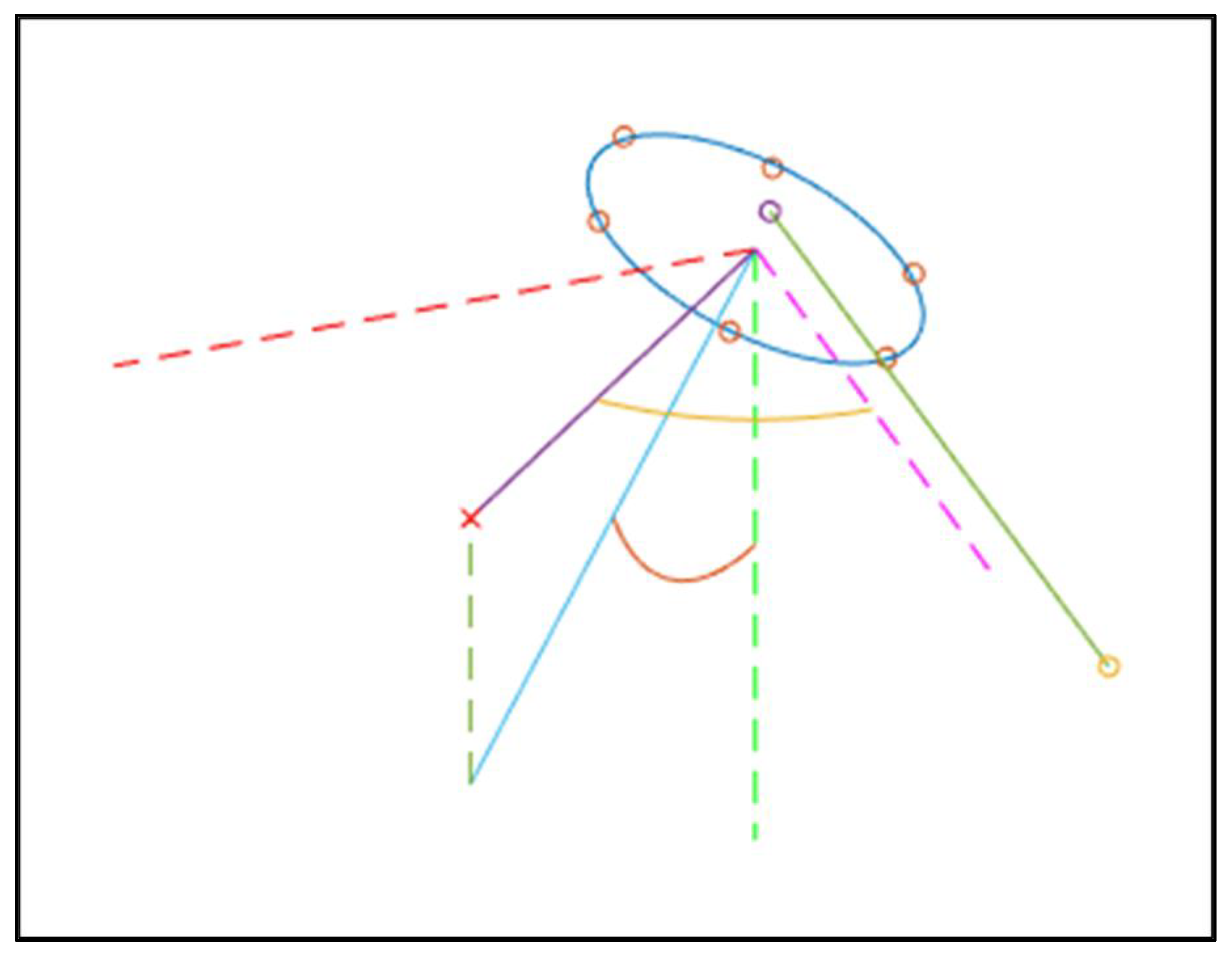
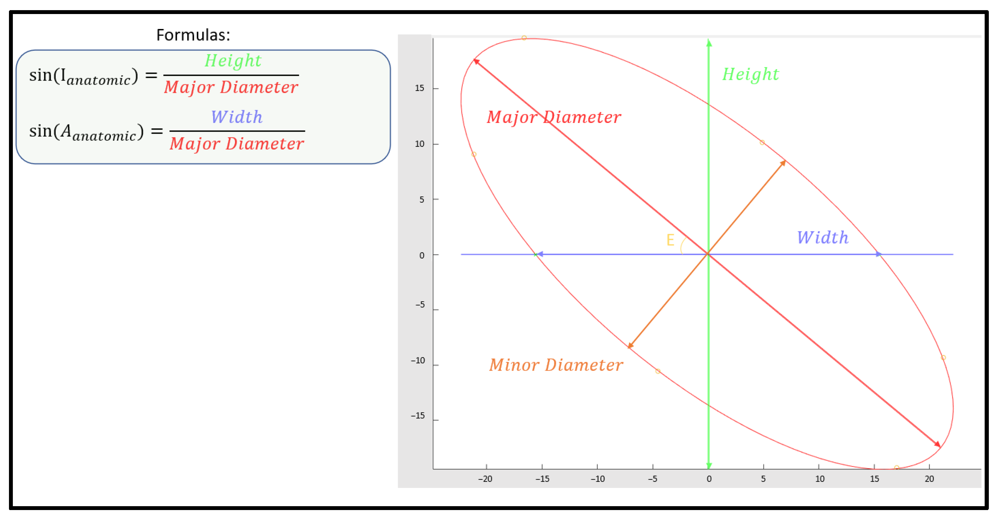
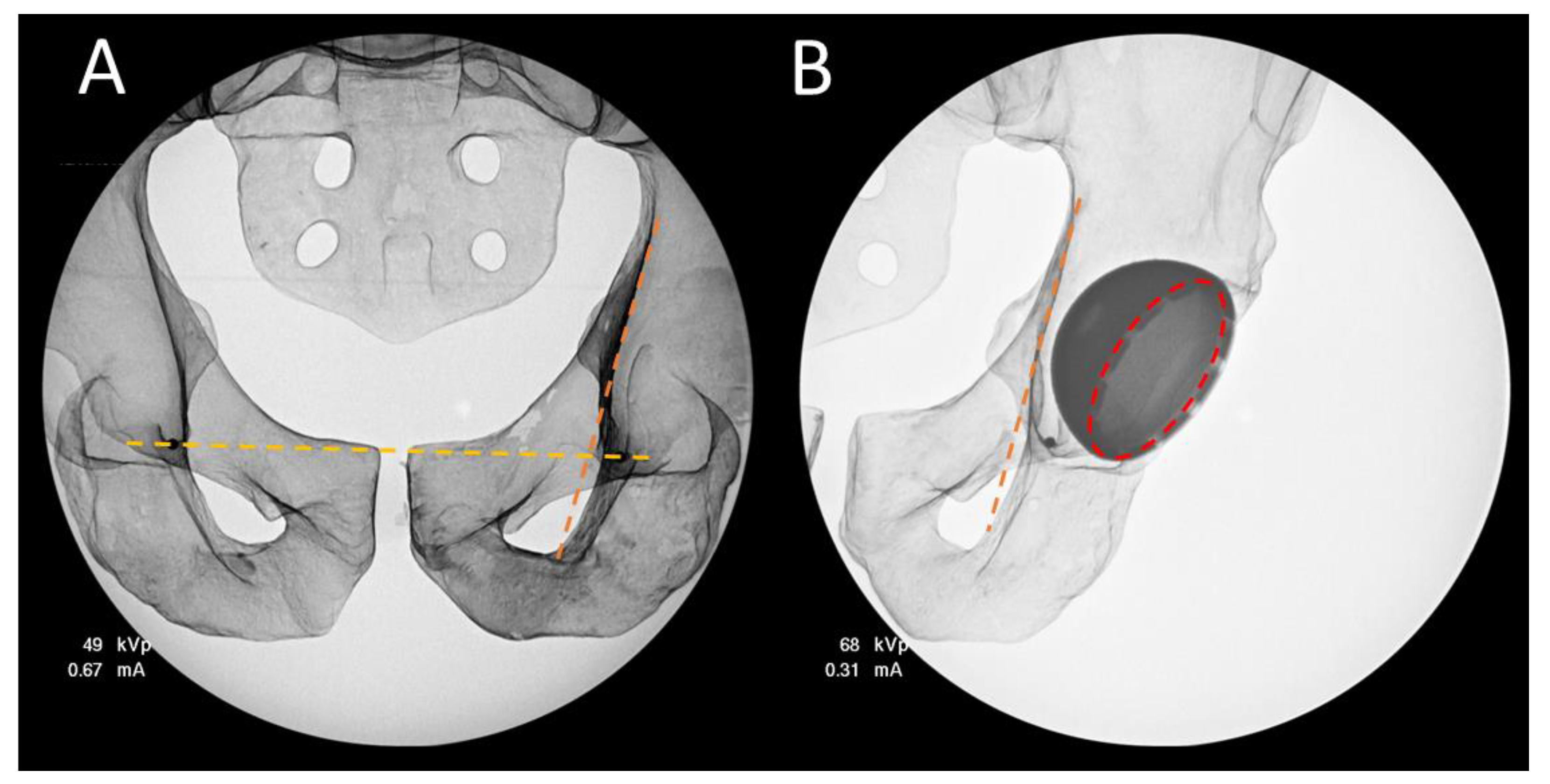
2.4. 2D Analysis
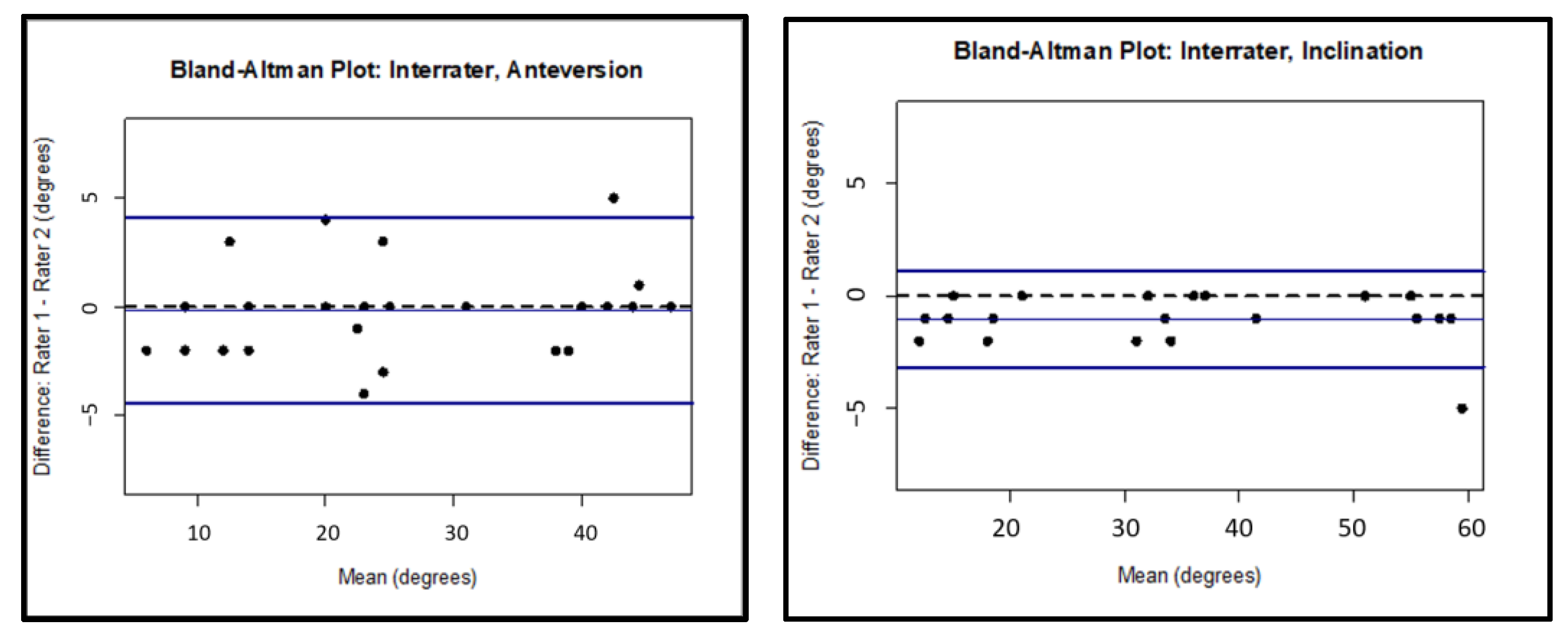
2.5. Statistical Analysis
3. Results
4. Discussion
5. Conclusions
Author Contributions
Funding
Data Availability Statement
Acknowledgments
Conflicts of Interest
References
- Wera, G.D.; Ting, N.T.; Moric, M.; Paprosky, W.G.; Sporer, S.M.; Della Valle, C.J. Classification and Management of the Unstable Total Hip Arthroplasty. J. Arthroplast. 2012, 27, 710–715. [Google Scholar] [CrossRef] [PubMed]
- Higa, M.; Tanino, H.; Abo, M.; Kakunai, S.; Banks, S.A. Effect of acetabular component anteversion on dislocation mechanisms in total hip arthroplasty. J. Biomech. 2011, 44, 1810–1813. [Google Scholar] [CrossRef] [PubMed]
- Callanan, M.C.; Jarrett, B.; Zurakowski, D.; Rubash, H.E.; Freiberg, A.A.; Malchau, H. The john charnley award: Risk factors for cup malpositioning: Quality improvement through a joint registry at a tertiary hospital. Clin. Orthop. Relat. Res. 2011, 469, 319–329. [Google Scholar] [CrossRef] [PubMed] [Green Version]
- Lewinnek, G.E.; Lewis, J.L.; Tarr, R.; Compere, C.L.; Zimmerman, J.R. Dislocations after total hip-replacement arthroplasties. J. Bone Jt. Surg. Am. 1978, 60, 217–220. [Google Scholar] [CrossRef]
- Jolles, B.M.; Zangger, P.; Leyvraz, P.F. Factors predisposing to dislocation after primary total hip arthroplasty: A multivariate analysis. J. Arthroplast. 2002, 17, 282–288. [Google Scholar] [CrossRef]
- Rathod, P.A.; Bhalla, S.; Deshmukh, A.J.; Rodriguez, J.A. Does fluoroscopy with anterior hip arthroplasty decrease acetabular cup variability compared with a nonguided posterior approach? Clin. Orthop. Relat. Res. 2014, 472, 1877–1885. [Google Scholar] [CrossRef] [Green Version]
- Delagrammaticas, D.E.; Alvi, H.M.; Kaat, A.J.; Sullivan, R.R.; Stover, M.D.; Manning, D.W. Quantitative Effect of Pelvic Position on Radiographic Assessment of Acetabular Component Position. J. Arthroplast. 2018, 33, 608–614.e1. [Google Scholar] [CrossRef]
- Leenders, T.; Vandevelde, D.; Mahieu, G.; Nuyts, R. Reduction in variability of acetabular cup abduction using computer assisted surgery: A prospective and randomized study. Comput. Aided Surg. 2002, 7, 99–106. [Google Scholar] [CrossRef]
- Abdel, M.P.; von Roth, P.; Jennings, M.T.; Hanssen, A.D.; Pagnano, M.W. What Safe Zone? The Vast Majority of Dislocated THAs Are Within the Lewinnek Safe Zone for Acetabular Component Position. Clin. Orthop. Relat. Res. 2016, 474, 386–391. [Google Scholar] [CrossRef] [Green Version]
- Bozic, K.J.; Ong, K.; Lau, E.; Kurtz, S.M.; Vail, T.P.; Rubash, H.E.; Berry, D.J. Risk of complication and revision total hip arthroplasty among medicare patients with different bearing surfaces. Clin. Orthop. Relat. Res. 2010, 468, 2357–2362. [Google Scholar] [CrossRef] [Green Version]
- Jolles, B.M.; Genoud, P.; Hoffmeyer, P. Computer-assisted cup placement techniques in total hip arthroplasty improve accuracy of placement. Clin. Orthop. Relat. Res. 2004, 426, 174–179. [Google Scholar] [CrossRef] [PubMed]
- Haaker, R.G.; Tiedjen, K.; Ottersbach, A.; Rubenthaler, F.; Stockheim, M.; Stiehl, J.B. Comparison of conventional versus computer-navigated acetabular component insertion. J. Arthroplast. 2007, 22, 151–159. [Google Scholar] [CrossRef] [PubMed]
- Dorr, L.D.; Malik, A.; Wan, Z.; Long, W.T.; Harris, M. Precision and bias of imageless computer navigation and surgeon estimates for acetabular component position. Clin. Orthop. Relat. Res. 2007, 465, 92–99. [Google Scholar] [CrossRef] [PubMed]
- Kalteis, T.; Handel, M.; Bäthis, H.; Perlick, L.; Tingart, M.; Grifka, J. Imageless navigation for insertion of the acetabular component in total hip arthroplasty: Is it as accurate as CT-based navigation? J. Bone Jt. Surg. Br. 2006, 88, 163–167. [Google Scholar] [CrossRef] [PubMed]
- Kievit, A.J.; Dobbe, J.G.G.; Mallee, W.H.; Blankevoort, L.; Streekstra, G.J.; Schafroth, M.U. Accuracy of cup placement in total hip arthroplasty by means of a mechanical positioning device: A comprehensive cadaveric 3d analysis of 16 specimens. HIP Int. 2021, 31, 5865. [Google Scholar] [CrossRef]
- Gurgel, H.M.; Croci, A.T.; Cabrita, H.A.; Vicente, J.R.N.; Leonhardt, M.C.; Rodrigues, J.C. Acetabular component positioning in total hip arthroplasty with and without a computer-assisted system: A prospective, randomized, and controlled study. J. Arthroplast. 2014, 29, 167–171. [Google Scholar] [CrossRef]
- Beamer, B.S.; Morgan, J.H.; Barr, C.; Weaver, M.J.; Vrahas, M.S. Does Fluoroscopy Improve Acetabular Component Placement in Total Hip Arthroplasty? Clin. Orthop. Relat. Res. 2014, 472, 3953–3962. [Google Scholar] [CrossRef] [Green Version]
- Ji, W.; Stewart, N. Fluoroscopy assessment during anterior minimally invasive hip replacement is more accurate than with the posterior approach. Int. Orthop. 2016, 40, 21–27. [Google Scholar] [CrossRef]
- Fotouhi, J.; Alexander, C.P.; Unberath, M.; Taylor, G.; Lee, S.C.; Fuerst, B.; Johnson, A.; Osgood, G.; Taylor, R.H.; Khanuja, H.; et al. Plan in 2-D, execute in 3-D: An augmented reality solution for cup placement in total hip arthroplasty. J. Med. Imaging 2018, 5, 021205. [Google Scholar] [CrossRef] [Green Version]
- Donati, F.; Costici, P.F.; De Salvatore, S.; Burrofato, A.; Micciulli, E.; Maiese, A.; Santoro, P.; La Russa, R. A Perspective on Management of Limb Fractures in Obese Children: Is It Time for Dedicated Guidelines? Front. Pediatrics 2020, 8, 207. [Google Scholar] [CrossRef]
- Hirschmann, M.T.; Afifi, F.K.; Helfrich, C.; Wirz, D.; Schwägli, T.; Overhoff, H.M.; Moser, W.; Friederich, N.F. Navigated total hip arthroplasty using a 3-D freehand ultrasound system: Technical note and preliminary results. Orthopedics 2011, 34, e816–e820. [Google Scholar] [CrossRef] [PubMed] [Green Version]
- Siebenrock, K.A.; Kalbermatten, D.F.; Ganz, R. Effect of pelvic tilt on acetabular retroversion: A study of pelves from cadavers. Clin. Orthop. Relat. Res. 2003, 407, 241–248. [Google Scholar] [CrossRef] [PubMed]
- Alvarez, A.M.; Suarez, J.C.; Patel, P.; Benton, E.G. Fluoroscopic imaging of acetabular cup position during THA through a direct anterior approach. Orthopedics 2013, 36, 776–777. [Google Scholar] [CrossRef] [PubMed] [Green Version]
- Slotkin, E.M.; Patel, P.D.; Suarez, J.C. Accuracy of fluoroscopic guided acetabular component positioning during direct anterior total hip arthroplasty. J. Arthroplast. 2015, 30, 102–106. [Google Scholar] [CrossRef] [PubMed]
- Rueckl, K.; Alcaide, D.J.; Springer, B.; Rueckl, S.; Kasparek, M.F.; Boettner, F. Intraoperative measurement of cup inclination using fluoroscopy requires a correction factor. Arch. Orthop. Trauma Surg. 2019, 139, 1511–1517. [Google Scholar] [CrossRef]
- Barrack, R.L.; Krempec, J.A.; Clohisy, J.C.; McDonald, D.J.; Ricci, W.M.; Ruh, E.L.; Nunley, R.M. Accuracy of Acetabular Component Position. J. Bone Jt. Surg. Am. 2013, 95, 1760–1768. [Google Scholar] [CrossRef] [Green Version]
- Murray, D.W. The definition and measurement of acetabular orientation. J. Bone Jt. Surg. Br. 1993, 75, 228–232. [Google Scholar] [CrossRef] [Green Version]
- Duffy, G.P.; Wannomae, K.K.; Rowell, S.L.; Muratoglu, O.K. Fracture of a Cross-Linked Polyethylene Liner Due to Impingement. J. Arthroplast. 2009, 24, 158.e15–158.e19. [Google Scholar] [CrossRef]
- Moskal, J.T.; Capps, S.G. Improving the accuracy of acetabular component orientation: Avoiding malposition. J. Am. Acad. Orthop. Surg. 2010, 18, 286–296. [Google Scholar] [CrossRef]
- Kennedy, J.G.; Rogers, W.B.; Soffe, K.E.; Sullivan, R.J.; Griffen, D.G.; Sheehan, L.J. Effect of acetabular component orientation on recurrent dislocation, pelvic osteolysis, polyethylene wear, and component migration. J. Arthroplast. 1998, 13, 530–534. [Google Scholar] [CrossRef]
- Nishii, T.; Sugano, N.; Miki, H.; Koyama, T.; Takao, M.; Yoshikawa, H. Influence of component positions on dislocation: Computed tomographic evaluations in a consecutive series of total hip arthroplasty. J. Arthroplast. 2004, 19, 162–166. [Google Scholar] [CrossRef] [PubMed]
- Del Schutte, H.J.; Lipman, A.J.; Bannar, S.M.; Livermore, J.T.; Ilstrup, D.; Morrey, B.F. Effects of acetabular abduction on cup wear rates in total hip arthroplasty. J. Arthroplast. 1998, 13, 621–626. [Google Scholar] [CrossRef]
- Archbold, H.A.P.; Slomczykowski, M.; Crone, M.; Eckman, K.; Jaramaz, B.; Beverland, D.E. The relationship of the orientation of the transverse acetabular ligament and acetabular labrum to the suggested safe zones of cup positioning in total hip arthroplasty. HIP Int. 2008, 18, 1–6. [Google Scholar] [CrossRef] [PubMed]
- Hambright, D.; Hellman, M.; Barrack, R. Intra-operative digital imaging: Assuring the alignment of components when undertaking total hip arthroplasty. Bone Jt. J. 2018, 100B, 36–43. [Google Scholar] [CrossRef]
- Ezzet, K.A.; Mccauley, J.C. Use of Intraoperative X-rays to Optimize Component Position and Leg Length During Total Hip Arthroplasty. J. Arthroplast. 2014, 29, 580–585. [Google Scholar] [CrossRef]
- Kurtz, S.; Ong, K.; Lau, E.; Mowat, F.; Halpern, M. Projections of primary and revision hip and knee arthroplasty in the United States from 2005 to 2030. J. Bone Jt. Surg. Am. 2007, 89-A, 780–785. [Google Scholar] [CrossRef]
- Laucis, N.C.; Chowdhury, M.; Dasgupta, A.; Bhattacharyya, T. Trend Toward High-Volume Hospitals and the Influence on Complications in Knee and Hip Arthroplasty. J. Bone Jt. Surg. Am. 2016, 98, 707–712. [Google Scholar] [CrossRef] [Green Version]
- Penenberg, B.L.; Samagh, S.P.; Rajaee, S.S.; Woehnl, A.; Brien, W.W. Digital Radiography in Total Hip Arthroplasty. J. Bone Jt. Surg. Am. 2018, 100, 226–235. [Google Scholar] [CrossRef]


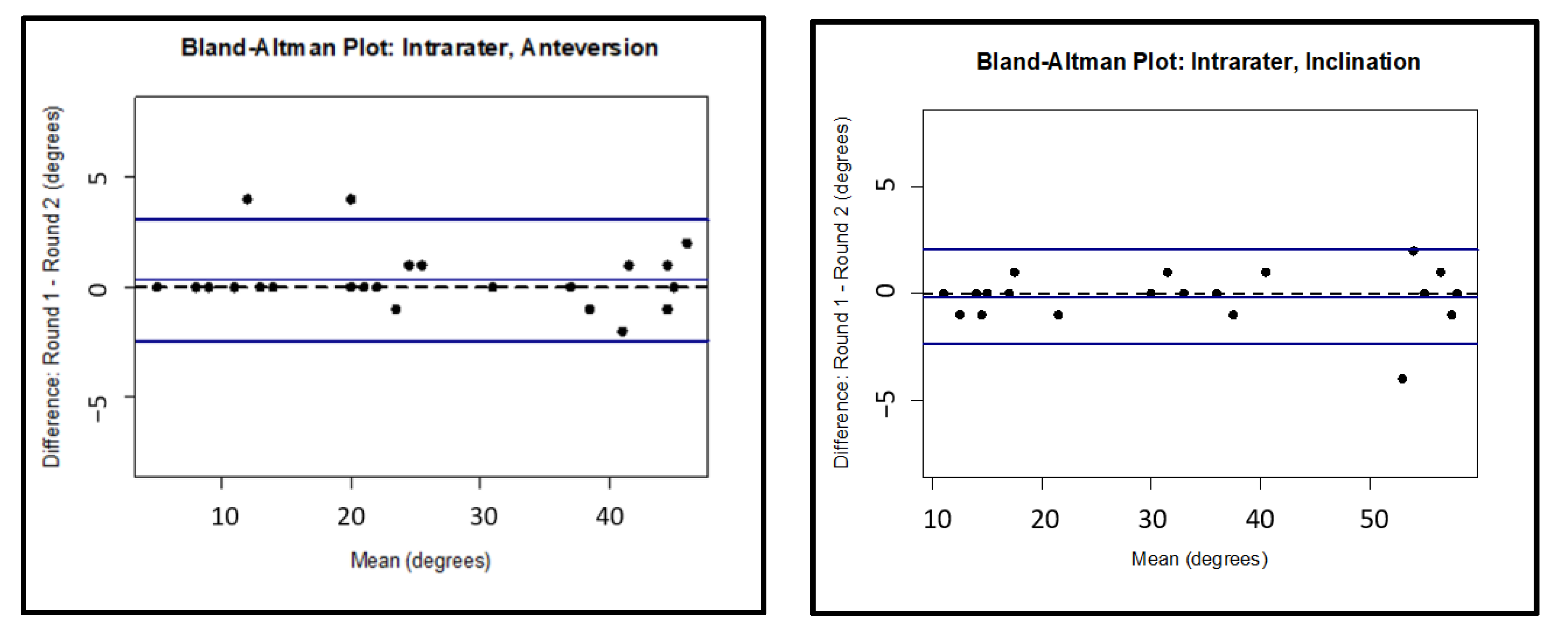
| Intrarater | |||||||
|---|---|---|---|---|---|---|---|
| ICC | 95% CI Lower Border | 95% CI Upper Border | Bias | Lower LOA | Upper LOA | ||
| Anteversion | Cup Only | 0.995 | 0.985 | 0.998 | 0.320 | −2.432 | 3.072 |
| Cup plus Small Head | 0.983 | 0.952 | 0.995 | −1.500 | −5.295 | 2.295 | |
| Cup plus Big Head | 0.985 | 0.971 | 0.993 | −0.722 | −5.210 | 3.766 | |
| Inclination | Cup Only | 0.998 | 0.994 | 0.999 | −0.160 | −2.372 | 2.052 |
| Cup plus Small Head | 0.999 | 0.998 | 1.000 | −0.188 | −1.856 | 1.481 | |
| Cup plus Big Head | 0.999 | 0.997 | 0.999 | −0.056 | −1.801 | 1.690 |
| Interrater | |||||||
|---|---|---|---|---|---|---|---|
| ICC | 95% CI Lower Border | 95% CI Upper Border | Bias | Lower LOA | Upper LOA | ||
| Anteversion | Cup Only | 0.988 | 0.976 | 0.995 | −0.160 | −4.429 | 4.109 |
| Cup plus Small Head | 0.941 | 0.868 | 0.976 | −3.625 | −8.834 | 1.584 | |
| Cup plus Big Head | 0.940 | 0.871 | 0.974 | −3.056 | −10.459 | 4.348 | |
| Inclination | Cup Only | 0.997 | 0.991 | 0.998 | −1.040 | −3.160 | 1.080 |
| Cup plus Small Head | 0.996 | 0.989 | 0.998 | −1.438 | −3.499 | 0.624 | |
| Cup plus Big Head | 0.996 | 0.988 | 0.999 | −0.833 | −3.512 | 1.846 |
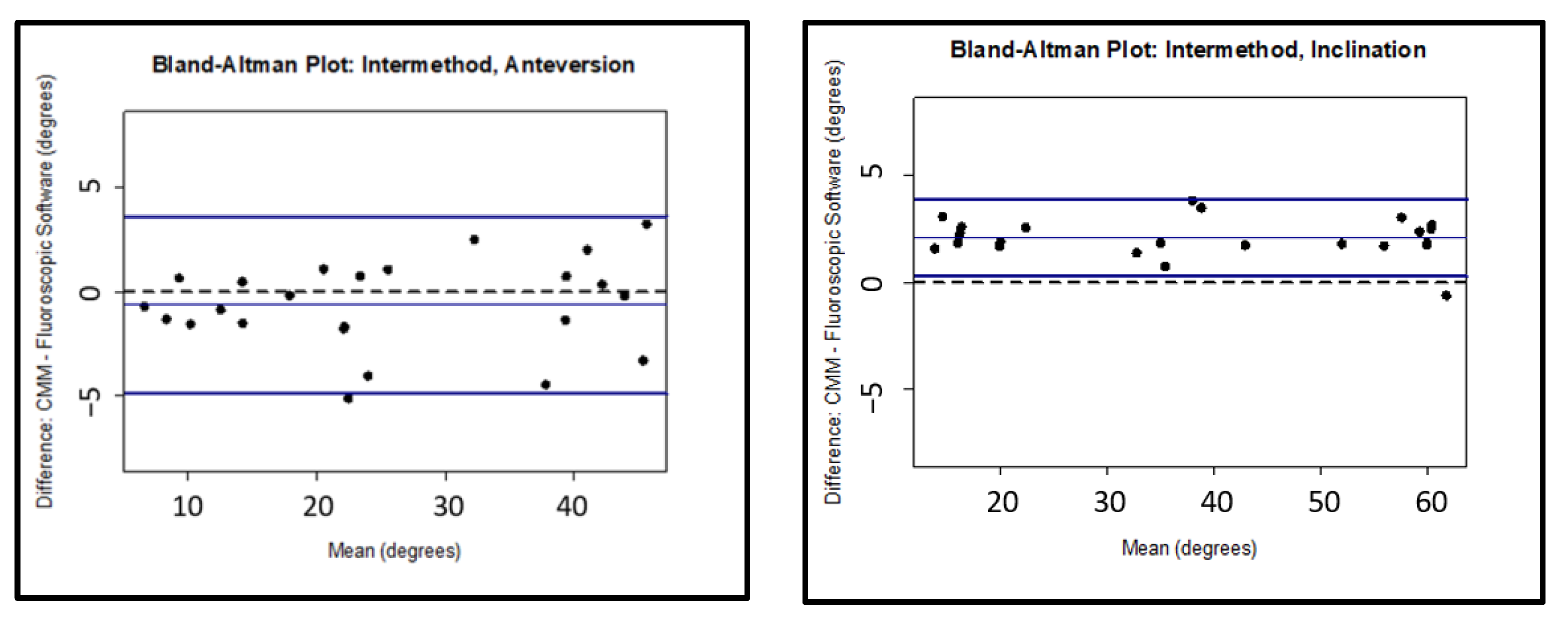
| Intermethod | |||||||
|---|---|---|---|---|---|---|---|
| ICC | 95% CI Lower Border | 95% CI Upper Border | Bias | Lower LOA | Upper LOA | ||
| Anteversion | Cup Only | 0.986 | 0.969 | 0.993 | −0.631 | −4.886 | 3.625 |
| Cup plus Small Head | 0.978 | 0.941 | 0.994 | −0.994 | −6.094 | 4.106 | |
| Cup plus Big Head | 0.966 | 0.912 | 0.989 | −1.271 | −7.791 | 5.249 | |
| Inclination | Cup Only | 0.993 | 0.988 | 0.995 | 2.083 | 0.282 | 3.885 |
| Cup plus Small Head | 0.993 | 0.989 | 0.995 | 2.133 | 0.182 | 4.084 | |
| Cup plus Big Head | 0.988 | 0.982 | 0.992 | 2.438 | −0.147 | 5.022 |
Publisher’s Note: MDPI stays neutral with regard to jurisdictional claims in published maps and institutional affiliations. |
© 2022 by the authors. Licensee MDPI, Basel, Switzerland. This article is an open access article distributed under the terms and conditions of the Creative Commons Attribution (CC BY) license (https://creativecommons.org/licenses/by/4.0/).
Share and Cite
Brady, A.W.; Tatka, J.; Fagotti, L.; Kemler, B.R.; Fossum, B.W. Accuracy and Reliability of Software Navigation for Acetabular Component Placement in THA: An In Vitro Validation Study. Medicina 2022, 58, 663. https://0-doi-org.brum.beds.ac.uk/10.3390/medicina58050663
Brady AW, Tatka J, Fagotti L, Kemler BR, Fossum BW. Accuracy and Reliability of Software Navigation for Acetabular Component Placement in THA: An In Vitro Validation Study. Medicina. 2022; 58(5):663. https://0-doi-org.brum.beds.ac.uk/10.3390/medicina58050663
Chicago/Turabian StyleBrady, Alex W., Jakub Tatka, Lorenzo Fagotti, Bryson R. Kemler, and Bradley W. Fossum. 2022. "Accuracy and Reliability of Software Navigation for Acetabular Component Placement in THA: An In Vitro Validation Study" Medicina 58, no. 5: 663. https://0-doi-org.brum.beds.ac.uk/10.3390/medicina58050663