
Systematic Review of Clinical Applications of CAD/CAM Technology for Craniofacial Implants Placement and Manufacturing of Nasal Prostheses

 , and
, and
Abstract
:1. Introduction
2. Experimental Section
2.1. Search Strategy
2.2. Eligibility Criteria
2.3. Source of Information
2.4. Study Selection
2.5. Data Extraction
2.6. Risk of Bias in Individual Studies
3. Results
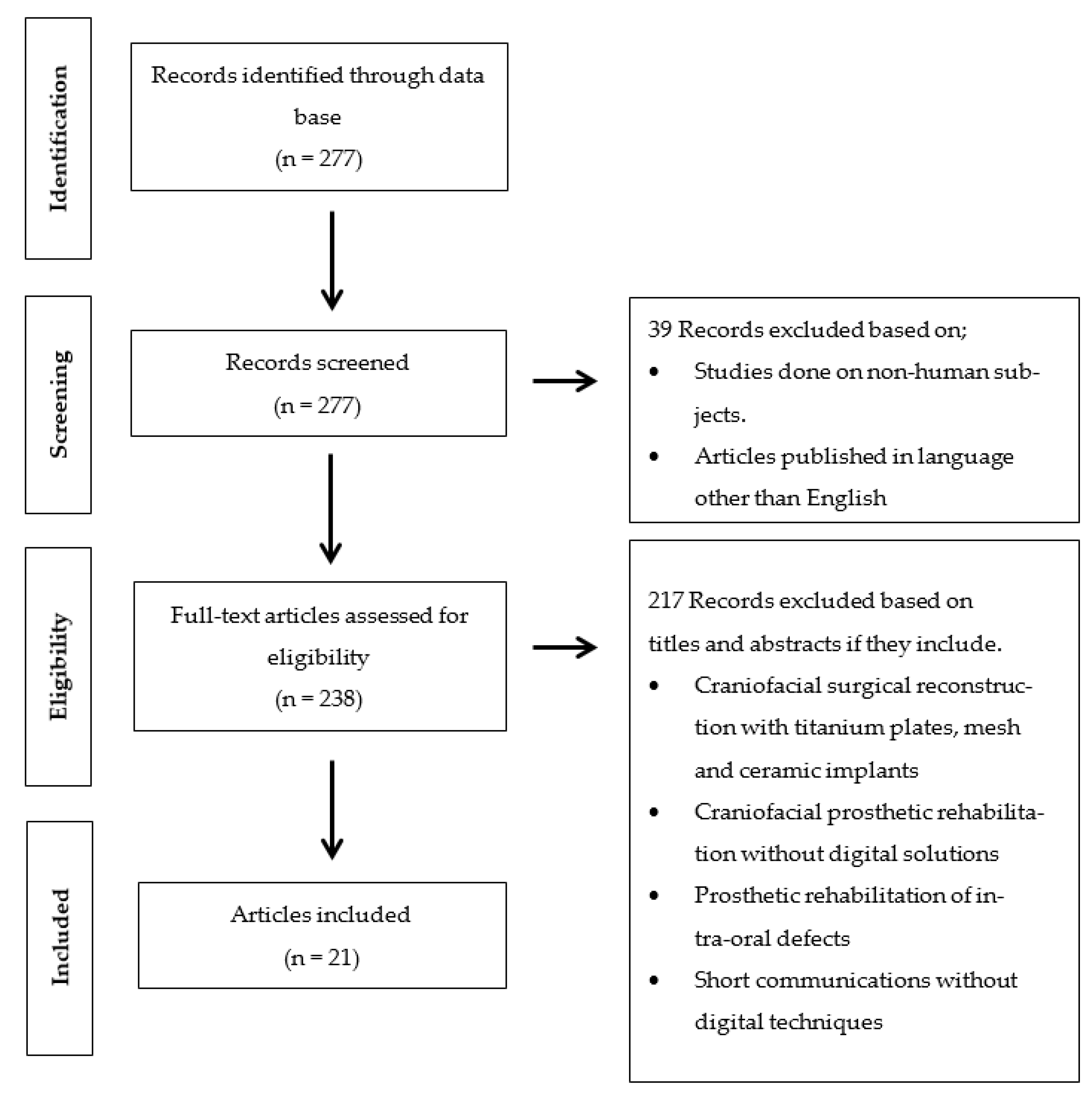
3.1. Study Selection
3.2. Study Characteritics
3.2.1. Applications of CAD/CAM Technology for Surgical and Prosthetic Purpose
3.2.2. Preoperative Planning
3.2.3. Printing Equipment Devices
3.2.4. Guided Implants Surgery
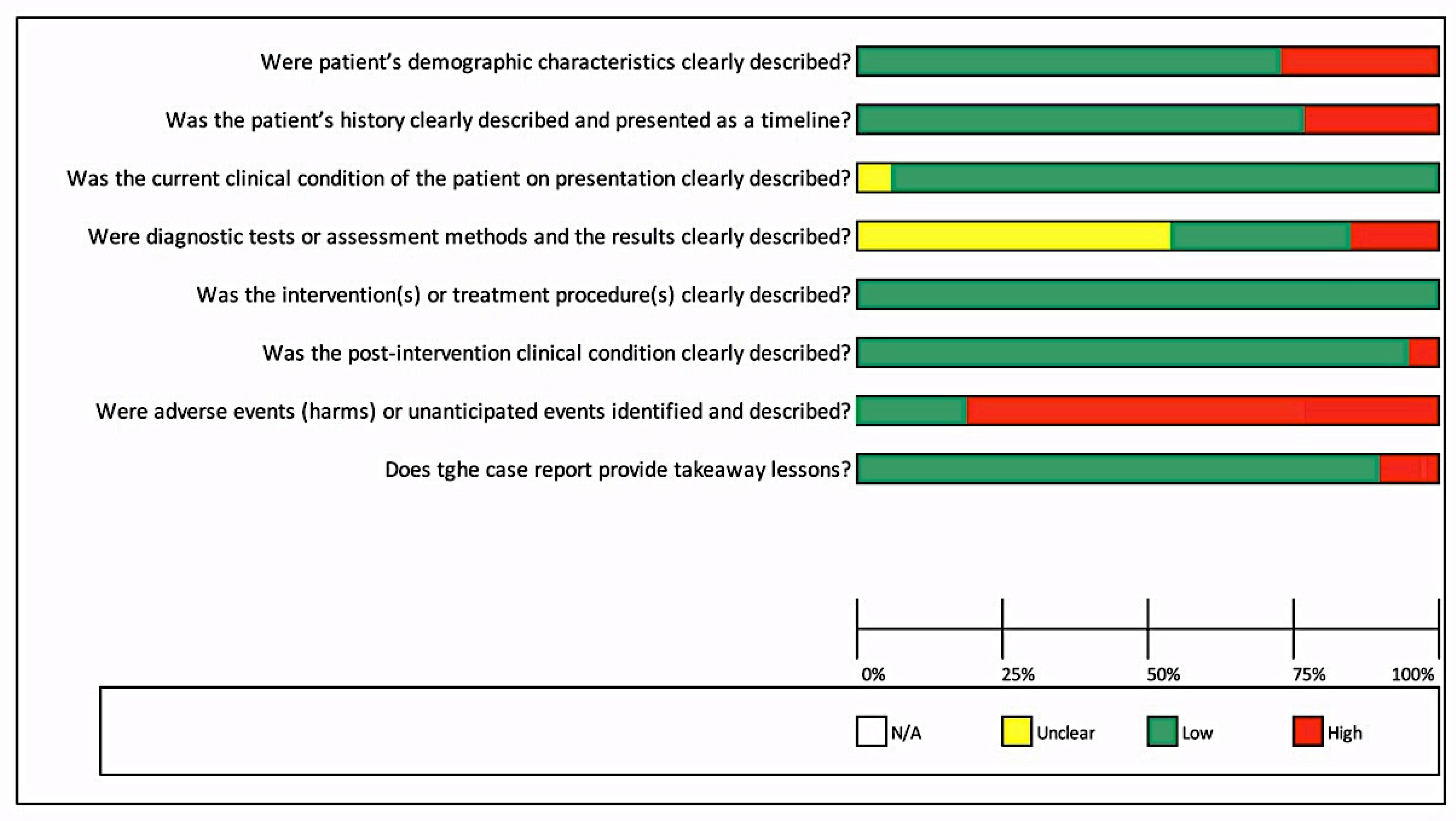
3.3. Risks of Bias in Individual Studies
4. Discussion
5. Conclusions
Author Contributions
Funding
Institutional Review Board Statement
Informed Consent Statement
Data Availability Statement
Conflicts of Interest
References
- Dings, J.P.J.; Merkx, M.A.W.; de Clonie Maclennan-Naphausen, M.T.P.; van de Pol, P.; Maal, T.J.J.; Meijer, G.J. Maxillofacial prosthetic rehabilitation: A survey on the quality of life. J. Prosthet. Dent. 2018, 120, 780–786. [Google Scholar] [CrossRef] [PubMed]
- Atay, A.; Peker, K.; Günay, Y.; Ebrinç, S.; Karayazgan, B.; Uysal, Ö. Assessment of health-related quality of life in Turkish patients with facial prostheses. Health Qual. Life Outcomes. 2013, 26, 11. [Google Scholar] [CrossRef] [Green Version]
- Depprich, R.; Naujoks, C.; Lind, D.; Ommerborn, M.; Meyer, U.; Kübler, N.R.; Handschel, J. Evaluation of the quality of life of patients with maxillofacial defects after prosthodontic therapy with obturator prostheses. Int. J. Oral. Maxillofac. Surg. 2011, 40, 71–79. [Google Scholar] [CrossRef]
- Buzayan, M.M. Prosthetic management of mid-facial defect with magnet-retained silicone prosthesis. Prosthet. Orthot. Int. 2014, 38, 62–67. [Google Scholar] [CrossRef] [Green Version]
- Gastaldi, G.; Palumbo, L.; Moreschi, C.; Gherlone, E.F.; Capparé, P. Prosthetic management of patients with oro-maxillo-facial defects: A long-term follow-up retrospective study. Oral. Implantol. (Rome) 2017, 10, 276–282. [Google Scholar] [CrossRef]
- Heinz, M.B.; Ghanepur, H.; Ghassemi, A. Two-Step Reconstruction of Non-Marginal Auricular Defects. J. Oral. Maxillofac. Surg. 2016, 74, 1494–1498. [Google Scholar] [CrossRef]
- Connolly, T.M.; Sweeny, L.; Greene, B.; Morlandt, A.; Carroll, W.R.; Rosenthal, E.L. Reconstruction of midface defects with the osteocutaneous radial forearm flap: Evaluation of long term outcomes including patient reported quality of life. Microsurgery 2017, 37, 752–762. [Google Scholar] [CrossRef]
- Loh, H.S.; Tan, P.H. Prosthodontic management of maxillofacial defects after cancer surgery. Singap. Med. J. 1989, 30, 74–78. [Google Scholar]
- Ciocca, L.; Fantini, M.; De Crescenzio, F.; Persiani, F.; Scotti, R. Computer-aided design and manufacturing construction of a surgical template for craniofacial implant positioning to support a definitive nasal prosthesis. Clin. Oral. Implant. Res. 2011, 22, 850–856. [Google Scholar] [CrossRef]
- Plath, M.; Thielen, H.M.; Baumann, I.; Zaoui, K.; Federspil, P.A. Tumor Control and Quality of Life in Skin Cancer Patients with Extensive Multilayered Nasal Defects. Clin. Exp. Otorhinolaryngol. 2020, 13, 164–172. [Google Scholar] [CrossRef] [PubMed]
- Ali, K.; Trost, J.G.; Truong, T.A.; Harshbarger, R.J., 3rd. Total Ear Reconstruction Using Porous Polyethylene. Semin. Plast. Surg. 2017, 31, 161–172. [Google Scholar] [CrossRef] [PubMed]
- Cobein, M.V.; Coto, N.P.; Junior, O.C.; Lemos, J.B.D.; Vieira, L.M.; Pimentel, M.L.; Byrne, H.J.; Dias, R.B. Retention systems for extraoral maxillofacial prosthetic implants: A critical review. Br. J. Oral. Maxillofac. Surg. 2017, 55, 763–769. [Google Scholar] [CrossRef] [PubMed]
- Chang, T.L.; Garrett, N.; Roumanas, E.; Beumer, J., 3rd. Treatment satisfaction with facial prostheses. J. Prosthet. Dent. 2005, 94, 275–280. [Google Scholar] [CrossRef] [PubMed]
- Dos Reis, H.B.; de Oliveira, J.A.P.; Pecorari, V.A.; Raoufi, S.; Abrahão, M.; Dib, L.L. Extraoral Implants for Anchoring Facial Prostheses: Evaluation of Success and Survival Rates in Three Anatomical Regions. Int. J. Oral. Maxillofac. Implants. 2017, 32, 385–391. [Google Scholar] [CrossRef] [PubMed] [Green Version]
- Nishimura, R.D.; Roumanas, E.; Moy, P.K.; Sugai, T. Nasal defects and osseointegrated implants: UCLA experience. J. Prosthet. Dent. 1996, 76, 597–602. [Google Scholar] [CrossRef]
- Wang, R. Preoperative auricular wax pattern duplication for surgical template fabrication. J. Prosthet. Dent. 1999, 81, 634–637. [Google Scholar] [CrossRef]
- Datarkar, A.; Daware, S.; Dande, R.; Datarkar, U. Rehabilitation of Unilateral Congenital Microtia by Implant-retained Prosthesis. Ann. Maxillofac. Surg. 2017, 7, 291–295. [Google Scholar] [CrossRef] [PubMed]
- Elbashti, M.E.; Sumita, Y.I.; Kelimu, S.; Aswehlee, A.M.; Awuti, S.; Hattori, M.; Taniguchi, H. Application of Digital Technologies in Maxillofacial Prosthetics Literature: A 10-Year Observation of Five Selected Prosthodontics Journals. Int. J. Prosthodont. 2019, 32, 45–50. [Google Scholar] [CrossRef]
- Van der Meer, W.J.; Raghoebar, G.M.; Gerrits, P.O.; Noorda, W.D.; Vissink, A.; Visser, A. Digitally designed surgical guides for placing implants in the nasal floor of dentate patients: A series of three cases. Int. J. Prosthodont. 2012, 25, 245–251. [Google Scholar]
- Verma, S.; Gonzalez, M.; Schow, S.R.; Triplett, R.G. Virtual Preoperative Planning and Intraoperative Navigation in Facial Prosthetic Reconstruction: A Technical Note. Int. J. Oral. Maxillofac. Implants. 2017, 32, e77–e81. [Google Scholar] [CrossRef] [Green Version]
- Moher, D.; Liberati, A.; Tetzlaff, J.; Altman, D.G.; PRISMA Group. Preferred reporting items for systematic reviews and meta-analyses: The PRISMA statement. PLoS Med. 2009, 6, e1000097. [Google Scholar] [CrossRef] [Green Version]
- Moola, S.M.Z.; Tufanaru, C.; Aromataris, E.; Sears, K.; Sfetcu, R.; Currie, M.; Lisy, K.; Qureshi, R.; Mattis, P.; Mu, P. Chapter 7: Systematic reviews of etiology and risk. In Joanna Briggs Institute Reviewer’s Manual; Aromataris, E., Munn, Z., Eds.; JBI: Adelaide, Australia, 2017. [Google Scholar] [CrossRef]
- Ciocca, L.; De Crescenzio, F.; Fantini, M.; Scotti, R. Rehabilitation of the nose using CAD/CAM and rapid prototyping technology after ablative surgery of squamous cell carcinoma: A pilot clinical report. Int. J. Oral. Maxillofac. Implants. 2010, 25, 808–812. [Google Scholar]
- Wälivaara, D.Å; Isaksson, S.; Johansson, L.Å. Frontal bone and modified zygomatic implants for retention of a nasal prosthesis: Surgical planning using a three-dimensional computer software program. J. Plast Surg. Hand Surg. 2011, 45, 109–112. [Google Scholar] [CrossRef]
- Ciocca, L.; Fantini, M.; De Crescenzio, F.; Persiani, F.; Scotti, R. New protocol for construction of eyeglasses-supported provisional nasal prosthesis using CAD/CAM techniques. J. Rehabil. Res. Dev. 2010, 47, 595–604. [Google Scholar] [CrossRef] [PubMed]
- Toso, S.M.; Menzel, K.; Motzkus, Y.; Adolphs, N.; Hoffmeister, B.; Raguse, J.D. Patient-Specific Implant in Prosthetic Craniofacial Reconstruction: First Report of a Novel Technique with Far-Reaching Perspective. J. Craniofac. Surg. 2015, 26, 2133–2135. [Google Scholar] [CrossRef]
- Buzayan, M.M.; Yunus, N.B.; Oon, H.K.; Tawfiq, O. Virtual Treatment Planning for Implant-Retained Nasal Prosthesis: A Clinical Report. Int. J. Oral. Maxillofac. Implants. 2017, 32, 255–e258. [Google Scholar] [CrossRef] [Green Version]
- Dawood, A.; Tanner, S.; Hutchison, I. A new implant for nasal reconstruction. Int. J. Oral. Maxillofac. Implants. 2012, 27, 90–92. [Google Scholar]
- Unkovskiy, A.; Spintzyk, S.; Brom, J.; Huettig, F.; Keutel, C. Direct 3D printing of silicone facial prostheses: A preliminary experience in digital workflow. J. Prosthet. Dent. 2018, 120, 303–308. [Google Scholar] [CrossRef] [PubMed]
- McHutchion, L.; Kincade, C.; Wolfaardt, J. Integration of digital technology in the workflow for an osseointegrated implant-retained nasal prosthesis: A clinical report. J. Prosthet. Dent. 2019, 121, 858–862. [Google Scholar] [CrossRef] [PubMed]
- Qiu, J.; Gu, X.Y.; Xiong, Y.Y.; Zhang, F.Q. Nasal prosthesis rehabilitation using CAD-CAM technology after total rhinectomy: A pilot study. Support. Care Cancer. 2011, 19, 1055–1059. [Google Scholar] [CrossRef]
- Reitemeier, B.; Götzel, B.; Schöne, C.; Stockmann, F.; Müller, R.; Lexmann, J.; Meissner, H. Creation and utilization of a digital database for nasal prosthesis models. Onkologie 2013, 36, 7–11. [Google Scholar] [CrossRef] [PubMed]
- Grant, G.T.; Aita-Holmes, C.; Liacouras, P.; Garnes, J.; Wilson, W.O., Jr. Digital capture, design, and manufacturing of a facial prosthesis: Clinical report on a pediatric patient. J. Prosthet. Dent. 2015, 114, 138–141. [Google Scholar] [CrossRef] [PubMed]
- Ciocca, L.; Tarsitano, A.; Marchetti, C.; Scotti, R. Updates on the Construction of an Eyeglass-Supported Nasal Prosthesis Using Computer-Aided Design and Rapid Prototyping Technology. J. Prosthodont. 2016, 25, 61–65. [Google Scholar] [CrossRef] [PubMed]
- Palousek, D.; Rosicky, J.; Koutny, D. Use of digital technologies for nasal prosthesis manufacturing. Prosthet. Orthot. Int. 2014, 38, 171–175. [Google Scholar] [CrossRef] [PubMed] [Green Version]
- Dawood, A.; Kalavrezos, N.; Barrett, M.; Tanner, S. Percutaneous implant retention of a nasal prosthesis. J. Prosthet. Dentistry. 2017, 117, 186–190. [Google Scholar] [CrossRef]
- Neto, R.; Costa-Ferreira, A.; Leal, N.; Machado, M.; Reis, A. An engineering-based approach for design and fabrication of a customized nasal prosthesis. Prosthet. Orthot. Int. 2015, 39, 422–428. [Google Scholar] [CrossRef]
- Nuseir, A.; Hatamleh, M.M.; Alnazzawi, A.; Al-Rabab'ah, M.; Kamel, B.; Jaradat, E. Direct 3D Printing of Flexible Nasal Prosthesis: Optimized Digital Workflow from Scan to Fit. J. Prosthodont. 2019, 28, 10–14. [Google Scholar] [CrossRef] [Green Version]
- Vera, C.; Barrero, C.; Shockley, W.; Rothenberger, S.; Minsley, G.; Drago, C. Prosthetic reconstruction of a patient with an acquired nasal defect using extraoral implants and a CAD/CAM copy-milled bar. J. Prosthodont. 2014, 23, 582–587. [Google Scholar] [CrossRef]
- Yoshioka, F.; Ozawa, S.; Hyodo, I.; Tanaka, Y. Innovative Approach for Interim Facial Prosthesis Using Digital Technology. J. Prosthodont. 2016, 25, 498–502. [Google Scholar] [CrossRef]
- Tso, T.V.; Tso, V.J.; Stephens, W.F. Prosthetic rehabilitation of an extensive midfacial and palatal postsurgical defect with an implant-supported cross arch framework: A clinical report. J. Prosthet. Dent. 2015, 113, 498–502. [Google Scholar] [CrossRef]
- Ewers, R.; Schicho, K.; Truppe, M.; Seemann, R.; Reichwein, A.; Figl, M.; Wagner, A. Computer-aided navigation in dental implantology: 7 years of clinical experience. J. Oral Maxillofac. Surg. 2004, 62, 329–334. [Google Scholar] [CrossRef] [PubMed]
- Mupparapu, M.; Singer, S.R. Implant imaging for the dentist. J. Can. Dent. Assoc. 2004, 70, 32. [Google Scholar]
- van Eijnatten, M.; Berger, F.H.; de Graaf, P.; Koivisto, J.; Forouzanfar, T.; Wolff, J. Influence of CT parameters on STL model accuracy. Rapid Prototyp. J. 2017, 23, 678–685. [Google Scholar] [CrossRef]
- Choi, J.Y.; Choi, J.H.; Kim, N.K.; Kim, Y.; Lee, J.K.; Kim, M.K.; Lee, J.H.; Kim, M.J. Analysis of errors in medical rapid prototyping models. Int. J. Oral Maxillofac. Surg. 2002, 31, 23–32. [Google Scholar] [CrossRef] [PubMed]
- Whyms, B.J.; Vorperian, H.K.; Gentry, L.R.; Schimek, E.M.; Bersu, E.T.; Chung, M.K. The effect of computed tomographic scanner parameters and 3-dimensional volume rendering techniques on the accuracy of linear, angular, and volumetric measurements of the mandible. Oral Surg. Oral Med. Oral Pathol. Oral Radiol. 2013, 115, 682–691. [Google Scholar] [CrossRef] [PubMed] [Green Version]
- Taft, R.M.; Kondor, S.; Grant, G.T. Accuracy of rapid prototype models for head and neck reconstruction. J. Prosthet. Dent. 2011, 106, 399–408. [Google Scholar] [CrossRef]
- Eggbeer, D.; Bibb, R.; Evans, P.; Ji, L. Evaluation of direct and indirect additive manufacture of maxillofacial prostheses. Proceedings of the Institution of Mechanical Engineers Part H. J. Eng. Med. 2012, 226, 718–728. [Google Scholar] [CrossRef]
- Jindal, S.K.; Sherriff, M.; Waters, M.G.; Coward, T.J. Development of a 3D printable maxillofacial silicone: Part I. Optimization of polydimethylsiloxane chains and cross-linker concentration. J. Prosthet. Dent. 2016, 116, 617–622. [Google Scholar] [CrossRef] [Green Version]
- Jindal, S.K.; Sherriff, M.; Waters, M.G.; Smay, J.E.; Coward, T.J. Development of a 3D printable maxillofacial silicone: Part II. Optimization of moderator and thixotropic agent. J. Prosthet. Dent. 2018, 119, 299–304. [Google Scholar] [CrossRef]
- Verma, S.N.; Schow, S.R.; Stone, B.H.; Triplett, R.G. Applications of surgical navigational systems for craniofacial bone-anchored implant placement. Int. J. Oral Maxillofac. Implant. 2010, 25, 582–588. [Google Scholar]
- Meltzer, N.E.; Garcia, J.R.; Byrne, P.J.; Boahene, D.K. Image-guided titanium implantation for craniofacial prosthetics. Arch. Facial Plast. Surg. 2009, 11, 58–61. [Google Scholar] [CrossRef] [PubMed]
- Girod, S.C.; Rohlfing, T.; Maurer, C.R., Jr. Image-guided surgical navigation in implant-based auricular reconstruction Journal of oral and maxillofacial surgery: Official journal of the American. Assoc. Oral Maxillofac. Surg. 2008, 66, 1302–1306. [Google Scholar] [CrossRef] [PubMed]
- Bell, R.B. Computer planning and intraoperative navigation in cranio-maxillofacial surgery. Oral Maxillofac. Surg. Clin. N. Am. 2010, 22, 135–156. [Google Scholar] [CrossRef]
- Weissler, J.M.; Sosin, M.; Dorafshar, A.H.; Garcia, J.R. Combining Virtual Surgical Planning, Intraoperative Navigation, and 3-Dimensional Printing in Prosthetic-Based Bilateral Microtia Reconstruction. J. Oral Maxillofac. Surg. 2017, 75, 1491–1497. [Google Scholar] [CrossRef] [PubMed]
- Choi, K.J.; Sajisevi, M.B.; McClennen, J.; Kaylie, D.M. Image-Guided Placement of Osseointegrated Implants for Challenging Auricular, Orbital, and Rhinectomy Defects. Ann. Otol. Rhinol. Laryngol. 2016, 125, 801–807. [Google Scholar] [CrossRef] [PubMed]
- Zweifel, D.F.; Simon, C.; Hoarau, R.; Pasche, P.; Broome, M. Are virtual planning and guided surgery for head and neck reconstruction economically viable? J. Oral Maxillofac. Surg. 2015, 73, 170–175. [Google Scholar] [CrossRef] [PubMed]


| Author | Prosthesis | Nº of Cases | Purpose of Software Planning | Pre-Op Data for Digital Planning | Software | Printer/Miller | Printing Materials | Navigation System (Yes/No) | Location and Nº of Implants | Implants System | Post-Op Evaluation |
|---|---|---|---|---|---|---|---|---|---|---|---|
| Ciocca et al. 2011 [9] | Nasal prosthesis | 1 | Surgical template for implants placement | CT, laser scan; NextEngine Desktop 8 | NobelGuide software 1, Amira 3.1.1 software 2, Rapidform XOS2 3, Rhino 3.0 4 | Stratasys 21 | Acrylonitrile butadiene styrene plastic material (ABS P400) | No | Glabella; 1 implant. Pre-maxilla; 2 implants | Implants (Branemark System RP TiUnite, Nobel Biocare) | CT scan |
| Van der Meer et al. 2012 [19] | Nasal prosthesis | 3 | Surgical template for implants placement | CBCT, Lava COS intraoral scanner 14 | Mimics software 5, 3ds Max 6, Geomagic Studio 7 | DSM Desotech | Biocompatible SLA resin (BioSure, DSM Desotech) | No | Maxilla; 2 implants/defect site. 6 implants in 3 patients | Brånemark, Nobel Biocare | CBCT |
| Ciocca et al. 2010 [23] | Nasal prosthesis | 1 | Fabrication of mold for nasal prosthesis | CT, laser scan; NextEngine 8 | Next Engine software 8, Rapidform software 3 | Stratasys 21 | Acrylonitrile butadiene styrene (ABS) | No | Maxilla; 2 implants | MKIII TiUnite Nobel Biocare | None |
| Walivaara et al. 2011 [24] | Nasal prosthesis | 1 | Surgical template for implants placement | CT | SimPlant Planner 9.2 9 | NM | NM | No | Zygomatic bone; 2 implants, Nasofrontal bone; 1 implant | Branemark implants (Brånemark Integration Inc.) | None |
| Ciocca et al. 2010 [25] | Nasal prosthesis | 1 | Fabrication substructure for eyeglasses and mold for nasal prosthesis | Laser scan; NextEngine Desktop 8, Laser surface scan VIVID 900 15 | Rapidform XOS software 3, Rhino 4.0 4 | Stratasys 21 | Acrylonitrile butadiene styrene (ABS) | No | No implants | No implants | None |
| Toso et al. 2015 [26] | Nasal prosthesis | 1 | Fabrication of nasal implant | CT | 3D-modeling software, ZBrush 10 | NM | Titanium alloy Ti6Al4V | No | Glabella and lateral process of maxilla; customized implant; 1 | KLS Martin Group, Tuttlingen, Germany | None |
| Buzayan et al. 2017 [27] | Nasal prosthesis | 1 | Surgical template for implants placement | CBCT | Software (Corel PaintShop Pro X4 version 14.0.0.322), Simplant software 9 | NM | NM | No | Maxilla; 2 implants | Implatium; Bone Level | None |
| Dawood et al. 2012 [28] | Nasal prosthesis | 1 | Surgical template for implants placement, Designing and manufacturing of bifunctional implants | NM | Nobel Guide, Nobel Biocare 1 | NM | Type IV titanium | No | Maxilla; 2 implants | NM | None |
| Unkovskiy et al. 2018 [29] | Nasal prosthesis | 1 | Direct printing of silicone prosthesis | Stationery 3D photogrammetry system: pritiface; pritidenta 16, light scanner: Artec Spider; Artec 3D | Zbrush Software 10 | Printer (Drop-on-Demand ACEO; Wacker Chemie AG) | Silicone free of solvents (ACEO Silicone General Purpose; Wacker Chemie AG) | No | Nasal cavity floor; 3 implants | Vistafix 2; Cohlear Ltd. | None |
| McHutchion et al. 2019 [30] | Nasal prosthesis | 1 | Surgical template for implants placement, Nose prosthesis prototype and substructure | CBCT | Mimics 5, Geomagic Freeform Plus 7, Software ZBrush software 10 | Fortus 400mc; Stratasys 21 | Thermoplastic material (PC-ISO; Stratasys, Ltd.), thermoplastic material (ABSplus-P430; Stratasys, Ltd.) | No | Right and left zygoma; 2 implants. Right and left lateral maxilla; 2 implants. Glabella; 1 implant | Branemark Systems; Nobel Biocare, Southern Implants | None |
| Qiu et al. 2011 [31] | Nasal prosthesis | 1 | Fabrication of mold for nasal prosthesis | CT | Mimics software 5, Geomagic Studio 9.0 7 | Stereolithography unit (RS4500) | Photopolymer (WaterShed XC, DSM Somos, Elgin, IL, USA) | No | No implants | No implants | None |
| Reitemeier et al. 2013 [32] | Nasal prosthesis | 1 | Creation of digital nose database | 3D Scan; G scan IVB 17 | epiTecture software 13, Geomagic studio 9.0 7 | NM | NM | No | No implants | No implants | None |
| Grant et al. 2015 [33] | Nasal prosthesis | 1 | Fabrication of mold for nasal prosthesis | Digital image; 3dMDcranial system 20 | Materialise: Free-form software 12 | Binder jetting technique (ProJet 460 plus; 3D Systems) | Cyanoacrylate resin (Apollo 5005 Cyano- acrylate; Cyberbond) | No | No implants | No implants | None |
| Ciocca et al. 2016 [34] | Nasal prosthesis | 1 | Designing of substructure | 3D laser scanner; 3dMDface System 19 | Freeform Modeling Plus software and Phantom Desktop Haptic device 12 | Eosint P100 Formiga 22 | Polyamide resin and laser-melted cobalt-chrome framework | No | No implants | No implants | None |
| Palousek et al. 2014 [35] | Nasal prosthesis | 1 | Designing and rapid prototyping of nose model | 3D scan, light scanner; ATOS III 18 | Rhinoceros software 4 | ZPrinter 310 Plus 23 | NM | No | No implants | No implants | None |
| Dawood et al. 2017 [36] | Nasal prosthesis | 1 | Fabrication of surgical guide, milling of titanium overdenture bar | CBCT | Nobel- Clinician; NobelBiocare. Procera over-denture bar; Nobel Biocare) | Nobel Biocare | NM | No | No implants | No implants | None |
| Neto et al. 2014 [37] | Nasal prosthesis | 1 | Fabrication of mold for nasal prosthesis | CT scans, light scanner; ATOS III 18 | Mimics 16.0 5 | SL-stereolithography; ViperTM SLA System 24 | NM | No | No implants | No implants | None |
| Nuseir et al. 2019 [38] | Nasal prosthesis | 1 | Direct printing of nasal prosthesis | CT scan | Materialise software (CMF Pro Plan 11, ZBrush software 10 | Stratasys 21 | TangoPlus (Stratasys Ltd.) | No | No implants | No implants | None |
| Vera et al. 2014 [39] | Nasal prosthesis | 1 | Fabrication of CAD/CAM copy milled framework for nasal prosthesis | NM | NM | NM | Acrylic resin | No | Anterior maxilla and glabella. Total 3 implants | Vistafix System, Cochlear Corp, Englewood, CO | None |
| Yoshioka et al. 2016 [40] | Nasal prosthesis | 1 | Surgical template and model for fabricating substructure | CT, 3D scan Rexcan 3 25 | Software (Geomagic Studio 7, FreeForm Modeling software 12 | 3D milling machine MDX-40 26 | Dental stone New Plastone 2 27 | No | No implants | No implants | None |
| Tso et al. 2015 [41] | Facial prosthesis | 1 | Fabrication of surgical template | CT scan | NobelGuide 1 | CAD/CAM machine (Röder RXD5) | NM | No | Right zygoma, left zygoma, right infraorbital rim, left infraorbital rim, nasal and right tuberosity. Total 6 implants | Nobel Biocare | None |
| Assessment | Author and Year | ||||||
|---|---|---|---|---|---|---|---|
| Ciocca et al. 2011 [9] | Ciocca et al. 2010 [23] | Walivaara et al. 2011 [24] | Ciocca et al. 2010 [25] | Toso et al. 2015 [26] | Buzayan et al. 2017 [27] | Dawood et al. 2012 [28] | |
| Were patient’s demographic characteristics clearly described? | Yes | Yes | Yes | Yes | Yes | Yes | No |
| Was the patient’s history clearly described and presented as a timeline? | Yes | Yes | Yes | Yes | Yes | Yes | No |
| Was the current clinical condition of the patient on presentation clearly described? | Yes | Yes | Yes | Yes | Yes | Yes | Yes |
| Were diagnostic tests or assessment methods and the results clearly described? | Unclear | Unclear | Unclear | Unclear | Unclear | Unclear | Unclear |
| Was the intervention(s) or treatment procedure(s) clearly described? | Yes | Yes | Yes | Yes | Yes | Yes | Yes |
| Was the post-intervention clinical condition clearly described? | Yes | Yes | Yes | Yes | Yes | No | Yes |
| Were adverse events (harms) or unanticipated events identified and described? | No | No | No | No | No | No | No |
| Does the case report provide takeaway lessons? | Yes | Yes | Yes | Yes | Yes | Yes | Yes |
| Overall appraisal | Included | Included | Included | Included | Included | Included | Included |
| Unkovskiy et al. 2018 [29] | McHutchion et al. 2019 [30] | Qiu et al. 2011 [31] | Reitemeier et al. 2013 [32] | Grant et al. 2015 [33] | Ciocca et al. 2016 [34] | Palousek et al. 2014 [35] | |
| Were patient’s demographic characteristics clearly described? | Yes | Yes | Yes | No | Yes | No | No |
| Was the patient’s history clearly described and presented as a timeline? | Yes | Yes | Yes | Yes | Yes | No | No |
| Was the current clinical condition of the patient on presentation clearly described? | Yes | Yes | Yes | Yes | Yes | Unclear | Yes |
| Were diagnostic tests or assessment methods and the results clearly described? | Unclear | Unclear | No | Unclear | Unclear | No | No |
| Was the intervention(s) or treatment procedure(s) clearly described? | Yes | Yes | Yes | Yes | Yes | Yes | Yes |
| Was the post-intervention clinical condition clearly described? | Yes | Yes | Yes | Yes | Yes | Yes | Yes |
| Were adverse events (harms) or unanticipated events identified and described? | Yes | No | No | No | No | Yes | No |
| Does the case report provide takeaway lessons? | Yes | Yes | Yes | Yes | Yes | Yes | Yes |
| Overall appraisal | Included | Included | Included | Included | Included | Included | Included |
| Dawood et al. 2017 [36] | Neto et al. 2014 [37] | Nuseir et al. 2019 [38] | Vera et al. 2014 [39] | Yoshioka et al. 2016 [40] | Tso et al. 2015 [41] | ||
| Were patient’s demographic characteristics clearly described? | Yes | Yes | Yes | Yes | Yes | Yes | |
| Was the patient’s history clearly described and presented as a timeline? | Yes | Yes | Yes | Yes | Yes | Yes | |
| Was the current clinical condition of the patient on presentation clearly described? | Yes | Yes | Yes | Yes | Yes | Yes | |
| Were diagnostic tests or assessment methods and the results clearly described? | Unclear | Unclear | Unclear | Yes | Yes | Yes | |
| Was the intervention(s) or treatment procedure(s) clearly described? | Yes | Yes | Yes | Yes | Yes | Yes | |
| Was the post-intervention clinical condition clearly described? | Yes | Yes | Yes | Yes | Yes | Yes | |
| Were adverse events (harms) or unanticipated events identified and described? | No | Yes | No | No | No | No | |
| Does the case report provide takeaway lessons? | Yes | Yes | Yes | Yes | Yes | No | |
| Overall appraisal | Included | Included | Included | Included | Included | Included | |
| Assessment | Author and Year |
|---|---|
| Van der Meer et al. 2012 [19] | |
| Were there clear criteria for inclusion in the case series? | Yes |
| Was the condition measured in a standard, reliable way for all participants included in the case series? | Unclear |
| Were valid methods used for identification of the condition for all participants included in the case series? | Yes |
| Did the case series have consecutive inclusion of participants? | Yes |
| Did the case series have complete inclusion of participants? | Yes |
| Was there clear reporting of the demographics of the participants in the study? | Unclear |
| Was there clear reporting of clinical information of the participants? | No |
| Were the outcomes or follow up results of cases clearly reported? | Yes |
| Was there clear reporting of the presenting site(s)/clinic(s) demographic information? | Yes |
| Overall appraisal | Included |
| Included Articles | Outcome | Recommendations | Limitations |
|---|---|---|---|
| Ciocca et al. 2011 [9] | Post-operative CT scan was done to assess the accuracy of preoperative planning. The implant in glabella had an angular deviation of 7.78° while two implants in premaxilla had an angular deviation of 1.86° and 4.55°. The apex with respect to implants position had deviated by 1.17 mm in glabella, while the implants in premaxilla deviated by 2.81 mm and 3.39 mm, respectively. | The helmet was designed on a rigid and fixed frontal surface of the patient, while the skin is resilient and mobile. Therefore, a bone pin retention system in the future would be better for stabilization of the template. | - |
| Van der Meer et al. 2012 [19] | Post-operative CBCT was made to analyze the difference between the planned position and actual position of each implant. Assessment revealed that all implants were placed within the limits needed for the fabrication of an optimal prosthesis, both from a surgical and prosthodontic perspective. | - | The slight mismatch between the planned position and actual position of implants may be caused by errors present in the different phases i.e., in the data acquisition phase, the resolution of the CBCT dataset, the accuracy of the system error in the data acquisition of the dentition, integration of the 3D model of the dentition with CBCT dataset errors, and the errors in the polymerization of the SLA material. |
| Ciocca et al. 2010 [23] | In vivo assessment was done after fabrication of prosthesis. The nasal prosthesis fitted over the defect well. There were no open margins found in the contact region. Furthermore, the connection between the eyeglasses and prosthesis was precise and unambiguous. The fitting was assessed by the Boolean volume difference calculated between the digital models. Furthermore, the mold resulted in a stable, secure position during silicone vulcanization. Considerable less time and cost was involved in manufacturing process. | The use of FDM rapid prototyping systems with thinner layers can improve the final result. Furthermore the silicone adhesive, which is usually used to fix the extrinsic coloring, may help to smooth the surface of the silicone, resulting in a homogenous appearance that eliminates the staircase effect. | The steps are still needed to create software to automate the procedure used to superimpose the model from the digital library onto the digital surface of the defect, to assist in the CAD/CAM bar construction. |
| Walivaara et al. 2011 [24] | Healing was uneventful. The final nasal prosthesis was retained using magnets attached to the implants. | Author recommends the use of computer-based techniques for planning implants in patients who are exposed to radiation therapy to minimize the need of surgical flaps. | - |
| Ciocca et al. 2010 [25] | The 3D printer used the FDM technique, which produced a very resistant mold and substructure with ABS material due to stable chemical and thermal properties. Time and cost of fabrication were significantly low | It was suggested that the printing direction should be parallel to the nose to reduce the staircase effect on printed silicone surface. Furthermore, to overcome the staircase effect on silicone surface, silicone adhesive and extrinsic stains can be used to obtain the homogenous surface appearance. | The limitation was the surface roughness produced by the staircase effect caused by the thickness of layers, which were copied in vulcanized silicone. |
| Toso et al. 2015 [26] | The patient-specific implant was inserted successfully by a paranasal and glabella approach. It fitted precisely three-dimensionally in the preoperative planned position. | Authors recommended the navigation-assisted control of position when typical anatomic reference points are missing. | - |
| Buzayan et al. 2017 [27] | Prior to the surgical placement of implant, digital planning was done to confirm that the proposed implant positions would not interfere with the future nasal prosthesis margins. That provided the ability to visualize the future prosthetic boundaries and form virtually. As a result, the implants were planned in the anatomical area with the best cosmetic outcome. | - | - |
| Dawood et al. 2012 [28] | The stability of new bifunctional implants was not enough for immediate loading protocol. | The tissue response of the nasal mucosa to titanium implants or abutments have not been adequately studied or reported. Clinical trials are needed to explore this new approach of simultaneously retaining oral and nasal prosthesis with the bi-functional implant. | There was potential for harmful forces to be transmitted through the retaining superstructure upon the removal of prosthesis. |
| Unkovskiy et al. 2018 [29] | The directly printed prosthesis was clinically acceptable, which demonstrated the precision and reliability of the digital process. Additionally, the prosthesis was delivered in two visits; thereby, this technique reduced the number of visits of patients | The feasibility of transfer, adaptation, and integration of retaining magnet copings in such prosthesis requires investigation. | The major limitation of this technique was the marginal adaption due to the marginal thickness of 0.4 mm, which could be significantly reduced to below 0.1 mm by the conventional process. The prosthesis was only suitable as an interim postsurgical option for rehabilitation as it was not possible to evaluate the position and marginal adaptation before definitive delivery of the prosthesis. |
| McHutchion et al. 2019 [30] | Digitally designing the prosthetic components and abutment ensured adequate space for the retentive components without sacrificing the anatomic form. The patient reported satisfaction with the fitting and appearance of the prosthesis upon delivery and at the 4- month follow-up. | The integration of digital technology into the workflow does not necessarily reduce costs as initial investments in computer programs and manufacturing equipment can be costly | Printing directly in a material appropriate for long-term prosthetic use is the critical next step, which can eliminate the need for prototypes and molds. |
| Qiu et al. 2011 [31] | Due to the geometric complexity, the four-piece mold was rapid prototyped using stereolithography. The prosthesis size, shape, and cosmetic outcome were well accepted by the patient. The prosthesis matched with the nasal defect precise position. | - | The rapid prototyping was carried out by a commercial rapid prototyping center due to the equipment cost, which can be overcome by a cost-effective solution of centralized service. |
| Reitemeier et al. 2013 [32] | An algorithm was made by using digital nose database to form epiTecture software. The epiTecture software facilitated the virtual positioning of the selected nose from a virtual library by taking into account individual facial asymmetries in the scan. Any type of attachment can be used with a prosthesis fabricated by a digital database. It reduces the laboratory time dramatically, which is normally spent on carving of wax prototype. | Examination of the physical model on the patient is both necessary and practical as the patient’s desires can still be implemented with little effort. | The physical nose model was fabricated with dark colored thermo-polymer at the try in stage, which can be psychologically disadvantageous for patient. |
| Grant et al. 2015 [33] | The case was done in three sessions of brief physical interaction with the patient and resulted in a well-fitting, esthetic prosthesis. The described process allows the continuous fabrication of prostheses as the child grows, requiring only a 3D digital image that can be used to resize the prosthesis, fabricate a new mold, and process a new prosthesis. | Any device that can capture the midface and provide a file format suitable for 3D design (.stl, .obj, .vrml, .amf, and so on) could be used, including the tissue surface of a computed tomography (CT) scan. This technique can complete the prosthesis in only two visits. | The only limitation is the fracture of mold after the fabrication of two prostheses, which can be overcome by using a different mold material. |
| Ciocca et al. 2016 [34] | The rapid prototyping technique used in this study enabled perfect transfer of the reciprocal position of the prosthesis with respect to the eyeglasses, from the virtual workflow to the clinical environment. This technique offers improved aesthetics and functional results when no bone is available for implant-supported prostheses. | When a nasal prosthesis has to be stabilized in place through mechanical support (e.g., eyeglasses) rather than implants, long-term follow-up of the connection system is very important. | The limitations of this technique was the final esthetic result, due to the use of eyeglasses and to the difficulty of obtaining a correct profile when a large part of the pre-maxilla was ablated during cancer surgery. |
| Palousek et al. 2014 [35] | Virtual fitting of a nasal prosthesis before a manufacturing process was possible that enabled the patient and team to evaluate the shape, size and alignment of a nasal prosthesis by 3D visualization. This process led to shortening of manufacturing time and adjustments before insertion of the prosthesis | Authors recommended capturing a digital copy of the nose surface before surgery to get a natural shape. The nose must be replaced by suitable donor geometry. | - |
| Dawood et al. 2017 [36] | Simultaneous retention of a nasal prosthesis and an intraoral prosthesis was successfully carried out through a custom designed and milled titanium bar with percutaneous nasal extension to retain nasal prosthesis. Planning in software enabled a predictable and straightforward implementation of this novel concept, with the aid of guided surgery. | Although this minimally invasive can provide an option for the prosthetic management of patients for nasal prostheses, tissue engineering options should still be considered. | This approach might be contraindicated if the tissues had been exposed to high-dose radiotherapy post-operatively. |
| Neto et al. 2014 [37] | Evaluation of the degree of fit was done by distance measurements and a nasal–facial proportion test. Results confirmed the good fit of the nasal prosthesis. This technique saved time and cost along with minimal patient contact. | For the sake of prosthesis’s endurance and hygiene, it is recommended to the patient to have a second prosthesis, which can be fabricated by repeating the last two tasks: prosthesis manufacturing and final fittings. | The limitation of this technique is the inability to reproduce the specificity of some facial features such as delicate skin folds, wrinkles, and textures within prosthesis. |
| Nuseir et al. 2019 [38] | The final 3D-fabricated nose showed excellent fit over the defect with margins blending seamlessly with adjacent defect tissues. It was due to the printer’s capacity to print 16 μm thick slices. The time taken to manufacture the prosthesis was 5 h with one clinical session. | It was recommended that the printer used in this case has the capability of printing very fine 16-μm-thick slices as compared to the previously presented clinical report where the slice thickness was 400 μm. | The limitation was the color of the prosthesis, which had to be enhanced conventionally. |
| Vera et al. 2014 [39] | The copy milled CAD/CAM framework was utilized successfully after testing with Sheffield, one screw test for a patient to retain nasal prosthesis. Patient expressed satisfaction with the nasal prosthesis. | For a complex framework, it would be more beneficial to customize the wax pattern manually instead of designing a framework with computer software program. | - |
| Yoshioka et al. 2016 [40] | The nasal prosthesis was designed using CAD software with the help of presurgical data, which enabled the delivery of an interim nasal prosthesis immediately after rhinectomy. | - | The limitation of this process was inability to provide definitive prosthesis due to unpredictable surgical margins and a continuous healing process. |
| Tso et al. 2015 [41] | CAD/CAM software was used to fabricate a titanium bar with the Hader bar framework, which retained the obturator and nasal prosthesis. The framework fitted precisely, and patient showed satisfaction at 2 weeks follow up. Patient’s eating and speaking functions were restored after delivery of prostheses. | - | - |
| Procedures | Digital Workflow | |
|---|---|---|
| 3D Steps | Conventional Steps | |
| Recording defect | Reconstruction of CT scan | Impression |
| Time | 10 | 20 |
| Sculpting | Digital design | Manual wax-up (lab) + try in (clinic) |
| Time (min) | 60 | 120 + 30 |
| Coloring | Digital color production | Silicone mixing and skin tone reproduction |
| Time (min) | 30 | 60 |
| Nose production | 3D printing and post-print processing (including print time) | Flasking and molding, Packing, Curing, Finishing |
| Time (min) | 180 | 60-30-120-30 |
| External coloring (min) | 30 | 30 |
| Total time (min) | 310 (≈5 h) | 500 (≈8 h) |
| Studies | Purpose | Material | Time | Cost |
|---|---|---|---|---|
| Ciocca et al. 2010 [23] | Surgical template and drilling steps | ABS | 19 h 1 min | 64.01 € |
| Ciocca et al. 2010 [25] | Mold fabrication and substructure | ABS | 6 h 22 min | 17.10 € |
| Nuseir et al. 2019 [38] | Scanning, designing, fabrication, and delivery of nasal prosthesis | TangoPlus | 5 h | Not mentioned |
| Neto et.al. 2014 [37] | Prosthesis designing, mold fabrication, prosthesis manufacturing, and delivery of prosthesis | Silicone VTX950 | 1299 min | 651€ |
| Unkovskiy et al. 2018 [29] | Scanning, designing, printing, and manual post-processing | ACEO Silicone | 12 h 30 min | Not mentioned |
Publisher’s Note: MDPI stays neutral with regard to jurisdictional claims in published maps and institutional affiliations. |
© 2021 by the authors. Licensee MDPI, Basel, Switzerland. This article is an open access article distributed under the terms and conditions of the Creative Commons Attribution (CC BY) license (https://creativecommons.org/licenses/by/4.0/).
Share and Cite
Tanveer, W.; Ridwan-Pramana, A.; Molinero-Mourelle, P.; Koolstra, J.H.; Forouzanfar, T. Systematic Review of Clinical Applications of CAD/CAM Technology for Craniofacial Implants Placement and Manufacturing of Nasal Prostheses. Int. J. Environ. Res. Public Health 2021, 18, 3756. https://0-doi-org.brum.beds.ac.uk/10.3390/ijerph18073756
Tanveer W, Ridwan-Pramana A, Molinero-Mourelle P, Koolstra JH, Forouzanfar T. Systematic Review of Clinical Applications of CAD/CAM Technology for Craniofacial Implants Placement and Manufacturing of Nasal Prostheses. International Journal of Environmental Research and Public Health. 2021; 18(7):3756. https://0-doi-org.brum.beds.ac.uk/10.3390/ijerph18073756
Chicago/Turabian StyleTanveer, Waqas, Angela Ridwan-Pramana, Pedro Molinero-Mourelle, Jan Harm Koolstra, and Tymour Forouzanfar. 2021. "Systematic Review of Clinical Applications of CAD/CAM Technology for Craniofacial Implants Placement and Manufacturing of Nasal Prostheses" International Journal of Environmental Research and Public Health 18, no. 7: 3756. https://0-doi-org.brum.beds.ac.uk/10.3390/ijerph18073756