Advanced Electric Vehicle Fast-Charging Technologies


1
Department of Electrical and Computer Engineering, Baylor University, Waco, TX 76798, USA
2
Department of Mechanical Engineering, Baylor University, Waco, TX 76798, USA
3
Department of Electrical and Computer Engineering, Texas A&M University, College Station, TX 77843, USA
*
Author to whom correspondence should be addressed.
Energies 2019, 12(10), 1839; https://0-doi-org.brum.beds.ac.uk/10.3390/en12101839
Submission received: 5 March 2019
/
Revised: 6 May 2019
/
Accepted: 9 May 2019
/
Published: 15 May 2019
(This article belongs to the Special Issue Power Processing Systems for Electric Vehicles)
Abstract
:Negative impacts from the dominant use of petroleum-based transportation have propelled the globe towards electrified transportation. With this thrust, many technological challenges are being encountered and addressed, one of which is the development and availability of fast-charging technologies. To compete with petroleum-based transportation, electric vehicle (EV) battery charging times need to decrease to the 5–10 min range. This paper provides a review of EV fast-charging technologies and the impacts on the battery systems, including heat management and associated limitations. In addition, the paper presents promising new approaches and opportunities for power electronic converter topologies and systems level research to advance the state-of-the-art in fast-charging.
1. Introduction
In the past few decades there has been a steady transition from petroleum–based to electric-based transportation in all sectors, including aircraft, trains, ships, and electric vehicles (EVs). This shift is expected to rapidly advance, particularly with EVs, as the benefits, political incentives, and falling prices, including due to large-scale production, aid the market [1,2,3]. The U.S. Energy Information Administration states that the world has an adequate crude oil supply until about 2050 [4]. Clearly, alternatives to fossil fuels need to be developed for transportation, electricity generation, etc. For transportation, EVs have been a recognized solution and continue to become widely accepted as the technology develops and economic feasibility becomes a reality. EVs offer increased efficiency (energy savings) through better fuel economy, reduced emissions/pollution (especially when the electricity is generated from renewable resources, such as wind and solar), and EVs help the U.S. to have a greater diversity of fuel choices for transportation. Almost all U.S. electricity is produced from domestic sources, including natural gas, coal, nuclear, and renewable sources. While only 17% of the U.S. petroleum demand was imported in 2017 [5,6], this may change as reservoirs become depleted.
Charging times have been an Achilles heel of electrified transportation technology, as it has been much faster and more convenient, historically, to refuel from petroleum-based sources. Charging of EVs has been categorized by the U.S. Department of Energy in three levels, as follows: Level 1 is standard charging that has a charge power less than 5 kW, Level 2 is fast-charging that occurs between 5 kW and 50 kW, and Level 3 is super-fast charging that is greater than 50 kW [7]. Level 3 charging consists of an off-board charger, meaning the charger is exterior to the vehicle. The high-power charging levels of Level 3 charging make it impractical to carry the required power electronics onboard, due to size constraints. In order to reduce the mass of on-board electronics, Level 3 charging usually conveys the power to the vehicle as DC, while Level 1 and Level 2 charging often times contain onboard electronic converters, allowing for AC energy transfer. Further detail on this topic is given in Section 6.
If one focuses attention on recharging an electric vehicle to enable the average daily drive of approximately 31.5 miles/day for a US driver at 10 kW charging [8], and given that typical EVs have efficiencies in the range of 240–300 Wh/mi with performance-based variations [9], this is still ~1 h of charging. Thus, if the vehicle is needed again, e.g., for an additional evening trip or emergency, it would be wise for alternative faster charging solutions to be available.
For comparison, refueling stations in North America can dispense fuel at up to 10 gallons/minute (US) or 38 Liters/minute (Canada), which corresponds to an energy transfer rate of approximately 1.3 GJ/min, or approximately 21.5 MW [10,11]. Even if it is assumed that only approximately 25% of that energy is used as power to wheels (i.e., the energy in the fuel that is actually used), that would still correspond to an effective energy transfer rate of approximately 5.4 MW [12].
Clearly, the need for fast charging exists for consumer convenience as to not limit drivers to the daily average driving distance (31.5 miles/day), while also improving the energy transfer rate to closer values to that of gasoline and diesel refueling stations. Therefore, the scope of this review paper is super-fast charging (Level 3 charging, energy transfer rates >50 kW). The motivation behind developing super-fast charging technologies and standards will be given by comparing one of the first production EVs with the 2018 Chevy Bolt and by introducing consumer challenges that exist due to a lack of a standardized conductive charging plugs. A review of the chemical processes within the battery reveal the effects of high-power charging and the limitations for fast-charging (Section 3). Branching off from that, modern charging methodologies are explored in light of the battery limitations and recent advancements are discussed that improve performance. Implementation of the battery charging technology is explored in Section 4.2 and ways of handling issues associated with the battery due to super-fast charging are introduced in Section 5. Section 6 explores the existing converters that make charging possible and, finally, potential research opportunities that will expand current technologies are proposed in Section 7.
2. Further Motivations
2.1. EV Comparison: GM EV1 vs. 2018 Chevy Bolt
The General Motors (GM) EV1 was one of the first mass produced EVs of the modern era. In 1996, the first-generation models were released with a 16.5 kWh lead-acid battery and a driving range of 60 miles. This car had a few different charging capabilities, as follows: A 6.6 kW charger that took 3 h to completely charge the battery, a 1.2 kW charger that took 15 h to fully charge, and, later, a 50 kW charger was developed that could charge the battery from 20% to 80% of full charge in 10–15 min. Fast-forwarding to today, the 2018 GM Chevy Bolt has a 60 kWh lithium-ion (Li-ion) battery and a driving range of 238 miles [13]. The Bolt has 3 charging options, as follows: Basic charging utilizes a 120 V wall outlet and gives ~48 miles per 12 h of charge time (~1 kW), fast-charging is a 240 V option that charges at 7.68 kW, and super-fast charging is a DC charging option that replenishes the battery at ~50 kW [14]. As a consequence of the increase in battery capacity and, thus, driving range, charging the Bolt’s 60 kWh battery at the super-fast charging rate of 50 kW takes 1 h and 15 min. Therefore, while EV driving ranges have become competitive with internal combustion engine vehicles (ICEVs), the recharge/refuel times still lack in comparison. While it should be acknowledged that, for maximal operational lifetime of the battery pack in the EV, charging should be done at slow rates, for the widespread adoption of EVs that deliver environmental benefits with convenience comparable to that of current internal combustion based engines, the charging must occur at higher power rates to decrease the charge time. A higher charge rate means a faster effective trip speed, but there are technical limitations at each step of the electric car charging process, as follows: (1) Batteries heat up while being charged, due to inner resistance and other factors, and the heat can cause damage and safety issues; (2) the wiring and connectors have a maximum amperage that can be handled and a 50 kW DC fast charge station at 400V (voltage typically for electric cars) operates at 125 A, which requires large conductors; (3) the size of the AC/DC converter will also be large when the power is greater than 50 kW; (4) the power demand must be limited to 80% of the rated capacity of the conductors and other equipment for a continuous load, while charging an EV fits within this definition, so the ratings must be 125% of the continuous power requirement; (5) fees and electrical service limitations by utility companies is another obstacle [15].
2.2. EV Charging Plugs
As EV technologies improved and electrified transportation has become more widespread, a need for standardized charging ports has developed. Just as a driver of an internal combustion engine vehicle (ICEV) can fill up at any gas station, the same need arose for EVs. Even today, a lack of charging port standardization is a major hurdle that is holding back EV adoption, as the various EV manufacturers still use different charging port configurations. The Society of Automotive Engineers [16] (SAE) exists with the purpose of uniting and developing technologies by creating industry accepted standards. In 1996, SAE released its first EV conductive charging coupler standard, which has been revised numerous times up until the present day [17]. An SAE J1772 connector standard with a DC fast-charging combined charging system (CCS 1) can be seen in Figure 1. Other EV and plug-in hybrid electric vehicle (PHEV) standards that SAE has created over the years include the following: J2954 (a wireless power transfer standard), J3068 (a three-phase conductive charging standard), and other various standards that address communications and vehicle performance measurement standards.
Although the SAE has developed standards such as J1772, the standard still hasn’t been adopted by all manufacturers. As EV technology continues to develop, the hope is that the manufacturers will converge on one plug-in port. Four of the main charging connectors emerging on the market today are the North American CCS 1, the European CCS 2, the CHAdeMO (a standard developed in Japan and China), and the Tesla Super Charger. The CCS 1, as well as the CCS 2, have a few different charging levels, as have been mentioned when detailing the Chevy Bolt charging specifications. CHAdeMO is a DC fast-charging plug that can charge at up to 62.5 kW, with current work on technologies that can charge at 200 kW [19]. Recently, CHAdeMO and the China Electricity Council have been making a strong push towards a global EV charging standard, inviting auto manufacturers from all over the world to participate in the design. The new standard will allow for a charging power upwards of ~900 kW (1500 V, 600 A) [20]. The high-power handling capabilities will enable the standard to be used for several years as battery and charging technologies continue to develop, allowing for higher power charging. Tesla’s latest ultra-fast “Supercharger V3” can have a power output up to 250 kW per car and will ultimately cut the amount of charging time by an average of 50%, as shown in Figure 2. [21]. Auto manufacturers are currently split between the CHAdeMO and the CCS standards, with Asian car makers using CHAdeMo while a majority of European and American manufacturers use the CCS, and Tesla uses its own charging coupler, which has increased in popularity recently. The lack of a global standard has caused much confusion for consumers and, along with high prices, battery recharge times, and range anxiety, this lack of a standard has prevented widespread acceptance of EVs. Therefore, further advancements in charging technologies and standards will lead to the public’s adoption of EVs.
3. EV Battery Considerations
3.1. Kinetics of EV Battery
Currently, Li-ion batteries are the preferred energy storage option in electric vehicles. The Li+ charge transfer process occurs when a solvated Li+ ion in the electrolyte migrates into an electrode, which simultaneously accepts an electron from the electrode, or vice versa. For example, during charging for a LiCoO2/graphite battery, at the graphite cathode the Li+ desolvates from the electrolyte and crosses into the Solid Electrolyte Interphase from which it then makes its way to the graphite material in a half cell reaction that is generally written as as illustrated in Figure 3a [22]. The SEI which is a dense, nanometer thick passivation layer formed on electrode surfaces from decomposition of electrolytes, which allows Li+ transport but blocks electron transport and prevents further electrolyte decomposition.
At the counter-electrode, which currently functions as an anode, a Li+ ion de-intercalates from the LiCoO2 material and eventually results in a solvated Li+ in the electrolyte, with the half cell reaction generally written as [22]. Naturally, by connecting the two half cells we have an electrolyte, through which the Li+ ions migrate under the effect of electric fields and concentration gradients.
During discharge, the Li+ charge transfer process reverses, as shown in Figure 3b. The process occurs at the carbon electrode, which now acts as an anode, and at the cathode [22].
Each of these processes (charge transfer processes, migration through the electrode) has an intrinsic reaction rate, with the slowest reaction eventually dominating. This reaction rate sets up the maximal charge/discharge rate, which is reflected directly in the charge/discharge current.
The rate of reaction is fundamentally driven by the excess potential applied to the electrochemical system in the form of voltage. In an electrochemical system, the applied chemical potential is reflected as voltage through the relation, shown in Equation (1) as follows:
where ΔG is the excess chemical potential, also known as the overpotential [23], F is faraday’s constant of 96,485 C mol−1, and n reflects the number of electrons exchanged in a particular chemical process. At the equilibrium potential (E = 0) the potential to drive the reaction (ΔG) is also zero and no reaction takes place. Clearly, some excess potential must be applied (or lost) in order to cause the reaction to occur, known as the overpotential [24]. Therefore, if the applied electrical energy to charge the battery is essentially viewed as pure enthalpy (ΔH), but the stored energy is reflected in the resulting voltage, which according to Equation (1) is reflected in ΔG. Then, because as given in Equation (2):
where Δs is the change in entropy in the system and T is the thermodynamic temperature (and in general, TΔs = ΔQ, or the waste heat generated in a process), the efficiency of charging the battery can be written as shown in Equation (3), as follows:
with the loss of efficiency as that fraction of the enthalpy applied as electric energy that is dissipated as heat. Clearly then, the higher the applied overpotential, the lower the charging efficiency and the larger the amount of heat generated in the battery during charging.
The rate at which the reaction then occurs is generally described as a function of the applied voltage as given in Equation (4):
an equation commonly known as the Tafel Equation [25] and where i is the resulting electrochemical current, η is the electrochemical overpotential, k is the reaction rate of the electrochemical reaction taking place, C is the concentration of the electroactive species participating in the reaction, α is the Charge Transfer Coefficient (the effectiveness of the applied electric potential in lowering any activation energy barrier to the electrochemical reaction), kB is Boltzmann’s constant, and n, F, and T have the same meaning as above.
From Equation (4) we can see that as we attempt to drive the charging reaction faster, we increase the overpotential, which, according to Equations (2) and (3), results in a lower charging efficiency and higher generation of heat.
3.2. Current Limit
It should be further noted that as the charging process takes place, a layer of electrode material that is “charged” starts to grow, and through which the Li+ ions now need to diffuse, slowing down the overall charging rate. For this reason, the rate at which a battery charges for a given overpotential decreases and one may be tempted to merely increase the applied overpotential to restore faster rates of charging.
There is naturally a limit to the overpotential that can be applied. It is well known that Li-ion batteries are damaged when a certain upper voltage limit is exceeded, due to the occurrence of undesired secondary electrochemical reactions. For example, if the upper voltage threshold is exceeded in LiNi2O4 based batteries, a second phase is formed due to the migration of Ni ions to Li vacancies, permanently reducing the capacity of the battery [26]. Likewise, it is known that applying too high a current may lead to electroplating of lithium on the negative electrode, which in turn modifies the solid electrolyte interphase and permanently degrades the performance of the battery [27,28].
It is commonly known that the acceptable charging current is a function of the battery’s state of charge (SoC), as shown in Figure 4.
As can be seen in Figure 4, the acceptable charging current is a monotonically decreasing function of the state of charge that can be determined by battery parameters. Therefore, manufacturers specify maximum initial charging rates (to about 70% SoC) which the battery can tolerate without damaging the battery. Special precautions are needed to maximize the charging rate and to ensure that the battery is fully charged while, at the same time, avoiding overcharging [30]. Initially, it is possible that the maximum acceptable battery current is higher than the power conversion capability of the charging equipment and the charging rate of the battery is therefore charging equipment limited, but after some fractional SoC is achieved, the maximum acceptable rate of charge then becomes lower than that of the charging equipment and the system becomes limited by the battery system itself. This is the recharging rate maximizing strategy employed in the constant current-constant voltage charging method described below.
3.3. C-Rate
Charge and discharge rates of a battery are governed by C-rates. The capacity of a battery is commonly rated at 1C, meaning that a fully charged battery rated at 1 Ah should provide 1A for one hour. The same battery discharging at 0.5C should provide 500 mA for two hours and at 2C it delivers 2A for 30 min. Losses at fast discharges reduce the discharge time and these losses also affect charge times. Table 1 illustrates typical times at various C-rates [31].
To obtain a reasonably good capacity reading, manufacturers commonly rate alkaline and lead acid batteries at a very low 0.05C, or a 20 h discharge. Even at this slow discharge rate, lead acid seldom attains a 100 percent capacity, as the batteries are overrated. Manufacturers provide capacity offsets to adjust for the discrepancies if discharged at a higher C rate than specified. Figure 5 illustrates the discharge times of a lead acid battery at various loads, expressed in C-rate [31].
3.4. Current and Future EV Battery Types
There are many derivations of Li-ion batteries existing in today’s EVs, many of which are under development. Researchers are able to select the electrolyte, positive, and negative electrodes in an attempt to optimize the performance, safety, and longevity of the battery. A comparison of today’s Li-ion batteries used in EVs is shown in Figure 6.
The categories under comparison in Figure 6 are the main concerns in today’s batteries. In Figure 6, the battery types with the largest colored area are the most ideal, with Lithium Nickel Manganese Cobalt Oxide (NMC), Lithium Iron Phosphate (LFP), and Lithium Manganese Oxide (LMO) possessing the best overall characteristics. As covered in [33], there are many materials that researchers continually attempt to implement to improve batteries. For example, (1) Li metal electrodes possess great electrochemical potential that may decrease the mass of the battery, but have inherent safety issues due to the formation of dendrites across the electrolyte; (2) alloy based electrodes may enable a higher specific capacity of the battery, but the mechanical strain due to the alloying process causes deterioration of the electrode; (3) silicon based electrodes appear to be approaching commercialization, despite the high internal strains and high electrical resistivity; (4) aqueous electrolytes offer safety and environmental benefits, yet the restricted electrochemical voltage window is of concern; and (5) ceramic electrolytes have shown promising results, due to higher conductivity at grain boundaries. All of these materials and others [33] are under research and development for implementation and once a proper solution exists to make them viable for EV batteries, commercialization will occur.
4. Battery Charging Methods
There are several different strategies and physical implementations employed when recharging EV batteries. Battery charging strategy refers to the shapes and magnitudes of the currents/voltages to be used during charging, while the physical implementations of battery charging infrastructure means how the energy is transferred to the vehicle physically.
4.1. Battery Charging Strategy
4.1.1. Constant Voltage
In a constant voltage charge, the charging voltage is maintained at the maximum voltage that should be applied to a certain type of battery while the charging current slowly decreases as the full battery charge is approached. This is an effective method when using lower voltages, as temperature usually isn’t an issue, but lengthy charge times are of concern [34].
4.1.2. Constant Current
As the name implies, this charging method applies a constant current as the battery voltage builds up to its full charge value. Even if the constant current applied is within the rated current, the constant current to the battery can easily cause overheating and damage, compromising the life of the battery [34].
4.1.3. Constant Current-Constant Voltage (CC-CV).
Originally referred to as simply “Voltage Controlled Charging” [35], constant current-constant voltage charging is a common approach to battery charging where the charger applies a constant current until the battery reaches a predefined voltage potential, at which point voltage is held constant and the current continues to decrease until a full charge is reached [36]. This is illustrated in Figure 7 and is the traditional method for charging batteries, yet it is limited in fast-charging applications because battery polarization becomes an issue. As may be expected, the CC-CV method has been further modified to include multiple constant current steps, thereby further improving the rate of charging of the batteries [37].
As would be expected, different batteries have different characteristics when it comes to charging. Through the “A Better Route Planner” (ABRP) online forum’s data collection by generous users [39], significant real-world data has been collected on which models can be built for use in route planning. The data shown below in Figure 8 is based on Tesla batteries from 801 Tesla Vehicles, listed below in Table 2 [40]. The practical implementation of the constant current-constant voltage charging protocol can be seen in the data.
4.1.4. Pulse Charging
Pulse charging sends pulses of current to the battery in a fashion that optimizes the charging time while considering polarization, battery heating, SoC, and variable battery impedance [34]. The rest time of each pulse period allows the ions to diffuse through the electrode materials, increasing the efficiency of the charging process [41]. A common battery charging impedance model is shown in Figure 9.
The associated input impedance for the battery circuit model value can be seen in Equation (5). It should be noted that the circuit parameters are dependent on battery SoC and temperature [42].
As a consequence of the capacitive nature of the battery when charging, the charging impedance ZCharge varies with frequency, as does the charging current. By selecting the appropriate pulse frequency, the charging impedance can be minimized, which will maximize the charging current, enabling faster charge times. As can also be seen in Figure 9, the impedance values of the battery vary depending on temperature and SoC. Polarization in Li-ion batteries can be accounted for by controlling the duty ratio of the pulse. By employing a dynamic control algorithm [42], the optimal frequency and duty cycle can be constantly calculated and applied, minimizing the battery charge time while accounting for battery health. The results from [42] show charging times cut in half and a system that is 52% more efficient than constant current charging. When the duty ratio and frequency are properly applied, pulse charging shows significant improvements over constant current-constant voltage charging, with lifetime improvements of up to 100 cycles, which in vehicles charged once per week corresponds to approximately two calendar years of extended operation [43]. However, improper frequency and duty cycle selection can severely degrade the lifetime of the battery, as was the case in [43] for a duty ratio of 0.2, due to the large current pulses. Pulse charger technologies must be able to find the correct charging parameters to maximize battery life, or else they will not yield improvements to the traditional constant current-constant voltage charging tactic.
4.1.5. Negative Pulse Charging
Negative Pulse Charging methods, originally developed to enhance the efficiency of charging converters for lead acid batteries but now extended to lithium ion batteries, imposes small discharges to the battery during the pulse charging rest period [34]. The negative impulse decreases stresses in the cell and helps minimize temperature rise of the cell [44]. Since the negative pulse pulls a small amount of energy from the battery, circuit configurations that recapture that energy have been devised [45]. By occasionally depolarizing the cell, high currents can continually be pumped into the battery, enabling a higher charge rate and lower charge time. This method helps the chemical reactions within the battery and can significantly improve the life of the battery [46,47].
4.2. Physical Implementations of Battery Charging Infrastructure
Conductive charging using a plug-in cable has been mentioned so far and is by far the most developed form of EV charging, but there are other methods being developed that provide alternative ways of transferring energy to the EV Battery. The main areas that are being developed are highlighted in Section 4.2.1, Section 4.2.2 and Section 4.2.3, with a comparison between each method given at the end of the section. Static charging is defined as charging the EV while in a stationary position, while dynamic charging supplies energy to the battery while the EV is in motion.
4.2.1. Inductive Charging (Static and Dynamic)
Inductive charging is a wireless solution that is being researched for EV charging, both for static (stationary) charging and dynamic charging, while the vehicle is driving. As can be seen in Figure 10, by driving an EV over a large charging coil, a coil within the EV can couple to the charging coil, allowing power to be transferred through the magnetic coupling of the two coils. This method has the advantage of simplicity and convenience, e.g., at charging stations and dynamically during driving, safety for the driver (as they won’t have to electrically plug the vehicle into the grid), and eliminates the need for the correct charging plug.
Many inductive power transfer systems are being researched and developed, as there are many issues to address. In [49] a 50 kW inductive fast-charging system was developed at ~25 kHz frequency. By achieving resonance in coils via power electronics switching, the losses were minimized via zero current switching and a control system was implemented, allowing the system to accommodate vehicles with different parameters. A 100 kW wireless power transfer (WPT) system for EVs operating at ~22 kHz was constructed in [50], where a 5” distance separating the coupled coils was used. The experimental results yielded an efficiency of 96%.
The development of inductive charging systems for electric vehicles is still at the beginning of the market cycle. There are still several challenges, as follows: (1) The power frequency spectrum for resonant inductive energy transfer may result in interference risks with other vehicle systems; (2) the geometrical dimensions of the inductive charging system are another problem, as it needs to be integrated into an existing vehicle platform package; and (3) with high energy transfer power levels, the inductive charging system needs additional thermal management, which comes with extra cost and need for space [51]. Although driver safety has the potential of being higher with inductive charging compared to conductive charging, as previously mentioned, magnetic field emissions are of concern for the operators of EVs that use inductive charging technology, as excessive exposure can cause long term effects. Thankfully, the stray magnetic field drops off rapidly with increased distance from the charging coil and several designs have been developed to shield the driver and passenger from the potential risks [52,53]. Inductive charging has rapidly increased in popularity and research in the past few years. The inductive WPT technology has lagged in acceptance and adoption compared to conductive charging, due to the traditionally lower power transfer levels and associated radiation issues, although emissions are being addressed and, as indicated, power transfer levels are becoming competitive.
4.2.2. Capacitive Charging (Static and Dynamic)
Capacitive charging is another solution that is being developed for EV charging. By operating at high frequencies, capacitive coupling can be achieved between a roadway plate and a large plate onboard the EV. This capacitive coupling can enable high frequency power to be transferred wirelessly. As shown in Figure 11 [54], a 13.56 MHz 12 cm air-gap prototype capacitive WPT coupling power electronics solution was developed, which can achieve power transfers with efficiencies greater than 90%. The present system transfers 884 W at an efficiency of 91.3%, achieving a power transfer density of 29.5 kW/m2. Targets for a 12 cm air-gap include, 50 kW/m2 with >90% efficiency. This specific design can be implemented in the roadway, transferring power to the vehicle during motion (dynamic) which allows for a simpler EV design that won’t require excessive amounts of onboard energy storage.
Compared to inductive charging, the recent capacitive charging technology still has a long way to mature and there are several limitations to overcome, including low power density, low efficiency, and strong field emissions. First, in long distance applications, the power density of a capacitive charging system is only ~2 kW/m2, which is smaller than the nearly 40 kW/m2 of the inductive charging system [55]. This is because the coupling capacitance is usually in the pF range when the transfer distance is in the hundreds of mm range. The effective way to increase power density is to increase the plate voltage and the switching frequency [56]. Second, the capacitive charging system can realize a DC-DC efficiency of 91.6% for electric vehicle charging process [57], while a DC-DC efficiency of 97% can be achieved in an inductive charging system [58]. Since the switching frequency is usually higher than 1 MHz, the skin effect of the wire becomes obvious and extra losses can be induced. The power losses can be more significant if the switching frequency increases even further. Third, the electric field emission in a capacitive charging system is difficult to shield, because the electric fields can easily pass through metal material. Since a capacitive charging system usually requires high voltages on the plates to transfer power, either the four-plate parallel or four-plate stacked capacitive coupler cannot reduce the electric field emission. Although the six-plate coupler can reduce these emissions, its application area is limited by the complicated structure [57]. Capacitive charging requires a significant amount of development before it will be adopted.
4.2.3. Dynamic Conductive Charging
Dynamic conductive charging refers to supplying electric energy to electric vehicles through a conductor while moving. It is also known as Electric Road Systems (ERS). The use of dynamic conductive charging system offers a possibility to significantly reduce the need for batteries [59]. According to the cost comparison between ERS and alternative charging infrastructures, it has been proved that ERS is a powerful tool to reduce the total societal cost for electrification of road transport [60].
The ERS supply can be made from three possible directions, from the top, side, and the road surface. All these have benefits and drawbacks. Supply from the top corresponds to overhead wires. It cannot be reached by smaller vehicles, but does not interfere with the road structure itself. However, they pose a safety hazard on the occasion of a fallen power conductor. Siemens opened the world’s first eHighway in Sweden [61] and Scania contributes electrically-powered trucks [62]. They have already been in operation on a public road, as shown in Figure 12a. Supply from the side is primarily used in subway train supplies and cannot be used by more than the outmost lane in a multi-lane road. It also presents safety issues for the space between the vehicle and the road side [40]. Honda has developed a system for conductive supply from the side, currently designed for 180 kW at 156 km/h but is aiming for 450 kW of power transfer at a 200 km/h vehicle speed, see Figure 12b [63].
Most of the development of ERS focus on supply from the road surface. It can be used by almost all vehicles but interferes with the road construction. It is subject to the environment in the form of water, snow, ice, dirt, and debris and poses a touch safety hazard. In Sweden, the following three different ground-based conductive ERS solutions are being developed and demonstrated: Alstom APS, Elways, and Elonroad, shown below in Figure 12c–e [64,65,66]. The Italian company Ansaldo also has developed their ERS product TramWave, see Figure 12f [67].
While ERS shows great potential by reducing onboard energy storage requirements of EVs, the main concern with this technology is the infrastructure that would have to be implemented to give drivers the flexibility to drive wherever they choose, as they will be limited to the roads and highways which can supply them power. A potential solution is to find a compromise between embedded roadway conductive charging pads and onboard energy storage, which would allow drivers to leave the roadways that contain ERS for a short period of time.
5. Battery Thermal Management
As mentioned above, a significant amount of heat can be generated while a battery is charged (and, likewise, when it is discharged) and thermal management is critical for Li-ion batteries. Without sufficient cooling, the cells can become locally damaged by formation of hot spots and can significantly reduce battery life (e.g., due to fragmentation of electrode materials due to thermal expansion mismatch) and, if thermal runaway occurs [68], permanently destroy the cells.
There are two main problems caused by temperature. The first is that the high temperature during charge and discharge leads to the possibility that temperatures will exceed permissible levels and decrease the battery performance. As discussed above, throughout all battery operation, heat is produced from the ohmic resistance of the battery and the chemical processes within the battery and fast-charging produces even greater amounts of heat. For this reason, several battery thermal management systems (BTMS) have been developed [69,70,71], some of which incorporate SoC within the management algorithm. Ideally, Li-ion batteries operate between 15 °C and 40 °C for optimal battery performance [72,73,74]. Operation outside of these temperature bounds is detrimental for the health and longevity of the battery, although temperatures lower than 15 °C are acceptable as the discharge of the battery produces its own heat [75]. During extreme heating, the electrolyte between the electrodes can melt, leading to a reduction in power delivery and, in severe cases, internal short circuits that destroy the battery and even cause explosions. Figure 13 shows that the internal resistance of the battery is a function of the battery temperature [72]. Battery operation outside of the 15 °C–40 °C range leads to reduced efficiencies, thus battery cooling and warming systems are required for peak performance, with battery cooling being the main concern. Another problem is that the uneven temperature distribution in the battery pack will lead to a localized deterioration. Therefore, temperature uniformity, within a cell and from cell to cell, is important to achieve the maximum cycle life of the cell, module, and pack [76]. Tesla has recently revealed a new technology to address such issues, known as “on-route battery warmup”, which heats the battery to the ideal temperature for charging when the driver begins to route the vehicle towards the Supercharger charging station, which can aid in the reduction of charge times by 25 percent [77].
To optimize the performance of a battery and pack/module, the thermal energy management system should have the following features: (1) Optimum operating temperature range for every cell and all battery modules, rejecting heat in hot climates/adding heat in cold climates; (2) small temperature variations within a cell and module; (3) small temperature variations among various modules; (4) compact and lightweight, easily packaged, reliable, low-cost and easy for service; and (5) a provision for ventilation if the battery generates potentially hazardous gases [78]. It is well known that, under normal power/current loads and ambient operating conditions, the temperature within the battery can be easily controlled to remain in the reasonable range. However, stressful conditions, such as high-power draw at high cell/ambient temperatures, as well as defects in individual cells, may greatly increase local heat generation. A BTMS must prevent such propagation without over-designing the cooling system and complicating the control of the battery performance [79].
The thermal management system may be passive (i.e., only the ambient environment is used) or active (i.e., a built-in source provides heating and/or cooling) and can be divided into three categories based on the medium.
5.1. Air Cooling
Air cooling allows for simple designs with the advantages of direct contact with the battery cells, relatively lower cost, easier maintenance, less mass, and no potential for leaks. Although simple and requiring minimal maintenance, air flow on the cells isn’t the most effective method for removing heat as the system cannot be easily sealed from the environment. In addition, it is difficult to maintain the uniformity of temperature within a single cell or between the cells in the battery pack because of the small heat capacity of air. Another drawback of air cooling is its limitation by the blower’s power and size [80]. Figure 14a shows the mechanism of air-cooling system [76].
An air-cooling system is currently used in the Nissan E-NV200 and Kia Soul EV. Cooling in these two EVs can be based on a simple system that uses fans and ducts to redirect cooler air from the air conditioning system through the battery pack when necessary. The E-VN200 system proves mostly adequate to provide an extra cooling boost, in addition to the passive heat transfer, and results in preventing excessive heat built up in the battery pack. The Kia Soul EV has a very similar cooling system, as illustrated in Figure 14b [81].
5.2. Liquid Cooling
Liquid cooling is an alternative method that is used. With a larger heat capacity, liquid can offer more effective heat transfer in a smaller volume even if the coolant is not in direct contact with cells. Liquid systems do require more maintenance and components, which adds to the complexity and cost of the system [80]. Figure 15a shows the mechanism of the liquid cooling system [76].
Two types of cooling fluids can be used in the liquid cooling system, as follows: Water and glycol solution, in indirect liquid cooling, and dielectric mineral oil, in direct liquid cooling [82]. The former one offers ease of handling, much lower viscosity, and a higher heat capacity, which leads to ease in increasing the coolant flow rate by the pump power and effective achievement of cell temperature uniformity. However, due to the added thermal resistance between the coolant and cell surfaces in the indirect cooling system, such as the jacket wall and air gap, the effective heat transfer coefficient is significantly reduced. The mineral oil direct contact liquid cooling system provides a much higher heat transfer coefficient at the expense of high-pressure loss in the coolant channel, thus, it is preferred in highly transient heat generating battery systems.
Liquid cooling systems using circulating fluid and a radiator are widely used in EVs from Tesla, BMW, GM, Hyundai, and Renault. Figure 15b illustrates the liquid battery cooling system used in Tesla’s Model S. Tesla snakes a flattened cooling tube through their cylindrical cells, resulting in a very simple cooling scheme with very few points for leakage. The GM Volt PHEV uses thin prismatic shaped cooling plates in between the cells, with the liquid coolant circulating through the plate, as shown in Figure 15c. The scheme is very effective from a cooling point of view, but it is complicated [83].
5.3. Phase Change Materials
Phase change composite (PCC) is a patented wax-graphite material that has been successfully used as a stand-alone thermal management system for a variety of Li-ion batteries, as shown below in Figure 16a [76] and 16b [84]. As a solid, the material can absorb heat produced by the cell and undergoes a phase change into a liquid state, effectively removing heat from the cell and limiting the temperature rise of the battery, as illustrated in Figure 16c [84]. Upon cessation of use, the PCC material can reject the stored heat to the environment, return through phase change to ambient temperature, and be ready to use again [85]. The heat stored in the PCC material can also release the heat back to the battery cell when the temperature decreases during the cold winter, keeping the cells warmer than the case without the PCC in place [76]. This technology is able to handle the cells on an individual level and can prevent a domino effect from happening if one cell were to overheat [80].
PCCs stand out to be a practical, passive, inexpensive thermal management solution. Its light weight, absence of moving parts, and free-maintenance make it an outstanding thermal management solution. Moreover, the cells within the PCC based battery pack are fully in contact and enclosed, which maximizes the heat transfer out of the cells, which is impossible with indirect liquid cooling. The higher thermal conductivity of graphite in the PCC can guarantee uniformity of temperature within the pack and its higher heat capacity allows the absorption of the heat from the cells without significantly increasing the temperature of the PCC coolant. The maximum temperature limit can be flexible by choosing the suitable wax with the desired phase change temperature [80].
6. Fast-Charging Power Electronics
In general, fast-charging power electronics consists of 3 stages [86], as follows: An input filter for the reduction of input harmonics, which also contributes to power factor optimization, an AC-DC rectifier, and a DC-DC converter that transfers power to the battery, as depicted in Figure 17 for DC fast-charging of a plug-in hybrid electric vehicle (PHEV). For AC charging, the AC-DC rectifier and DC-DC converter are part of the onboard charger, which also illustrates an advantage of DC charging. The size of the onboard charging device is constrained by the space inside the vehicle. As the onboard converter is small, the amount of power that it is able to deliver to the battery is typically low (3–6 kW). In contrast, the DC charger is external to the vehicle and therefore not constrained in size or cost. In addition, DC fast chargers can interface with 3-phase power and enable adjustment of the charge level to suit the battery state [87].
The EV charging station appears as a DC load to the electric distribution system and the nature of the AC-DC conversion process by rectification can present unwanted current harmonics on the grid’s distribution system, leading to negative effects on grid power quality. The input filter’s purpose is to filter unwanted harmonics and, in doing so, maintain a power factor for the distribution system that is near unity. Equation (6) gives the total harmonic distortion (THD) as a function of the harmonic input currents (Ih) over the fundamental component (Is1) of the total input current (Is). Equation (7) gives the displacement power factor (DPF), and Equation (8) gives the true power factor (PF) as a function of DPF and THD, emphasizing that true PF is a function of both the DPF and the THD.
where Ih are the harmonic input currents and Is1 is the fundamental component of the total input current Is.
where ϕ1 is the phase shift between the fundamental input current and the input voltage.
Examples of chargers with power factor correction filters are detailed in [88,89]. The power factor correction of the charging system can be handled at the input filter and during the AC-DC rectification, e.g., using a synchronous/active rectifier.
The AC-DC conversion stage takes the grid voltage and rectifies it to a DC bus. Researchers have been moving towards a generic DC bus for EV charging stations, in which each charger will draw power from the same DC bus. Alternatively, a common AC bus can be drawn from for each charger, though each charger will need its own AC-DC rectifier stage. Additionally, integration of renewable sources and local energy storage becomes simpler with a shared DC bus, another reason a common DC bus is desired. DC bus voltages are usually ~750 V [86].
The DC-DC converter stage is where the voltage of the DC bus is converted into the necessary charging voltage and current parameters, as defined by the EV battery. This DC-DC converter will also implement a dynamic control method for fast-charging applications, to minimize the effects of temperature increase and battery polarization. This is also where the pulse generator would be implemented for pulse and negative pulse fast-charging. This converter needs to be robust and flexible in design, with the ability to apply various power levels to the battery. Isolation is also an important design aspect of the DC-DC stage, as the vehicle owner will need to attach the charging port to their vehicle without being exposed to the DC bus voltage. Many designs contain an isolation transformer to improve driver safety at the charging station [86], as can be seen in Figure 18.
Bidirectional power electronic systems are also being developed for vehicle to grid (V2G) applications [90]. By replacing the secondary of the circuit’s diodes with switches, a bidirectional converter can be realized [91]. With numerous switches, switching losses become an area of concern for converter efficiency. By employing zero voltage switching (ZVS) and zero current switching (ZCS) [92] strategies, high electrical efficiencies can be realized. By switching during a zero voltage or zero current state, switching losses are nearly eliminated.
An advanced EV charger topology proposed in [93], and shown below in Figure 19, employs a direct AC to DC rectifier using a high frequency solid state transformer. This approach has high power density and efficiency, avoids the use of a DC link capacitor, provides robust control, and high-power quality.
7. New Areas of Research
There are various areas in need of investigation and further development for EV fast-charging technologies.
7.1. Power Electronic Converters
Although much research has gone into effective unidirectional and bidirectional charging converters, advancements of existing topologies and work to create new topologies are still needed. This will help drive the community towards a standard fast-charging converter that can become universal. The ideal power electronic converter will safely charge an EV battery in 5–10 min, have isolation for driver safety, allow for bidirectional power flow (V2G), implement soft switching to minimize switching losses, and achieve resonance for maximum efficiency.
As mentioned in Section 4.1.4., pulse charging EV batteries is a promising new fast-charging method. To implement high-power pulse charging, advanced converters need to be developed and optimized. Control systems will also need to be developed for pulse charging, as they can actively monitor battery health and optimize the charging process. Large current pulses will also have a significant impact on the DC bus and electric grid operation, thus, developing filters and power factor correction topologies will be of vital importance. There is also the issue of various batteries from different automotive manufactures. A fast-charging system will need to be smart enough to recognize the different makes and models of vehicles, adjusting the charging parameters accordingly.
As wide bandgap (WBG) devices are continually made available, they will need to be integrated into fast-chargers for compact footprints and high-power density converters. While these devices will help improve electrical efficiencies, they must be implemented through a holistic research and development process so that issues that arise may be addressed. Fast inductive and dynamic charging technologies have been advancing in recent years due to safety and compatibility advantages. Still, fast inductive and dynamic charging power electronic converters need to be advanced further in the research, to catch up with conductive fast-charging. As with plug-in fast-chargers, inductive and dynamic charging converters will need to be efficient, flexible, and robust in design for various makes and models of vehicles.
7.2. Battery System Modeling
Battery technologies are currently a hot area of research and their continued improvements will significantly contribute to increased EV adoption. New battery technologies are continually introduced to the market and effective electrical charging models are vital for fast-charging. Developed models will allow further characterization of battery charging parameters, enabling the quickest charge while balancing battery health. It is commonly known that a complete drain and complete charge is detrimental to battery health. Work needs to be performed to find the optimal combination of battery dissipation and charging; especially as newer Li-ion battery technologies are released. While this paper focused on battery charging, research on advanced battery swapping technologies is presented in [94].
7.3. Impact on the Grid and Local Energy Storage
A particularly important issue is the impact on the grid that EV charging can have [95], which is magnified by the introduction of fast charging technologies [96,97,98]. Approaches to the intelligent scheduling and aggregation of the new demand through the use of agents have been examined [99,100,101,102], as have novel ways to engineer the electrical distribution grid and its use, such as through locational marginal pricing [103].
With the introduction of improved fast-charging technologies EVs will be charging at rates of >100 kW. For a 10-car charging station, the local distribution system can easily change from no load to 1 MW in a matter of minutes, giving system operators little time to react. Work is being done to address this issue through local energy storage [104], though there is still much work to be done. The questions of the correct balance that allows minimizing the peak load to average load ratio and how much storage is necessary to supplement the highly variant EV charging station load need to be answered, in addition to how localized renewables play a part in the supplementation [105].
It should be further noted that this work has focused on the grid-to-vehicle aspects of fast charging, though through appropriate design, EVs can also behave as a distributed energy and power resource. In this way, EVs can act as local energy storage for areas that have higher power demand during certain times of the day or year. This concept, where EVs can supply energy to the grid is known as vehicle-to-grid (V2G) [106]. It is expected that the ancillary services, such as voltage and frequency control and spinning reserve provided by the V2G concept, can improve the efficiency, stability, and reliability of the electrical grid by offering reactive power support, active power regulation, and supporting the continued introduction of variable renewable energy sources. EV energy storage support for the grid can curve the effects of variable renewable resources, such as wind and solar. During low generation times where there is cloud cover or a lack of wind, EVs that are not in use can be used to support the grid. While V2G can accelerate battery degradation if not properly implemented, through proper application it may hold economic value for vehicle owners and grid operators [107]. An additional advantage is the concept of vehicle-to-home (V2H), in which the EV battery can become a source of energy to the driver’s home during times of power outages, for example during a natural disaster. This capability would enable the creation of microgrids for electricity consumers, which enables them to have less dependency on the electric grid for short periods of time. Finally, vehicle-to-vehicle technologies (V2V) have the capability to transfer energy between vehicles. All of these vehicle-to-x (V2X) technologies have the goal of increasing energy sustainability, grid reliability, grid efficiency, and reducing emissions by communicating with each through a common controller, usually called an aggregator [108].
7.4. Systems Level Research
As can be seen from this paper, many technologies have already been developed to address fast-charging issues. A systems level approach combining new fast-charging technologies is required. For example, pulse charging could be used in tandem with a cooling system to analyze the additional charging improvements. Existing converter designs need to be equipped with control strategies that evaluate SoC, battery temperature, and health. Integrating the pieces together through a systems level approach will help fast-charging become a reality. For this reason, it is important that charging improvements are designed in a modular way, such that a systems level approach can work with multiple modules.
8. Conclusions
This paper presented a review of fast-charging technologies, explained the issues associated with fast-charging, including impacts on the battery systems regarding heat management and limitations, presented solutions, and proposed new areas of research for future solutions. Petroleum based transportation will not sustain the globe in the decades ahead, thus, advanced technologies are needed that will move the world towards sustainable electrified transportation. Slow EV battery charging times is one of the significant concerns with EVs. Widespread consumer acceptance requires that recharge times are comparable with the time it takes to fill up an ICEV’s gasoline tank. This paper emphasized that fast and safe charging systems that do not damage the batteries, and do not negatively affect the electric grid must be developed. With continued charging research, technologies will be refined and standards will be developed, which will encourage the increased adoption of EVs, leading to a more sustainable energy future.
Author Contributions
Conceptualization, R.C., A.v.J.; methodology, R.C., A.v.J., and A.Y.; validation, R.C., A.v.J., P.E., and Y.M.; writing—original draft preparation, R.C.; writing—review and editing, R.C., A.v.J., and Y.M..
Funding
This research received no external funding.
Conflicts of Interest
The authors declare no conflict of interest.
References
- Pillot, C. Micro hybrid, HEV, P-HEV and EV market 2012–2025 impact on the battery business. In Proceedings of the 2013 World Electric Vehicle Symposium and Exhibition (EVS27), Barcelona, Spain, 17–20 November 2013; pp. 1–6. [Google Scholar] [CrossRef]
- Hannisdahl, O.H.; Malvik, H.V.; Wensaas, G.B. The future is electric! The EV revolution in Norway—Explanations and lessons learned. In Proceedings of the 2013 World Electric Vehicle Symposium and Exhibition (EVS27), Barcelona, Spain, 17–20 November 2013; pp. 1–13. [Google Scholar] [CrossRef]
- Blanning, B. The economics of EVs and the roles of government. In Proceedings of the 2013 World Electric Vehicle Symposium and Exhibition (EVS27), Barcelona, Spain, 17–20 November 2013; pp. 1–6. [Google Scholar] [CrossRef]
- U.S. Energy Information Administration—EIA—Independent Statistics and Analysis: Does the World Have Enough Oil to Meet Our Future Needs? Available online: https://www.eia.gov/tools/faqs/faq.php?id=38&t=6 (accessed on 13 February 2019).
- Alternative Fuels Data Center: Hydrogen Benefits and Considerations: Electric Vehicle Benefits and Considerations. Available online: https://afdc.energy.gov/fuels/electricity_benefits.html (accessed on 13 February 2019).
- February 2019 Monthly Energy Review. U.S. Energy Information Administration, Office of Energy Statistics, U.S. Department of Energy Report DOE/EIA-0035(2019/2). Available online: https://www.eia.gov/totalenergy/data/monthly/pdf/mer.pdf (accessed on 20 March 2019).
- Department of Energy: Vehicle Charging. Available online: https://www.energy.gov/eere/electricvehicles/vehicle-charging (accessed on 13 February 2019).
- Kim, W.; Anorve, V.; Tefft, B.C. American Driving Survey: 2014–2017. (Research Brief). AAA Foundation for Traffic Safety: Washington, DC, USA, 2019. Available online: https://aaafoundation.org/wp-content/uploads/2019/02/2019_AAAFTS-ADS-Brief.pdf (accessed on 2 April 2019).
- Miles, A. What Are The Most Efficient Electric Cars? Available online: https://cleantechnica.com/2018/06/30/what-are-the-most-efficient-electric-cars/ (accessed on 2 April 2019).
- For the Applicable US Regulation See Rule 40 CFR 80.22. Available online: https://www.govinfo.gov/content/pkg/CFR-1999-title40-vol11/pdf/CFR-1999-title40-vol11-sec80-22.pdf (accessed on 31 March 2019).
- For the Applicable Canadian Regulation See the Gasoline and Gasoline Blend Dispensing Flow Rate Regulations (SOR/2000-43). Available online: https://laws-lois.justice.gc.ca/eng/regulations/SOR-2000-43/page-1.html#h-3 (accessed on 31 March 2019).
- Where the Energy Goes: Gasoline Vehicles. Available online: https://www.fueleconomy.gov/feg/atv.shtml (accessed on 1 April 2019).
- 2018 Chevrolet Bolt EV Features & Specs. Available online: https://www.gmfleet.com/chevrolet/bolt-ev-electric-vehicle/features-specs-trims-dimensions.html (accessed on 31 October 2018).
- Chevy EV Life: Bolt EV Charging Guide | Chevrolet. Available online: https://www.chevyevlife.com/bolt-ev-charging-guide (accessed on 31 October 2018).
- Herron, D. What is the technical limitations on maximum electric car charging rate, why is the Tesla Supercharger limit to 120 kW? Range Confidence: Charge Fast, Drive Far, in Your Electric Car. 2017. Available online: https://greentransportation.info/ev-charging/range-confidence/chap8-tech/charge-rate-limitations.html (accessed on 27 March 2019).
- SAE International. Available online: http://www.sae.org/ (accessed on 31 October 2018).
- Hybrid Committee. SAE Electric Vehicle and Plug in Hybrid Electric Vehicle Conductive Charge Coupler; Standard J1772; SAE International: Detroit, MI, USA, 1996. [Google Scholar]
- Range Confidence: Charge Fast, Drive Far, with your Electric Car. Available online: https://greentransportation.info/ev-charging/range-confidence/chap8-tech/ev-dc-fast-charging-standards-chademo-ccs-sae-combo-tesla-supercharger-etc.html (accessed on 3 May 2019).
- High Power—Chademo Association. Available online: https://www.chademo.com/technology/high-power/ (accessed on 30 October 2018).
- China and Japan Push for a Global Charging Standard for EVs. IEEE Spectrum. Available online: https://0-spectrum-ieee-org.brum.beds.ac.uk/energywise/transportation/efficiency/a-global-charging-standard-for-evs (accessed on 20 March 2019).
- Introducing V3 Supercharging. Available online: https://www.tesla.com/blog/introducing-v3-supercharging (accessed on 28 March 2019).
- Jow, T.R.; Delp, S.A.; Allen, J.L.; Jones, J.-P.; Smart, M.C. Factors limiting Li+ charge transfer kinetics in Li-ion batteries. J. Electrochem. Soc. 2018, 165, A361–A367. [Google Scholar] [CrossRef]
- Bard, A.J.; Faulkner, L.R. Electrochemical Methods. Fundamentals and Applications, 2nd ed.; Wiley: New York, NY, USA, 2001. [Google Scholar]
- Rideal, E.K. Overpotential and catalytic activity. J. Am. Chem. Soc. 1920, 42, 94–105. [Google Scholar] [CrossRef]
- Tafel, J. Über die Polarisation bei kathodischer Wasserstoffentwicklung. Z. Physik. Chem. 1905, 50A, 641–712. [Google Scholar] [CrossRef]
- Armstrong, A.R.; Holzapfel, M.; Novák, P.; Johnson, C.S.; Kang, S.-H.; Thackeray, M.M.; Bruce, P.G. Demonstrating Oxygen Loss and Associated Structural Reorganization in the Lithium Battery Cathode Li[Ni0.2Li0.2Mn0.6]O2. J. Am. Chem. Soc. 2006, 128, 8694–8698. [Google Scholar] [CrossRef] [PubMed]
- Pinson, M.B.; Bazant, M.Z. Theory of SEI Formation in Rechargeable Batteries: Capacity Fade, Accelerated Aging and Lifetime Prediction. J. Electrochem. Soc. 2013, 160, A243–A250. [Google Scholar] [CrossRef]
- Legrand, N.; Knosp, B.; Desprez, P.; Lapicque, F.; Raël, S. Physical characterization of the charging process of a Li-ion battery and prediction of Li plating by electrochemical modelling. J. Power Sources 2014, 245, 208–216. [Google Scholar] [CrossRef]
- Jiang, J.; Liu, Q.; Zhang, C.; Zhang, W. Evaluation of Acceptable Charging Current of Power Li-Ion Batteries Based on Polarization Characteristics. IEEE Trans. Ind. Electron. 2014, 61, 6844–6851. [Google Scholar] [CrossRef]
- Battery Chargers and Charging Methods. Available online: https://www.mpoweruk.com/chargers.htm (accessed on 31 March 2019).
- BU-402: What is C-rate? Available online: https://batteryuniversity.com/learn/article/what_is_the_c_rate (accessed on 31 March 2019).
- Is Li-Ion the Solution for the Electric Vehicle? Available online: https://batteryuniversity.com/learn/archive/is_li_ion_the_solution_for_the_electric_vehicle (accessed on 1 May 2019).
- Miao, Y.; Hynan, P.; von Jouanne, A.; Yokochi, A. Current Li-Ion Battery Technologies in Electric Vehicles and Opportunities for Advancements. Energies 2019, 12, 1074. [Google Scholar] [CrossRef]
- Trivedi, N.; Gujar, N.S.; Sarkar, S.; Pundir, S.P.S. Different fast charging methods and topologies for EV charging. In Proceedings of the 2018 IEEMA Engineer Infinite Conference (eTechNxT), New Delhi, India, 13–14 March 2018; pp. 1–5. [Google Scholar] [CrossRef]
- Bentley, W.F.; Heacock, D.K. Battery management considerations for multichemistry systems. In Proceedings of the 11th Annual Battery Conference on Applications and Advances, Long Beach, CA, USA, 9–12 January 1996; pp. 223–228. [Google Scholar] [CrossRef]
- Zhang, S.S. The effect of the charging protocol on the cycle life of a Li-ion battery. J. Power Sources 2006, 161, 1385–1391. [Google Scholar] [CrossRef]
- Anseán, D.; González, M.; Viera, J.C.; García, V.M.; Blanco, C.; Valledor, M. Fast charging technique for high power lithium iron phosphate batteries: A cycle life analysis. J. Power Sources 2013, 239, 9–15. [Google Scholar] [CrossRef]
- Power Topics for Power Supply Users: Constant Voltage, Constant Current Battery Charging. Available online: http://power-topics.blogspot.com/2016/05/constant-voltage-constant-current.html (accessed on 12 November 2018).
- A Better Route Planner. Available online: https://forum.abetterrouteplanner.com/ (accessed on 2 April 2019).
- Tesla Battery Charging Data from 801 Cars. Available online: https://forum.abetterrouteplanner.com/blogs/entry/6-tesla-battery-charging-data-from-801-cars/ (accessed on 31 March 2019).
- Li, J.; Murphy, E.; Winnick, J.; Koh, P.A. The effects of pulse charging on cycling characteristics of commercial lithium-ion batteries. J. Power Sources 2001, 102, 302–309. [Google Scholar] [CrossRef]
- Yin, M.D.; Youn, J.; Park, D.; Cho, J. Dynamic Frequency and Duty Cycle Control Method for Fast Pulse-Charging of Lithium Battery Based on Polarization Curve. In Proceedings of the 2015 Ninth International Conference on Frontier of Computer Science and Technology, Dalian, China, 26–28 August 2015; pp. 40–45. [Google Scholar] [CrossRef]
- Amanor-Boadu, J.M.; Guiseppe-Elie, A.; Sanchez-Sinencio, E. The Impact of Pulse Charging Parameters on the Life Cycle of Lithium-Ion Polymer Batteries. Energies 2018, 11, 2162. [Google Scholar] [CrossRef]
- Chu, Y.S.; Chen, R.Y.; Liang, T.J.; Changchien, S.K.; Chen, J.F. Positive/negative pulse battery charger with energy feedback and power factor correction. In Proceedings of the Twentieth Annual IEEE Applied Power Electronics Conference and Exposition, Austin, TX, USA, 6–10 March 2005; pp. 986–990. [Google Scholar] [CrossRef]
- Hsieh, Y.C.; Moo, C.S.; Wu, C.K.; Cheng, J.C. A non-dissipative reflex charging circuit. In Proceedings of the 25th International Telecommunications Energy Conference, Yokohama, Japan, 23 October 2003; pp. 679–683. [Google Scholar]
- Serhan, H.A.; Ahmed, E.M. Effect of the different charging techniques on battery life-time: Review. In Proceedings of the 2018 International Conference on Innovative Trends in Computer Engineering (ITCE), Aswan, Egypt, 19–21 February 2018; pp. 421–426. [Google Scholar] [CrossRef]
- Monem, M.A.; Trad, K.; Omar, N.; Hegazy, O.; Mantels, B.; Mulder, G.; Van den Bossche, P.; Van Mierlo, J. Lithium-ion batteries: Evaluation study of different charging methodologies based on aging process. Appl. Energy 2015, 152, 143–155. [Google Scholar] [CrossRef]
- Optimization of Inductive Charging Systems for Electric Vehicles with Vehicle-to-Grid Capability. Available online: http://www.pe.tf.uni-kiel.de/en/research/old-projects/optimization-of-inductive-charging-systems-for-electric-vehicles-with-vehicle-to-grid-capability-1 (accessed on 31 October 2018).
- Sanz, J.F.; Villa, J.L.; Sallán, J.; Perié, J.M.; Duarte, L.G. UNPLUGGED project: Development of a 50 kW inductive electric vehicle battery charge system. In Proceedings of the 2013 World Electric Vehicle Symposium and Exhibition (EVS27), Barcelona, Spain, 17–20 November 2013; pp. 1–7. [Google Scholar] [CrossRef]
- Galigekere, V.P.; Pries, J.; Onar, O.C.; Su, G.; Anwar, S.; Wiles, R.; Seiber, L.; Wilkins, J. Design and Implementation of an Optimized 100 kW Stationary Wireless Charging System for EV Battery Recharging. In Proceedings of the 2018 IEEE Energy Conversion Congress and Exposition (ECCE), Portland, OR, USA, 23–27 September 2018; pp. 3587–3592. [Google Scholar] [CrossRef]
- Overview about Wireless Charging of Electrified Vehicles—Basic Principles and Challenges. Available online: https://0-tec-ieee-org.brum.beds.ac.uk/newsletter/july-august-2014/overview-about-wireless-charging-of-electrified-vehicles-%E2%80%93-basic-principles-and-challenges (accessed on 29 March 2019).
- Yao, C.; Zhao, W.; Ma, D.; Yang, X.; Tang, H. 3D modelling of metal shield on circular coil pad for contactless electric vehicle charging using finite element analysis. In Proceedings of the 2016 IEEE 2nd Annual Southern Power Electronics Conference (SPEC), Auckland, New Zealand, 5–8 December 2016; pp. 1–5. [Google Scholar] [CrossRef]
- Idris Elnait, K.E.; Huang, L.; Tan, L.; Wang, S.; Wu, X. Resonant Reactive Current Shield Design in WPT Systems for Charging EVs. In Proceedings of the 2018 IEEE PES Asia-Pacific Power and Energy Engineering Conference (APPEEC), Kota Kinabalu, Malaysia, 7–10 October 2018; pp. 56–59. [Google Scholar] [CrossRef]
- Regensburger, B.; Kumar, A.; Sinha, H.; Afridi, K. High-Performance 13.56-MHz Large Air-Gap Capacitive Wireless Power Transfer System for Electric Vehicle Charging. In Proceedings of the 2018 IEEE 19th Workshop on Control and Modeling for Power Electronics (COMPEL), Padua, Italy, 25–28 June 2018; pp. 1–4. [Google Scholar] [CrossRef]
- Lu, F.; Zhang, H.; Kan, T.; Hofmann, H.; Mei, Y.; Cai, L.; Mi, C. A high efficiency and compact inductive power transfer system compatible with both 3.3 kW and 7.7 kW receivers. In Proceedings of the IEEE Applied Power Electronics Conference and Exposition, Tampa, FL, USA, 26–30 March 2017; pp. 3669–3673. [Google Scholar] [CrossRef]
- Lu, F.; Zhang, H.; Mi, C. A review on the recent development of capacitive wireless power transfer technology. Energies 2017, 10, 1752. [Google Scholar] [CrossRef]
- Zhang, H.; Lu, F.; Hofmann, H.; Liu, W.; Mi, C. Six-plate capacitive coupler to reduce electric field emission in large air-gap capacitive power transfer. IEEE Trans. Power Electron. 2018, 33, 665–675. [Google Scholar] [CrossRef]
- Li, S.; Li, W.; Deng, J.; Nguyen, T.D.; Mi, C. A double-sided LCC compensation network and its tuning method for wireless power transfer. IEEE Trans. Veh. Technol. 2015, 64, 2261–2273. [Google Scholar] [CrossRef]
- Alaküla, M.; Márquez-Fernández, F.J. Dynamic charging solutions in Sweden: An overview. In Proceedings of the 2017 IEEE Transportation Electrification Conference and Expo, Asia-Pacific (ITEC Asia-Pacific), Harbin, China, 7–10 August 2017. [Google Scholar] [CrossRef]
- Fyhr, P.; Domingues, G.; Andersson, M.; Márquez-Fernández, F.J.; Bängtsson, H.; Alaküla, M. Electric roads: Reducing the societal cost of automotive electrification. In Proceedings of the 2017 IEEE Transportation Electrification Conference and Expo (ITEC), Chicago, IL, USA, 22–24 June 2017; pp. 773–778. [Google Scholar] [CrossRef]
- eHighway – Electrification of Road Freight Transport. Available online: https://new.siemens.com/global/en/products/mobility/road-solutions/electromobility/ehighway.html (accessed on 29 March 2019).
- 2016: World’s First Electric Road Opens in Sweden. Available online: https://www.scania.com/group/en/2016-worlds-first-electric-road-opens-in-sweden/ (accessed on 29 March 2019).
- Tajima, T.; Tanaka, H.; Fukuda, T.; Nakasato, Y.; Noguchi, W.; Katsumasa, Y.; Aruga, T. Study of high power dynamic charging system. SAE 2017. [Google Scholar] [CrossRef]
- Slide-in Electric Road System: Conductive Project, Viktoria Swedish ICT on Behalf of Scania and Volvo GTT, Tech. Rep., 2013. Available online: https://www.viktoria.se/sites/default/files/pub/www.viktoria.se/upload/publications/slide-in_conductive_project_report_phase_1_1.pdf (accessed on 29 March 2019).
- Elways Solution: Conductive Feeding of Vehicle in Motion. Available online: http://elways.se/?lang=en (accessed on 29 March 2019).
- Elonroad. Electric Road. Available online: http://elonroad.com/ (accessed on 29 March 2019).
- TramWave. Ansaldo STS. Available online: http://www.ansaldo-sts.com/sites/ansaldosts/files/downloads/whats_tramwave_-_ansaldo_sts_-_1.pdf (accessed on 29 March 2019).
- Alaoui, C.; Salameh, Z.M. A novel thermal management for electric and hybrid vehicles. IEEE Trans. Veh. Technol. 2005, 54, 468–476. [Google Scholar] [CrossRef]
- Alaoui, C. Passive/Active BTMS For EV Lithium-Ion Batteries. IEEE Trans. Veh. Technol. 2018, 67, 3709–3719. [Google Scholar] [CrossRef]
- Qiang, J.; Yang, L.; Ao, G.; Zhong, H. Battery Management System for Electric Vehicle Application. In Proceedings of the 2006 IEEE International Conference on Vehicular Electronics and Safety, Shanghai, China, 13–15 December 2006; pp. 134–138. [Google Scholar] [CrossRef]
- Saw, L.H.; Tay, A.A.O.; Zhang, L.W. Thermal management of lithium-ion battery pack with liquid cooling. In Proceedings of the 2015 31st Thermal Measurement, Modeling & Management Symposium (SEMI-THERM), San Jose, CA, USA, 15–19 March 2015; pp. 298–302. [Google Scholar] [CrossRef]
- Chen, Y.; Ma, Y.; Duan, P.; Cherr, H. Estimation of State of Charge for Lithium-ion Battery Considering Effect of Aging and Temperature. In Proceedings of the 2018 37th Chinese Control Conference (CCC), Wuhan, China, 25–27 July 2018; pp. 8472–8477. [Google Scholar] [CrossRef]
- Jaguemont, J.; Boulon, L.; Dubé, Y. Characterization and Modeling of a Hybrid-Electric-Vehicle Lithium-Ion Battery Pack at Low Temperatures. IEEE Trans. Veh. Technol. 2016, 65, 1–14. [Google Scholar] [CrossRef]
- Song, H.S.; Jeong, J.B.; Lee, B.H.; Shin, D.H.; Kim, B.H.; Kim, T.H.; Heo, H. Experimental study on the effects of pre-heating a battery in a low-temperature environment. In Proceedings of the 2012 IEEE Vehicle Power and Propulsion Conference, Seoul, South Korea, 9–12 October 2012; pp. 1198–1201. [Google Scholar] [CrossRef]
- Kim, B.G.; Tredeau, F.P.; Salameh, Z.M. Performance evaluation of lithium polymer batteries for use in electric vehicles. In Proceedings of the 2008 IEEE Vehicle Power and Propulsion Conference, Harbin, China, 3–5 September 2008; pp. 1–5. [Google Scholar] [CrossRef]
- Rao, Z.; Wang, S. A review of power battery thermal energy management. Renew. Sustain. Energy Rev. 2011, 15, 4554–4571. [Google Scholar] [CrossRef]
- Battery Warmup Can Speed Tesla Charging. Available online: https://www.autonews.com/technology/battery-warmup-can-speed-tesla-charging (accessed on 1 May 2019).
- Pesaran, A.A.; Vlahinos, A.; Burch, S.D. Thermal performance of EV and HEV battery modules and packs. In Proceedings of the 14th International Electric Vehicle Symposium, Orlando, FL, USA, 12–17 December 1997. [Google Scholar]
- Maleki, H.; Deng, G.; Anani, A.; Howard, J. Thermal stability studies of binder materials in anodes for lithium-ion batteries. J. Electrochem. Soc. 1999, 146, 3224–3229. [Google Scholar] [CrossRef]
- Chen, C.; Shang, F.; Salameh, M.; Krishnamurthy, M. Challenges and Advancements in Fast Charging Solutions for EVs: A Technological Review. In Proceedings of the 2018 IEEE Transportation Electrification Conference and Expo (ITEC), Long Beach, CA, USA, 13–15 June 2018; pp. 695–701. [Google Scholar] [CrossRef]
- 2018 Leaf vs Long Journeys—Can It Take the Heat? Available online: https://cleantechnica.com/2018/07/16/2018-leaf-vs-long-journeys-can-it-take-the-heat/ (accessed on 11 November 2018).
- Pesaran, A.A. Battery thermal management in EVs and HEVs: Issues and solutions. In Proceedings of the Advanced Automotive Battery Conference, Las Vegas, NV, USA, 6–8 February 2001. [Google Scholar]
- 2017 Chevy Bolt Battery Cooling and Gearbox Details. Available online: https://gm-volt.com/2016/01/19/129946/ (accessed on 3 May 2019).
- PCC™ Thermal Management. Available online: https://www.allcelltech.com/testing/index.php/technology/pcc-thermal-management (accessed on 11 November 2018).
- Schweitzer, B.; Wilke, S.; Khateeb, S.; Al-Hallaj, S. Experimental validation of a 0-D numerical model for phase change thermal management systems in lithium-ion batteries. J. Power Sources 2015, 287, 211–219. [Google Scholar] [CrossRef]
- Dusmez, S.; Cook, A.; Khaligh, A. Comprehensive analysis of high quality power converters for level 3 off-board chargers. In Proceedings of the 2011 IEEE Vehicle Power and Propulsion Conference, Chicago, IL, USA, 6–9 September 2011; pp. 1–10. [Google Scholar] [CrossRef]
- What is the Difference between AC and DC Charging? Available online: https://charge.net.nz/faq/what-is-the-difference-between-ac-and-dc-charging/ (accessed on 29 March 2019).
- Mi, N.; Sasic, B.; Marshall, J.; Tomasiewicz, S. A novel economical single stage battery charger with power factor correction. In Proceedings of the Eighteenth Annual IEEE Applied Power Electronics Conference and Exposition, APEC ’03., Miami Beach, FL, USA, 9–13 February 2003; pp. 760–763. [Google Scholar] [CrossRef]
- Mortezaei, A.; Abdul-Hak, M.; Simoes, M.G. A Bidirectional NPC-based Level 3 EV Charging System with Added Active Filter Functionality in Smart Grid Applications. In Proceedings of the 2018 IEEE Transportation Electrification Conference and Expo (ITEC), Long Beach, CA, USA, 13–15 June 2018; pp. 201–206. [Google Scholar] [CrossRef]
- Zhang, Y.; Wang, Z.; Cheng, M. An interleaved current-fed bidirectional full-bridge DC/DC converter for on-board charger. In Proceedings of the IECON 2016—42nd Annual Conference of the IEEE Industrial Electronics Society, Florence, Italy, 23–26 October 2016; pp. 4376–4381. [Google Scholar] [CrossRef]
- He, P.; Khaligh, A. Comprehensive Analyses and Comparison of 1 kW Isolated DC–DC Converters for Bidirectional EV Charging Systems. IEEE Trans. Transp. Electrif. 2017, 3, 147–156. [Google Scholar] [CrossRef]
- Sahoo, J.K.; Mathew, A.T. Design of a ZCS full – Bridge DC – DC converter for PV based electric vehicle fast charging station. In Proceedings of the 2017 IEEE Region 10 Symposium (TENSYMP), Cochin, India, 14–16 July 2017; pp. 1–5. [Google Scholar] [CrossRef]
- Pool-Mazun, E.; Sandoval, J.J.; Enjeti, P.; Pitel, I.J. A Direct Switch-Mode Three-Phase AC to DC Rectifier with High-Frequency Isolation for Fast EV Battery Chargers. In Proceedings of the 2019 Applied Power Electronics Conference and Exposition (APEC), Anaheim, CA, USA, 17–21 March 2019. [Google Scholar]
- Adegbohun, J.; von Jouanne, A.; Lee, K. Autonomous Battery Swapping System and Methodologies of Electric Vehicles. Energies 2019, 12, 667. [Google Scholar] [CrossRef]
- Rezaee, S.; Farjah, E.; Khorramdel, B. Probabilistic Analysis of Plug-In Electric Vehicles Impact on Electrical Grid Through Homes and Parking Lots. IEEE Trans. Sustain. Energy 2013, 4, 1024–1033. [Google Scholar] [CrossRef]
- Dharmakeerthi, C.H.; Mithulananthan, N.; Saha, T.K. Impact of electric vehicle fast charging on power system voltage stability. Int. J. Electr. Power Energy Syst. 2014, 57, 241–249. [Google Scholar] [CrossRef]
- Lucas, A.; Bonavitacola, F.; Kotsakis, E.; Fulli, G. Grid harmonic impact of multiple electric vehicle fast charging. Electr. Power Syst. Res. 2015, 127, 13–21. [Google Scholar] [CrossRef]
- Karakitsios, I.; Karfopoulos, E.; Hatziargyriou, N. Impact of dynamic and static fast inductive charging of electric vehicles on the distribution network. Electr. Power Syst. Res. 2016, 140, 107–115. [Google Scholar] [CrossRef]
- Han, S.; Han, S.; Sezaki, K. Development of an Optimal Vehicle-to-Grid Aggregator for Frequency Regulation. IEEE Trans. Smart Grid 2010, 1, 65–72. [Google Scholar] [CrossRef]
- He, Y.F.; Venkatesh, B.; Guan, L. Optimal Scheduling for Charging and Discharging of Electric Vehicles. IEEE Trans. Smart Grid 2012, 3, 1095–1105. [Google Scholar] [CrossRef] [Green Version]
- Hajforoosh, S.; Masoum, M.A.S.; Islam, S.M. Real-time charging coordination of plug-in electric vehicles based on hybrid fuzzy discrete particle swarm optimization. Electr. Power Syst. Res. 2015, 128, 19–29. [Google Scholar] [CrossRef]
- Xie, S.L.; Zhong, W.F.; Xie, K.; Yu, R.; Zhang, Y. Fair Energy Scheduling for Vehicle-to-Grid Networks Using Adaptive Dynamic Programming. IEEE Trans. Neural Net. Learn. Syst. 2016, 27, 1697–1707. [Google Scholar] [CrossRef]
- Heydt, G.T. The Next Generation of Power Distribution Systems. IEEE Trans. Smart Grid 2010, 1, 225–235. [Google Scholar] [CrossRef]
- Islam, M.S.; Mithulananthan, N.; Bhumkittipich, K. Feasibility of PV and battery energy storage based EV charging in different charging stations. In Proceedings of the 2016 13th International Conference on Electrical Engineering/Electronics, Computer, Telecommunications and Information Technology (ECTI-CON), Chiang Mai, Thailand, 28 June–1 July 2016; pp. 1–6. [Google Scholar] [CrossRef]
- Mehta, R.; Srinivasan, D.; Khambadkone, A.M.; Yang, J.; Trivedi, A. Smart Charging Strategies for Optimal Integration of Plug-In Electric Vehicles Within Existing Distribution System Infrastructure. IEEE Trans. Smart Grid 2018, 9, 299–312. [Google Scholar] [CrossRef]
- Yilmaz, M.; Krein, P.T. Review of the Impact of Vehicle-to-Grid Technologies on Distribution Systems and Utility Interfaces. IEEE Trans. Power Electron. 2013, 28, 5673–5689. [Google Scholar] [CrossRef]
- Kempton, W.; Tomic, J. Vehicle-to-grid power fundamentals: Calculating capacity and net revenue. J. Power Sources 2005, 144, 268–279. [Google Scholar] [CrossRef]
- Liu, C.; Chau, K.T.; Wu, D.; Gao, S. Opportunities and Challenges of Vehicle-to-Home, Vehicle-to-Vehicle, and Vehicle-to-Grid Technologies. Proc. IEEE 2013, 101, 2409–2427. [Google Scholar] [CrossRef] [Green Version]
Figure 1.
SAE J1772 EV connector standard with DC fast-charging combined charging system (CCS 1) [18].
Figure 1.
SAE J1772 EV connector standard with DC fast-charging combined charging system (CCS 1) [18].

Figure 2.
Tesla’s latest ultra-fast V3 supercharger can cut the charging time by an average of 50% [21].
Figure 2.
Tesla’s latest ultra-fast V3 supercharger can cut the charging time by an average of 50% [21].

Figure 3.
A schematic view of the Li+ charge transfer process during (a) charge and (b) discharge [22].
Figure 3.
A schematic view of the Li+ charge transfer process during (a) charge and (b) discharge [22].

Figure 4.
Acceptable battery current during charging [29].
Figure 4.
Acceptable battery current during charging [29].

Figure 5.
Typical discharge curves of lead acid as a function of C-rate [31].
Figure 5.
Typical discharge curves of lead acid as a function of C-rate [31].

Figure 6.
A comparison of Li-ion batteries used in today’s EVs [32].
Figure 6.
A comparison of Li-ion batteries used in today’s EVs [32].

Figure 7.
Constant current-constant voltage battery charging [38].
Figure 7.
Constant current-constant voltage battery charging [38].

Figure 8.
Typical battery charging curves showing implementation of the CC-CV protocol [40].
Figure 8.
Typical battery charging curves showing implementation of the CC-CV protocol [40].

Figure 9.
Electrical equivalent circuit charging impedance model for a battery [42].
Figure 9.
Electrical equivalent circuit charging impedance model for a battery [42].

Figure 10.
Wireless power transfer is accomplished through the magnetic coupling of two coils [48].
Figure 10.
Wireless power transfer is accomplished through the magnetic coupling of two coils [48].

Figure 11.
A 13.56 MHz capacitive coupling system for wireless power transfer [54].
Figure 11.
A 13.56 MHz capacitive coupling system for wireless power transfer [54].

Figure 12.
(a) A Scania truck using Siemens eHighway system; (b) Honda’s conductive ERS from the side; (c) The Alstom APS system for trucks; (d) the Elways ERS seen from the surface; (e) the Elonroad system; (f) the Ansaldo TramWave system.
Figure 12.
(a) A Scania truck using Siemens eHighway system; (b) Honda’s conductive ERS from the side; (c) The Alstom APS system for trucks; (d) the Elways ERS seen from the surface; (e) the Elonroad system; (f) the Ansaldo TramWave system.

Figure 13.
Battery internal resistance is a function of battery temperature. The internal resistance is minimized between 15°C and 40°C, leading to smaller internal heating losses [72].
Figure 13.
Battery internal resistance is a function of battery temperature. The internal resistance is minimized between 15°C and 40°C, leading to smaller internal heating losses [72].

Figure 14.
(a) Mechanism of air-cooling battery thermal management system [76] and (b) the air-cooling system onboard the Kia Soul EV [81].

Figure 15.
(a) Mechanism of liquid cooling battery thermal management system [76]; (b) the scheme of the liquid cooling system onboard Tesla’s Model S [83]; (c) the liquid coolant circulating plate used in the GM Volt PHEV [83].

Figure 16.
(a) Mechanism and [76] (b) Photo of Phase change composite (PCC) cooling system [84]; (c) principles of how PCC cooling system works [84].

Figure 17.
DC fast-charging power electronics modules, from the utility grid to a plug-in hybrid electric vehicle (PHEV) battery [86].
Figure 17.
DC fast-charging power electronics modules, from the utility grid to a plug-in hybrid electric vehicle (PHEV) battery [86].

Figure 18.
A full-bridge DC-DC converter topology with isolation [86].
Figure 18.
A full-bridge DC-DC converter topology with isolation [86].

Figure 19.
An EV direct switch-mode AC to DC rectifier with high frequency isolation [93].
Figure 19.
An EV direct switch-mode AC to DC rectifier with high frequency isolation [93].


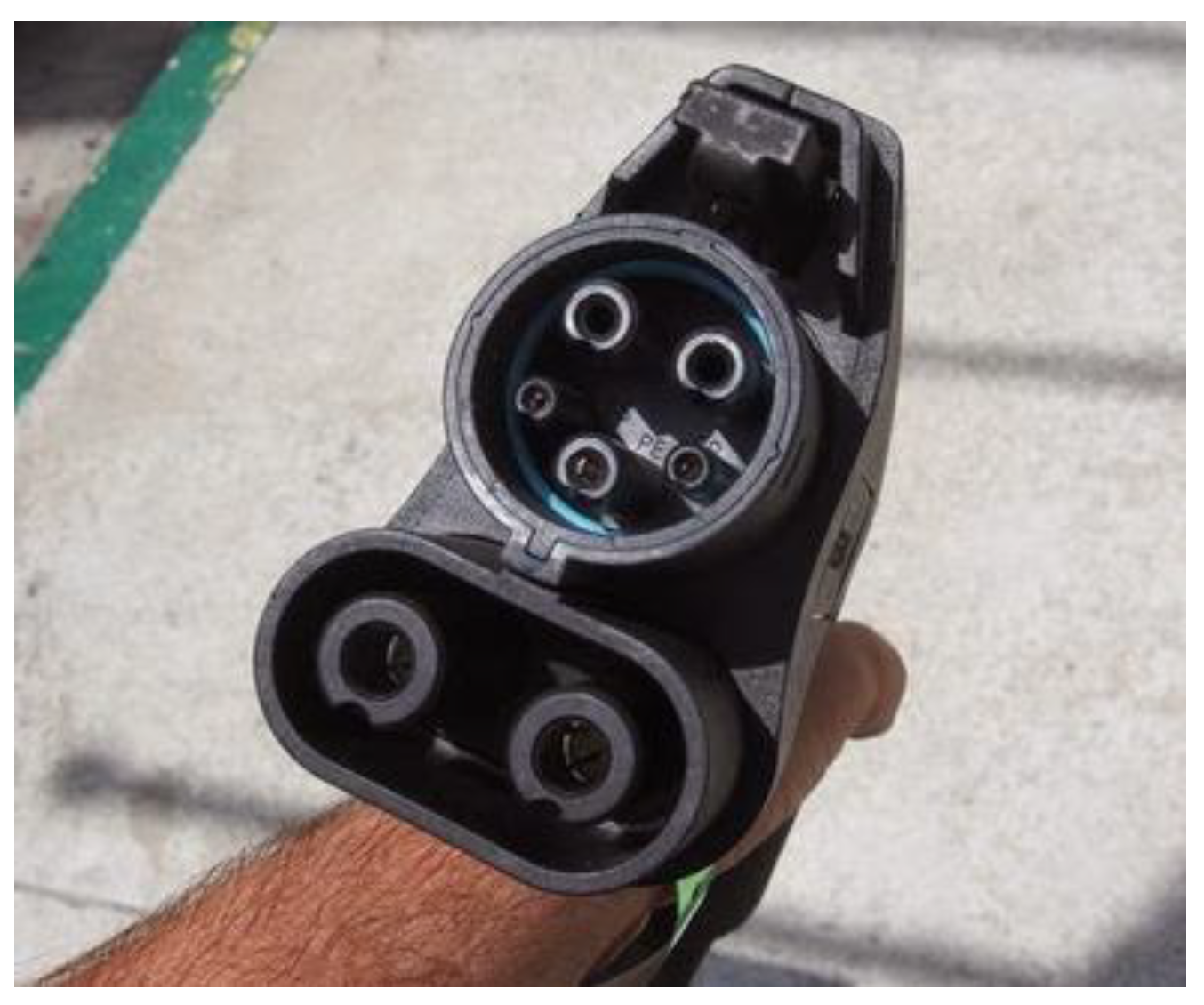
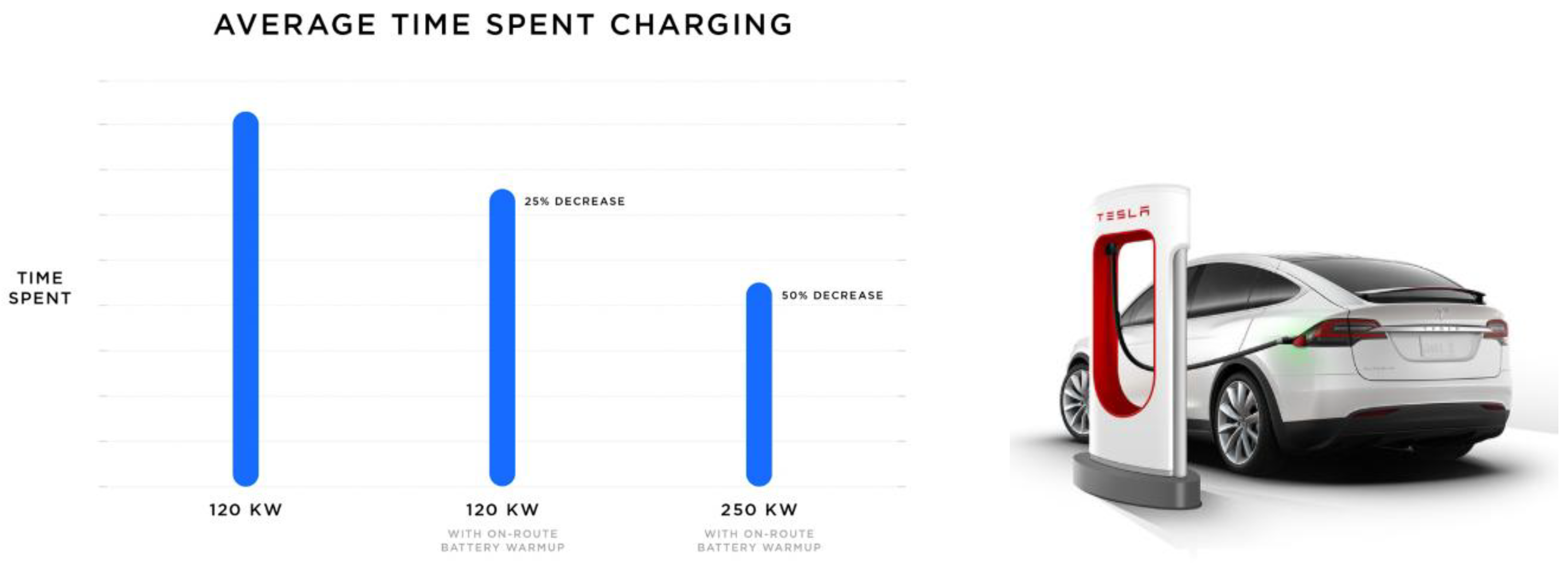
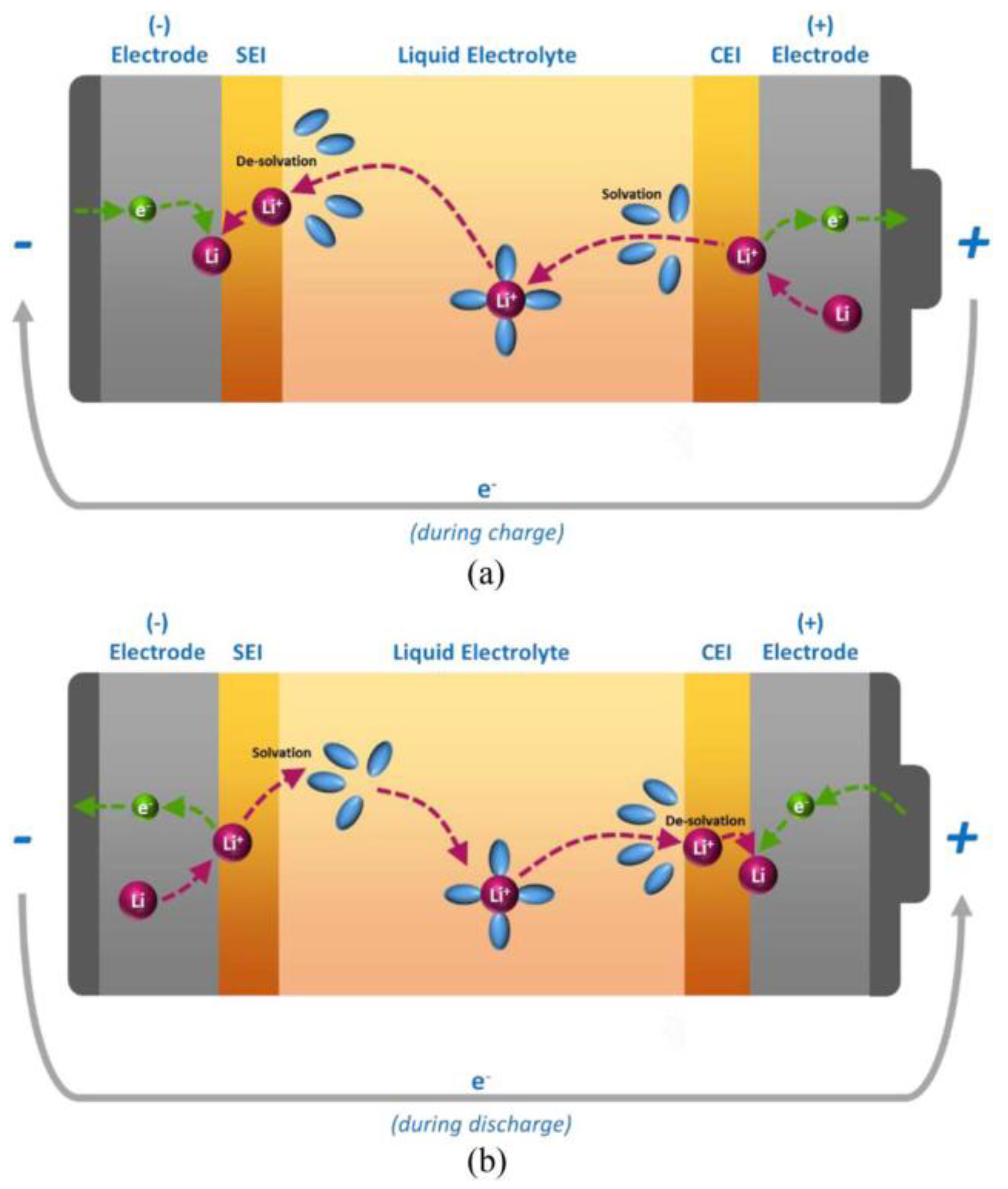
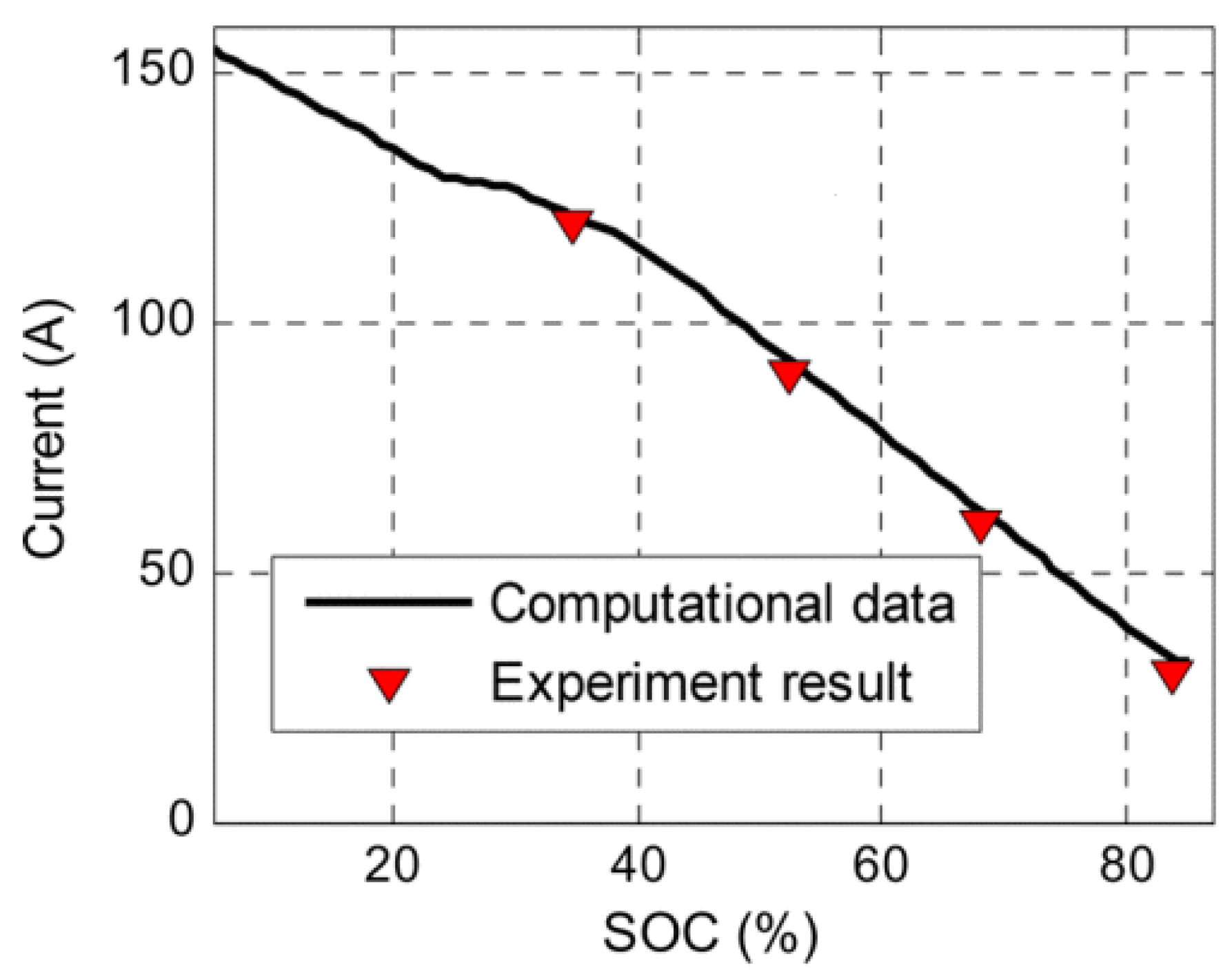
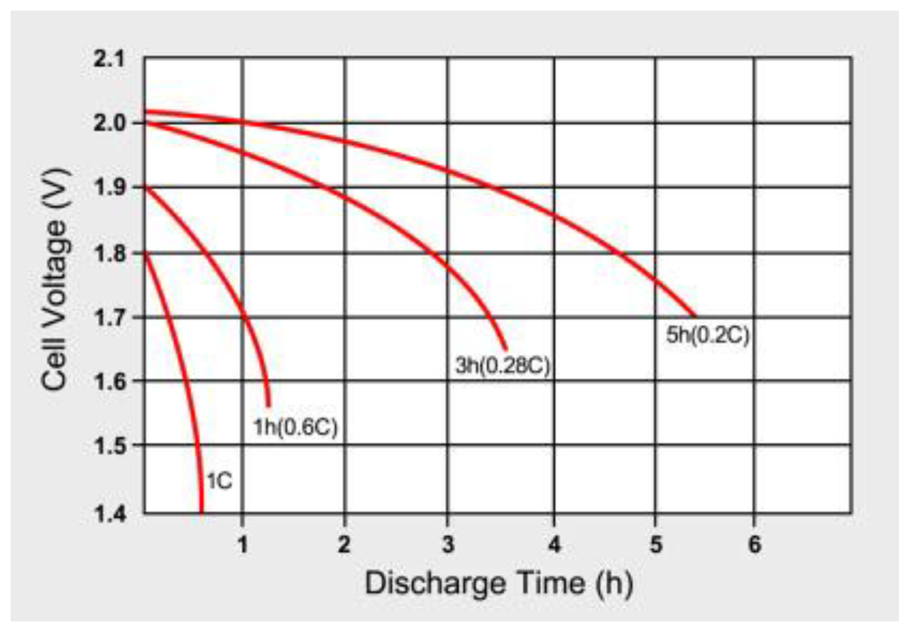
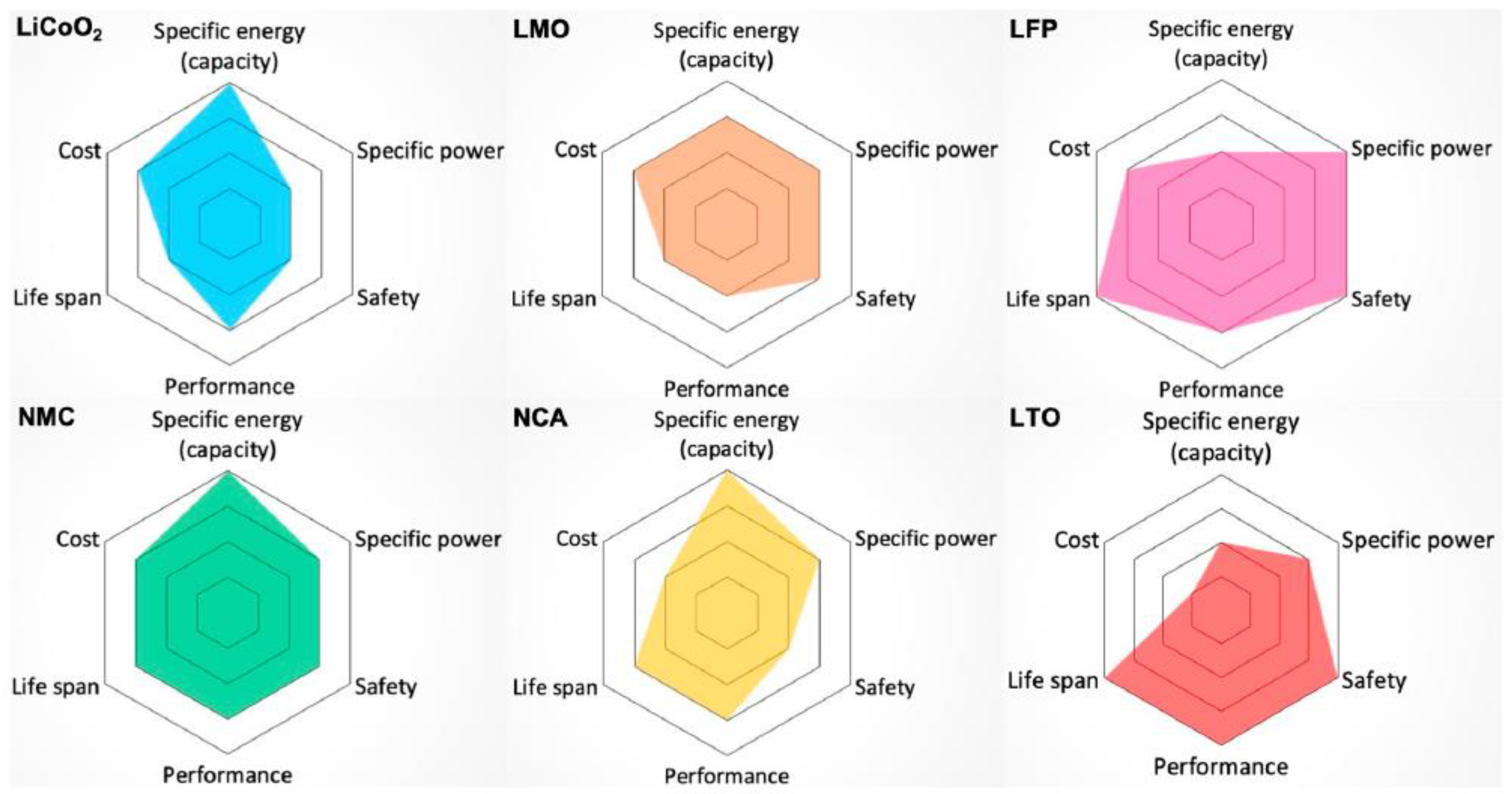
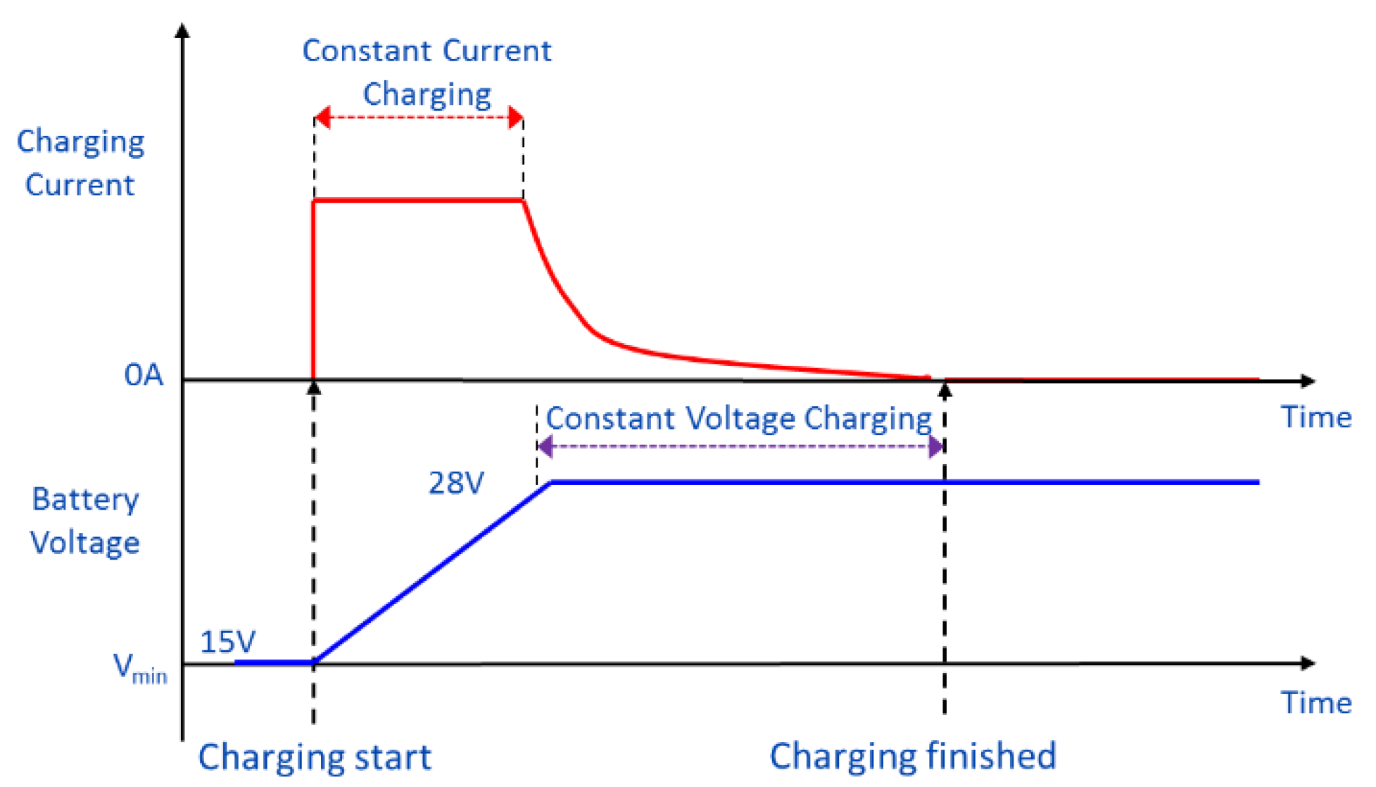
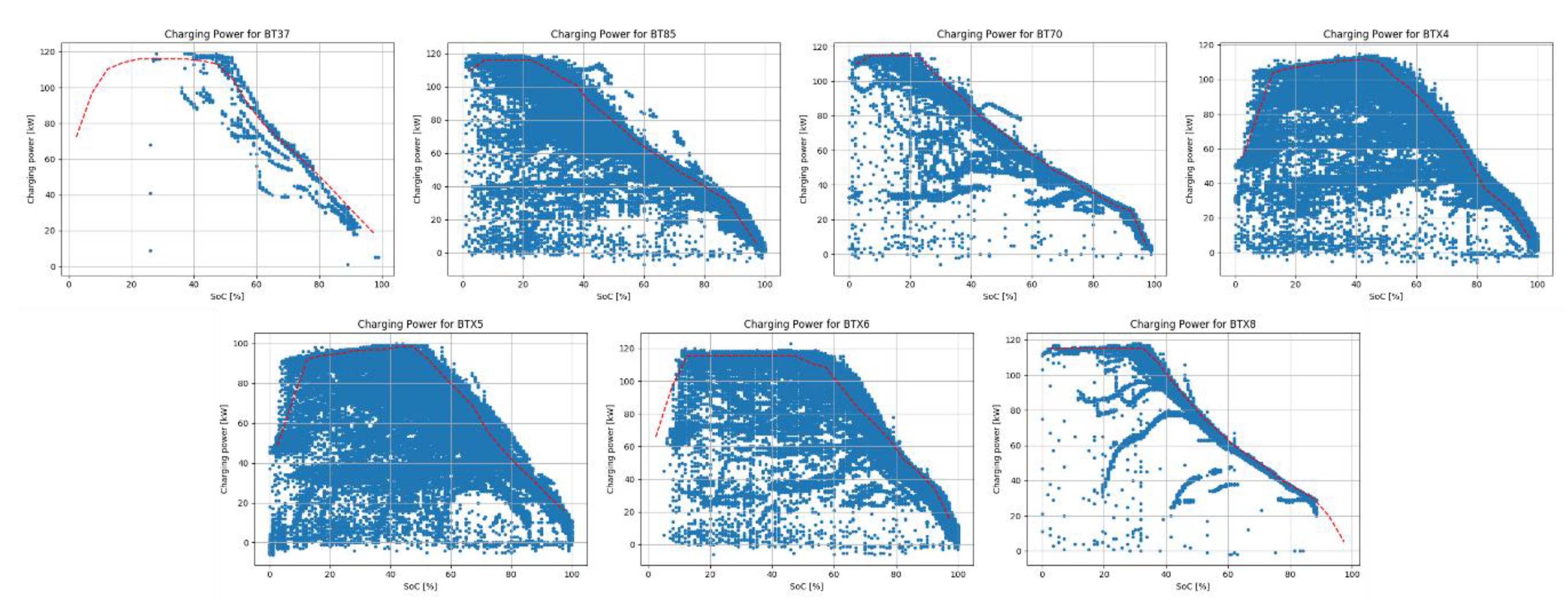
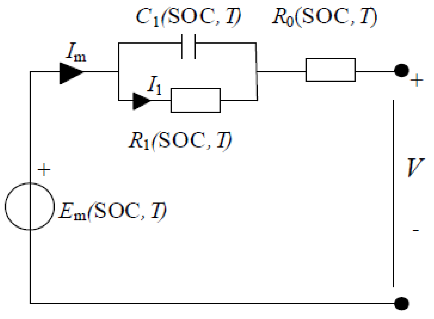
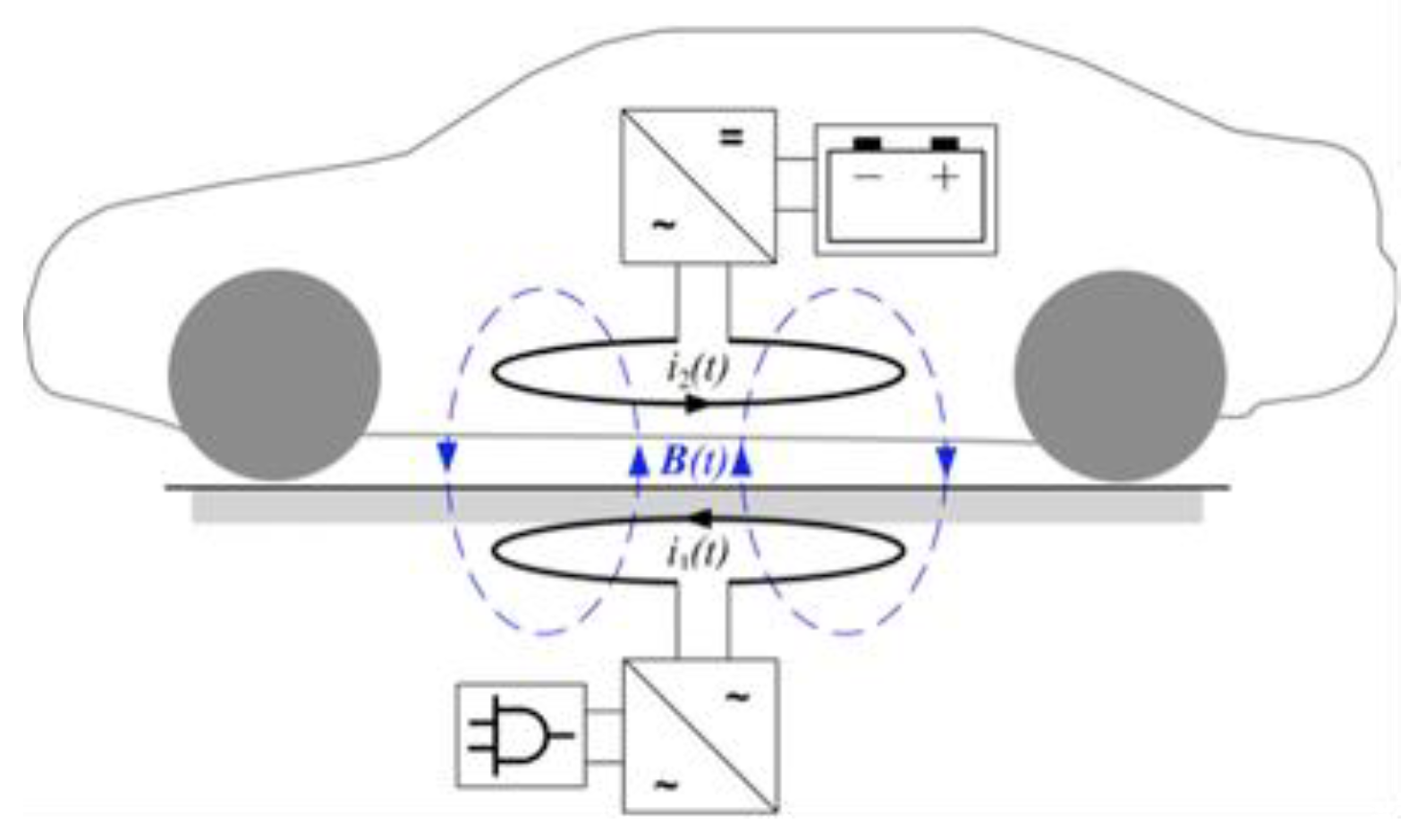
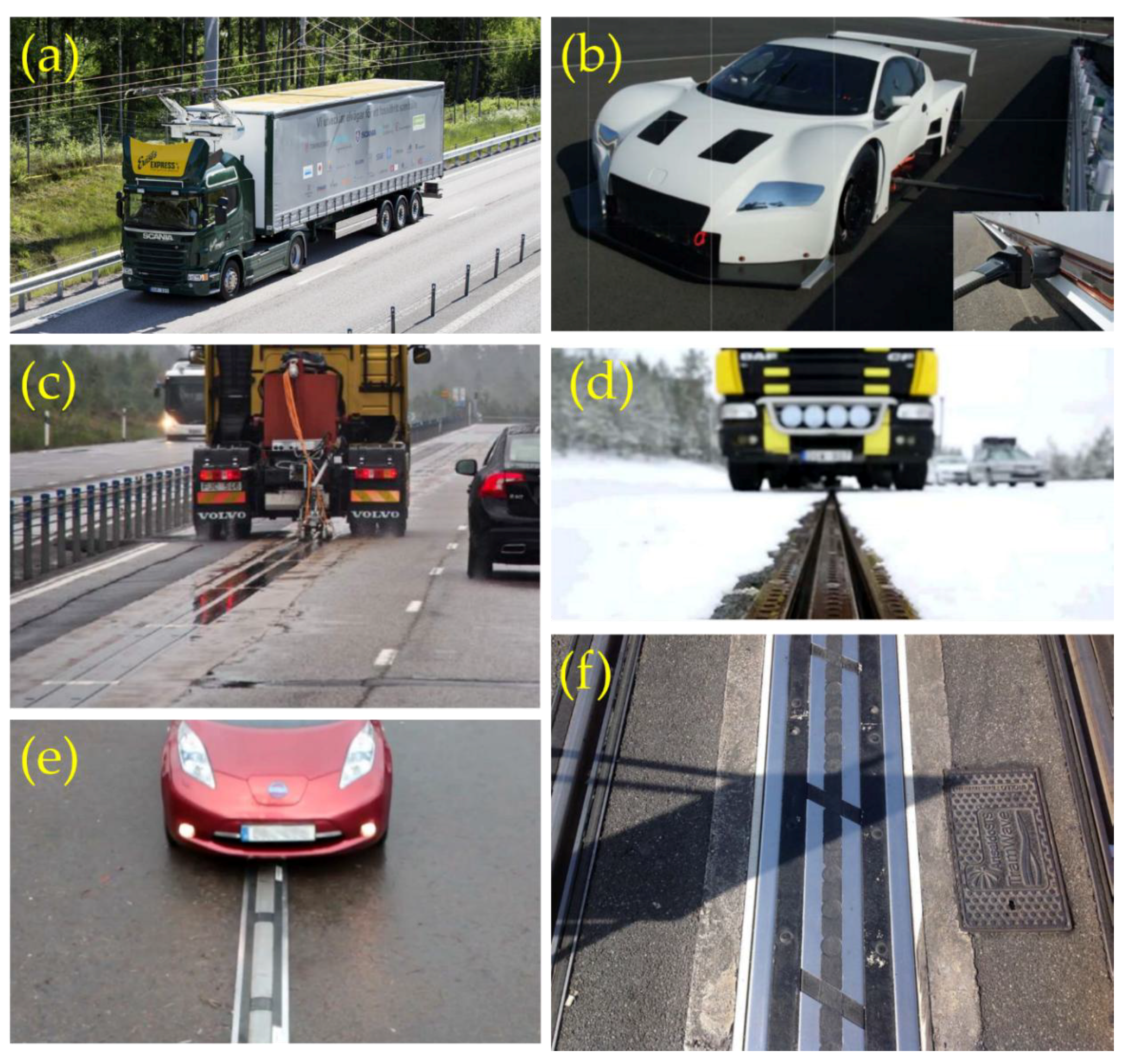
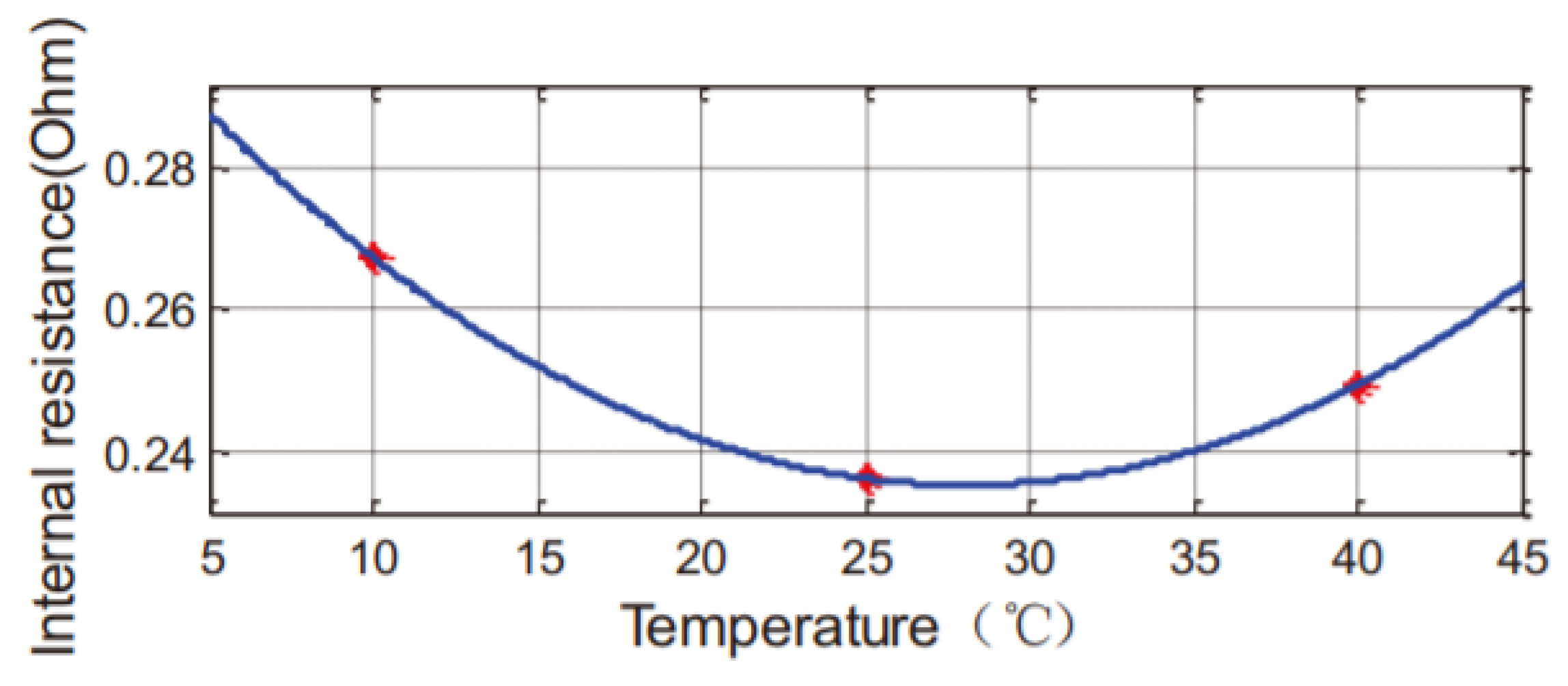
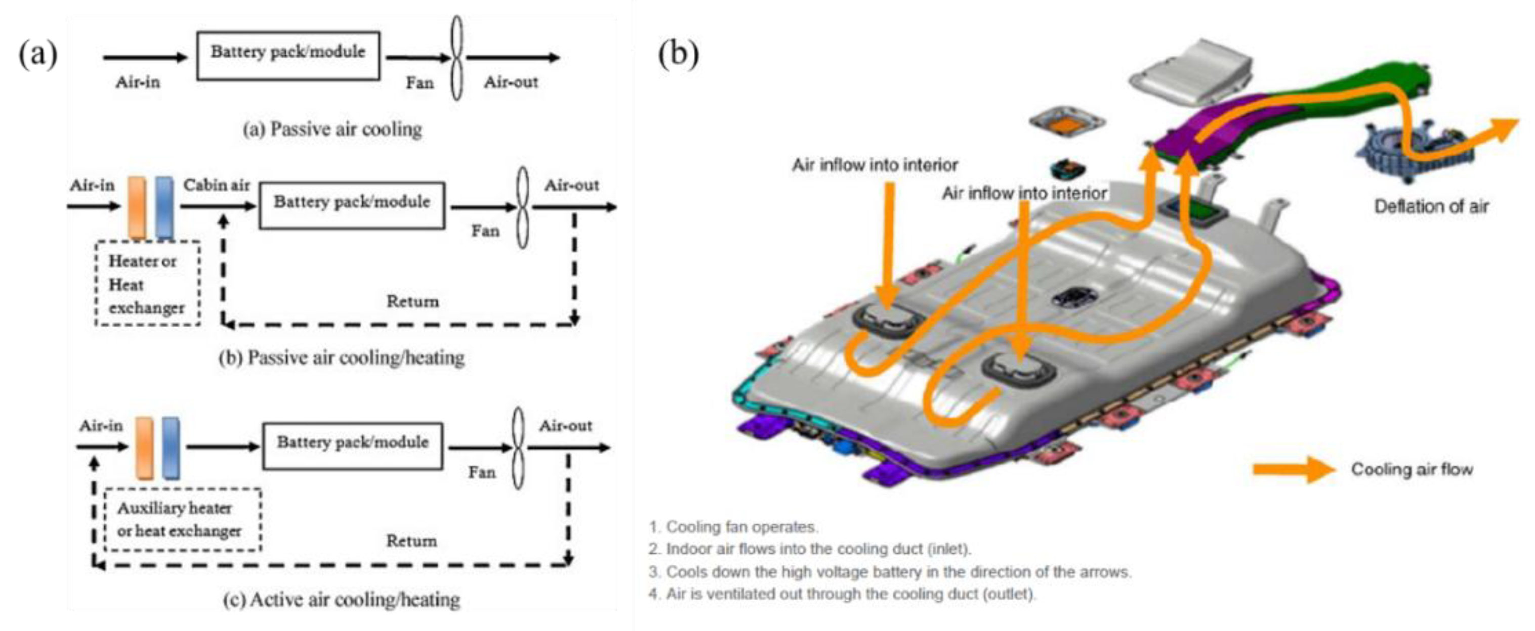
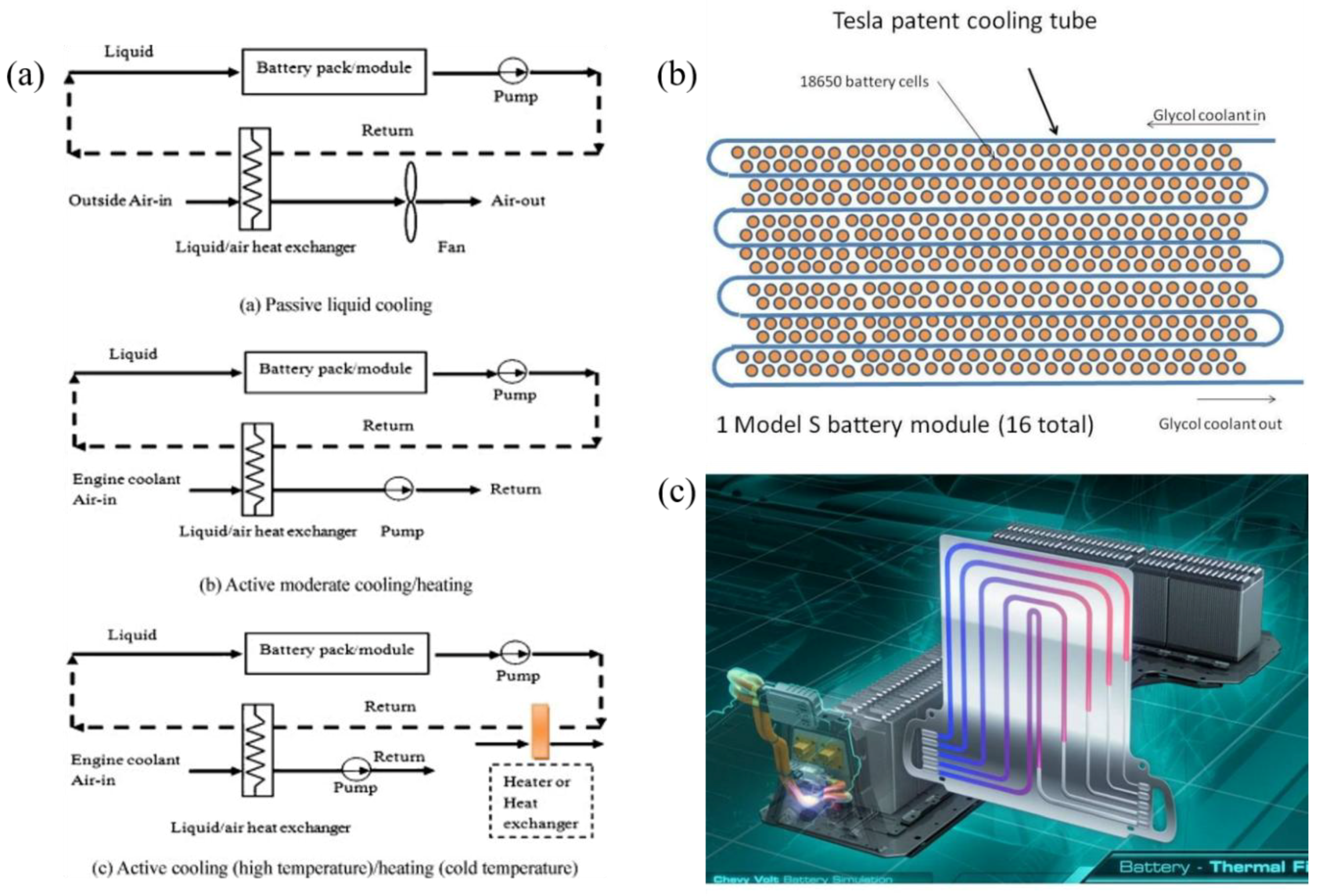
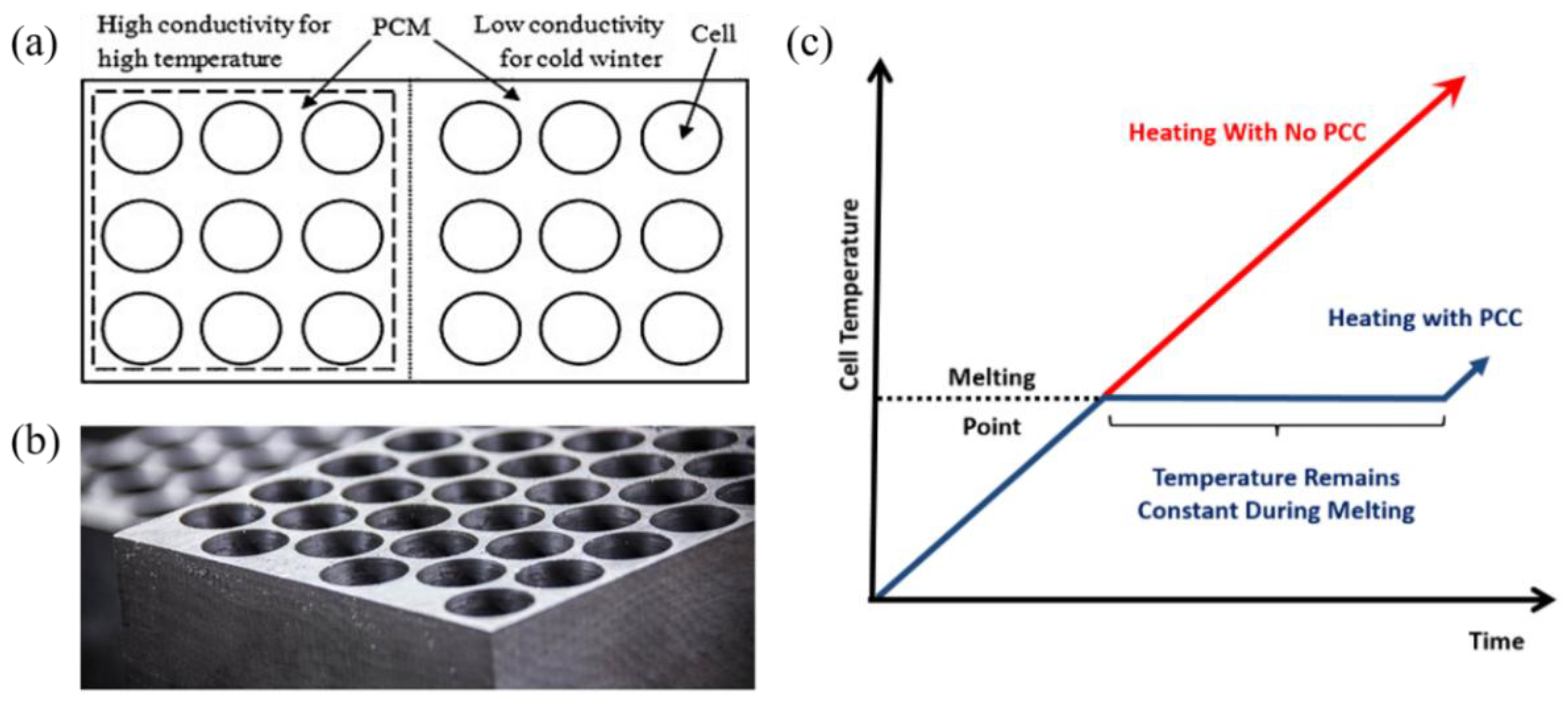
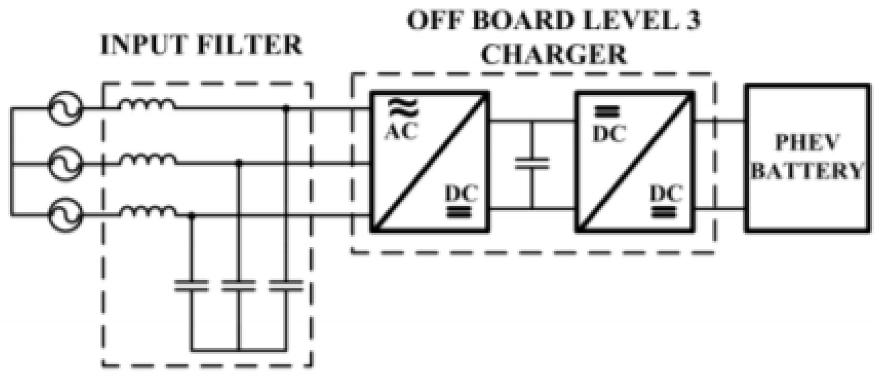
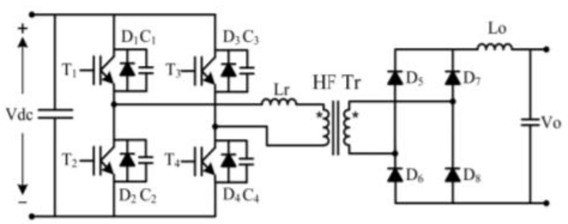
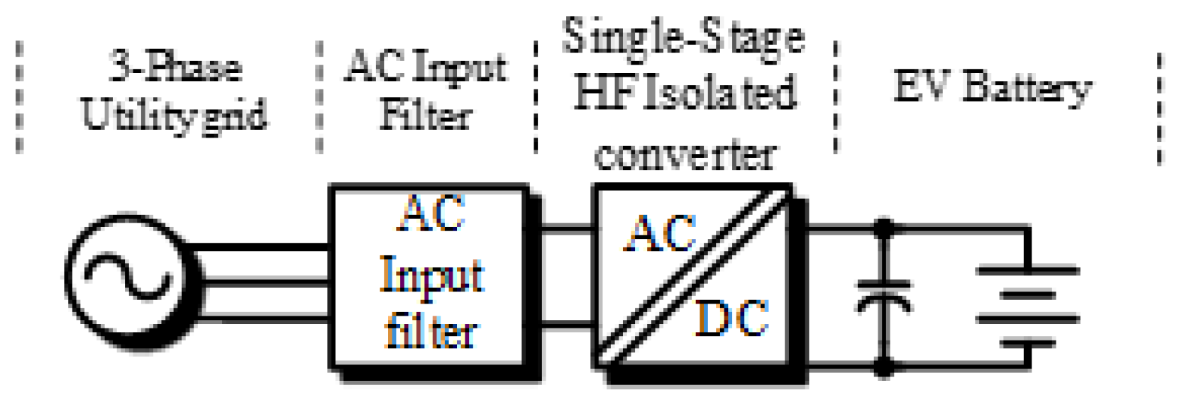
Table 1.
C-rate and service times when charging and discharging batteries of 1Ah [31].
Table 1.
C-rate and service times when charging and discharging batteries of 1Ah [31].
| C-rate | Time |
|---|---|
| 5C | 12 min |
| 2C | 30 min |
| 1C | 1 h |
| 0.5C | 2 h |
| 0.2C | 5 h |
| 0.1C | 10 h |
| 0.05C | 20 h |
Table 2.
A list of Tesla batteries used for the real-world data collection [40].
Table 2.
A list of Tesla batteries used for the real-world data collection [40].
| Battery Code | Tesla Model | Estimated Usable Capacity (kWh) | 10 kWh → 50 kWh Charge Time (min) |
|---|---|---|---|
| BT37 | 3 Long Range | 72.8 | 23 |
| BT70 | S70 | 65.7 | 33 |
| BT85 | S85 | 73.4 | 27 |
| BTX4 | S/X90 | 79.8 | 23 |
| BTX5 | S/X75 | 71.6 | 27 |
| BTX6 | S/X100 | 95.7 | 20 |
| BTX8 | Rare S/X75 | 25 |
© 2019 by the authors. Licensee MDPI, Basel, Switzerland. This article is an open access article distributed under the terms and conditions of the Creative Commons Attribution (CC BY) license (http://creativecommons.org/licenses/by/4.0/).
Share and Cite
MDPI and ACS Style
Collin, R.; Miao, Y.; Yokochi, A.; Enjeti, P.; von Jouanne, A. Advanced Electric Vehicle Fast-Charging Technologies. Energies 2019, 12, 1839. https://0-doi-org.brum.beds.ac.uk/10.3390/en12101839
AMA Style
Collin R, Miao Y, Yokochi A, Enjeti P, von Jouanne A. Advanced Electric Vehicle Fast-Charging Technologies. Energies. 2019; 12(10):1839. https://0-doi-org.brum.beds.ac.uk/10.3390/en12101839
Chicago/Turabian StyleCollin, Ryan, Yu Miao, Alex Yokochi, Prasad Enjeti, and Annette von Jouanne. 2019. "Advanced Electric Vehicle Fast-Charging Technologies" Energies 12, no. 10: 1839. https://0-doi-org.brum.beds.ac.uk/10.3390/en12101839
Note that from the first issue of 2016, this journal uses article numbers instead of page numbers. See further details here.