Recent Advances in Transcritical CO2 (R744) Heat Pump System: A Review

1
College of Engineering, North Dakota State University, Fargo, ND 58108, USA
2
Architectural Engineering and Construction Science, Kansas State University, Manhattan, KS 66506, USA
*
Author to whom correspondence should be addressed.
Energies 2019, 12(3), 457; https://0-doi-org.brum.beds.ac.uk/10.3390/en12030457
Submission received: 7 January 2019
/
Revised: 23 January 2019
/
Accepted: 29 January 2019
/
Published: 31 January 2019
(This article belongs to the Special Issue Low Carbon and Resilient Planning, Design, and Construction of the Built Environment: Mitigation and Adaptation Achievements and Future Directions)
Abstract
:Heat pump (HP) is one of the most energy efficient tools for address heating and possibly cooling needs in buildings. Growing environmental concerns over conventional HP refrigerants, chlorofluorocarbons (CFCs), and hydrofluorocarbons (HFCs) have forced legislators and researchers to look for alternatives. As such, carbon dioxide (R744/CO2) has come to light due to its low global warming potential (GWP) and zero ozone depleting characteristics. Even though CO2 is environmentally benign, the performance of CO2 HP has been of concern since its inception. To improve the performance of CO2 HP, research has been playing a pivotal role in developing functional designs of heat exchangers, expansion devices, and compressors to suit the CO2 transcritical cycle. Different CO2 HP cycles coupled with auxiliary components, hybrid systems, and refrigerant mixtures along with advanced control strategies have been applied and tested. This paper presents a complete overview of the most recent developments of transcritical CO2 HPs, their components, and applications.
1. Introduction
The natural refrigerant CO2 was one of the first refrigerants used in the mechanical refrigeration systems. Subsequently, synthetic refrigerants such as CFCs and HFCs took over due to their superior performance in heating and cooling applications. However, environmental concerns over using CFCs and HFCs have urged researchers to identify alternatives that are environmentally benign and can serve as an effective replacement to the conventionally used working fluids in the heat pumps (HPs) [1]. Additionally, the fluorocarbons are to be phased out, according to the Montreal Protocol [2]. Although there exist several natural refrigerants, not many meet the technical and safety requirements. For example, ammonia (R717, ASHRAE safety class B2) is toxic and flammable and, therefore, not suitable for several applications [3]. On the other hand, water (R718, ASHRAE safety class A1) is non-toxic [3]. However, due to its low density and low working pressure, it cannot serve as an ideal candidate for vapor compression refrigeration cycles [4]. Another drawback of water is that it has a very low heating coefficient of performance (COP) and is not cost-effective [5]. Table 1 represents a comparison of the properties of CO2 with some of the most commonly used refrigerants.
Among natural refrigerants, CO2 (ASHRAE safety class A1) is one of the few that is non-toxic and non-flammable [3] and can be released to the environment without the need to be recovered from any dismissed equipment. CO2 has very low GWP (i.e., 1) compared to other commercially available refrigerants. Moreover, CO2 has no regulatory liability since it has zero ozone depletion potential (ODP). The abundance of CO2 in the environment (0.04% of the atmospheric air) makes it cost-effective. Chemically, CO2 is an inert gas, and, according to ASHRAE 15 & 34 and ISO 5149 safety standards, CO2 is a safe refrigerant [3]. Therefore, there are minimal leakage concerns.
Additionally, the CO2 refrigerant facilitates the fabrication of lightweight HP systems for a given specific energy and pumping power due to its high fluid density and working pressure [6]. A high exothermal temperature glide in the gas cooler further enhances the heating performance of HP systems [7]. Likewise, the lower compression ratio of CO2 compared to fluorocarbons results in higher isentropic efficiency in a CO2 HP system [8]. Such advantages make CO2 an excellent candidate to serve as an effective replacement to the conventional working fluids like CFCs and HFCs. However, significant challenges of using CO2 are its low critical point (31.1 °C and 7.38 MPa) [6] and high operating pressure (8.0 to 11.0 MPa) [9], which require careful attention while designing the system components. The transcritical CO2 driven HPs have shown to have high irreversibility caused by throttling losses and superheated vapor horns, which results in low COP [7]. Due to these downsides, CO2 HP is not yet widely used. Despite this, research on CO2 HP systems has continued due to its high potential. Several works have improved the system’s basic components as well as auxiliary units such as internal heat exchanger (IHX). Moreover, research has shown promising improvements in CO2 HP for residential and commercial applications.
The objective of this review is to report on various technologies or approaches applied and tested on CO2 HPs. A comparison between conventional HP cycles with the transcritical cycles is provided to understand the applicability of CO2 in HP applications. The supercritical and two-phase heat transfer characteristics of CO2 in different heat exchanger (HX) configurations are briefly analyzed. Furthermore, recent modifications of each HP component and their impact on heating and cooling applications concerning different heat sources are detailed and discussed.
2. Comparison of Transcritical and Conventional Heat Pump Cycles
The transcritical cycle is thermodynamically different compared to a conventional vapor compression HP or refrigeration cycle. One of the distinct differences is in the heat rejection process. In the transcritical cycle, gas cooling takes place in the supercritical state while, in a vapor compression cycle, heat rejection takes place in the subcritical region through a phase change, which facilitates high-energy release. Consequently, the vapor compression cycle is commonly adopted in the HP and refrigeration industry. However, when CO2 is used in such a conventional subcritical cycle, the efficiencies are extremely low and are not cost effective. During the phase change, the amount of heat rejected by CO2 is significantly low since the heat rejection enthalpy decreases when condensation occurs near the critical point (31.1 °C, 7.38 MPa). However, if the CO2 vapor is compressed beyond the critical pressure, it can deliver much higher heat rejection enthalpy through sensible cooling. Therefore, the transcritical system regains efficiency.
In a CO2 transcritical HP cycle, the evaporator operates in the subcritical region while the gas cooler functions in the supercritical region. The pressure-enthalpy diagram (Figure 1) illustrates the difference between the conventional HP cycles and the transcritical HP cycles. In the transcritical cycles, heat absorption takes place below the critical temperature, and, hence, the pressure remains subcritical. Therefore, the evaporator functions similarly to heat the absorption process in a conventional vapor compression HP system. During the heat rejection process, the refrigerant changes its phase at a constant temperature in the subcritical cycles whereas, in the transcritical cycles, the refrigerant temperature decreases continuously throughout the heat rejection process without a phase change. Although latent heat exchange is an efficient heat transfer path, the supercritical properties of CO2 make it a viable candidate for transcritical HP systems. However, in a transcritical cycle, the pressure difference between heat absorption and heat rejection is much higher than a typical subcritical cycle, which results in significant thermodynamic losses in the expansion process. The large pressure difference makes it feasible to use expansion work recovery devices in a transcritical cycle, which can partially compensate for the throttling losses in the transcritical CO2 cycle [10]. In the compression process, the conventional subcritical cycle operates at a pressure ratio up to eight, whereas the transcritical cycle operates at a pressure ratio within the range of three to four [11]. Such low compression ratios are conducive for achieving high isentropic efficiency in an HP system.
3. CO2 Heat Pump Component Modifications
Performance of a CO2 HP depends on the components as a whole. However, individual component design and performance has an impact on the overall performance. Although the interdependency among the components does not allow for isolated improvement of each component, efforts need to be taken to improve the design of components and evaluate their contribution to the overall HP performance.
Exergy analysis (2nd law analysis) of the CO2 HP components can provide understanding on which a component is more sensitive for overall HP performance improvement. Yang et al. [13] employed an exergy analysis to identify the location and quantify irreversibility (exergy loss) in each component. They found that both the throttle valve and gas cooler contributed to a major irreversibility with each contributing a maximum of 38% followed by the compressor, which recorded 35% of the total cycle irreversibility. Robinson et al. [14] carried out a similar study based on 2nd law analysis and reported that the expansion valve had the highest exergy loss followed by the compressor, the gas cooler, and the evaporator.
In contrast, Sarker et al. [15] and Bai et al. [16] found that the maximum exergy loss occurred at the compressor followed by the gas cooler/the evaporator. Similarly, Ghazizade-Ahsaee et al. [17] reported that the most exergy destruction happened in the compressor and the other components had a relatively low exergy destruction rate.
Hence, the HP system’s performance can be improved through appropriate component design to reduce the losses. This section details the recent advances in key components of CO2 HP, and, subsequently, the major findings are summarized in Table 2.
3.1. Gas Cooler
In a transcritical CO2 HP, the heat rejection takes place at the supercritical temperature and pressure, and the optimum COP of the system is contingent upon the supercritical properties of CO2 at the gas cooler [34]. A significant number of experimental and numerical studies can be found in the literature that has analyzed the supercritical CO2 (scCO2) heat transfer characteristics in different types of channel geometries and arrangements. Since Cabeza et al. [35] have performed a comprehensive review of scCO2 heat transfer for many applications, several selected, recent studies on the scCO2 heat transfer mechanism in different HX configurations specifically for HP applications are presented. Additionally, different types of HX as a gas cooler and their effect on HP performance are analyzed in this section.
Liao et al. [36] experimentally analyzed the heat transfer performance of scCO2 in a horizontal and inclined straight tube. The results showed that the heat transfer coefficient (HTC) was at the peak near the pseudo-critical region due to the enhanced specific heat capacity of CO2. Moreover, the HTC increased when the bulk temperature was higher than the critical temperature for horizontal and vertical flow. The effect of buoyancy was more prominent in large diameter tubes than in mini-tubes, which caused a reduction in the scCO2 Nusselt number in a mini-channel, and, subsequently, a new Nusselt number correlation was proposed based on the experimental results. In a similar study, Dang et al. [37] suggested a modification of the Gnielinski correlation to predict the HTC of scCO2 in a circular, straight tube considering the effects of mass flux, heat flux, and tube diameter on HTC. They found that an increase in mass flux enhances the scCO2 HTC, but the effects of heat flux and tube diameter depend on the scCO2 property variation in a radial direction. Studies on horizontally circular tube-in-tube HXs showed that the HTC of scCO2 is a combination of free and forced convection because of the buoyancy effect close to the pseudo-critical vicinity [38,39,40].
Helically coiled tubes HX were found to enhance scCO2 HTC compared to straight tubes HX [41,42]. In helical structures, the centrifugal and buoyancy forces affect the flow field and heat transfer. The effect of buoyancy force can be ignored if the buoyancy number (Bo) is below 5.6 × 10⁻⁷ [43]. Liu et al. [44] numerically analyzed the effects of buoyancy and the centrifugal force on the HTC of scCO2 in horizontal and inclined helically coiled tubes for Bo > 5.6 × 10⁻⁷. The HTC vacillates significantly due to a dominating buoyancy force compared to a centrifugal force when the CO2 bulk temperature is lower than the pseudo-critical temperature. Forooghi et al. [45] further explained the buoyancy induced supercritical heat transfer in vertical and inclined tubes. At a significantly low buoyancy number (Bo < 2.26 × 10⁻⁶), the heat transfer deteriorates due to low near-wall turbulence, and the heat transfer starts to increase with the increase of the buoyancy effect due to a velocity gradient rise between the outer tube wall and the centerline. In addition, the scCO2 HTC decreases with the increase in heat flux due to the reduced heat transfer capacity and thermal conductivity of CO2 [46]. However, increasing the CO2 mass flux in the supercritical region enhances the turbulence diffusivity and, as a result, improves the heat transfer performance and the effect of the turbulence Prandtl number on heat transfer is insignificant. Furthermore, a comparison demonstrated that the HTC in the inclined helical tube was higher than horizontally helical tubes due to the reduced centrifugal force and the dominating buoyancy force [47].
A simulation of a finned tube gas cooler indicated that the flow field characteristics and heat transfer depend on the fin configuration, and a slit fin has higher HTC than a continuous fin for both the air-side and refrigerant-side, which improves heat rejection [48]. Li et al. [49] developed a low-cost fin and micro-channel integrated gas cooler, where the fin and flat tube were integrated in a single aluminum plate to eliminate the contact resistance due to welding, which enhanced the HTC. They reported that the fin and micro-channel configuration could avoid air-side mal-distribution and had better performance at higher air velocities. Additionally, Garimella [50] and Chang et al. [34] proposed the use of near-counter-flow fin and tube type gas cooler.
Yang et al. [18] analyzed a multi-twisted-tube gas cooler where a counter-current double pipe copper HX was used as the gas cooler. In their HX configuration, the inner tubes were twisted together and fitted inside a larger tube. The theoretical and experimental results showed that a greater number of inner tubes increases the outlet water temperature, but, at the same time, the pressure drop increases sharply. Kim et al. [32] developed a multi-tube counter-flow gas cooler consisting of parallel smaller tubes bundled together inside a larger tube for a geothermal HP. In this configuration, the CO2 and water flow in the opposite direction to ensure maximum heat transfer.
Compactness of the gas cooler is another key focus of recent research, which can be achieved by reducing refrigerant charge and tube size, varying the air volume flow rate, and considering fin types. Marcinichen et al. [51] numerically studied these factors to reduce the size of an existing gas cooler used in a beverage vending machine. They found that the existing gas cooler was oversized by a factor of two, and a more compact design could be realized by increasing the air volumetric flow rate and replacing a plain fin with a wavy fin. In case of an undersized gas cooler, a ‘pinch point’ might occur due to the strong nonlinear variation of the specific heat capacity of CO2. A high value of pinch point indicates high thermal losses in the HX due to irreversibility. Chen et al. [52] analyzed the pinch point occurrence in a water-cooled CO2 HP using the log mean temperature difference (LMTD) method and found that the gas cooler was undersized by 30% to 40%. Likewise, Sánchez et al. [53] developed an accurate finite element model for properly sizing a CO2 gas cooler. Yin et al. [54] developed and studied a compact gas cooler model using a finite element approach where the micro-channel gas cooler consisted of three passes of 13, 11, and 10 tubes. They found an increasing number of passes in the gas cooler might improve the performance, but the three-pass design is the best since there is not much difference between a five-pass and a three-pass gas cooler concerning the exit CO2 enthalpy. Additionally, the simulations showed that using a multi-slab rather than a multi-pass could further reduce the gas cooler size due to improved performance of the gas cooler. Similarly, Tsamos et al. [55] carried out an experimental study on two different configurations of fin-tube gas cooler (two-row and three-row) considering both the supercritical and subcritical pressure at the HX. They found a linear relationship between the air temperature at the inlet and the pressure while transitioning from the subcritical to the supercritical stages. A simulation of the same fin-tube gas cooler showed that 90% of the pressure drop occurred in the first 17% of the HX length from the inlet [56], and the HX size could be reduced if the air flow rate is increased.
If the refrigerant mass flow rate is lower than the optimum amount, the degree of superheat (DSH) at the evaporator outlet increases, which causes an excessive pressure-drop, and, as a result, COP decreases. Conversely, if the refrigerant mass flow rate is excessive, the specific volume of the refrigerant at the compressor inlet increases, which causes a high pressure-drop at the evaporator and a low specific enthalpy change at the gas cooler. Therefore, for the same compressor power consumption, the specific enthalpy exchange becomes less, and the system COP decreases. As such, Liu et al. [57] developed a genetic algorithm for maximizing CO2 HP COP based on gas cooler pressure and the water flow rate. Similarly, to reduce the power consumption in real-time, Hu et al. [58] adopted an extremum seeking control (ESC) strategy considering the gas cooler pressure and outlet water temperature. A similar control strategy was developed by Peñarrocha et al. [59] to reduce the consumption by regulating the high-side pressure. by To optimize the performance of a CO2 refrigeration system, Kim et al. [60] suggested a new control strategy. They utilized the difference between the required total HTC in the gas cooler for optimum COP and total HTC at any concurrent gas cooler pressure. When the difference between the total HTCs is zero, the maximum COP is realized. However, this control strategy requires an exact value of total HTC at the gas cooler. Other than ESC, Ge et al. [61] proposed a heat recovery optimization system for a supermarket CO2 refrigeration system. The developed system used an opmimum gas cooler pressure to maximize heat recovery.
3.2. Evaporator
The CO2 HP evaporator functions like conventional CFC or HFC HP evaporators except that it experiences a much higher pressure (2–7 MPa) in the subcritical region. The CO2 evaporator operates at a reduced pressure higher than 0.36 at a saturation temperature of −10 °C whereas an R134a evaporator works below 0.10 at a saturation temperature of 10 °C [62]. Consequently, the transport properties of CO2 in the subcritical region (e.g., high vapor density and low vapor viscosity) are substantially different from the other refrigerants. The CO2 flow in the evaporator is characterized by two-phase flow, and the transport properties drastically influence the nucleate boiling, the convective heat transfer, and the CO2 pressure drop in the flow. Recent numerical and experimental studies focus on improving the efficiency of CO2 evaporator considering the flow characteristics. To ensure the feasibility of a CO2 HP, it is essential to design the evaporator as a compact, lightweight, and reliable system [63].
The CO2 two-phase heat transfer in macro-channels and micro-channels depends on the refrigerant mass flux, heat flux, channel geometry, and saturation temperature [62]. In an investigation of CO2 two-phase heat transfer and pressure characteristics in a conventional macro-channel, Yoon et al. [64] reported that CO2 boiling HTC increased with the increase in heat flux at the low vapor quality but decreased with the increase in heat flux when the vapor quality was above a specific value. This can be explained by the inception of vapor dryout at a high vapor quality due to an increase in heat flux, low surface tension, and reduced viscosity. The pressure drop was found to increase with an increase in mass flux, while there was an opposite trend for increasing the saturation temperature. Bredesen et al. [65] and Knudsen et al. [66] found in their experimental studies that the two-phase heat transfer in large tubes could be enhanced significantly by increasing the heat flux without a considerable pressure drop.
From the perspective of the physical aspect, a microchannel and minichannel HXs as the CO2 evaporators rather than macro HXs have been the recent research focus due to enhanced HTC, minimized leakage, and reduced refrigerant charge. Choi et al. [67] investigated CO2 two-phase heat transfer in horizontal mini-channels and reported that CO2 HTC increases with an increase in vapor quality. Moreover, CO2 HTC was found to be three times higher than R143a. Based on their experimental study, they proposed a separate two-phase flow heat transfer model for CO2 flowing in smooth mini-channles. Oh et al. [68] experimentally studied five different refrigerants in mini-channels and found that CO2 has the highest boiling HTC. Wu et al. [69] and Yun et al. [70] further reported that the nucleate boiling is predominant at a lower vapor quality because the heat flux and saturation temperature dictate the local HTC in this region, while the convective HTC dominates due to a high vapor velocity at a higher vapor quality. The pressure drop across the mini-channel was evaluated in Reference [69] by modifying a frictional factor developed by Cheng et al. [71] to address the overprediction of a frictional pressure drop in the mist flow region.
Concerning the evaporator configuration, several types of CO2 HXs have been studied. In a study of an electric vehicle HP system in a cold climate, Wang et al. [72] found that the micro-channel evaporator had less than 4% exergy loss in all operating conditions. Yun et al. [22] simulated a three-slabbed micro-channel evaporator using R134a and CO2 as the working fluid and compared their performance. The numerical results showed that the overall system performance could be enhanced by increasing the two-phase flow region in the micro-channel. There was a 70% increase in the two-phase flow region when the fin spacing was manipulated from 1.5 to 2.0 mm, and such a marginal increase in the spacing not only reduced material cost but also helped to eradicate the defrosting and condensation drainage problem. Furthermore, the selection of an appropriate circuiting arrangement is found to be imperative to ensure a higher heat transfer in a CO2 evaporator. Bendaoud et al. [73] developed a new model accounting for the thermal and hydrodynamic behavior of a fin and tube HX. The developed tool was used to study a typical CO2 evaporator coil consisting of two circuits in a parallel counter-current configuration. The study showed that the pressure drop was very low for CO2 compared to other refrigerants, and, as a result, the temperature glide was limited considerably. In another study, Yamaguchi et al. [21] experimentally and numerically studied a cross-fin tube HX with smooth plate fins as a CO2 evaporator for the water heating application, and the results confirmed that the heat exchange rate in the evaporator decreased (20 to 12 kW) with a rise in inlet water temperature (8 to 44 °C). Yun et al. [22] compared a two-slabbed micro-channel evaporator and a conventional round fin-tube HX for a CO2 system, and they found that the micro-channel evaporator aided a 33% increase in performance compared to the round fin tube HX. This was attributed to the larger effective surface area, especially with a V-shaped (Figure 2) micro-channel HX (MCHX) yielding a higher HTC.
Moreover, the addition of a flash gas bypass (FGB) in an HP cycle can improve evaporator performance [74]. In this technique, the refrigerant passes through a throttling device and expands to the evaporator pressure. The low-pressure refrigerant then goes to a flash tank where only a saturated liquid refrigerant enters the evaporator while the vapor bypasses the evaporator. Thus, the pressure drop in the evaporator can be minimized and, thereby, the flow distribution can be improved. Elbel et al. [23] showed that using FGB for a CO2 micro-channel evaporator could improve heat transfer and COP by 9% and 7%, respectively. However, a lack of complete separation in the flash tank can have a detrimental effect on the system performance [75].
3.3. Compressor
Compressor converts the low-pressure refrigerant to the required high-pressure condition. To attain the CO2 supercritical pressure at the gas cooler, a CO2 HP operates at a much higher compressor discharge pressure (CDP) (90–130 bar) compared to CFC/HFC HPs (10–40 bar). Such high CDP in a CO2 HP can result in a significant mechanical loss as well as oil leakage. Different compression mechanisms (e.g., reciprocating, rotary, and scroll) have been studied in terms of the compressor’s performance and reliability.
Jiang et al. [25] studied a reciprocating compressor manufactured by the Dorin Company to analyze the impact of different compression cycles with and without IHX. The results confirmed that the CDP, which was affected by the gas cooler outlet temperature, was always higher than the critical pressure of CO2 (7.377 MPa), irrespective of the IHX use. However, an IHX between the gas cooler and the compressor resulted in a CDP increase of 0.2 to 0.4 MPa. Additionally, the Mitsubishi Company recently developed a commercial CO2 compressor with a single rotary mechanism exclusively targeting residential HP applications [76]. The design mainly focused on the reduction of a leakage path and the optimization of oil supply to the compressor. The study showed that the system performance improved (COP = 4.5) by minimizing the radial clearance and optimizing the oil supply (0.1% of oil exhalation) to the compression chamber. In another study, Hiwata et al. [27] carried out a detailed study on a single-stage scroll compressor and compared its performance with their in-house built, two-stage rotary compressor. They reported that the scroll compressor performed with an average COP ratio of 1.05, which is marginally better when compared to the rotary compressor. Such an increase in compression efficiency was achieved by adjusting the oil-injection rate in the compression chamber. Shimoji et al. [77] developed a prototype CO2 scroll compressor for air conditioning based on R410A compressors and analyzed its basic quantitative losses through a simplified model. They found the volumetric and overall adiabatic efficiency reduced by 17% and 16%, respectively, while dropping rotational speed from 3600 to 1800 RPM.
In terms of system configuration, the hermetic and semi-hermetic types are the recent research focus. In a study of a semi-hermetic compressor integrated with a recuperative HX. Rozhentsev and Wang [26] reported that the HP performance was sensitive to even a marginal change in compressor efficiency and CDP (Figure 3). For example, at an optimum discharge pressure (85 bar), when the compressor efficiency decreased from 1 to 0.75, the overall HP performance reduced by 30% from the maximum COP of 4.5. However, they found the internal superheating had a minimal impact on the HP COP. Cavallini et al. [78] optimized a two-stage transcritical cycle using a semi-hermetic reciprocating compressor coupled with an intercooler. They reported the split-cycle with an integrated suction line HX could increase the COP up to 25% compared to a baseline two-stage cycle. Zhang et al. [79] experimentally compared the performance of a rolling piston hermetic configuration in single and two-stage compressors. They found that the volumetric efficiency of the single-stage compressor was higher than that of two-stage at compression ratios below 2.8, but the two-stage showed a higher volumetric efficiency at a compression ratio of 2.8 or higher. The isentropic efficiency had the same trend as volumetric efficiency. However, the DSH had a minimal effect on both volumetric and isentropic efficiencies for both configurations.
Recent studies have shown that, from a thermodynamics point of view, it is favorable to use a two-stage compressor in a transcritical CO2 HP due to a high working pressure. Cecchinato et al. [80] found a 70% increase in energy efficiency could be achieved using a two-stage double-throttling system compared to a simple single-stage single-throttling system for a severe evaporating temperature of −30 °C. Moreover, the two-stage system with an injection throttling outperformed the system with an IHX in term of COP and heating capacity. Similarly, for water heating applications, Pitarch et al. [81] reported that the COP of the two-stage system was 11% higher than the single stage system. A commercially developed two-stage compressor for residential CO2 HP water heaters equipped with an intermediate gas-injection mechanism between the first and second stages helped to reduce the vapor mixture losses [76]. It was found that such a two-stage configuration improved the compressor performance by 15% and 30% for compression ratios of 3 and 4, respectively. In another study, Cho et al. [82] found that, in a two-stage refrigeration cycle, integration of gas injection could increase the cooling COP by up to 17% compared to a non-injection cycle. Similar to the two-stage design, Xing et al. [29] combined a high-pressure compressor and a low-pressure compressor using an IHX, and the simulation showed that the new design could attain 10% to 30% higher COP compared to a baseline system at a given evaporating temperature of −15 °C. Based on six different configurations of two-stage CO2 refrigeration systems, Liu et al. [83] found that the gas cooler outlet temperature and the low-stage compressor significantly affect the system performance.
Recently, the BoostHEAT Company introduced a new and original concept of a thermal compressor for transcritical CO2 HP. Unlike the rotary or scroll compressors where the mechanical power generates the pressure increase of working fluid, in the new design, a heater provides thermal energy to warm up the working fluid of the compressor and then to increase its pressure. The uniqueness of the system is that the same working fluid can be used in both the thermal engine and the HP to enhance thermal efficiency. To analyze the thermal performance of the compressor, Ibsaine et al. [84] formulated a mathematical model and recommended that a two-stage thermal compressor is preferred in CO2 HP applications.
3.4. Expansion Device
The prime functions of the expansion device in a CO2 HP are to distribute CO2 to the evaporator as well as to maintain a pressure difference between the evaporator and the gas cooler. Most of the recent investigations focused on different kinds of expansion device designs (e.g., ejectors, expansion valves) and their configurations in terms of the numerical modeling, geometrical structure, and system performance enhancement.
Theoretical and experimental investigations suggest that an ejector in place of an expansion valve can improve transcritical cycle performance [85,86,87]. The refrigerant inside the ejector is characterized by two-phase and compressible flow. A homogeneous equilibrium model (HEM) and homogeneous relaxation model (HRM) are the two widely used numerical models for the ejector flow [88]. HEM considers liquid and vapor phases are in a homogeneous equilibrium whereas HRM uses the empirical correlation of the relaxation time. Lucas et al. [89] and Palacz et al. [90] employed HEM to predict the two-phase flow inside an ejector. The HEM accuracy decreases with a decline in a motive nozzle temperature and increases in deviation from the saturation line, which demands a more complex HRM mode. Angielczyk et al. [91] studied HRM for a supersonic flow through the convergent-divergent nozzle of a CO2 ejector and validated their model using three different nozzle diameters. They developed a widely excepted correlation for relaxation time considering the critical flow parameters, vapor quality, and temperature profile. Through a comparison study, Palacz et al. [92] found that HRM could predict the flow characteristics better than HEM (overall a 5% increase in accuracy). In addition, Zheng et al. [93] and He et al. [94] proposed dynamic numerical models, which are useful in predicting the dynamic system response in different operating conditions to optimize the ejector expansion performance.
In a CO2 transcritical cycle, expansion or throttling losses result in a low system performance. Such throttling losses can be overcome by adopting multi-ejector systems (connected in parallel or in a different combination). A study on a two-ejector system has shown that throttling losses could be substantially reduced, and the heating COP could be increased by about 10% to 30% compared to the basic two-stage cycle with a flash tank [29]. Furthermore, Boccardi et al. [30] experimentally studied the benefit of integrating a multi-ejector in a transcritical CO2 cycle for heating applications. They found that the optimal multi-ejector configuration could reduce the throttling losses by 46%, and, thereby, improve the system performance by up to 30%. Bai et al. [95] utilized two cascaded ejectors in a dual temperature transcritical CO2 system, which outperformed the basic system without the ejector. Additionally, the exergy efficiency and COP of the cascaded ejector system increased up to 25% and 28%, respectively, when compared to a single ejector system due to a higher pressure lift and better pre-compression. In another study, Bodys et al. [96] introduced swirl motions at the inlet of the motive and suction nozzle of fixed ejectors of a CO2 multi-ejector system. Swirl motion enhances the momentum exchange in the mixing section of the ejector and, thus, increases the contact time between the primary and secondary flow stream. They found that the system performed better due to the swirl motion at the inlet of the motive nozzle, but the swirl motion at the suction nozzle did not have any impact on the performance. Figure 4 shows the variation in ejector efficiency with swirl RPM.
In addition, the adjustable ejector configuration was found to enhance the system COP up to 30% compared to the fix-geometry ejector [97]. This was attributed to the fact that the adjustable ejector can provide a flexible control over the mass flow rate, which is the key to performance improvement. Lie et al. [98] performed a study to analyze the performance of an adjustable ejector for a simultaneous heating and cooling application. They found that an optimum heating and cooling performance can be achieved by regulating the ejectors’ internal geometries. Xu et al. [99] made an effort to optimize the high-side pressure through an adjustable ejector (Figure 5), which uses a stepper motor moving a needle forward and backward to adjust the nozzle throat area. The study showed that such an ejector could regulate the throttling area for an optimal high-side pressure. The optimized pressure has a positive effect on the system performance and outweighs the low ejector efficiency. Additionally, Xu et al. [99] developed a control strategy to maximize the COP by correlating the CO2 pressure and temperature at the gas cooler exit. A multi-variable adjustable ejector controller [100] and an on-line quasi-cascade controller [101] are among the other control systems for optimizing the performance of adjustable ejectors. For the later one, the nozzle throat area varies with the compressor speed and CO2 mass flow rate, so that a correlation for the optimum nozzle throat area can be derived for a gas cooler pressure based on the dynamic system response.
Among many types of expansion devices, the electronic expansion valve (EEV) and capillary tubes have been studied for CO2 HPs. Zhang et al. [102] experimentally studied the effect of the refrigerant charge amount and EEV opening on the performance of a CO2 HP water heater. The EEV opening of 40% was found to be optimal for their system. Increasing the EEV opening from its optimal value to 60% decreased the heating capacity up to 30% due to an increase in the refrigerant charge and supercritical pressure, but the undercharged condition had a more severe consequence on the performance than an overcharged condition. Baek et al. [9] investigated the control methods of the gas cooler pressure in a CO2 HP using an EEV. The EEV integrated CO2 HP showed enhanced COP due to optimized pressure in the gas cooler. Besides EEV, capillary tubes are preferred as an expansion device particularly in small vapor compression refrigeration and air conditioning systems due to their simplicity, low initial cost, and low starting torque of compressor. However, flow characteristics inside the capillary tube under adiabatic condition are complex. Song et al. [103] found that the CO2 HP using a capillary tube is promising with its COP close to (above 80% of) that of a system using an EEV. In addition, in another study of CO2 HP, Madsen et al. [104] found that the use of an adiabatic capillary tube was better than a fixed high-pressure expansion valve but inferior to an adjustable expansion valve. The study recommended the use of a capillary tube in transcritical CO2 HP when the system is relatively small. Other than capillary tube, Hu et al. [105] studied and developed an improved design of a two-rolling piston expander for CO2 systems using sealing techniques to minimize the leakage.
3.5. An Auxiliary Component: Internal Heat Exchanger
As discussed in Section 3.3, studies have confirmed that single-stage compression is less efficient than the two-stage system. More commonly, an IHX has been installed to ensure better and efficient operation of the compression system [106]. Use of an IHX reduces the possibility of damaging the compressor when the liquid refrigerant exits from the evaporator and promotes the superheating of the vapor entering the compressor.
Xian et al. [29] modeled a high-performance two-stage CO2 HP using two ejectors and incorporated an IHX to the model. The researchers found that it could attain a 30% increase in the heating COP than a baseline two-stage HP at a standard operating temperature of −15 °C. Likewise, Kim et al. [32] developed a steady-state model to analyze the thermodynamic performance of an IHX in a geothermal CO2 HP, where a counter-flow multi-tube HX with several tubes encompassed in a larger tube was used as the IHX. They found that the system with IHX could achieve up to 6% increase in COP compared to the system without IHX at the 20% EEV opening. The proposed simulation program can serve as a useful tool for a thermodynamic performance analysis when optimizing complex system variables and establishing efficient operating conditions in CO2 geothermal HP systems. Similarly, Yamaguchi et al. [21] formulated a static mathematical model to study a CO2 HP with a twin-tube type HX as the IHX. They found that the addition of the IHX could enhance the COP up to 3.5 and had a positive influence on the heat transfer in both the gas cooler and evaporator. In a comparative study, Jiang et al. [25] utilized a double pipe copper HX as the IHX in which the high-pressure CO2 flew in the inner pipe and the low-pressure CO2 flew in between the inner and outer pipe. The experimental results demonstrated that, for a gas cooler temperature of 15 °C, the system with IHX had 6.5% to 11.5% higher COP than that of without IHX.
Shariatzadeh et al. [107] analyzed four different transcritical refrigeration cycles with and without IHX along with an expander and throttling device. They found the COP of the expander cycle is always higher than the throttling cycle due to the optimized gas cooler pressure and reduced exergy loss in the expander cycle. However, when the system worked in the expander cycle, use of an IHX reduces the average COP from 2.8 to 2.5 due exergy efficiency loss in the gas cooler, but, in case of the throttling cycle, integration of IHX reduces exergy loss and, as a result, increases the COP from 1.9 to 2.0. Zhang et al. [108] carried out a similar study and found that, when IHX is used in an expansion valve cycle, the system performance could increase by 17%. On the contrary, if IHX is used in an ejector cycle, the system performance degrades by 16%. This is attributed to a decrease in ejector isentropic efficiency with the integration of IHX.
In addition, the effects of IHX on system parameters rather than efficiency were studied. From an experimental investigation, Sánchez et al. [109] reported that the integration of IHX increases the compressor suction temperature, which reduces mass flow rate, and, as a result, specific compression work increases. However, this increase is very insignificant. Moreover, superheating induced by IHX increases the discharge temperature, and this effect is high at a low evaporating temperature. Pérez-García et al. [110] found the effectiveness of the IHX largely depends on the gas cooler outlet CO2 temperature, and the increased energy efficiency with the IHX is due to the subcooling of CO2. However, the mechanical subcooling system without an IHX can also improve the energy efficiency [111]. Furthermore, Ituna-Yudonago et al. [112] analyzed the effect of transient thermal effectiveness of an IHX on a CO2 system, and they reported that increasing the CO2 temperature by 10 °C at the IHX inlet of the gas cooler side could decrease the COP of about 3% due to reduced HTC and IHX effectiveness.
4. CO2 Heat Pump Systems
The resurrection of CO2 as the working fluid in vapor compression cycles started in the early 1990s due to phasing out of ozone-depleting refrigerants. In 1993, Lorentzen et al. [113] developed and tested one of the first prototypes of the CO2 automotive air conditioning system. In 2015, soft drinks manufacturing giant Coca-Cola announced to utilize CO2 as the refrigerant in all their new vending machines as part of the global effort to phase out fluorinated refrigerants [114]. The commercialization of the CO2 HP system started a decade ago in Japan and sales went past 2 million units in October 2009 [115]. Research and development on CO2 air conditioning, refrigeration, and HP systems are continuing and still has scope for performance improvement.
According to the available heat sources at the evaporator side, HPs can be classified as the water source, the air source, and the ground source HP, while a hybrid HP is defined as an HP using more than one heat source. In hybrid systems, most commonly solar and geothermal energy are incorporated with the conventional heat sources to improve the system performance. In the following subsections, each type of system is discussed and detailed. Table 3 summarizes the salient features of different types of CO2 HP systems found in the literature.
4.1. Heat Sources
The air source heat pump (ASHP) has gotten attention around the world for its energy saving potential and environmental footprint. ASHP has been in use in the USA for many years but not much in regions where the ambient temperature gets below the freezing point during the winter. However, recent technology advances make ASHP viable in cold climate regions.
Hu et al. [118] experimentally studied a CO2 driven ASHP for water heating in a cold climate in which a hot gas bypass defrosting method was utilized to overcome the frosting at low ambient temperatures. During the defrosting process, the temperature and pressure dropped sharply at the beginning but remained constant during the melting period. Additionally, the pressure drop was large in the gas cooler during the frosting process with a high CO2 mass flow rate. The energy analysis showed that the gas cooler consumed 57.4% of the supplied energy to increase the internal energy, while 35% for the frost melting process, which is typically higher than other defrosting methods. The experimental results showed that the hot gas bypass defrosting method could only achieve efficiency as high as 40%. Furthermore, Calabrese et al. [122] conducted an experimental study on a CO2 ASHP installed on a building rooftop to understand the effect of the inlet air temperature at the gas cooler on the heating capacity and COP. The inlet air at the gas cooler was a combination of fresh air supplied from the environment and recirculated air from the HP system. The rooftop HP was found to provide better performance in a colder climate, and the COP increased from 2.1 to 2.8 with a decrease in inlet air temperature from 20 to 6 °C.
Studies have used advanced control strategies to optimize the performance of CO2 ASHP. As such, Hu et al. [129] proposed an extreme seeking control (ESC) method that has great promise for the efficient operation of the air source CO2 water heater system over its entire lifespan. As a self-optimizing control strategy, the ESC method was able to search and keep the COP at an optimum level. The discharge pressure was taken as the input to the ESC while the COP of the system provided the performance feedback. Simulation results indicated that the ESC could find and slowly adopt the inputs to keep the system COP at an optimum level for water outlet temperature from 55 to 80 °C without the need for a system upgrade. Most recently, Hu et al. [58] developed another control system based on ESC to minimize power consumption and maximize COP. In this system, the ESC was based on three elements: power consumption, gas cooler outlet temperature, and high side pressure.
Water source heat pump (WSHP) is best suited where simultaneous heating and cooling is required. The operation of WSHP is much quieter along with a low carbon footprint compared to ASHP. In moderate climate conditions, WSHP can be used since the heat rejected at the cooling unit can be utilized to maintain a certain temperature at the heating unit. However, in a cold climate, the major problem associated with WSHP is the water freezing in the evaporator. Recently, Mayekawa Company from Australia [116] developed a commercial CO2 WSHP for a hot and chilled water supply in which renewable and waste energy can be used as heat sources. The HP system could achieve a combined COP of 8.0 and provide hot water as high as 90 °C and chilled water as low as −9 °C. Liu et al. [117] conducted an experimental study to examine the influence of the compressor frequency on the performance of a dual mode CO2 WSHP integrated with hot and cold thermal storage tanks. The experimental results demonstrated that a higher compressor frequency led to a higher transient heating and cooling capacity. Therefore, a better thermal stratification at the tank occurred, which, in turn, resulted in a higher COP. The expansion valve opening had a significant impact on the system performance due to its influence on the refrigerant mass flow rate. The optimum overall COP of 5.49 could be achieved at the compressor frequency of 50 Hz, the expansion valve pulse of 330 Hz, and the hot and cold-water flow rate of 0.1 m3/h and 0.2 m3/h, respectively.
Development of ground source heat pump (GSHP) has been prompted by the regulations enforced to protect the environment and save energy. While installing GSHP is expensive than other HP systems, it can reduce energy consumption by 30% to 60% and the increase in expenses can be compensated through energy savings [130]. Studies have shown that the high rejection temperature of the compressor and the great temperature glide of the gas cooler in the CO2 transcritical cycle is very suitable for heat recovery. Moreover, GSHPs with conventional refrigerants can only provide hot water up to 60 °C, whereas a CO2 GSHPs can supply water of 90 °C or even higher. Wang et al. [121] modeled a CO2 GSHP cycle with a U-tube ground HX and found that it could achieve an equivalent performance as that of the conventional R134a and R22 HP cycles. Moreover, use of an expander yielded the COPs of 5.5 and 5.9 in the summer and the winter, respectively, which were higher than a baseline CO2 GSHP system without the expander. Kim et al. [32] presented a similar steady-state simulation of a CO2 geothermal HP using an IHX described in part 3.5.
In contrast to the common horizontal HX GSHP, Nejad et al. [120] modeled a steady-state two-phase CO2 filled vertical borehole (Figure 6) that could be used as a direct-expansion evaporator for a ground coupled heat pump (GCHP) during the heating mode. The study analyzed the thermal performance of the borehole along with the effect of pressure, temperature, and quality of CO2 on the performance, and compared the results with a single-phase borehole system. The simulation results indicated that the two-phase HTC of CO2 is exceptionally conducive for greater heat extraction from the borehole. This is due to, at a relatively small variation in CO2 temperature (0 °C to −1.8 °C), a large amount of energy is available because of the large latent heat of vaporization. However, the temperature variation in the single-phase region was significantly high (maximum of 6.3 °C), which leads to a relatively low heat extraction. This study also suggested that a transient heat transfer model along with the steady-state model is essential for understanding the dynamic behavior of the borehole since the borehole wall temperature decreases with time. Additionally, a solar assisted GSHP was simulated by Emmi et al. [131] for cold climates, and it showed that the integration of solar energy helped to recharge the ground in the long run, and thus increased the HP efficiency by 30%. Most importantly, the borehole HX’s size could be reduced while ensuring the same seasonal COP.
4.2. Hybrid Heat Pump Systems
Interest in hybrid systems has grown over time due to the necessity of employing sustainable renewable energy sources. To meet the energy demand for residential and commercial heating/cooling as well as hot water dependent applications, researchers have not only developed novel hybrid systems but also suggested improvements for the existing system configurations.
4.2.1. Hybrid Solar
Use of low-grade heat sources such as solar energy as an auxiliary energy source integrated with a HP to obtain net zero energy balanced (nZEB) has been considered and explored by many researchers. A solar assisted CO2 HP is typically more energy efficient than baseline HPs. Chen et al. [132] experimentally demonstrated that a solar assisted CO2 HP for space heating could attain an attractive COP of 13.5 and reduce the electricity consumption by 53.6% when compared to a baseline CO2 HP under typical test conditions. In this study, a numerical model was formulated to analyze the effects of HP components on the performance, while a multi-parameter optimization was performed to minimize the electrical consumption considering the influence of storage and operation tanks.
Faria et al. [122] developed a dynamic mathematical model to investigate a CO2 HP (Figure 7) integrated with a flat plate collector (solar evaporator) and expansion valve assembly under both the steady state and transient conditions. The model is a useful tool particularly when HP operates under various operating conditions that include solar radiation, ambient temperature, and wind speed. They reported that adjusting the expansion valve opening had a noticeable effect on the system’s performance. If the CO2 is heated to a high DSH, HP’s performance drastically decreased because the DSH reduced the boiling region, which consequently increased the dry area. This resulted in a low convective coefficient value. They recommended that, for a CO2 driven HP with a solar evaporator, the use of an EEV is essential to continuously adjust the CO2 flow to the evaporator in order to maximize the system’s performance. Unlike Faria et al.’s design [122], a U-pipe solar collector was utilized as the evaporator in Islam et al.’s work [133], which showed that the system COP could be improved by an average of 57% with a compressor speed decrease from 1500 to 900 rpm. They found that the collector efficiency was in the range of 50% to 55%. Though the initial cost of the U-pipe solar collector HP systems is relatively higher when compared to the non-focusing collectors, the system can be a better prospect in the future for thermal applications since such a system is environmentally benign.
Deng et al. [134] carried out a comparative study of a novel air-cooled solar assisted CO2 HP and an ideal vapor-compression CO2 HP. The hybrid HP integrated a conventional CO2 HP with a solar thermal driven absorption chiller, which was used to super-cool CO2 in a vapor-compression loop when working fluid leaves the gas cooler. Simulation results showed that the cooling performance could improve with an increased super-cooling temperature difference. The cooling COP reached 3.8 at the super-cooling temperature difference of 7.7 °C. Additionally, the hybrid system was found to reduce the power consumption at about 19% compared to a conventional CO2 HP without the absorption chiller. Further experimental work [134] showed that, using such a hybrid system, 58% of the total energy consumed per year in nZEB apartments could meet the demand for HVAC and domestic hot water (DHW).
Given that the thermophysical properties of a refrigerant play an important role in dictating the HP performance, CO2 has been compared with other conventional refrigerants in hybrid solar HPs. Li et al. [123] presented a simulation on a hybrid solar assisted HP using R134a, R744, and R22 for water heating in a residential apartment. The results showed that the given ambient temperature ranged from −5 to 13 °C while R744 attained a higher COP compared to R134a and R22. However, R134a attained the maximum COP when the ambient temperature was above 13 °C, while CO2 HP attained a low cooling efficiency under all operating conditions. Cho et al. [124] presented a similar study on a hybrid HP system using R744 and R22, and found that, during sunny days, COPs for both R744 and R22 were higher by 20% compared to cloudy days. However, concerning the second law efficiency, the R22 system had a 6.2% higher efficiency compared to the R744 due to the higher irreversibility and performance sensitivity of the R744 system. Additionally, Chaichana [125] assessed the use of natural working fluids-Carbon dioxide (R744) and Ammonia (R717) in solar boosted HPs and compared them with the HP using Chlorodifluoromethane (R22). The study concluded that choosing R744 for HP applications would not be an appropriate choice due to its low critical temperature and high working pressures, which leads to a low COP. Instead of R744, R717 was suggested as a potential natural working fluid for solar boosted HP operation due to its similar performance to R22.
4.2.2. Hybrid Geothermal
To further improve the performance of CO2 HP and increase the energy saving potential, hybrid geothermal HP systems with a secondary heat source/sink such as solar energy, ambient air, or water has been studied. Jin et al. [126] theoretically analyzed a hybrid GCHP system, which utilized a combination of ambient air and ground boreholes as the heat sink for cooling mode, while only boreholes were engaged as the heating source during the heating mode. The system used two separate gas coolers known as the air-cooled gas cooler and the water-cooled gas cooler for the heat rejection process to take advantage of the large temperature glide. An optimal control strategy was developed for the gas cooler to minimize the annual ground thermal imbalance depending on the desired cooling COP and the heat rejected to the ambient air. The results showed that both heating and cooling performance of the CO2 hybrid GCHP improved when compared to its baseline ASHP. Depending on the indoor temperature, the time-dependent COPcool varied from 2.2 to 4.1, while the COPheat varied from 2.53 to 3.15. Jin et al. [127] further extended this study using a reverse CO2 transcritical cycle for a CO2 hybrid HCHP system. The system was able to operate under space cooling or heating mode with a simultaneous service water heating. For instance, while operating in the cooling mode, this system could simultaneously provide both space cooling and hot water supply. Such an arrangement gives the possibility to eliminate the underground heat accumulation in a warm climate and, thereby, paves a way to enhance the system performance in the long-term operation. The results showed that the combined COP for space conditioning and hot water varied from 3.0 to 5.5 with 65 °C of the service hot water supply.
During the last decade, the hybrid geothermal-solar assisted HPs (GSAHPs) have gained researchers’ attention, potentially for both space heating and hot water supply. GSAHP technology has proven to be efficient not only in the warm climate but also in the cold climatic regions. In a cold climate, the HP works mainly in a heating mode, and the ground temperature gradually decreases due to the continuous heat extraction from the ground, which deteriorates the HP performance. Emmi et al. [131] simulated a GSAHP and evaluated its performance in cold climates where the heating and cooling load profiles of buildings were not balanced. The integration of solar collector with the HP was found to enhance the efficiency by 30% with the COP ranging from 3.59 to 4.70 for different seasonal conditions. In a real application of CO2 HP, the actual system performance and reliability depend on operating characteristics rather than only on the design conditions. Kim et al. [128] investigated the performance of a CO2 hybrid GSAHP under different operating conditions such as operating temperature and solar radiation. The results showed that changing the operating temperature from 40 °C to 48 °C resulted in about a 20% increase in the compressor pressure ratio, which caused an increase of the compressor power consumption from 4.5 to 5.3 kW. Additionally, with the rise in daily solar radiation from 1.0 to 20 MJ/m2, the heat in the collector increased by around 50%. It was suggested to consider the operational characteristics and design parameters while designing a CO2 GSAHP to increase system reliability and reduce energy consumption.
5. CO2 Heat Pump Applications
CO2 HPs are environmentally-friendly and energy-efficient, which makes them popular for various applications such as hot water production, space heating, and dehumidifying (drying). Moreover, a single CO2 HP unit can be utilized to serve for multiple purposes such as simultaneous heating and cooling. In this section, a comprehensive overview is presented on recent developments in CO2 HPs for different applications.
5.1. Water Heating
Roughly one-half of the households in the USA use natural gas and one-third use electricity for space heating, which accounts for two-thirds of the utility bill in a typical US house [130]. Water heating accounts for roughly one-fifth of the energy consumption in a typical residential building in the USA [130]. Hence, water heating is the main purpose of a CO2 HP for providing both service hot water and space heating. Based on the heat transfer performance of each component in a CO2 HP water heater, Yamaguchi et al. [21] carried out a numerical simulation showing that the maximum attainable COP was 3.6 for a given water inlet temperature of 8 °C and an outdoor air temperature of 44 °C. The effects of the inlet water temperature and outside air temperature on the system characteristics were analyzed in the study. The study concluded that the CO2 HP water heater instead of an electric or gas water heater can lead to a significant reduction in the primary energy consumption. In addition, a CO2 HP water heater (HPWH) prototype [135] is being developed in Oak Ridge National Laboratory (ORNL) [136], which meets ENERGY STAR standards [137] for HPWHs at a low cost. The main design feature is that the prototype uses an optimized wrap-around gas cooler (roll flexible HX) instead of an external HX. Unlike the external HX, with a wrap around HX, no fouling can occur and there is no need for a pump to drive the flow. ORNL estimated that the CO2 HPWH can reduce energy use by 0.8 quads a year, whereas the annual energy consumed by electric water heaters are approximately 1.38 quads.
Tammaro et al. [138] compared two air-to-water natural refrigerant HPs including one that utilized CO2 and the other used propane as the refrigerant. The results suggested that propane offers better energy savings when used in large HP systems for sanitary hot water production in warm and average climates. However, under cold climates, both delivered a similar energy performance. Similarly, Saikawa et al. [139] carried out a thermodynamic analysis of an HP using the fluorocarbons and natural refrigerants. The theoretical study illustrated that, among all the refrigerants tested, the CO2 HP had the highest COP and the theoretical limit was 6.0 from a technical viewpoint. They developed a prototype for residential hot water production, which could attain a COP of 3.0, and emphasized on an energy recovery in the expansion process and the efficiency improvement of the compressor and HXs to further improve the prototype’s COP.
5.2. Drying
In a CO2 HP, cooling capacity can be utilized to dehumidify the moistened air, while the heating capacity heats the cold air. Klocker et al. [140] experimentally studied a CO2 HP dryer and compared its performance with a conventional electric resistance dryer. The results showed that the CO2 HP dryer could reach a temperature of about 60 °C whereas the typical electric resistance dryer could reach up to 130 °C. One advantage of reaching a low temperature is that the temperature sensitive merchandises’ safety can be preserved. Moreover, for the compressor with a larger heat capacity, the drying time was shorter, and the system COP was higher due to the lower discharge pressure of the compressor. This HP dryer was found to be 65% more energy-efficient as compared to an electric resistance dryer. Schmidt et al. [141] thermodynamically compared a transcritical CO2 dehumidification cycle with a subcritical R134a cycle for drying purposes, and found that the two cycles could be energetically equivalent if a better isentropic efficiency of compression can be achieved in the CO2 cycle. Henceforth, the CO2 is the effective candidate for its environmental concern.
5.3. Cold Climate Heating
HPs’ heating performance diminishes with the ambient temperature decrease, and specific modifications are required for energy efficient performance in cold climates. The ASHP loses efficiency in a low outdoor temperature due to frost formation on the evaporator coil, while GSHP COP reduces in cold climates due to a soil thermal imbalance in long-term operation. The HP compressor suffers premature wear and tear in cold climates due to load imbalance at a low ambient temperature. Moreover, the required high initial cost limits the use of HPs in cold climates.
Many studies have contributed to enhancing HP performance in a cold climate. As such, Wang et al. [72] experimentally studied a CO2 HP for cold climate operation and found that the HP could achieve a COP of 3.1 at the outdoor temperature of −20 °C (Figure 8). However, integration of a secondary loop cycle in the system increased the gas cooler outlet temperature and reduced the COP by 19% compared to a CO2 HP without a secondary loop. Hakkaki-Fard et al. [142] found that the 80/20 R32-CO2 zeotropic mixture could enhance the heating performance of an ASHP in cold climates by 30% compared to an R410a system. The zeotropic mixture could also reduce the flammability of R32 and the CO2 pressure in the operation. They reported R32-CO2 is the best-suited refrigerant mixture for the cold climate among all the mixtures tested. In another study, Hakkaki-Fard et al. [143] found a variable mixture of the R32-CO2 refrigerant, which could save up to 23% energy in a cold climate while reducing GWP by 16%. Other than research studies, several split type systems are commercially developed to provide smooth operation in severe climate conditions. The split-system components are robust and can operate in any given climate. Such a CO2 split HP can lead to an efficiency of up to 400% [144], and it also can generate hot water up to 80 °C whereas its effective operation temperature at the evaporator can be as low as −30 °C. Although there are several commercial split-systems available in the Asian and European market (e.g., Sanyo [145]), only the Sanden’s SANCO2 split-system HPWH [146] is available in North America. Mitsubishi is also developing such a CO2 HP system for residential applications [144].
5.4. Food Processing
The food processing industry consumes a major portion of energy, and the consumptions are growing rapidly. Brush et al. [147] reported that about $1.5 billion per year is spent only by the dairy food processing industry on fuel and electricity in the U.S. while the fruit and vegetable processing industry spends around $800 million. Liu et al. [148] studied the energy savings and economics of CO2 and NH3 driven HPs in the food processing industry for heating and cooling applications and reported that using CO2 and NH3 HPs could have an annual saving of 32% in food pasteurization, 44% in beer brewing, and 35% in fluid milk processing. Singh et al. [149] simulated a CO2 HP that uses waste heat from an NH3 refrigeration plant where the evaporator of the CO2 HP was coupled with the condenser of the NH3-based refrigeration system. In this system, the CO2 HP was used to preheat water up to 70 °C. The results showed that about 33.8% energy could be saved along with 45.7% CO2 emission reduction, which leads to a relatively short payback period of 40 months.
6. Conclusions
A comprehensive review of the advances in CO2 HP systems and their applications are presented in this paper. Unlike CFCs/HFCs, CO2 has no regulation liability because of its insignificant GWP, and, thermodynamically, the use of CO2 as a working fluid is a feasible option in a transcritical cycle, as shown in the comparison between the subcritical and transcritical cycles.
Research has been playing a pivotal role in developing functional designs for HXs, expansion devices, and compressors to suit the CO2 transcritical process. Most of the recent studies focus on the lightweight and compact HX designs since the two-phase and supercritical heat transfer of CO2 is found to be enhanced in compact HXs. In case of finned tube HXs, a slit fin showed a higher HTC for both the air-side and refrigerant-side. The use of IHX has been suggested while using an expander as the expansion device since the IHX promotes subcooling of liquid refrigerant at the expense of superheating of the vapor entering the compressor. The energy efficiency can be improved using a two-stage double-throttling system for a severe evaporating temperature of −30 °C. In addition, the adjustable ejector and EEV as an expansion device was found to enhance the system COP compared to the fix-geometry expansion devices. To reduce the vapor mixture losses, studies have been carried out using multi-stage compressor equipped with an intermediate gas-injection mechanism. The two-stage transcritical cycle using a semi-hermetic reciprocating compressor coupled with an intercooler is a very promising technology. However, future research studies should better address the irreversibility in the components especially in the expansion process. The use of adjustable and multi-stage expansion need to be thoroughly investigated along with two-stage compression.
In order to further improve the performance of the CO2 HP system, research also integrated renewable energy sources, other working fluids, and advanced control with a CO2 system. The CO2 GSHP cycle showed an equivalent performance as that of the conventional R134a and R22 HP cycles. Solar assisted CO2 HP could attain an attractive COP of 13.5 and reduce the electricity consumption by 53.6% compared to a baseline CO2 HP. The use of CO2 in refrigerant mixtures has shown to improve the heating and cooling performance. The 60% CO2-propane mixture could yield similar performance to R134a. The 80/20 R32-CO2 zeotropic mixture could enhance the heating performance of an ASHP in cold climates by 30% compared to an R410a system. In addition, advanced control strategies were proposed to optimize the CO2 HP performance by controlling the high side pressure and gas cooler outlet temperature.
In terms of application, CO2 HPs’ applicability in a cold climate and their ability to provide the high- temperature hot water has made them one of the most promising technologies for the residential as well as industrial sectors. The CO2 HPs operating in cold climates can achieve a COP of 3.1 for an outdoor temperature of −20 °C. The commercial CO2 split-system can generate hot water up to 80 °C whereas its effective operating temperature can be as low as −30 °C. A CO2 HP with simultaneous heating and cooling can achieve a combined COP of 8.0 and provide hot water as high as 90 °C and chilled water as low as −9 °C. Nevertheless, in a cold climate, CO2 HP’s COP is comparatively low. With further effort, it is expected that CO2 HP would become a viable alternative that is acceptable worldwide for various applications with a low cost, high performance, and a positive environmental impact.
Author Contributions
Conceptualization, H.Y. and J.S.; methodology, S.K. and J.S.; investigation, R.U.R.; writing—original draft preparation, R.U.R.; writing—review and editing, H.Y.; supervision, S.K.
Funding
This research received no external funding.
Conflicts of Interest
The authors declare no conflict of interest.
Abbreviations
| CFC | Chlorofluorocarbons |
| HFC | Hydrofluorocarbons |
| GWP | Global warming potential |
| COP | Coefficient of performance |
| ODP | Ozone depletion potential |
| IHX | Internal heat exchanger |
| HX | Heat exchanger |
| HTC | Heat transfer coefficient |
| DSH | Degree of superheat |
| MCHX | Microchannel heat exchanger |
| FGB | Flash gas bypass |
| CDP | Compressor discharge pressure |
| HEM | Homogeneous equilibrium model |
| EEV | Electronic expansion valve |
| ASHP | Air source heat pump |
| ESC | Extremum seeking control |
| WSHP | Water source heat pump |
| GSHP | Ground source heat pump |
| GCHP | Ground coupled heat pump |
| nZEB | Net zero energy balanced |
| GSAHP | Geothermal-solar assisted heat pump |
| HPWH | Heat pump water heater |
References
- Bolaji, B.O.; Huan, Z. Ozone depletion and global warming: Case for the use of natural refrigerant—A review. Renew. Sustain. Energy Rev. 2013, 18, 49–54. [Google Scholar] [CrossRef]
- Varotsos, C. The 20th anniversary of the Montreal Protocol and the unexplainable 60% of ozone loss. Environ. Sci. Pollut. Res. 2008, 15, 448–449. [Google Scholar] [CrossRef] [PubMed]
- ASHRAE. 15 & 34 Safety Standard for Refrigeration Systems and Designation and Classification of Refrigerants ISO 5149 Mechanical Refrigerating Systems Used for Cooling and Heating—Safety Requirements. Available online: https://www.ashrae.org/technical-resources/bookstore/standards-15-34 (accessed on 17 October 2018).
- Lachner, B.F.; Nellis, G.F.; Reindl, D.T. The commercial feasibility of the use of water vapor as a refrigerant. Int. J. Refrig. 2007, 30, 699–708. [Google Scholar] [CrossRef]
- ASHRAE Position Document on Natural Refrigerants; American Society of Heating, Refrigerating and Air-Conditioning Engineers, Inc.: Atlanta, GA, USA, 2014.
- Kim, M.H.; Pettersen, J.; Bullard, C.W. Fundamental process and system design issues in CO2 vapor compression systems. Prog. Energy Combust. Sci. 2004, 30, 119–174. [Google Scholar] [CrossRef]
- Yang, D.; Song, Y.; Cao, F.; Jin, L.; Wang, X. Theoretical and experimental investigation of a combined R134a and transcritical CO2 heat pump for space heating. Int. J. Refrig. 2016, 72, 156–170. [Google Scholar] [CrossRef]
- Life Cycle Climate Performance Energy Tool. Emerson Climate Technologies. Available online: www.emersonclimate.com (accessed on 3 November 2018).
- Baek, C.; Heo, J.; Jung, J.; Cho, H.; Kim, Y. Optimal control of the gas-cooler pressure of a CO2 heat pump using EEV opening and outdoor fan speed in the cooling mode. Int. J. Refrig. 2013, 36, 1276–1284. [Google Scholar] [CrossRef]
- Tian, H.; Yang, Z.; Li, M.; Ma, Y. Research and application of CO2 refrigeration and heat pump cycle. Sci. China Ser. E Technol. Sci. 2009, 52, 1563–1575. [Google Scholar] [CrossRef]
- Staub, J.; Rasmusen, B.D.; Robinson, M. CO2 as refrigerant: The transcritical cycle. ACHR News, 26 January 2004. [Google Scholar]
- Austin, B.T.; Sumathy, K. Trans-critical carbon dioxide heat pump systems: A review. Renew. Sustain. Energy Rev. 2011, 15, 4013–4029. [Google Scholar] [CrossRef]
- Yang, J.L.; Ma, Y.T.; Li, M.X.; Guan, H.Q. Exergy analysis of transcritical carbon dioxide refrigeration cycle with an expander. Energy 2005, 30, 1162–1175. [Google Scholar] [CrossRef]
- Eckhard, D.M.; Groll, A. Efficiencies of transcritical CO2 cycles with and without an expansion turbine. Int. J. Refrig. 1998, 21, 577–589. [Google Scholar]
- Sarkar, J.; Bhattacharyya, S.; Gopal, M.R. Transcritical CO2 heat pump systems: Exergy analysis including heat transfer and fluid flow effects. Energy Convers. Manag. 2005, 46, 2053–2067. [Google Scholar] [CrossRef]
- Bai, T.; Yan, G.; Yu, J. Thermodynamic analyses on an ejector enhanced CO2 transcritical heat pump cycle with vapor-injection. Int. J. Refrig. 2015, 58, 22–34. [Google Scholar] [CrossRef]
- Ghazizade-Ahsaee, H.; Ameri, M. Energy and exergy investigation of a carbon dioxide direct-expansion geothermal heat pump. Appl. Therm. Eng. 2018, 129, 165–178. [Google Scholar] [CrossRef]
- Yang, Y.; Li, M.; Wang, K.; Ma, Y. Study of multi-twisted-tube gas cooler for CO2 heat pump water heaters. Appl. Therm. Eng. 2016, 102, 204–212. [Google Scholar] [CrossRef]
- Qi, P.C.; He, Y.L.; Wang, X.L.; Meng, X.Z. Experimental investigation of the optimal heat rejection pressure for a transcritical CO2 heat pump water heater. Appl. Therm. Eng. 2013, 56, 120–125. [Google Scholar] [CrossRef]
- Yu, P.Y.; Lin, K.H.; Lin, W.K.; Wang, C.C. Performance of a tube-in-tube CO2 gas cooler. Int. J. Refrig. 2012, 35, 2033–2038. [Google Scholar] [CrossRef]
- Yamaguchi, S.; Kato, D.; Saito, K.; Kawai, S. Development and validation of static simulation model for CO2 heat pump. Int. J. Heat Mass Transf. 2011, 54, 1896–1906. [Google Scholar] [CrossRef]
- Yun, R.; Kim, Y.; Park, C. Numerical analysis on a microchannel evaporator designed for CO2 air-conditioning systems. Appl. Therm. Eng. 2007, 27, 1320–1326. [Google Scholar] [CrossRef]
- Elbel, S.; Hrnjak, P. Flash gas bypass for improving the performance of transcritical R744 systems that use microchannel evaporators. Int. J. Refrig. 2004, 27, 724–735. [Google Scholar] [CrossRef]
- Brown, J.S.; Kim, Y.; Domanski, P.A. Evaluation of Carbon Dioxide as R-22 Substitute for Residential Air-Conditioning. ASHRAE Trans. 2002, 108, 954–963. [Google Scholar]
- Jiang, Y.; Ma, Y.; Li, M.; Fu, L. An experimental study of trans-critical CO2 water–water heat pump using compact tube-in-tube heat exchangers. Energy Convers. Manag. 2013, 76, 92–100. [Google Scholar] [CrossRef]
- Rozhentsev, A.; Wang, C.C. Some design features of a CO2 air conditioner. Appl. Therm. Eng. 2001, 21, 871–880. [Google Scholar] [CrossRef]
- Hiwata, A.; Iida, N.; Futagami, Y.; Sawai, K.; Ishii, N. Performance investigation with oil-injection to compression chambers on CO2-scroll compressor. In Proceedings of the International Compressor Engineering Conference, Purdue University, West Lafayette, IN, USA, 16–19 July 2002. Paper 1577. [Google Scholar]
- White, S.D.; Yarrall, M.G.; Cleland, D.J.; Hedley, R.A. Modelling the performance of a transcritical CO2 heat pump for high temperature heating. Int. J. Refrig. 2002, 25, 479–486. [Google Scholar] [CrossRef]
- Xing, M.; Yu, J.; Liu, X. Thermodynamic analysis on a two-stage transcritical CO2 heat pump cycle with double ejectors. Energy Convers. Manag. 2014, 88, 677–683. [Google Scholar] [CrossRef]
- Boccardi, G.; Botticella, F.; Lillo, G.; Mastrullo, R.; Mauro, A.W.; Trinchieri, R. Thermodynamic Analysis of a Multi-Ejector, CO2, Air-To-Water Heat Pump System. Energy Procedia 2016, 101, 846–853. [Google Scholar] [CrossRef]
- Agrawal, N.; Bhattacharyya, S. Non-adiabatic capillary tube flow of carbon dioxide in a transcritical heat pump cycle. Energy Convers. Manag. 2007, 48, 2491–2501. [Google Scholar] [CrossRef]
- Kim, Y.J.; Chang, K.-S. Development of a thermodynamic performance-analysis program for CO2 geothermal heat pump system. J. Ind. Eng. Chem. 2013, 19, 1827–1837. [Google Scholar] [CrossRef]
- Tao, Y.B.; He, Y.L.; Tao, W.Q.; Wu, Z.G. Experimental study on the performance of CO2 residential air-conditioning system with an internal heat exchanger. Energy Convers. Manag. 2010, 51, 64–70. [Google Scholar] [CrossRef]
- Chang, Y.S.; Kim, M.S. Modelling and performance simulation of a gas cooler for a CO2 heat pump system. HVAC&R Res. 2007, 13, 445–456. [Google Scholar]
- Cabeza, L.F.; de Gracia, A.; Fernández, A.I.; Farid, M.M. Supercritical CO2 as heat transfer fluid: A review. Appl. Therm. Eng. 2017, 125, 799–810. [Google Scholar] [CrossRef]
- Liao, S.M.; Zhao, T.S. An experimental investigation of convection heat transfer to supercritical carbon dioxide in miniature tubes. Int. J. Heat Mass Transf. 2002, 45, 5025–5034. [Google Scholar] [CrossRef] [Green Version]
- Dang, C.; Hihara, E. In-tube cooling heat transfer of supercritical carbon dioxide. Part 1. Experimental measurement. Int. J. Refrig. 2004, 27, 736–747. [Google Scholar] [CrossRef]
- Du, Z.; Lin, W.; Gu, A. Numerical investigation of cooling heat transfer to supercritical CO2 in a horizontal circular tube. J. Supercrit. Fluids 2010, 55, 116–121. [Google Scholar] [CrossRef]
- Ma, T.; Chu, W.; Xu, X.; Chen, Y.; Wang, Q. An experimental study on heat transfer between supercritical carbon dioxide and water near the pseudo-critical temperature in a double pipe heat exchanger. Int. J. Heat Mass Transf. 2016, 93, 379–387. [Google Scholar] [CrossRef]
- Purohit, N.; Khangarot, B.S.; Gullo, P.; Purohit, K.; Dasgupta, M.S. Assessment of Alumina Nanofluid as a Coolant in Double Pipe Gas Cooler for Trans-critical CO2 Refrigeration Cycle. Energy Procedia 2017, 109, 219–226. [Google Scholar] [CrossRef]
- Naphon, P.; Wongwises, S. A review of flow and heat transfer characteristics in curved tubes. Renew. Sustain. Energy Rev. 2006, 10, 463–490. [Google Scholar] [CrossRef]
- Yang, D.; Xie, J.; Lv, J.; Wang, J. An Experimental and Numerical Study of Helix Tube Gas Cooler for Super-Critical Carbon Dioxide. J. Chem. Eng. Jpn. 2017, 50, 900–908. [Google Scholar] [CrossRef]
- Jackson, J.D.; Cotton, M.A.; Axcell, B.P. Studies of mixed convection in vertical tubes. Int. J. Heat Fluid Flow 1989, 10, 2–15. [Google Scholar] [CrossRef]
- Liu, X.; Xu, X.; Liu, C.; Ye, J.; Li, H.; Bai, W.; Dang, C. Numerical study of the effect of buoyancy force and centrifugal force on heat transfer characteristics of supercritical CO2 in helically coiled tube at various inclination angles. Appl. Therm. Eng. 2017, 116, 500–515. [Google Scholar] [CrossRef]
- Forooghi, P.; Hooman, K. Numerical study of turbulent convection in inclined pipes with significant buoyancy influence. Int. J. Heat Mass Transf. 2013, 61, 310–322. [Google Scholar] [CrossRef]
- Wang, K.; Xu, X.; Wu, Y.; Liu, C.; Dang, C. Numerical investigation on heat transfer of supercritical CO2 in heated helically coiled tubes. J. Supercrit. Fluids 2015, 99, 112–120. [Google Scholar] [CrossRef]
- Xu, X.; Liu, C.; Dang, C.; Wu, Y.; Liu, X. Experimental investigation on heat transfer characteristics of supercritical CO2 cooled in horizontal helically coiled tube. Int. J. Refrig. 2016, 67, 190–201. [Google Scholar] [CrossRef]
- Santosa, I.D.M.C.; Gowreesunker, B.L.; Tassou, S.A.; Tsamos, K.M.; Ge, Y. Investigations into air and refrigerant side heat transfer coefficients of finned-tube CO2 gas coolers. Int. J. Heat Mass Transf. 2017, 107, 168–180. [Google Scholar] [CrossRef]
- Li, J.; Jia, J.; Huang, L.; Wang, S. Experimental and numerical study of an integrated fin and micro-channel gas cooler for a CO2 automotive air-conditioning. Appl. Therm. Eng. 2017, 116, 636–647. [Google Scholar] [CrossRef]
- Garimella, S. Microchannel gas coolers for carbon dioxide air-conditioning systems. ASHRAE Trans. 2002, 108, 492–499. [Google Scholar]
- Marcinichen, J.B.; Thome, J.R.; Pereira, R.H. Working fluid charge reduction. Part II: Supercritical CO2 gas cooler designed for light commercial appliances. Int. J. Refrig. 2016, 65, 273–286. [Google Scholar] [CrossRef]
- Chen, Y.-G. Pinch point analysis and design considerations of CO2 gas cooler for heat pump water heaters. Int. J. Refrig. 2016, 69, 136–146. [Google Scholar] [CrossRef]
- Sánchez, D.; Cabello, R.; Llopis, R.; Torrella, E. Development and validation of a finite element model for water—CO2 coaxial gas-coolers. Appl. Energy 2012, 93, 637–647. [Google Scholar] [CrossRef]
- Yin, J.M.; Bullard, C.W.; Hrnjak, P.S. R-744 gas cooler model development and validation. Int. J. Refrig. 2001, 24, 692–701. [Google Scholar] [CrossRef] [Green Version]
- Tsamos, K.M.; Ge, Y.T.; Santosa, I.D.M.C.; Tassou, S.A. Experimental investigation of gas cooler/condenser designs and effects on a CO2 booster system. Appl. Energy 2017, 186, 470–479. [Google Scholar] [CrossRef]
- Ge, Y.T.; Tassou, S.A.; Santosa, I.D.; Tsamos, K. Design optimisation of CO2 gas cooler/condenser in a refrigeration system. Appl. Energy 2015, 160, 973–981. [Google Scholar] [CrossRef]
- Liu, F.; Zhu, W.; Zhao, J.; Ren, J.; Groll, E.A.; Cai, Y. A new method for optimal control of a dual-mode CO2 heat pump with thermal storage. Appl. Therm. Eng. 2017, 125, 1123–1132. [Google Scholar] [CrossRef]
- Hu, B.; Li, Y.; Wang, R.Z.; Cao, F.; Xing, Z. Real-time minimization of power consumption for air-source transcritical CO2 heat pump water heater system. Int. J. Refrig. 2018, 85, 395–408. [Google Scholar] [CrossRef]
- Peñarrocha, I.; Llopis, R.; Tárrega, L.; Sánchez, D.; Cabello, R. A new approach to optimize the energy efficiency of CO2 transcritical refrigeration plants. Appl. Therm. Eng. 2014, 67, 137–146. [Google Scholar] [CrossRef]
- Kim, M.S.; Kang, D.H.; Kim, M.S.; Kim, M. Investigation on the optimal control of gas cooler pressure for a CO2 refrigeration system with an internal heat exchanger. Int. J. Refrig. 2017, 77, 48–59. [Google Scholar] [CrossRef]
- Ge, Y.T.; Tassou, S.A. Control optimizations for heat recovery from CO2 refrigeration systems in supermarket. Energy Convers. Manag. 2014, 78, 245–252. [Google Scholar] [CrossRef]
- Thome, J.R.; Ribatski, G. State-of-the-art of two-phase flow and flow boiling heat transfer and pressure drop of CO2 in macro- and micro-channels. Int. J. Refrig. 2005, 28, 1149–1168. [Google Scholar] [CrossRef]
- Pettersen, J.; Hafner, A.; Skaugen, G. Development of compact heat exchangers for CO2 air-conditioning systems. Int. J. Refrig. 1998, 21, 180–193. [Google Scholar] [CrossRef]
- Yoon, S.H.; Cho, E.S.; Hwang, Y.W. Characteristics of evaporative heat transfer and pressure drop of carbon dioxide and correlation development. Int. J. Refrig. 2004, 27, 111–119. [Google Scholar] [CrossRef]
- Bredesen, A.; Hafner, A.; Pettersen, J.; Neksa, P.; Aflekt, K. Heat transfer and pressure drop for in-tube evaporation of CO2. In Proceedings of the International Conference in Heat Transfer Issues in Natural Refrigerants, University of Maryland, College Park, MD, USA, 6–7 November 1997; pp. 1–15. [Google Scholar]
- Knudsen, H.J.; Jensen, P.H. Heat transfer coefficient for boiling carbon dioxide. In Proceedings of the Workshop Proceedings—CO2 Technologies in Refrigeration, Heat Pumps and Air Conditioning Systems, Trondhein, Norway, 1 January 1997; pp. 319–328. [Google Scholar]
- Choi, K.I.; Pamitran, A.S.; Oh, J.T. Two-phase flow heat transfer of CO2 vaporization in smooth horizontal minichannels. Int. J. Refrig. 2007, 30, 767–777. [Google Scholar] [CrossRef]
- Oh, J.T.; Pamitran, A.S.; Choi, K.I.; Hrnjak, P. Experimental investigation on two-phase flow boiling heat transfer of five refrigerants in horizontal small tubes of 0.5, 1.5 and 3.0 mm inner diameters. Int. J. Heat Mass Transf. 2011, 54, 2080–2088. [Google Scholar] [CrossRef]
- Wu, J.; Koettig, T.; Franke, C.; Helmer, D.; Eisel, T.; Haug, F.; Bremer, J. Investigation of heat transfer and pressure drop of CO2 two-phase flow in a horizontal minichannel. Int. J. Heat Mass Transf. 2011, 54, 2154–2162. [Google Scholar] [CrossRef]
- Yun, R.; Kim, Y.; Kim, M.S.; Choi, Y. Boiling heat transfer and dryout phenomenon of CO2 in a horizontal smooth tube. Int. J. Heat Mass Transf. 2003, 46, 2353–2361. [Google Scholar] [CrossRef]
- Cheng, L.; Ribatski, G.; Quibén, J.M.; Thome, J.R. New prediction methods for CO2 evaporation inside tubes: Part I—A two-phase flow pattern map and a flow pattern based phenomenological model for two-phase flow frictional pressure drops. Int. J. Heat Mass Transf. 2008, 51, 111–124. [Google Scholar] [CrossRef]
- Wang, D.; Yu, B.; Hu, J.; Chen, L.; Shi, J.; Chen, J. Heating performance characteristics of CO2 heat pump system for electrical vehicle in a cold climate. Int. J. Refrig. 2018, 85, 27–41. [Google Scholar] [CrossRef]
- Bendaoud, A.; Ouzzane, M.; Aidoun, Z.; Galanis, N. A new modeling approach for the study of finned coils with CO2. Int. J. Therm. Sci. 2010, 49, 1702–1711. [Google Scholar] [CrossRef]
- Tsamos, K.M.; Ge, Y.T.; Santosa, I.D.; Tassou, S.A.; Bianchi, G.; Mylona, Z. Energy analysis of alternative CO2 refrigeration system configurations for retail food applications in moderate and warm climates. Energy Convers. Manag. 2017, 150, 822–829. [Google Scholar] [CrossRef]
- Chesi, A.; Esposito, F.; Ferrara, G.; Ferrari, L. Experimental analysis of R744 parallel compression cycle. Appl. Energy 2014, 135, 274–285. [Google Scholar] [CrossRef]
- Mitsubishi Heavy Industries. Development of Two-Stage Compressor for CO2 Heat-Pump Water Heaters; Technical Review; Mitsubishi Heavy Industries: Tokyo, Japan, 2012; Volume 49. [Google Scholar]
- Shimoji, M.; Nakamura, T. Performance analysis of scroll compressors using CO2 refrigerant. Mitsubishi Electr. Adv. 2007, 120, 7–19. [Google Scholar]
- Cavallini, A.; Cecchinato, L.; Corradi, M.; Fornasieri, E.; Zilio, C. Two-stage transcritical carbon dioxide cycle optimization: A theoretical and experimental analysis. Int. J. Refrig. 2005, 28, 1274–1283. [Google Scholar] [CrossRef]
- Zhang, L.; Yang, M.; Huang, X. Performance Comparison of Single-stage and Two-stage Hermetic Rotary CO2 Compressor. In Proceedings of the International Compressor Engineering Conference, West Lafayette, IN, USA, 11–14 July 2016. Paper 2473. [Google Scholar]
- Cecchinato, L.; Chiarello, M.; Corradi, M.; Fornasieri, E.; Minetto, S.; Stringari, P.; Zilio, C. Thermodynamic analysis of different two-stage transcritical carbon dioxide cycles. Int. J. Refrig. 2009, 32, 1058–1067. [Google Scholar] [CrossRef]
- Pitarch, M.; Navarro-Peris, E.; Gonzalvez, J.; Corberan, J.M. Analysis and optimisation of different two-stage transcritical carbon dioxide cycles for heating applications. Int. J. Refrig. 2016, 70, 235–242. [Google Scholar] [CrossRef]
- Cho, H.; Baek, C.; Park, C.; Kim, Y. Performance evaluation of a two-stage CO2 cycle with gas injection in the cooling mode operation. Int. J. Refrig. 2009, 32, 40–46. [Google Scholar] [CrossRef]
- Liu, S.; Sun, Z.; Li, H.; Dai, B.; Chen, Y. Thermodynamic analysis of CO2 transcritical two-stage compression refrigeration cycle systems with expanders. HKIE Trans. 2017, 24, 70–77. [Google Scholar] [CrossRef]
- Ibsaine, R.; Joffroy, J.-M.; Stouffs, P. Modelling of a new thermal compressor for supercritical CO2 heat pump. Energy 2016, 117, 530–539. [Google Scholar] [CrossRef]
- Sumeru, K.; Nasution, H.; Ani, F.N. A review on two-phase ejector as an expansion device in vapor compression refrigeration cycle. Renew. Sustain. Energy Rev. 2012, 16, 4927–4937. [Google Scholar] [CrossRef]
- Elbel, S.; Hrnjak, P. Experimental validation of a prototype ejector designed to reduce throttling losses encountered in transcritical R744 system operation. Int. J. Refrig. 2008, 31, 411–422. [Google Scholar] [CrossRef]
- Lee, J.S.; Kim, M.S.; Kim, M.S. Studies on the performance of a CO2 air conditioning system using an ejector as an expansion device. Int. J. Refrig. 2014, 38, 140–152. [Google Scholar] [CrossRef]
- Elbel, S.; Lawrence, N. Review of recent developments in advanced ejector technology. Int. J. Refrig. 2016, 62, 1–18. [Google Scholar] [CrossRef]
- Lucas, C.; Rusche, H.; Schroeder, A.; Koehler, J. Numerical investigation of a two-phase CO2 ejector. Int. J. Refrig. 2014, 43, 154–166. [Google Scholar] [CrossRef]
- Palacz, M.; Smolka, J.; Nowak, A.J.; Banasiak, K.; Hafner, A. Shape optimisation of a two-phase ejector for CO2 refrigeration systems. Int. J. Refrig. 2017, 74, 210–221. [Google Scholar] [CrossRef]
- Angielczyk, W.; Bartosiewicz, Y.; Butrymowicz, D.; Seynhaeve, J.-M. 1-D Modeling Of Supersonic Carbon Dioxide Two-Phase Flow Through Ejector Motive Nozzle. In Proceedings of the International Refrigeration and Air Conditioning Conference Purdue e-Pubs, West Lafayette, IN, USA, 12–15 July 2010. [Google Scholar]
- Palacz, M.; Haida, M.; Smolka, J.; Nowak, A.J.; Banasiak, K.; Hafner, A. HEM and HRM accuracy comparison for the simulation of CO2 expansion in two-phase ejectors for supermarket refrigeration systems. Appl. Therm. Eng. 2017, 115, 160–169. [Google Scholar] [CrossRef]
- Zheng, L.X.; Deng, J.Q.; He, Y.; Jiang, P.X. Dynamic model of a transcritical CO2 ejector expansion refrigeration system. Int. J. Refrig. 2015, 60, 247–260. [Google Scholar] [CrossRef]
- He, Y.; Deng, J.Q.; Zheng, L.X.; Zhang, Z.X. Thermodynamic study on a new transcritical CO2 ejector expansion refrigeration system with two-stage evaporation and vapor feedback. HVAC&R Res. 2014, 20, 655–664. [Google Scholar]
- Bai, T.; Yan, G.; Yu, J. Performance evolution on a dual-temperature CO2 transcritical refrigeration cycle with two cascade ejectors. Appl. Therm. Eng. 2017, 120, 26–35. [Google Scholar] [CrossRef]
- Bodys, J.; Smolka, J.; Palacz, M.; Haida, M.; Banasiak, K.; Nowak, A.J.; Hafner, A. Performance of fixed geometry ejectors with a swirl motion installed in a multi-ejector module of a CO2 refrigeration system. Energy 2016, 117, 620–631. [Google Scholar] [CrossRef]
- Smolka, J.; Palacz, M.; Bodys, J.; Banasiak, K.; Fic, A.; Bulinski, Z. Performance comparison of fixed- and controllable-geometry ejectors in a CO2 refrigeration system. Int. J. Refrig. 2016, 65, 172–182. [Google Scholar] [CrossRef]
- Liu, F.; Groll, E.A.; Ren, J. Comprehensive experimental performance analyses of an ejector expansion transcritical CO2 system. Appl. Therm. Eng. 2016, 98, 1061–1069. [Google Scholar] [CrossRef]
- Xu, X.X.; Chen, G.M.; Tang, L.M.; Zhu, Z.J. Experimental investigation on performance of transcritical CO2 heat pump system with ejector under optimum high-side pressure. Energy 2012, 44, 870–877. [Google Scholar] [CrossRef]
- He, Y.; Deng, J.; Yang, F.; Zhang, Z. An optimal multivariable controller for transcritical CO2 refrigeration cycle with an adjustable ejector. Energy Convers. Manag. 2017, 142, 466–476. [Google Scholar] [CrossRef]
- He, Y.; Deng, J.; Zheng, L.; Zhang, Z. Performance optimization of a transcritical CO2 refrigeration system using a controlled ejector. Int. J. Refrig. 2017, 75, 250–261. [Google Scholar] [CrossRef]
- Zhang, Z.; Dong, X.; Ren, Z.; Lai, T.; Hou, Y. Influence of Refrigerant Charge Amount and EEV Opening on the Performance of a Transcritical CO2 Heat Pump Water Heater. Energies 2017, 10, 1521. [Google Scholar] [CrossRef]
- Song, Y.; Wang, J.; Cao, F.; Shu, P.; Wang, X. Experimental investigation on a capillary tube based transcritical CO2 heat pump system. Appl. Therm. Eng. 2017, 112, 184–189. [Google Scholar] [CrossRef]
- Madsen, K.B.; Poulsen, C.S.; Wiesenfarth, M. Study of capillary tubes in a transcritical CO2 refrigeration system. Int. J. Refrig. 2005, 28, 1212–1218. [Google Scholar] [CrossRef]
- Hu, J.; Li, M.; Zhao, L.; Xia, B.; Ma, Y. Improvement and experimental research of CO2 two-rolling piston expander. Energy 2015, 93, 2199–2207. [Google Scholar] [CrossRef]
- Navarro-Esbrı, J.; Cabello, R.; Torrella, E. Experimental evaluation of the internal heat exchanger influence on a vapour compression plant energy efficiency working with R22, R123a and R407C. Energy 2005, 30, 621–636. [Google Scholar] [CrossRef]
- Shariatzadeh, O.J.; Abolhassani, S.S.; Rahmani, M.; Nejad, M.Z. Comparison of transcritical CO2 refrigeration cycle with expander and throttling valve including/excluding internal heat exchanger: Exergy and energy points of view. Appl. Therm. Eng. 2016, 93, 779–787. [Google Scholar] [CrossRef]
- Zhang, Z.; Tian, L.; Chen, Y.; Tong, L. Effect of an internal heat exchanger on performance of the transcritical carbon dioxide refrigeration cycle with an expander. Entropy 2014, 16, 5919–5934. [Google Scholar] [CrossRef]
- Sánchez, D.; Patiño, J.; Llopis, R.; Cabello, R.; Torrella, E.; Fuentes, F.V. New positions for an internal heat exchanger in a CO2 supercritical refrigeration plant. Experimental analysis and energetic evaluation. Appl. Therm. Eng. 2014, 63, 129–139. [Google Scholar] [CrossRef]
- Pérez-García, V.; Rodríguez-Muñoz, J.L.; Ramírez-Minguela, J.J.; Belman-Flores, J.M.; Méndez-Díaz, S. Comparative analysis of energy improvements in single transcritical cycle in refrigeration mode. Appl. Therm. Eng. 2016, 99, 866–872. [Google Scholar] [CrossRef]
- Llopis, R.; Nebot-Andrés, L.; Cabello, R.; Sánchez, D.; Catalán-Gil, J. Experimental evaluation of a CO2 transcritical refrigeration plant with dedicated mechanical subcooling. Int. J. Refrig. 2016, 69, 361–368. [Google Scholar] [CrossRef]
- Ituna-Yudonago, J.F.; Belman-Flores, J.M.; Elizalde-Blancas, F.; García-Valladares, O. Numerical investigation of CO2 behavior in the internal heat exchanger under variable boundary conditions of the transcritical refrigeration system. Appl. Therm. Eng. 2017, 115, 1063–1078. [Google Scholar] [CrossRef]
- Lorentzen, G.; Pettersen, J. A new, efficient and environmentally benign system for car air-conditioning. Int. J. Refrig. 1993, 16, 4–12. [Google Scholar] [CrossRef]
- Beyond HFCs Position Paper on CO2 Vending Machines. Available online: http://www.beyondhfcs.org/ (accessed on 28 October 2018).
- EcoCute Shipments Exceed 2 Million Landmark. Available online: http://www.r744.com/articles/2009-11-26-eco-cute-shipments-exceed-2-million-landmark.php (accessed on 26 November 2009).
- Available online: http://www.mayekawa.com.au/products/heat-pumps/heatcom-water-heat-source/ (accessed on 6 September 2018).
- Liu, F.; Zhu, W.; Cai, Y.; Groll, E.A.; Lei, Y. Experimental performance study on a dual-mode CO2 heat pump system with thermal storage. Appl. Therm. Eng. 2017, 115, 393–405. [Google Scholar] [CrossRef]
- Hu, B.; Wang, X.; Cao, F.; He, Z.; Xing, Z. Experimental analysis of an air-source transcritical CO2 heat pump water heater using the hot gas bypass defrosting method. Appl. Therm. Eng. 2014, 71, 528–535. [Google Scholar] [CrossRef]
- Calabrese, N.; Mastrullo, R.; Mauro, A.W.; Rovella, P.; Tammaro, M. Performance analysis of a rooftop, air-to-air heat pump working with CO2. Appl. Therm. Eng. 2015, 75, 1046–1054. [Google Scholar] [CrossRef]
- Eslami-Nejad, P.; Ouzzane, M.; Aidoun, Z. Modeling of a two-phase CO2-filled vertical borehole for geothermal heat pump applications. Appl. Energy 2014, 114, 611–620. [Google Scholar] [CrossRef]
- Wang, J.; Kang, L.; Liu, J. CO2 Transcritical Cycle for Ground Source Heat Pump. In Proceedings of the CSIE ’09, 2009 WRI World Congress on Computer Science and Information Engineering, Los Angeles, CA, USA, 31 March–2 April 2009; Volume 2, pp. 213–217. [Google Scholar]
- Faria, R.N.; Nunes, R.O.; Koury, R.N.N.; Machado, L. Dynamic modeling study for a solar evaporator with expansion valve assembly of a transcritical CO2 heat pump. Int. J. Refrig. 2016, 64, 203–213. [Google Scholar] [CrossRef]
- Li, S.; Li, S.; Zhang, X. Simulation research of a hybrid heat source heat pump using R134a, R744 instead of R22 for domestic water heating in residential buildings. Energy Build. 2015, 91, 57–64. [Google Scholar] [CrossRef]
- Cho, H. Comparative study on the performance and exergy efficiency of a solar hybrid heat pump using R22 and R744. Energy 2015, 93, 1267–1276. [Google Scholar] [CrossRef]
- Chaichana, C.; Aye, L.; Charters, W.W.S. Natural working fluids for solar-boosted heat pumps. Int. J. Refrig. 2003, 26, 637–643. [Google Scholar] [CrossRef]
- Jin, Z.; Eikevik, T.M.; Nekså, P.; Hafner, A. A steady and quasi-steady state analysis on the CO2 hybrid ground-coupled heat pumping system. Int. J. Refrig. 2017, 76, 29–41. [Google Scholar] [CrossRef]
- Jin, Z.; Eikevik, T.M.; Nekså, P.; Hafner, A. Investigation on CO2 hybrid ground-coupled heat pumping system under warm climate. Int. J. Refrig. 2016, 62, 145–152. [Google Scholar] [CrossRef]
- Kim, W.; Choi, J.; Cho, H. Performance analysis of hybrid solar-geothermal CO2 heat pump system for residential heating. Renew. Energy 2013, 50, 596–604. [Google Scholar] [CrossRef]
- Hu, B.; Li, Y.; Cao, F.; Xing, Z. Extremum seeking control of COP optimization for air-source transcritical CO2 heat pump water heater system. Appl. Energy 2015, 147, 361–372. [Google Scholar] [CrossRef]
- ENERGY.GOV. Available online: https://energy.gov/ (accessed on 3 September 2018).
- Emmi, G.; Zarrella, A.; de Carli, M.; Galgaro, A. Solar Assisted Ground Source Heat Pump in Cold Climates. Energy Procedia 2015, 82, 623–629. [Google Scholar] [CrossRef] [Green Version]
- Chen, J.F.; Dai, Y.J.; Wang, R.Z. Experimental and theoretical study on a solar assisted CO2 heat pump for space heating. Renew. Energy 2016, 89, 295–304. [Google Scholar] [CrossRef]
- Islam, M.R.; Sumathy, K.; Gong, J.; Khan, S.U. Performance study on solar assisted heat pump water heater using CO2 in a transcritical cycle. Renew. Energies Power Qual. 2012. [Google Scholar] [CrossRef]
- Deng, S.; Dai, Y.J.; Wang, R.Z.; Matsuura, T.; Yasui, Y. Comparison study on performance of a hybrid solar-assisted CO2 heat pump. Appl. Therm. Eng. 2011, 31, 3696–3705. [Google Scholar] [CrossRef]
- Residential CO2 Heat Pump Water Heater. Available online: https://energy.gov/eere/buildings/downloads/residential-CO2-heat-pump-water-heater (accessed on 28 July 2018).
- Available online: https://www.ornl.gov/ (accessed on 28 July 2018).
- Available online: https://www.energystar.gov/ (accessed on 25 August 2018).
- Tammaro, M.; Montagud, C.; Corberán, J.M.; Mauro, A.W.; Mastrullo, R. Seasonal performance assessment of sanitary hot water production systems using propane and CO2 heat pumps. Int. J. Refrig. 2017, 74, 224–239. [Google Scholar] [CrossRef]
- Saikawa, M.; Koyama, S. Thermodynamic analysis of vapor compression heat pump cycle for tap water heating and development of CO2 heat pump water heater for residential use. Appl. Therm. Eng. 2016, 106, 1236–1243. [Google Scholar] [CrossRef]
- Klöcker, K.; Schmidt, E.L.; Steimle, F. Carbon dioxide as a working fluid in drying heat pumps. Int. J. Refrig. 2001, 24, 100–107. [Google Scholar] [CrossRef]
- Schmidt, E.L.; Klöcker, K.; Flacke, N.; Steimle, F. Applying the transcritical CO2 process to a drying heat pump. Int. J. Refrig. 1998, 21, 202–211. [Google Scholar] [CrossRef]
- Hakkaki-Fard, A.; Aidoun, Z.; Ouzzane, M. Applying refrigerant mixtures with thermal glide in cold climate air-source heat pumps. Appl. Therm. Eng. 2014, 62, 714–722. [Google Scholar] [CrossRef]
- Hakkaki-Fard, A.; Aidoun, Z.; Ouzzane, M. Improving cold climate air-source heat pump performance with refrigerant mixtures. Appl. Therm. Eng. 2015, 78, 695–703. [Google Scholar] [CrossRef]
- Available online: http://zeroenergyproject.org/2017/05/22/CO2-takes-heat-pump-water-heaters-next-level/ (accessed on 25 August 2018).
- Available online: http://www.esru.strath.ac.uk/EandE/Web_sites/10-11/ASHP_CO2/lit-sanyoEcoCute.html (accessed on 25 August 2018).
- Available online: https://www.sandenwaterheater.com/ (accessed on 25 August 2018).
- Brush, A.; Masanet, E.; Worrell, E. Energy Efficiency Improvement and Cost Saving Opportunities for the Dairy Processing Industry. An Energy Star Guide for Energy and Plant Managers; Ernest Orlando Lawrence Berkeley National Laboratory, Environmental Energy Technologies Division: Berkeley, CA, USA, 2011. [Google Scholar]
- Liu, Y.; Groll, E.A.; Yazawa, K.; Kurtulus, O. Energy-saving performance and economics of CO2 and NH3 heat pumps with simultaneous cooling and heating applications in food processing: Case studies. Int. J. Refrig. 2017, 73, 111–124. [Google Scholar] [CrossRef]
- Singh, S.; Dasgupta, M.S. CO2 heat pump for waste heat recovery and utilization in dairy industry with ammonia based refrigeration. Int. J. Refrig. 2017, 78, 108–120. [Google Scholar] [CrossRef]
Figure 1.
P–h diagrams: (a) Subcritical cycle and (b) Transcritical cycle. Reproduced with permission from [12]. Elsevier, 2011.
Figure 1.
P–h diagrams: (a) Subcritical cycle and (b) Transcritical cycle. Reproduced with permission from [12]. Elsevier, 2011.

Figure 2.
Configurations of the micro-channel heat exchanger slabs: (a) Double layer parallel-aligned shape and (b) Single layer-V shape. Reproduced with permission from [22]. Elsevier, 2007.
Figure 2.
Configurations of the micro-channel heat exchanger slabs: (a) Double layer parallel-aligned shape and (b) Single layer-V shape. Reproduced with permission from [22]. Elsevier, 2007.

Figure 3.
Effect of discharge pressure on the system COP. Reproduced with permission from [26]. Elsevier, 2001.
Figure 3.
Effect of discharge pressure on the system COP. Reproduced with permission from [26]. Elsevier, 2001.

Figure 4.
The ejector efficiencies for the unit with different diameters (mm) and rotational speeds (RPM) at the inlet duct of the motive nozzle. Reproduced with permission from [96]. Elsevier, 2016.
Figure 4.
The ejector efficiencies for the unit with different diameters (mm) and rotational speeds (RPM) at the inlet duct of the motive nozzle. Reproduced with permission from [96]. Elsevier, 2016.

Figure 5.
3-D model of the adjustable ejector. Reproduced with permission from [99]. Elsevier, 2012.
Figure 5.
3-D model of the adjustable ejector. Reproduced with permission from [99]. Elsevier, 2012.

Figure 6.
Schematic presentation of a vertical geothermal borehole. Reproduced with permission from [120]. Elsevier, 2014.
Figure 6.
Schematic presentation of a vertical geothermal borehole. Reproduced with permission from [120]. Elsevier, 2014.

Figure 7.
Schematic representation of the experimental device. Reproduced with permission from [122]. Elsevier, 2016.
Figure 7.
Schematic representation of the experimental device. Reproduced with permission from [122]. Elsevier, 2016.

Figure 8.
Effects of indoor and outdoor air inlet temperatures on COP. Reproduced with permission from [72]. Elsevier, 2016.
Figure 8.
Effects of indoor and outdoor air inlet temperatures on COP. Reproduced with permission from [72]. Elsevier, 2016.


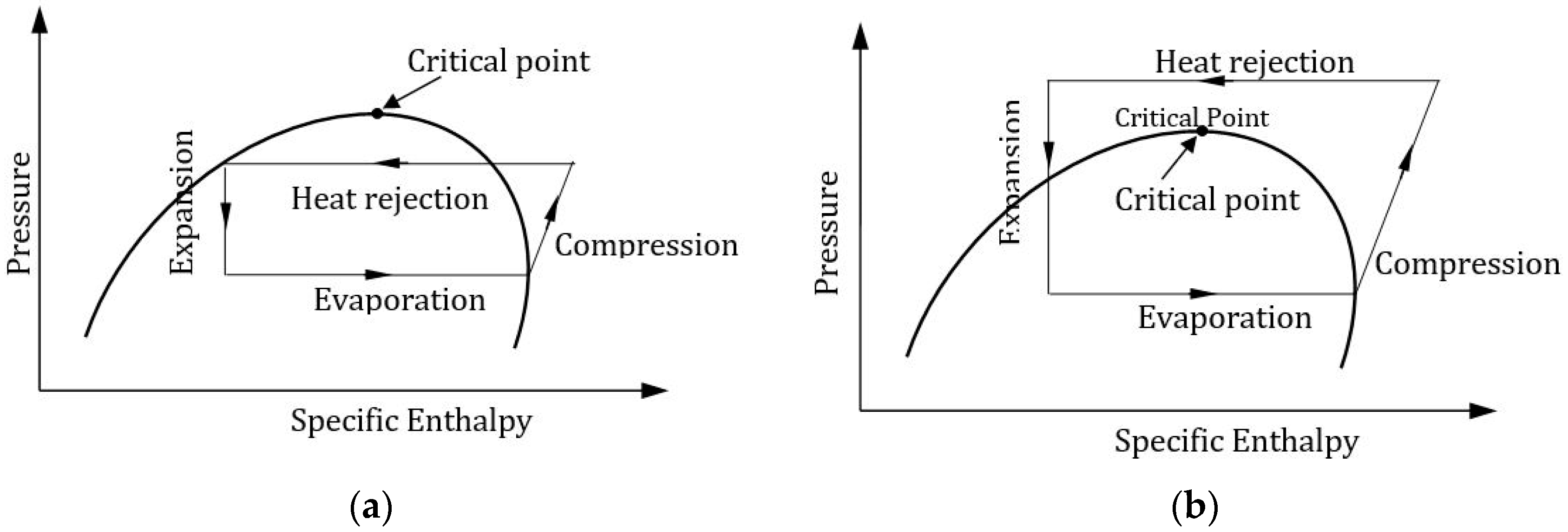
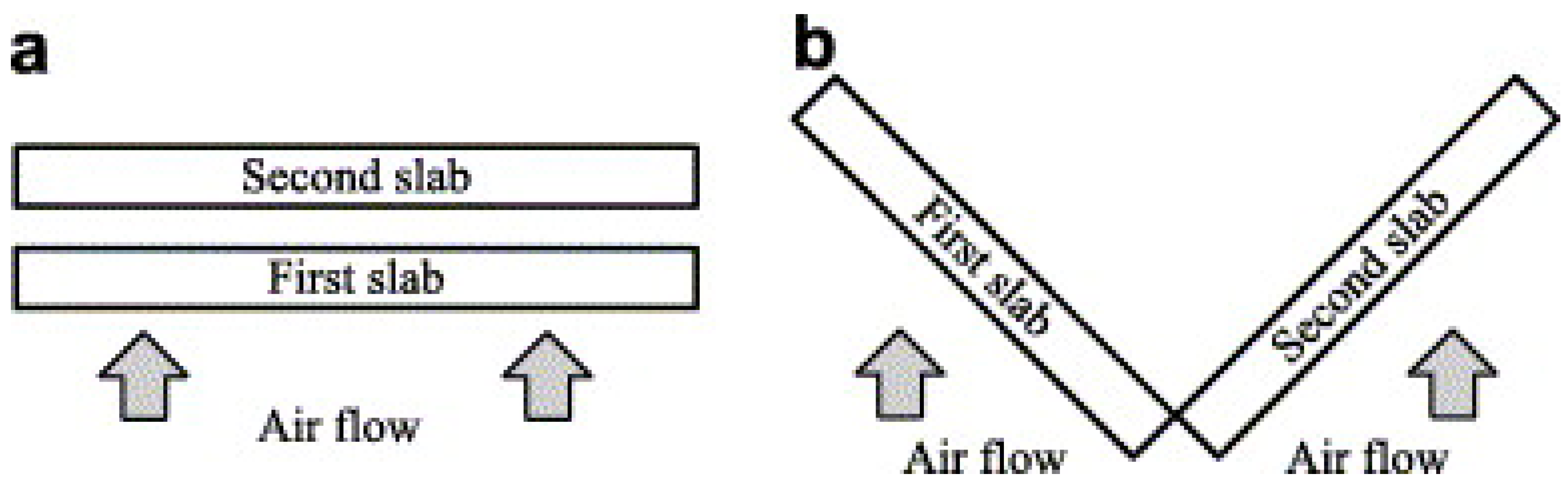
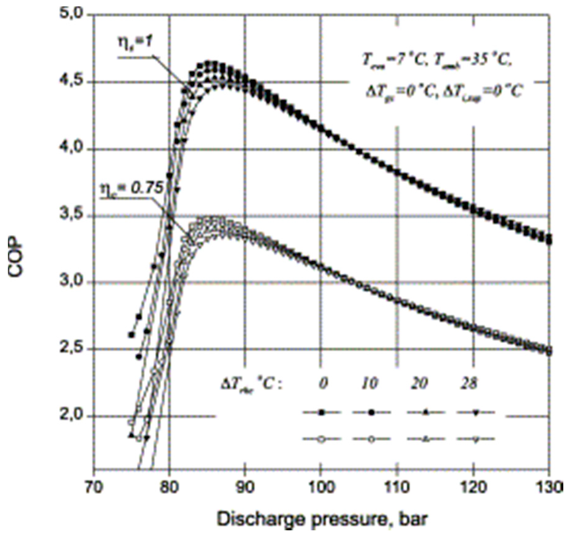
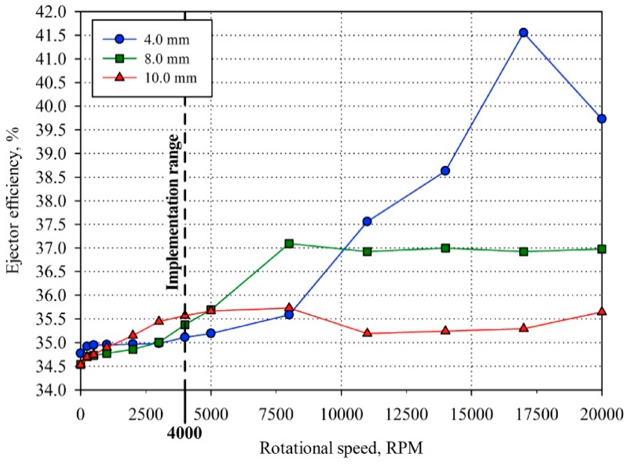
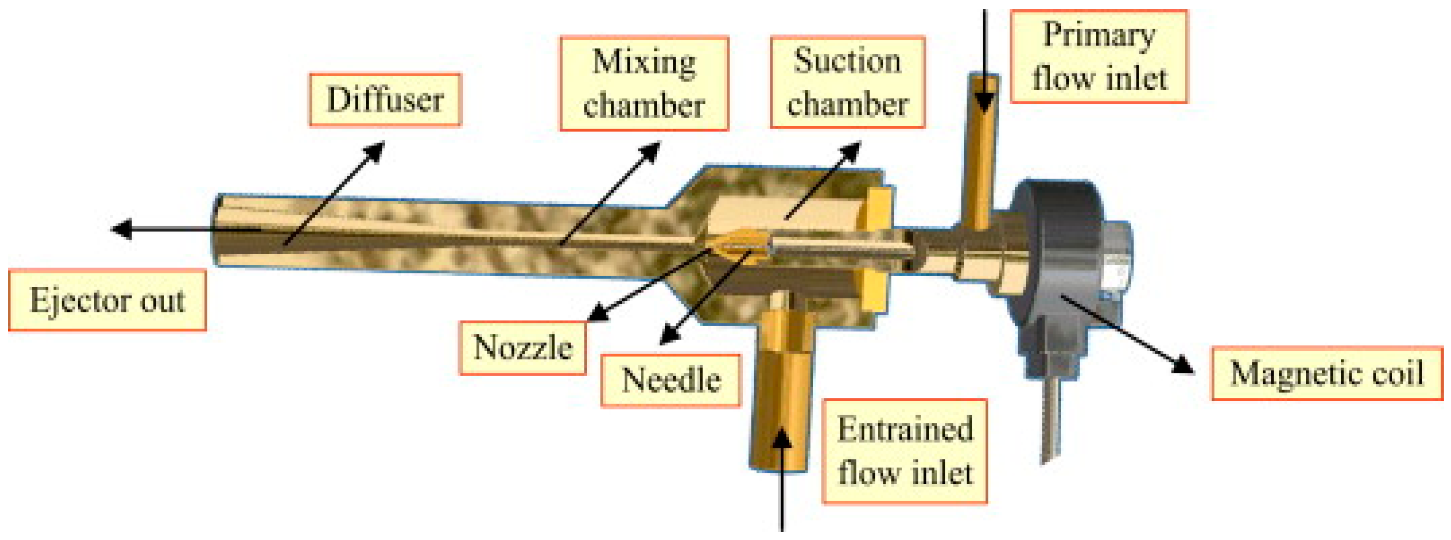
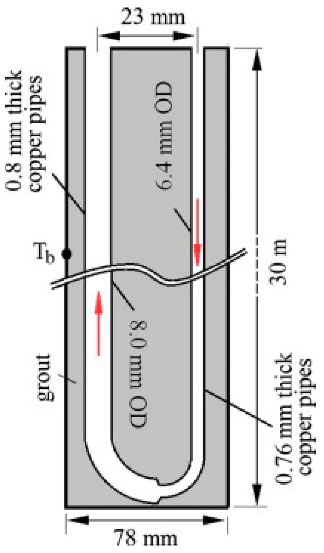
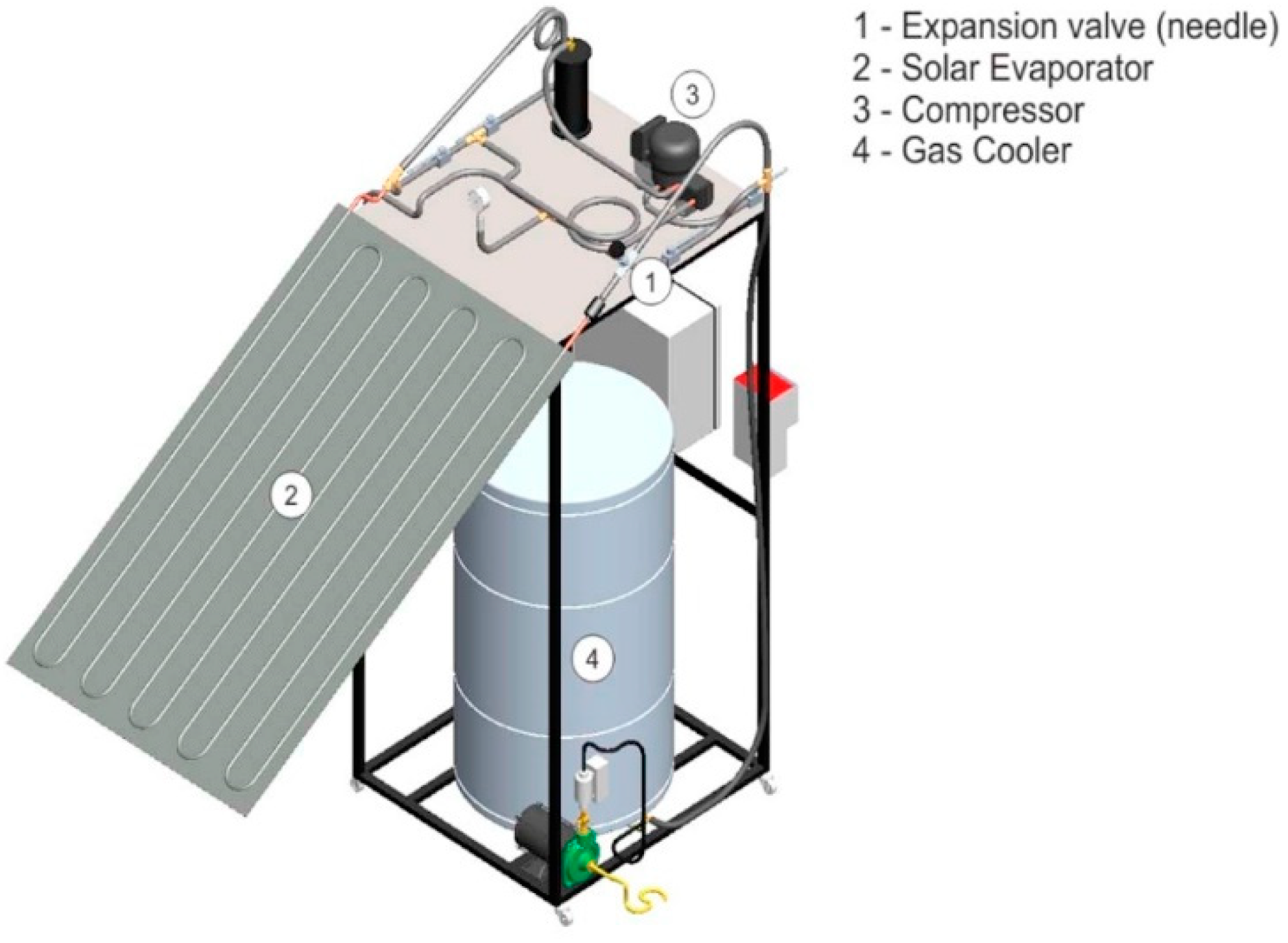
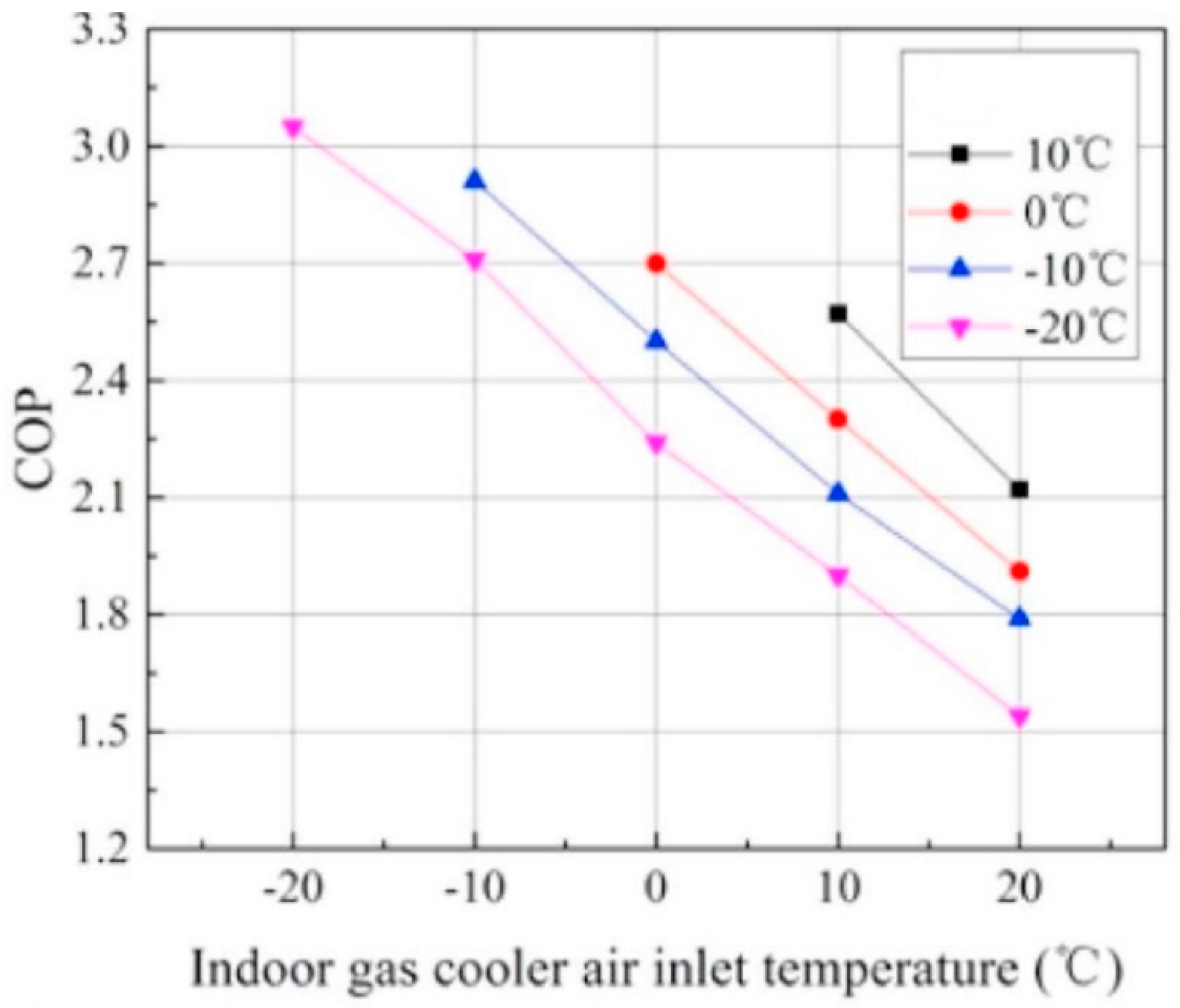
Table 1.
Basic properties of CO2 (R744) compared with other refrigerants [6].
Table 1.
Basic properties of CO2 (R744) compared with other refrigerants [6].
| Properties | R744 | R22 | R134A | R410A |
|---|---|---|---|---|
| ODP/GWP | 0/1 | 0.05/1700 | 0/1300 | 0/1900 |
| Flammability/toxicity | N/N | N/N | N/N | N/N |
| Molecular mass (kg/kmol) | 44.0 | 86.5 | 102.0 | 72.6 |
| Critical pressure (MPa) | 7.38 | 4.97 | 4.07 | 4.79 |
| Critical temperature (°C) | 31.1 | 96.0 | 101.1 | 70.2 |
| Refrigeration capacity (kJ/m3) | 22545 | 4356 | 2868 | 6763 |
Table 2.
Recent significant studies on CO2 heat pump system components.
| Heat Pump Components | References | Type of Study | Unique System Features | Nature of Study | Major Findings | ||
|---|---|---|---|---|---|---|---|
| Theoretical | Experimental | Energy | Exergy | ||||
| Gas Cooler | Yin et al. [11] |
|
| ||||
| Xie et al. [14] |
|
| |||||
| Chen [15] |
|
| |||||
| Yang et al. [18] |
|
| |||||
| Qi et al. [19] |
|
| |||||
| Yu et al. [20] |
|
| |||||
| Evaporator | Yamaguchi et al. [21] |
|
| ||||
| Yun et al. [22] |
|
| |||||
| Elbel et al. [23] |
|
| |||||
| Brown et al. [24] |
|
| |||||
| Compressor | Jiang et al. [25] |
|
| ||||
| Rozhentsv and Wang [26] |
|
| |||||
| Hiwata et al. [27] |
|
| |||||
| White et al. [28] |
|
| |||||
| Expansion Device | Yang et al. [13] |
|
| ||||
| Xing et al. [29] |
|
| |||||
| Boccardi et al. [30] |
|
| |||||
| Agrawal et al. [31] |
|
| |||||
| Internal Heat Exchanger | Yamaguchi et al. [21] |
|
| ||||
| Kim et al. [32] |
|
| |||||
| Xing et al. [29] |
|
| |||||
| Tao et al. [33] |
|
| |||||
Table 3.
A summary of studies conducted on CO2 heat pump systems.
| Categorization | References | Type of Study | Salient Design Features | Applications | Major Findings | |
|---|---|---|---|---|---|---|
| Theoretical | Experimental | |||||
| Water Source Heat Pump | Mayekawa [116] |
|
|
| ||
| Liu et al. [117] |
|
|
| |||
| Air Source Heat Pump | Hu et al. [118] |
|
|
| ||
| Calabrese et al. [119] |
|
|
| |||
| Hu et al. [120] |
|
|
| |||
| Ground Source Heat Pump | Kim et al. [32] |
|
|
| ||
| Wang et al. [121] |
|
|
| |||
| Hybrid Solar | Faria et al. [122] |
|
|
| ||
| Li et al. [123] |
|
|
| |||
| Cho et al. [124] |
|
|
| |||
| Chaichana et al. [125] |
|
|
| |||
| Hybrid Geothermal | Jin et al. [126] |
|
|
| ||
| Jin et al. [127] |
|
|
| |||
| Kim et al. [128] |
|
|
| |||
© 2019 by the authors. Licensee MDPI, Basel, Switzerland. This article is an open access article distributed under the terms and conditions of the Creative Commons Attribution (CC BY) license (http://creativecommons.org/licenses/by/4.0/).
Share and Cite
MDPI and ACS Style
Rony, R.U.; Yang, H.; Krishnan, S.; Song, J. Recent Advances in Transcritical CO2 (R744) Heat Pump System: A Review. Energies 2019, 12, 457. https://0-doi-org.brum.beds.ac.uk/10.3390/en12030457
AMA Style
Rony RU, Yang H, Krishnan S, Song J. Recent Advances in Transcritical CO2 (R744) Heat Pump System: A Review. Energies. 2019; 12(3):457. https://0-doi-org.brum.beds.ac.uk/10.3390/en12030457
Chicago/Turabian StyleRony, Rajib Uddin, Huojun Yang, Sumathy Krishnan, and Jongchul Song. 2019. "Recent Advances in Transcritical CO2 (R744) Heat Pump System: A Review" Energies 12, no. 3: 457. https://0-doi-org.brum.beds.ac.uk/10.3390/en12030457
Note that from the first issue of 2016, this journal uses article numbers instead of page numbers. See further details here.