Review

DC-DC Converter Topologies for Electric Vehicles, Plug-in Hybrid Electric Vehicles and Fast Charging Stations: State of the Art and Future Trends

1
ETEC Department & MOBI Research Group, Vrije Universiteit Brussel (VUB), Pleinlaan 2, 1050 Brussels, Belgium
2
Flanders Make, 3001 Heverlee, Belgium
*
Author to whom correspondence should be addressed.
Submission received: 28 February 2019 / Revised: 4 April 2019 / Accepted: 16 April 2019 / Published: 25 April 2019

Abstract

:
This article reviews the design and evaluation of different DC-DC converter topologies for Battery Electric Vehicles (BEVs) and Plug-in Hybrid Electric Vehicles (PHEVs). The design and evaluation of these converter topologies are presented, analyzed and compared in terms of output power, component count, switching frequency, electromagnetic interference (EMI), losses, effectiveness, reliability and cost. This paper also evaluates the architecture, merits and demerits of converter topologies (AC-DC and DC-DC) for Fast Charging Stations (FCHARs). On the basis of this analysis, it has found that the Multidevice Interleaved DC-DC Bidirectional Converter (MDIBC) is the most suitable topology for high-power BEVs and PHEVs (> 10kW), thanks to its low input current ripples, low output voltage ripples, low electromagnetic interference, bidirectionality, high efficiency and high reliability. In contrast, for low-power electric vehicles (<10 kW), it is tough to recommend a single candidate that is the best in all possible aspects. However, the Sinusoidal Amplitude Converter, the Z-Source DC-DC converter and the boost DC-DC converter with resonant circuit are more suitable for low-power BEVs and PHEVs because of their soft switching, noise-free operation, low switching loss and high efficiency. Finally, this paper explores the opportunity of using wide band gap semiconductors (WBGSs) in DC-DC converters for BEVs, PHEVs and converters for FCHARs. Specifically, the future roadmap of research for WBGSs, modeling of emerging topologies and design techniques of the control system for BEV and PHEV powertrains are also presented in detail, which will certainly help researchers and solution engineers of automotive industries to select the suitable converter topology to achieve the growth of projected power density.

1. Introduction

Vehicles have been shaping human civilization for centuries and expanding their horizons beyond a few localized communities and automobiles are the most modern form of this vehicle transportation. The increasing usage of conventional automobiles is causing harm to the environment and human life, as these automobiles burn petrol, diesel or natural gas and produce carbon dioxide (CO2), sulfur dioxide (SO2) and oxides of nitrogen as harmful exhaust components. In the EU, the transportation sector is accountable for approximately a quarter of greenhouse gas (GHG) emissions as illustrated in Figure 1 [1]. While GHG emissions from other sources were decreasing by 15% from 1990 to 2010, GHG emissions in the transportation sector increased up to 36% in the same period [2], [3]. To combat this situation and to maintain regulation of the signed “Doha Amendment to the Kyoto protocol (2012)”, the replacement of conventional vehicles are gaining the most priority and for this reason, Electric Vehicles (EVs) have been proposed as a better alternative [1,2,3,4,5,6].
Cutting-edge research on EVs tends towards zero carbon electric vehicles, which is one of the major pillars of “3Z” concept: (a) Zero poverty; (b) Zero unemployment; and (c) Zero net-carbon emissions [7]. In general, the EVs are divided into three basic categories: Battery Electric Vehicles (BEVs), Plug-in Hybrid Electric Vehicles (PHEVs) and Fuel Cell Electric Vehicles (FCEVs); Table 1 presents the fundamental comparison between these three categories of EVs.
The mass consumption of EVs, which rely on low GHG emission, has excellent potential to significantly reduce the use of GHG-emitting transportation fuels [15,16,17,18]. Therefore, the vehicle industries have had little option but to shift towards EV powertrains. Moreover, as shown in Figure 2, EV trading is forecast to increase by a further 75% within the next two years. According to the 2017 International Energy Agency (IEA) report, research needs to be conducted focusing on the BEV and PHEV powertrains to meet the demand slope in coming years [19], whereas FCEVs are an underdeveloped area to date due to the high cost of fuel cells, production, transportation and storage of hydrogen, and the life cycle and reliability of the fuel cells [10,11].
In the BEV and PHEV powertrains, electric sources (i.e., battery and/or supercapacitors) are connected to the inverter through a high voltage (HV) DC bus to drive an HV three-phase electric motor (EM) as shown in Figure 3 [20,21,22,23], which depicts a representative architecture of an EV powertrain with charging systems.
The electric sources of BEV and PHEV powertrains are unregulated and have some specific problems, notably batteries and supercapacitors (SCs) face voltage drops during operation, and in case of the fuel cells (FCs), the dynamic response during the transient process is relatively slow and causes a high voltage drop in a short span of time after transition [18,24,25,26,27,28,29,30,31]. Furthermore, FCs encounter many problems compared to batteries and SCs due to the limited supporting infrastructure such as very few refueling stations, and high initial cost due to limited production and reliability of the fuel cells [14,32]. Therefore, the scope of utilizing FCs in EVs is limited and also out of the scope of this paper [18,26,33]. Moreover, SCs are suitable for capturing electricity during regenerative braking and delivering power instantaneously for acceleration due to their fast charging and discharging potential. In contrast, a battery is appropriate for providing long-term energy with a relatively high energy density, mature reliability and compact size. Merging batteries with SCs as a hybrid energy storage system reduces stress over the batteries and ensures a fast dynamic response as well as a long lifespan while increasing the cost of the system [34]. A comparative analysis of electric sources is outlined in Table 2.
As shown in Figure 3, each energy source might require a specific DC-DC converter to be integrated into the high voltage (HV) DC link of the powertrain. For bidirectional electric sources like SCs and batteries, bidirectional DC-DC converters are essential to absorb the regenerative braking energy, which maximizes the overall efficiency of the system. However, these bidirectional sources also have different requirements for the connected DC-DC converters. For example, due to the fast charging and discharging capability of SCs, a fast-dynamic controlled converter is required to avoid incompatible operations [41,42]. A DC-DC converter with a small number of passive components is preferable when the energy source is an SC, to lessen transition intervals between the charging mode and the discharging mode, which is generally around a few microseconds [34,38,41]. In the case of batteries, fast dynamic control is not necessary because a charging profile roughly lasts from 30 min to a few hours [18,32], although it is essential to reduce the ripples from the input current to prolong the lifespan of the batteries [39,43]. Despite having different characteristics, there are some common characteristics in the DC-DC converter topologies. These characteristics are a DC-DC converter with high voltage gain and having the capability of delivering power over a wide range of voltage. Moreover, the output voltage of batteries and SCs are unregulated and low; therefore, an HV DC-DC converter is required to increase the low unregulated electric source voltage to a highly regulated level by transitorily storing the source energy. This energy is stored either in electric field storage elements (capacitors) or in magnetic field storage elements (single inductor/multiport inductor/coupled inductor/interleaved inductor) using active switching components (IGBTs/ MOSFETs) and diodes [21,44,45,46,47,48,49,50,51].
An argument could be made for using a transformer to step-up the output AC voltage level instead of using a DC-DC converter. However, the advantages of using the DC-DC converter is that it is lightweight, compact in size, low-priced, highly efficient and reliable [52]. Moreover, an HV battery can be used instead of an HV DC-DC converter with a complex battery management system (BMS). Hence, an HV DC-DC converter will reduce the number of series of battery cells and the complexity of the BMS. Achieving a high DC link voltage is required to enhance the inverter performances. Moreover, an HV DC-DC converter can afford higher DC link voltage than HV battery, which also increases the efficiency of the power electronics components and the EM [45]. According to the requirements of a dedicated drivetrain, the output of the DC-DC converter can be regulated spontaneously during a rush driving period, which adds another degree of freedom (DoF) in the system. Despite all the benefits listed, an HV DC-DC converter has several drawbacks: very flat voltage gain with moderate gate pulse switching, inefficiency to attain high power density, low efficiency due to hard-switching technique, hard to design robust high bandwidth control loop due to presence of Right Half Plane Zero (RHPZ) in the transfer function and losses generating from the HV DC-DC converter unit itself [21,44,51]. To overcome these impediments of conventional DC-DC converters, researchers are exploring emerging WBGSs (i.e., silicon carbide, gallium nitride), modeling new converter topologies and designing novel control concepts for high-voltage gain and high-power application to ensure high power density and high efficiency while attaining desire reliability. Different viable topologies of the DC-DC converter can be opted for BEV and PHEV powertrains. However, a small-sized, reliable, parameterized, lightweight, controllable, scalable, and efficient DC-DC converter has a higher demand in automotive industries. Some of these characteristics can be attained by using the interleaving technique of boost converter [49,53,54,55,56]. Full-bridge boost converters can also be selected for BEVs and PHEVs if galvanic isolation is required between the source and the load [57,58,59]. To overcome the hard switching characteristics of the DC-DC converter, Zero-Voltage Switching (ZVS) and Zero-Current Switching (ZCS) source converters are employed in BEVs and PHEVs [60,61,62,63,64]. This paper illustrates multiphase, multiport or multidevice boost converter topologies which connect multiple electric sources using the parallel connection of switching converters with interleaved control technique. Isolated and non-isolated multi-phase interleaved converters are selected for vehicular applications due to their capability of improving the performance of the electric sources and demand for low ripples with tight tolerance. These converter topologies can minimize input current ripples and output voltage ripples without increasing the passive components’ size (inductor and capacitor size), attain high bandwidth control, improve the overall efficiency, integrated thermal distribution, and reliability of the system [65,66,67,68,69,70,71,72,73,74]. However, these topologies have sensitivity and stability problems due to the duty cycle at load changes, and scalability problems as multiple numbers of components are used. Each topology has its own benefits and drawbacks and should be selected based on the requirements, overall cost, device size, efficiency, and reliability.
Nowadays, charging time and the number of available charging stations are the most significant concerns for BEV and PHEV customers. These two factors have a vital influence on the purchase rate of EVs according to a survey conducted of over 5000 customers by Nissan Motor Co. as shown in Figure 4 [75,76,77].
To achieve widespread penetration of EVs in the future, building highly efficient FCHARs and deploying many FCHARs are mandatory tasks. Generally, charging stations can be categorized into three types. Type I uses standard 120 VAC (US) and 230 VAC (EU) and is recommended for residential charging. Type II is specified for a public solution and uses 240 VAC (US) and 400 VAC (EU), whereas Type III is used for commercial and municipal applications like petrol refueling stations and it is served by a 480 VDC and are also known as FCHARs. The utilization of a high-power converter with fast charging compatibility is a promising solution to reduce the charging duration. Recently developed, an FCHAR can recharge up to 80% of a standard 25 kWh BEV within 30 min [78]. Currently, the converter topologies for FCHAR are in the development stage where the prime issue is minimizing the price of FCHAR power modules and infrastructures. Existing price of a dual-plug 50 kWh fast charging system is $35,000/unit, whereas the expense is only $5,000/unit for a Type II charger [79,80]. Therefore, research conducted on fast charging converters should aim to reduce the component count, component cost and overloading of transformers while confirming better reliability [81,82,83]. FCHARs’ electric infrastructure is typically categorized into two designs, the first one is a common AC bus architecture and the other one is a common DC bus architecture. Converter topologies for both architectures are reviewed in detail in term of component count, control, isolation and efficiency. Moreover, standard guidelines and codes need to be developed to define the baseline for FCHARs to ensure their safe and sustainable energy utilization in a city [84]. Finally, for FCHARs a compact size, lower cost and highly efficient converter with high power density and high reliability are essential.
Presently, the DC-DC converters utilized in BEV and PHEV powertrains primarily use Si-based semiconductors which limits their efficiency to 92–93%, allows a maximum switching frequency up to 30 kHz and attains only 3–12 W/in3 power density [78,85,86,87,88]. However, the performance of Si-based semiconductors is limited due to their physical properties and characteristics and further development of Si-based semiconductors is not thought possible [89,90,91]. On the other hand, use of WBGSs have brought about drastic improvements in the power density (~50 W/in3) as well as efficiency while ensuring better manufacturability at minimal cost. Contemporary research into WBGSs [85,90,92,93,94,95] have found that silicon carbide (SiC) semiconductors are highly suitable for designing high powered DC-DC converters due to its capability for handling vast power ranges up to 100 kW, lower cost, better packaging, high thermal conductivity, and availability on the market. On the other hand, gallium nitride (GaN) semiconductors are at a mature level for commercial use with breakdown voltages (BDVs) of less than 600 V and power ratings of less than of 5 kW [88,96]. However, more research needs to be conducted on GaN-based semiconductors to advance adaptation in the converters of BEVs, PHEVs and FCHARs. Qualification, packaging and reliability are significant challenges that are holding back GaN-based device production for high power applications. However, recently a high power density and high-efficiency enhancement-mode GaN high-electron-mobility transistor-based onboard charger has been implemented for 7.2 kW rated power having 40 W/in3 power density [97], which indicates high prospects for GaN in automotive industries in the near future. Furthermore, the automotive industries are looking forward to a mature WBGSs technology 2~3 times cheaper than Si devices, particularly after 2020 as EVs will have an approximately 21% compound annual growth rate by this time [98].
This paper presents a comprehensive review of different DC-DC converter topologies used in BEVs and PHEVs: Boost DC-DC converter (BC), Interleaved 4-Phase Boost DC-DC converter (IBC), Boost DC-DC Converter with Resonant circuit (BCRC), Full bridge Boost DC-DC converter (FBC), Isolated ZVS DC-DC converters (ZVSC), Sinusoidal Amplitude HV DC bus converter (SAHVC), Multiport isolated DC-DC converter (MPC), and Multi-device Interleaved Bidirectional DC-DC converter (MDIBC). This paper investigates best possible DC-DC converter entrants for interfacing between the electric sources and the motor drive circuit. Moreover, the paper also studies different converter topologies for FCHARs, for both AC-DC stage and DC-DC stage, including 3-level 3-phase Neutral Point Clamped converter, 3-phase Bridgeless Boost converter, 3-phase Vienna rectifier, Multiple Interleaved Buck converters, Full-Bridge LLC resonant converter and Phase-shifted Full-Bridge converter. The advantages and disadvantages of each converter topology regarding power capacity, control aspects and components count are presented in detail.
This review paper is structured into nine different sections. After this brief introduction, Section 2 presents a classification of DC-DC converter topologies used in vehicular applications. In Section 3, an overview of DC-DC converter topologies for BEVs and PHEVs is portrayed. In Section 4, design parameters are identified based on the requirement of BEV and PHEV powertrains. Section 5 demonstrates an overview of converter topologies for FCHARs. Section 6 investigates the performance of DC-DC converters using Si and WBGSs. Section 7 provides a broad comparison between different DC-DC converter topologies for both EVs and FCHARs. In Section 8, future trends of research are presented in detail. Finally, Section 9 concludes commenting over suitable DC-DC converter topologies for BEV and PHEV powertrains and converter topology for FCHARs.

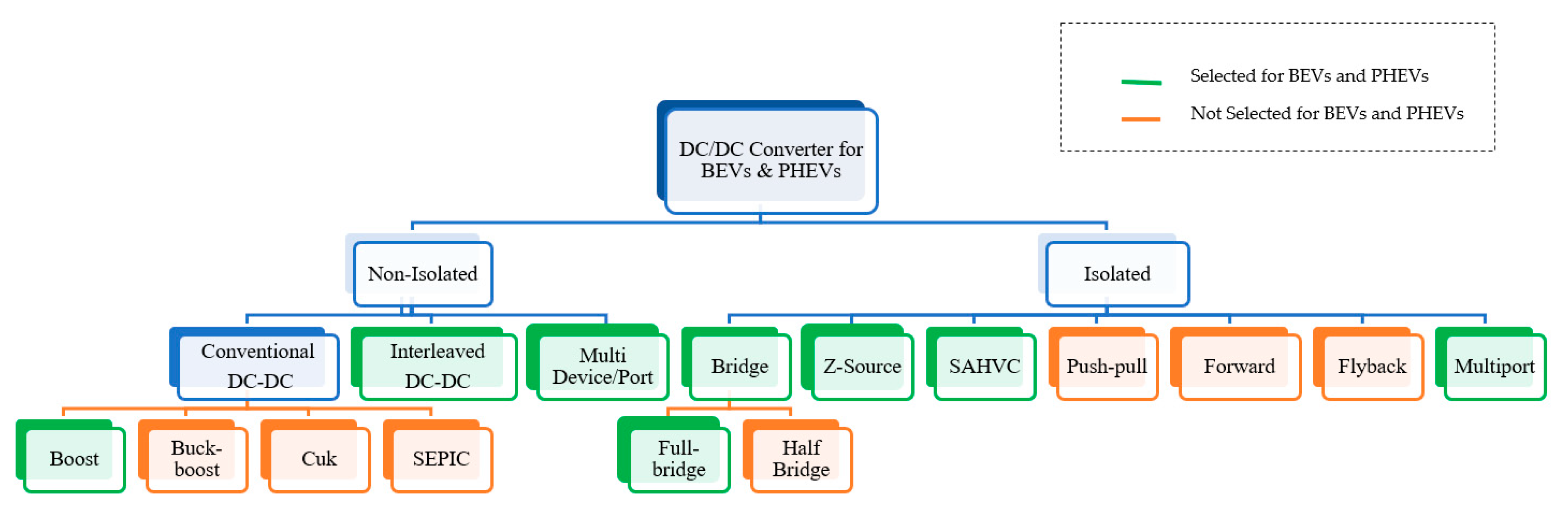
2. Categories of DC-DC Converter for EVs’ Powertrain

Figure 5 depicts a general classification of DC-DC converter topologies for BEV and PHEV powertrains. In this section, extensive details about each topology with their characteristic functions is discussed.

2.1. Non-Isolated DC-DC Converters for BEVs and PHEVs

Non-isolated DC-DC converters are frequently used in medium and high-power vehicular applications [99,100,101]. Among them, conventional boost DC-DC converters and interleaved Boost DC-DC converters are commonly used for BEV and PHEV powertrains due to their simple architecture, cost-effectiveness and accessible control strategy. These two converters are used at low and medium DC link voltage applications. For example, in [51], a boost DC-DC converter is employed where low DC voltage gain is required (<4%). For a low level of DC voltage gain, there are four types of converter available: boost converter [49], buck-boost converter [44], Ćuk converter [102] and SEPIC converter [103]. Among all these the boost converter topology is selected for BEVs and PHEVs because only a positive voltage gain (>1) is required for motor action; whereas buck-boost converters, Ćuk converters, and SEPIC converters can be used for both voltage step-up and step-down operation. Moreover, Ćuk and SEPIC are current-voltage-current converters, which are only suitable for energy storage systems (ESSs), whereas the inputs can be a battery and/or a SC in vehicular applications [102,103,104]. The high inrush output current and use of a large volume filter capacitor make the buck-boost topology inconvenient in automotive applications [105].
Again, when a high gain DC Bus voltage is required (>4%), the interleaved 4-Phase interleaved boost converter is employed. Interleaved Boost Converters (IBCs) can step up the voltage more than a 4:1 ratio with minimum input current ripples and output voltage ripples, and this makes IBCs a more lucrative non-isolated converter topology [35,36,37,38]. Moreover, a non-isolated Multidevice/port Interleaved Bidirectional Converter (MDIBC) has been proposed for high power automotive applications [54]. All other non-isolated DC-DC converters transfer energy between two ports, an input port and an output port, while multidevice converters can transfer energy from two or three different input ports to a single output port as multi-input single output (MISO) system [70,71,72].

2.2. Isolated DC-DC Converters for BEVs and PHEVs

Isolated DC-DC converters are often used in low and medium-power vehicular applications [106,107]. Among them, the full-bridge isolated DC-DC converter is the most popular topology for BEV and PHEV powertrains [57,58,59]. Five different types of isolated DC-DC converter topologies are frequently used: half-bridge converter [60], full-bridge converter [57], push-pull converter [108], forward converter [109] and flyback converter [110]. Isolated DC-DC converter operation has three primary stages DC/AC/DC. The intermediate AC stage surges up the input voltage to a higher level using a high-frequency transformer (HFT). The HFT provides galvanic isolation and high voltage gain which are significant issues in BEVs and PHEVs. Full-bridge is the most suitable converter topology among these five types because it reduces voltage and current stresses over switches and diodes which is absent in all other isolated topologies. Moreover, full-bridge design architecture is simple and it improves overall system efficiency with minimal cost [44,49,50,57].
Z-source converters as single boosting stage (DC/AC) become popular in BEV and PHEV powertrains due to their smooth starting operation, low voltage stress on switching gates and low current ripples [59,60,61,62,63], but they have a limited boosting capability due to the limited voltage gain during the zero vectors. Moreover, a Sinusoidal Amplitude High Voltage bus converter (SAHVC) suppresses the EMI from the circuity which results in low dv/dt and di/dt rates in switch on mode and switch off mode [60]. Due to this feature, the SAHVC can function properly at high switching frequencies with minimal switching losses while maintaining a high-power density. Moreover, isolated-MPC is the best-suited candidate in BEVs and PHEVs because it reduces input current ripples and output voltage ripples, minimizes the size of passive components, improves efficiency and having high power handling capability [47,48,49,50,51,52,53].

3. Overview of DC-DC Converter Topologies

This section presents the advantages and disadvantages of different competitive DC-DC converter topologies suitable for BEV and PHEV powertrains, which are highlighted in green in Figure 5. The converters are switched using power transistors and are categorized based on working principle, operation mode, power level and power flow direction. Generally, in the automotive sector, the voltage level of the battery storage system is ~250–360 V and the voltage level of SC is ~150–400 V, which are lower than the required voltage of ~400–750 V for the load (EM) [51]. Therefore, step up HV DC-DC converter topologies are used in BEV and PHEV powertrains and the topologies reviewed in this section are step-up converters.

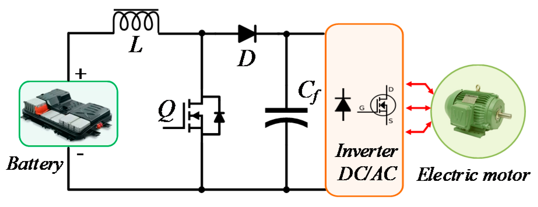
3.1. Boost DC-DC Converter (BC)

The boost DC-DC converter is a power converter that steps-up the input voltage while stepping down the input current. It is a class of switched-mode power supply (SMPS) having at least one energy storage element (a capacitor, an inductor, or the two in combination) and at least two semiconductors (a diode and a switch) as shown in Figure 6 [111,112]. In BC, a series connected inductor with the input DC source helps to reduce input current ripples and a capacitor-based filter is used at the output side to eliminate the output voltage ripples. Boost DC-DC converters have various advantages. A moderate output voltage gain can be obtained (<4%), the switch can be easily driven concerning ground, the input current is continuous and filtering and meeting EMI requirements are simple for this converter [49,51,111]. For the design shown in Figure 6, a moderate efficiency can be achieved (83~85% at full load) [49]. The output voltage is single polarity and circuitry is rather simple, thus the cost is lower, which makes it a suitable option for BEV and PHEV powertrains.
However, the boost DC-DC converter also has some drawbacks. As the requirement of a large capacitor to reduce the ripple at the output voltage, which makes the volume quite large and weight moderately heavy, high voltage gain (>4%) is not suitable for this converter, parallel arrangement of the power-switching devices are required to handle high-power and it requires extra stages to make it short-circuit proof [113].

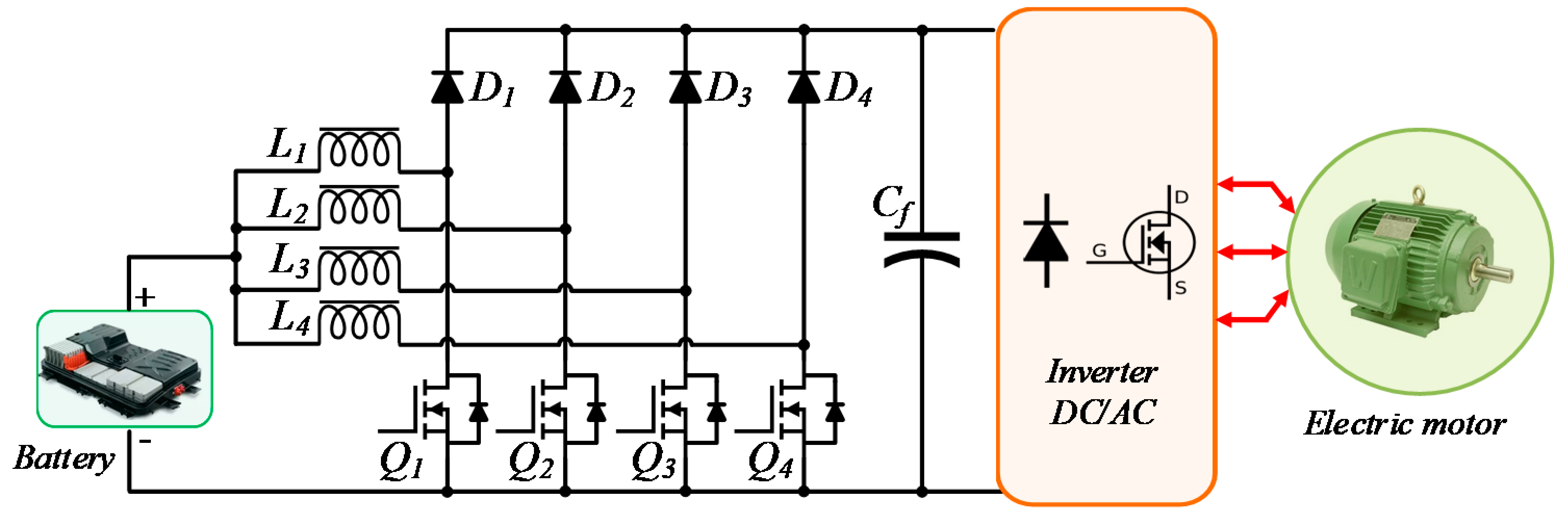
3.2. Interleaved 4-Phase Boost DC-DC Converter (IBC)

The Interleaved 4-Phase boost DC-DC converter (IBC) topology allows minimizing the input current ripples and output voltage ripples; it steps up voltage ratio approximately above four times [49]. In this converter, four identical levels are introduced with four inductances (L1, L2, L3, and L4); all these inductors have a separate magnetic core as shown in Figure 7. Successive phase shifting of the power switching devices is fixed by the ratio of switching period (T) and the number of Phases (N).
Each of the step-up converter levels shares the equal amount of current which is delivered by the electric source, and T/N ratio is present as the period ripple content. Thus, the interleaving technique allows the input inductor size and output capacitor size to be reduced. The frequency of the input current ripples is N times higher than the switching frequency fsw because the control signals are interleaved and have a phase angle of 360°/N [52,53,54,55]. As a result, input current ripple and output voltage ripples lessen which is the best reason to choose this converter topology for BEV and PHEV powertrains.
In [49], IBC has an efficiency of 92% at 30 kW load. Around an 8% drop in the efficiency is caused by alternating from discontinuous current mode (DCM) to continuous current mode (CCM). This converter is sensitive to duty cycle ratio change. Moreover, magnetic core influence due to load change is notable and the component count is also high [44,72].

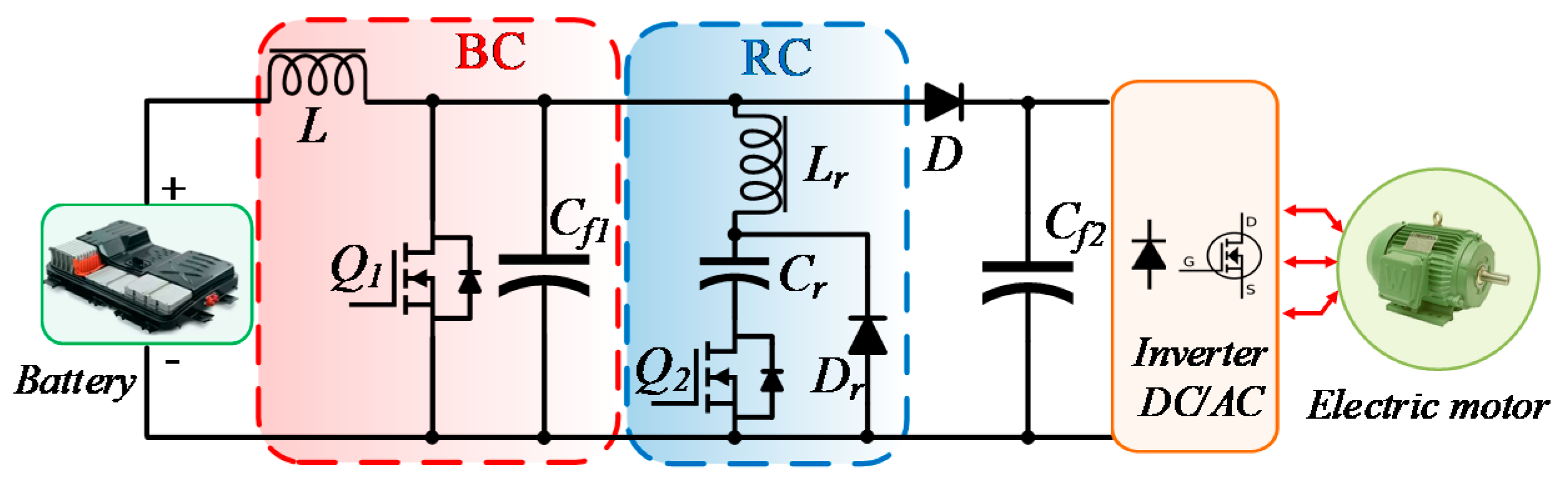
3.3. Boost DC-DC Converter with Resonant Circuit (BCRC)

In BEV and PHEV powertrains, conventional DC-DC boost converters face switching loss problems. To overcome that, soft switching DC-DC converter topologies are utilized. In general, boost converter losses occur due to hard switching, but in soft switching configuration, switching losses are eliminated by forcing voltage (VDS) or current (IDS) to zero during the switching transition. During the turn ON or turn OFF transition time, either voltage VDS is zero, or current IDS becomes zero. As a result, the product of the voltage and current is zero. Thus switching losses can be reduced so that the device can be operated at the high switching frequency, which has a huge impact over the volume and heatsink of the converter.
The soft switching converter configuration consists of two switches, a main Switch Q1 and auxiliary Switch Q2, as shown in Figure 8. The duty cycle of the main switch Q1 is higher than that of auxiliary switch Q2 and determines the average output voltage of the converter. The auxiliary switch Q2, on the other hand, enables the main switch to operate in soft switching mode. Because of the presence of the resonance, the auxiliary switch can work at ZCS mode. Moreover, the ZVS mode is assured by turning on the main switch.
The soft switching characteristics of BCRC assure the reduction of the size and weight of the converter as a large heat sink is not required [44]. Safety regulations are met easily in the converter as the availability of power to load would remain unhampered. During abnormal conditions such as over-voltage or under voltage the converter will still be under protection. However, this converter is only suitable for <5 kW system, substantial output voltage gain is not possible and bidirectionality cannot be achieved [62,113,114].

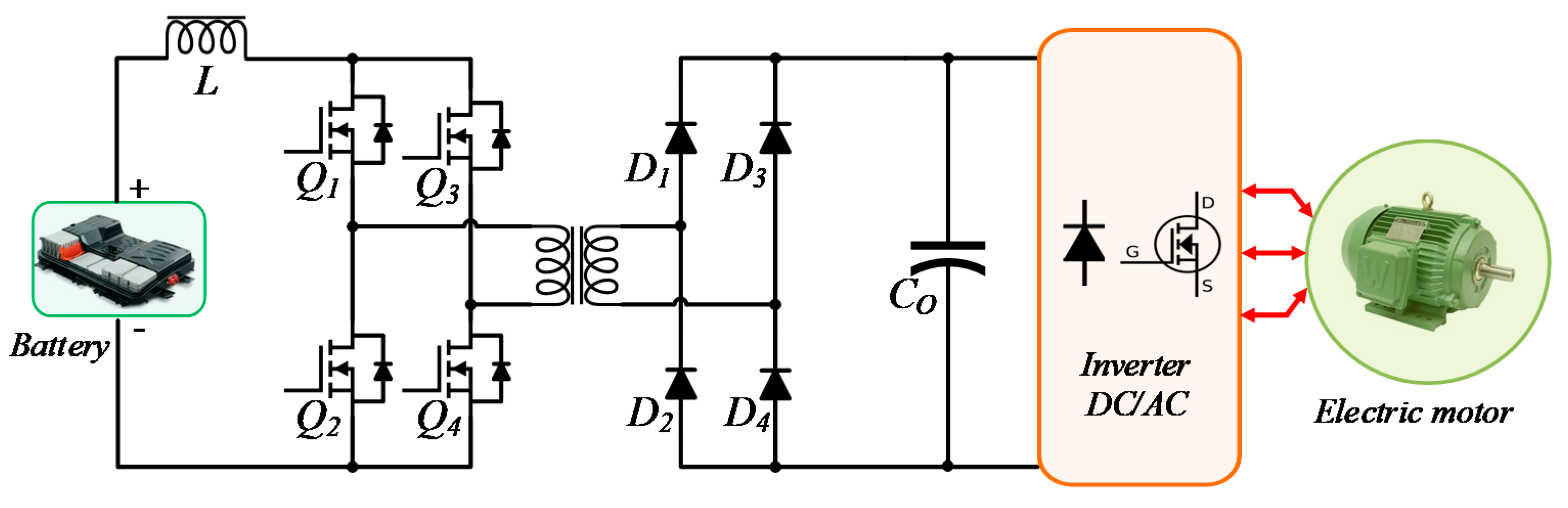
3.4. Full Bridge Boost DC-DC Converter (FBC)

This converter has three functional stages, namely the inverter (conversion from DC to AC), followed by a high-frequency transformer (HFT) (step up the AC voltage), and followed by a rectifier (conversion the AC back to DC). Utilization of the negative portion of the hysteresis loop reduces the core saturation as the current flows in the opposite direction during alternate half cycles, thus making the flux in the core swing from negative to positive. The duty cycle of the PWM signal can be increased or decreased promptly so that the output voltage is held constant even with a varying input source voltage. However, the duty ratio needs to be kept above 50% to protect semiconductor switches. Hence, identical control signals are used in two legs, which alternate with half period duration. As an HFT is used, a high step-up voltage is possible. Moreover, it provides galvanic isolation between the input side and the load side. At 30 kW load, the efficiency of the converter is approximately 91.5% [49]. A current fed FBC is shown in Figure 9.
By using the ZVS technique and phase shifted pulse width modulation (PWM) control, the efficiency can be increased even further. As this is a current fed topology, EMI filter suppression is needed to meet the IEEE regulations standard-519 [115]. Although this converter has moderately high efficiency, the effect of the HFT leakage inductance is crucial because of the high electrical stress in the switching circuit. Thus, a clamping circuit (passive/active) is required to resolve the peak voltage issue in the switching circuit [44,57,58].

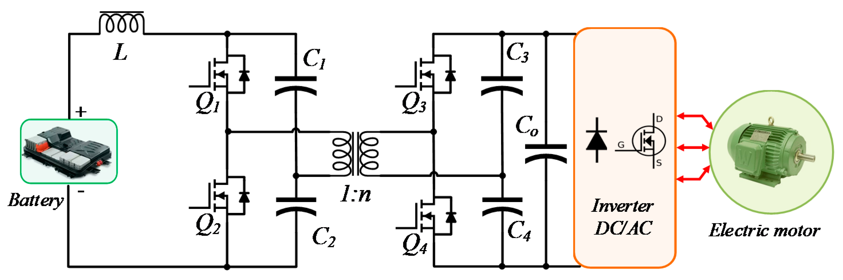
3.5. Isolated ZVS DC-DC Converter (ZVSC)

An Isolated Zero-Voltage Switching (ZVS) DC-DC converter is required for cold starting, soft switching and isolation [61,116]. Compared to the conventional full-bridge step-up DC-DC converters [49], this topology has less circuitry, no total device rating (TDR) consequences, easy control technique, soft switching without additional circuity, and higher efficiency. This isolated ZVS converter is based on a dual half-bridge topology placed on each side of the main transformer as shown in Figure 10. Each switching device has a small parallel capacitor for soft switching. In ZVSC; unified ZVS is attained in either direction of power flow without any additional components [61].
The ZVSC topology can be selected for both the BEV and PHEV powertrains as various components size are reduced. As a result, the power density of the converter is very high. The design has less control and accessory power needs than its full-bridge competitors [61]. All these new features allow efficient power conversion, easy control, lightweight and compact packaging. Hence, ZVSC topology is a suitable replacement for the FBC topology. However, in the high-power applications, there is high voltage stress remaining across the power switches. Hence, the full load current needs to be handled by splitting DC capacitors (C1–C4) across the four switches (Q1–Q4). Moreover, a large filter capacitance (Co) is required for ripple free output voltage. As fault tolerance operation is absent, ZVSCs are not applicable to high power (>10 kW) automotive applications [61,63,117,118,119].

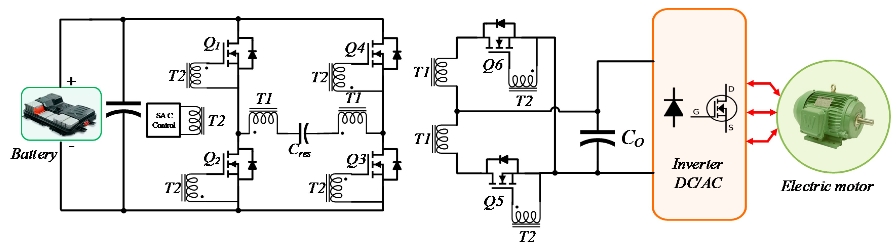
3.6. Sinusoidal Amplitude High Voltage Bus Converter (SAHVC)

The Sinusoidal Amplitude High Voltage bus converter (SAHVC) is one of the fixed ratio voltage converters that performs the HV bus conversion efficiently. This isolated SAHVC combines a full-bridge converter with a half-bridge, and which are placed on each side of the high-frequency multi-windings transformer as shown in Figure 11.
Operation of this converter is based on Symmetrical Continuous Current Conduction mode (SCCC), which reduces voltage stress over the switching circuit [60]. The noise-free operation is ensured in this converter because of common-mode symmetry and high spectral purity. Operating frequency is locked to the powertrain resonant frequency; thus, optimum efficiency is achieved with minimization of the output impedance. Moreover, cancellation of the reactance makes the output impedance lower and resonant tank current is purely sinusoid in form. SAHVC is a noise-free topology, which ensures linear voltage or current conversion with flat output impedance up to 1MHz. Therefore, SAHVC is considered a suitable topology for BEV and PHEV powertrains. However, this converter is not suitable for high power application (>3.5kW) because complex sinusoidal amplitude control (SAC) is required, parameterization is difficult to achieve and due to resonance, a large filter capacitor is needed to compensate the output voltage ripples [60,120,121].

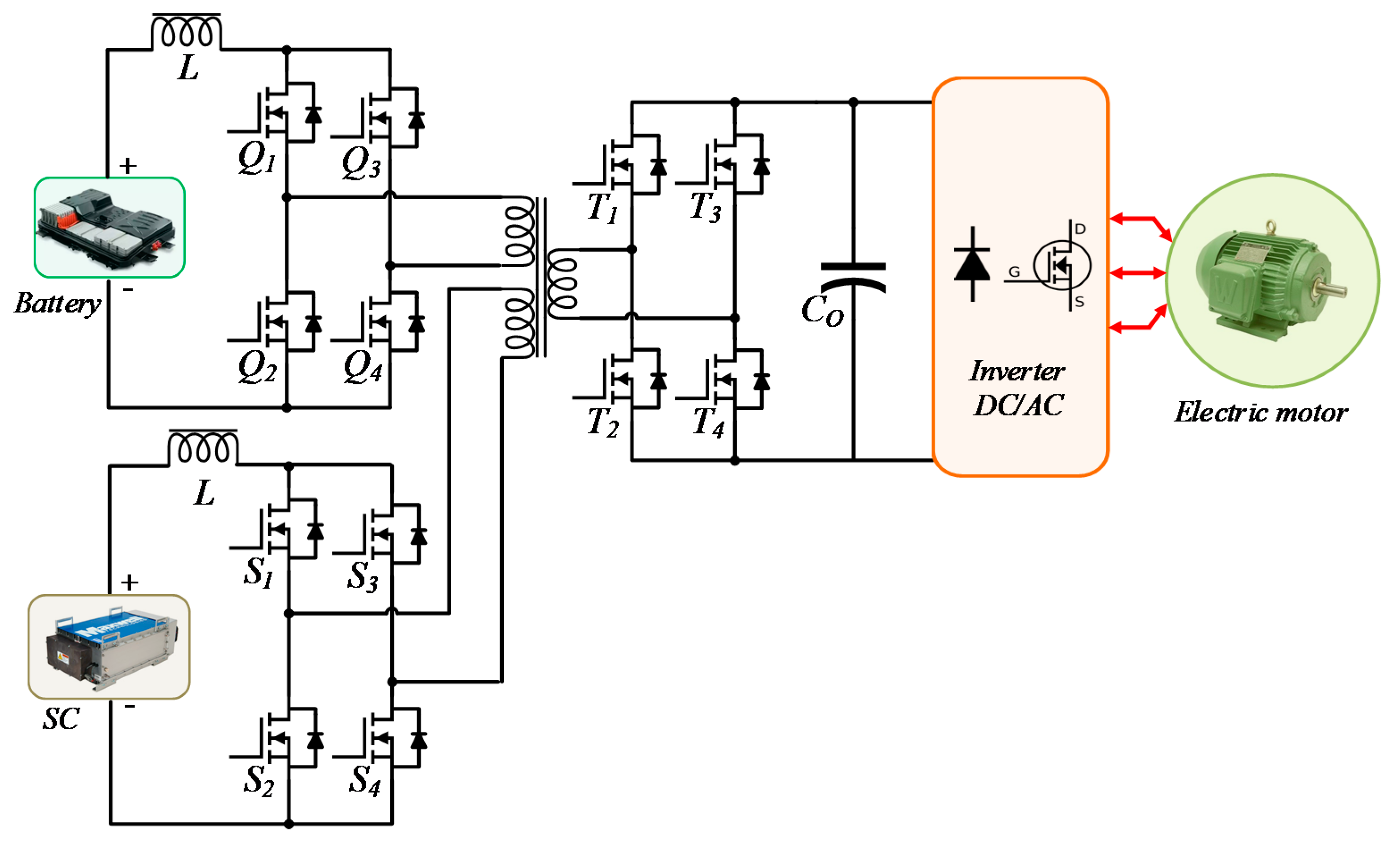
3.7. Multiport isolated DC-DC Converter (MPC)

The Multiport isolated DC-DC converter brings a solution if multiple input sources are required and galvanic isolation is also required between source and load as mentioned in Section 1. In BEVs and PHEVs multiple sources are combined to capture the advantages of an individual source. Furthermore, all the input ports are interconnected by an isolated multi-winding transformer as shown in Figure 12 [51,52]; therefore, all input ports are also entirely isolated from each other. Each input source is connected using an interleaving technique, and this technique can limit the output voltage ripples and input current ripples.
The interleaving control technique of multiport converter highly improves the performance of the DC-DC converter by paralleling and shifting communication of different phases. This controller controls the PWM switching pulses of all switches. In MPC high power density is present. As MPC allows bidirectional power flow, power recovered during regenerative braking can charge the input sources, which improves effectiveness and functionality of the converter. A large switch count in the MPC topology makes synchronization difficult and leads to high component count. Moreover, the presence of the transformer increases the weight of the converter in high power automotive application, the converter is sensitive to duty cycle ratio change at load step and it is difficult to analyze the converter at steady state and transient conditions [69,70,122,123].

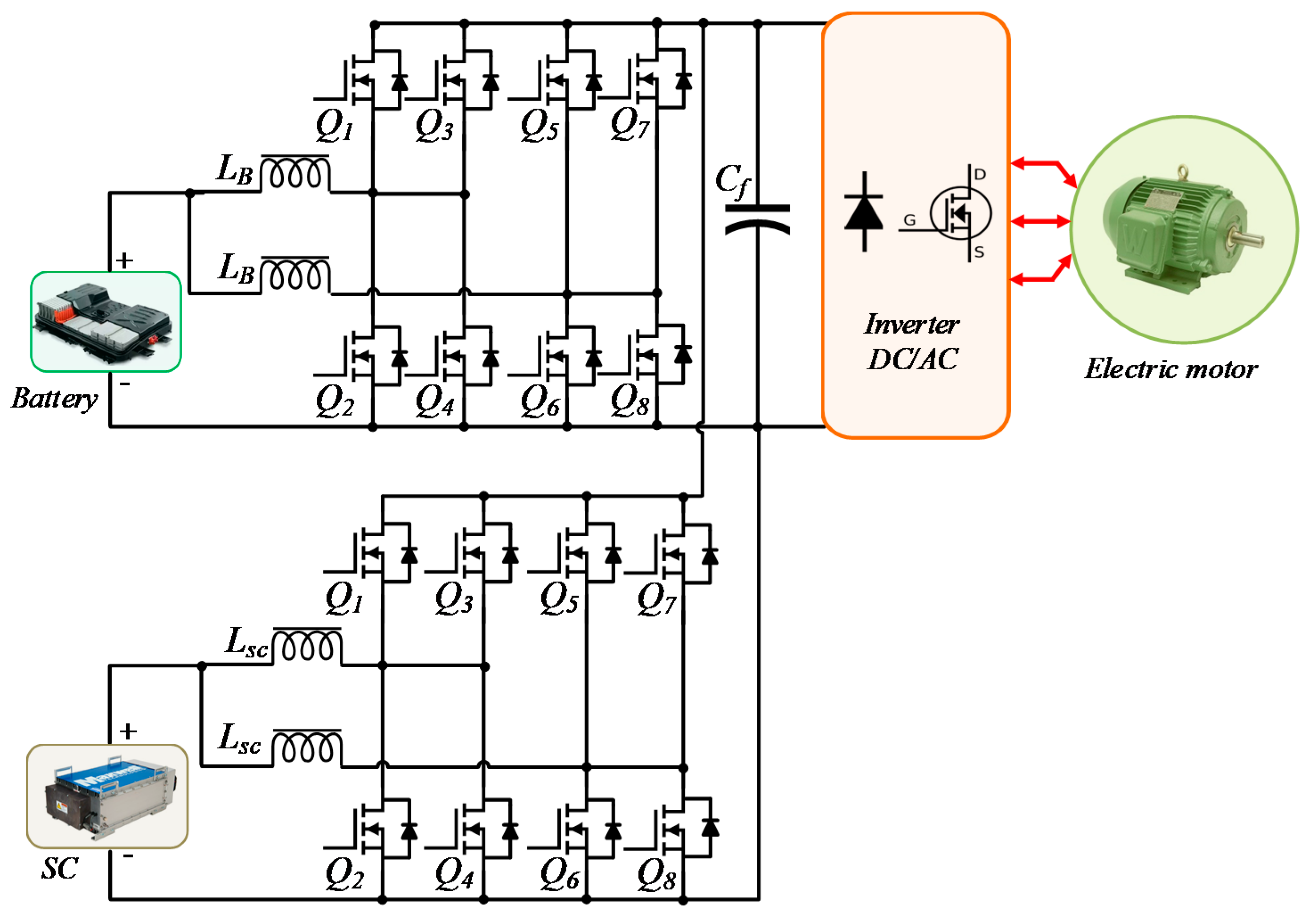
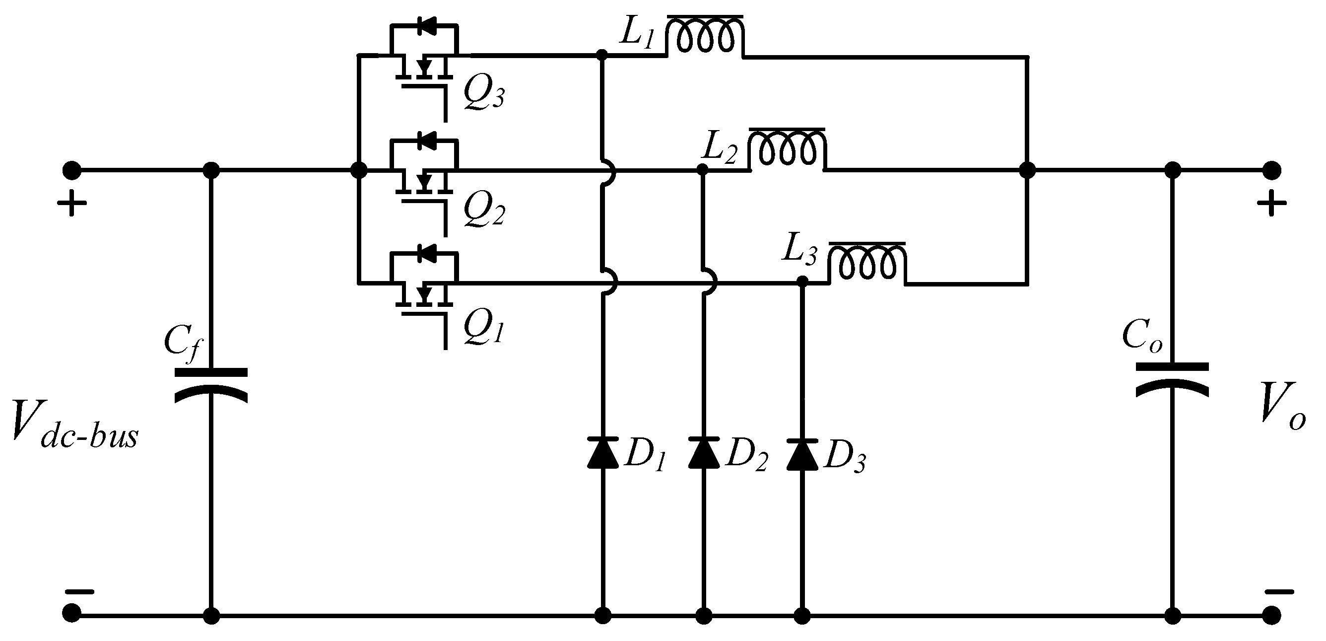
3.8. Multidevice Interleaved DC-DC Bidirectional Converter (MDIBC)

As a transformer increases the weight of the converter in high power automotive applications, the non-isolated multiphase multidevice interleaved bidirectional converter is proposed for BEV and PHEV powertrains. A non-isolated multidevice interleaved bidirectional DC-DC converter (MDIBC), shown in Figure 13, which utilizes a battery as the principal power source and a SC as an auxiliary power source for supporting the propulsion of the vehicle during the transient time. MDIBC is a multiport multiphase interleaved converter using two high-frequency switches per phase in parallel with two more switches, and phase interleaving technique is utilized [70]. By increasing the number of phases, the number of the parallel device per phase can be reduced [71]. Conventional dual loop, feedback linearization and state-feedback controllers are mostly used in MDIBC to maintain a regulated output in the converter [71]. The main design challenges in automotive power electronics interfaces (PEI) are minimizing volume, weight, current ripples, efficiency and cost. The high-power inductors, filter capacitor and heat sink are the main heavyweight components in the MDIBC that are expected to be downsized using high switching frequency and interleaving technique to meet design targets.
The main feature of MDIBC is sharing of current between multiple phases; as the gate signals are operated in the interleaving technique, it enables a reduction in the input current ripples. The MDIBC combines the power of multiple input sources to a constant output voltage level. Moreover, MDIBC maintains the desired level of input current ripples and output voltage ripples without increasing the value of passive components (capacitor, inductor filter circuit). In MDIBC, both ports mutually share a common DC link capacitor, common control technique and a common heat sink. Hence, the chances of an electrical breakdown are less which improves the reliability of MDIBC compared to conventional topologies. MDIBC can also utilize the regenerative braking power using its bidirectional power flow capability, which increases overall system efficiency and effectiveness. Another feature of this converter topology is that it can be used in high power and high voltage single port application such as connecting only an HV battery (i.e., lithium-nickel-manganese-cobalt-oxide, lithium iron phosphate oxide or lithium titanate) directly to the DC link of the inverter while efficiency and reliability will remain same as one-port MDIBC. Currently, a standard 3-phase interleaved bidirectional DC/DC has become popular in automotive industries due to flexible control, compact size, multifunctional capabilities, high efficiency and better reliability for BEVs [51,124]. In contrast, in MDIBC, the component count is high, the converter has sensitivity and stability problem due to change at load current profile, and it is challenging to analyze characteristics at steady state and transient condition [72,74,125,126,127,128].

4. Design of DC-DC Converter Topologies for BEV and PHEV Powertrains

In this section, design methods of DC-DC converter topologies are presented for BEV and PHEV powertrains. On the basis of Table 3, classical design equations are used to determine passive components (i.e., capacitor and inductor) and duty cycle value of DC-DC converters. All the specification parameters are taken from both simulation models and hardware models discussed in the literature above. These design values are the most sophisticated key for parameterization, calibration and validation of a DC-DC converter model. Based on specification parameters and design values, the prototype test is designed, and the performance map of the DC-DC converter is investigated. These design values are also used to map the linear compensator specifications such as bandwidth, cut-off frequency, natural frequency and gain.

4.1. Boost DC-DC Converter

There are two working modes in the boost converter: (1) switch ON mode, and (2) switch OFF mode. When the switch is ON, the gate is in active mode; current mainly flows through the inductor and the inductor stores some energy by generating a magnetic field. When the switch is OFF, the gate is inactive, and the current flows through the inductor, diode, capacitor, and load, resulting in a release of the magnetic field of the inductor to maintain current flow towards the load.
Equation when switch Q1 is ON:
V i n V L = 0
Equation when switch Q1 is OFF:
V i n V o u t = V L
V C = 1 C 0 t o n i c d t + V c ( t = o )
where, V L = L Δ I t o n for Equation (1) and V L = L Δ I t o f f for Equation (2). Substituting VL in Equations (1) and (2) and considering average capacitor current during on time is Io, the final equation for estimating L and C can be derived:
L = ( 1 D ) × V o u t f s w × Δ I l m a x
Similarly:
C = D × I o u t f s w × Δ V o u t
and the duty cycle of this converter is calculated as:
D = 1 V i n V o u t
Table 3 shows the specifications of the DC-DC boost converters for BEVs and PHEVs as discussed in [49,113,129,130,131]. This table also shows the passive component values and duty cycle of the boost DC-DC converter.

4.2. Interleaved 4-Phase Boost DC-DC Converter

In this converter, four-phase interleaves using four switches (Q1–Q4) and four diodes (D1–D4). All switches and diodes are connected in parallel per phase. Generally, in interleaved converters, the phase-shift control strategy is used to reduce the size of the inductors and filter capacitor. The gate sequences are changed by 360°/ (Nph × S) where Nph is the number of phases and S is the number of parallel switches connected per phase. The phase interleaving technique enables to reduce the input current ripples by sharing the source current between each boost level. If more phases are added to the interleaved converter, the amplitude of the input current ripple is reduced more by the number of additional phases, but the frequency of the current ripples increases proportionally.
Interleaved 4-Phase DC-DC boost converter’s design equations are the same as for a boost converter. The duty cycle equation of this converter is:
D = 1 V i n V o u t
The design equations for interleaved inductor L and filter capacitor C are [35,36,37]:
L = V o u t 4 × f s w × N × Δ I L m a x
C = Δ I L m a x 4 × f s w × N × Δ V o u t
Table 3 shows the specification values for interleaved 4-Phase DC-DC boost converter as [49,53,54,55], where passive components values and duty cycle of interleaved 4-Phase DC-DC boost converter are also presented.

4.3. Boost DC-DC Converter with Resonant Circuit

There are two working modes in the BCRC converter: (1) ZCS mode and (2) ZVS mode. BCRC converter works in ZCS mode when the main switch is in OFF mode and the auxiliary switch is in ON mode. At that period, the current through the main switch is zero and the voltage is non-zero as the auxiliary switch is ON [62].
In ZVS mode, the main switch is ON and the current starts rising after the voltage is zero as the current gets some time delay while the voltage becomes zero. During that period, the current loop is completed through the resonant inductor (Lr) and resonant capacitor (Cr) loop.
In this converter, the anti-parallel diode of the main switch is turned on before the main switch is ON mode, so the voltage rises after the current becomes zero and functions as a general boost converter circuit as shown in Figure 8. Due to the resonance, the converter operates at ZCS when the auxiliary switch is ON. The duty cycle, resonant inductance and capacitance equations for the BCRC converter design are [62,132,133,134]:
D = 1 V i n V o u t
L r = V i n × ( V o u t V i n ) Δ I L m a x × f s w × V o u t
C r = D × I o f s w × Δ V o u t
Table 3 shows the specifications and passive components values for DC-DC boost converter with the resonant circuit for BEVs and PHEVs powertrain [62]. The other passive components are identical to boost converter values. ZVS mode in BCRC is achieved without an additional device to reduce inrush voltage stresses and switching losses which makes this mode better for BEV and PHEV powertrains.

4.4. Full Bridge Boost DC-DC Converter

This topology consists of a high-frequency inverter, a diode rectifier, and an output filter circuit as shown in Figure 9. The working principle of this converter can be categorized into three parts: (a) continuous conduction mode (CCM) (b) discontinuous conduction mode (DCM) (c) zero inductor current mode. By changing the duty cycle of switching pulses of the inverter, the output voltage can be kept constant for a varying range of input source.
The filter circuit L and C are used to eliminate current ripples and voltage ripples respectively. The equations for calculating L and C are based on maximum current ripple and voltage ripple magnitudes. All the equations of passive components and the duty cycle of this converter are designed for CCM mode [49,50,51,57]:
D = V o u t 2 n × V i n
L = n × D × V o u t 2 × f s w × Δ I L m a x
C O = Δ I L m a x 8 × f s w × Δ V o u t
Table 3 shows the specifications and passive components value of the full-bridge DC-DC boost converter for BEVs and PHEVs [56].

4.5. Isolated ZVS DC-DC Converter

The bidirectional isolated ZVS DC-DC converter consists of an inductor on the battery side, half-bridge switches placed on each side of the HFT and an output filter capacitor. All the switches are in parallel with a small capacitor for soft switching. This converter works in two modes: (1) boost mode (2) buck mode. If power flows from low winding side (LWS) to high winding side (HWS) the converter works in boost mode. Moreover, for the opposite direction of power flow, the converter operates in buck mode. The boost function obtains by the leakage inductance L and the LWS half-bridge. The LWS boost converter draws much smoother current from the load voltage source than full bridge voltage source inverter. The transformer ratio is selecting based on the voltage ratio of the output side over the input side. Moreover, the equations for estimating the duty cycle and input inductance L are [61,116,135]:
( 1 D ) × D = n × V o u t 2 V i n
L = V i n 2 × φ 1 × ( π φ 1 ) P o × f × π
where, ϕ1 = phase shifting angle = 60°.
Table 3 shows the specification values for ZVS DC-DC converter for BEVs and PHEVs powertrain where passive components and duty cycle values are also presented.

4.6. Sinusoidal Amplitude High Voltage Bus Converter (SAHVC)

The SAHV constructs on the zero-current/zero-voltage switching technique. The Sinusoidal amplitude high voltage bus converter contains full-bridge switches placed on the primary side of the transformer; the secondary side switches are in tapped configuration with an output filter capacitor and a SAC control circuit. The switching frequency of the converter is the same as the natural redundant frequency of the primary side tank circuit. The leakage inductance in the primary side of the transformer has been minimized as it is not the prime energy storage element in SAHVC. Therefore, SAHVC can operate at a very high switching frequency in order to reduce the transformer size and maximize efficiency and power density. If the output load is increased the Sinusoidal amplitude of the tank circuit also increases to balance the energy in the secondary side. The output voltage equation of this converter is [60]:
V o u t = G × V i n
Here, G is the value of the DC-DC conversion. The converter specification and passive component values for SAHVC are illustrated in Table 3 [60,63].

4.7. Multiport DC-DC Converter (MPC)

The multiport DC-DC converter can be categorized into (a) single-input multi-output converter (SIMO), (b) Multi-input-single-output (MISO) converter and (c) multi-input-multi-output (MIMO) converter. In BEVs and PHEVs, MISO MPC converter is used. This MPC acts as a bidirectional converter which combines energy sources of different power and voltage level (supercapacitor and battery) as shown in Figure 12. This topology consists of a parallel connection of two boost DC-DC converters with bidirectional power flow and is suitable for BEVs powertrains. The mathematical equation of each energy port for exchanging active power is given below [51,52,53]:
P a b = V B × V u c ω × L a b φ a b
P b c = V u c × V o u t ω × L b c φ b c
P c a = V o u t × V B ω × L c a φ c a
Here, VB = input battery voltage, VSC = input SC voltage, ϕab = shifting angle between SC port and battery port, ϕbc = shifting angle between SC port and output, ϕca = shifting angle between battery port and output, Po = output power. Moreover, the value of L is determined from the formula below [73]:
L = V o u t × V B ω × P o φ c a
Table 3 shows the specifications, the passive components and duty cycle value for isolated-MPC for BEVs and PHEVs powertrains.

4.8. Multidevice Interleaved DC-DC Bidirectional Converter (MDIBC)

The MDIBC circuit consists of parallel switches/phase and these switches are connected using an interleaving control strategy as shown in Figure 13. As this is an interleaved bidirectional converter, switching signals are shifted 360°/(p×s) per phase, where p=number of phases and s=number of parallel switches/phases. So, both the input current ripples and output voltage ripples are p×s times of switching frequency ripples. Hence, the passive components’ size (i.e., inductor and capacitor) and heat sink size are reduced by s times than conventional DC-DC converter. In MDIBC all the switches have the same duty cycle as D1 = D2 = D. Moreover, all the inductors are identical to LS = LB = L. The duty cycle, the inductor for battery port and SC port and the common output capacitor can be calculated from the equations below [70,72,136,137,138]:
D m a x = 1 m ( 1 V i n V o u t )
L = V o u t × ( 1 m D ) × D N × f S W × Δ I L m a x
C = V o × D N × f S W × R × Δ V o
where, m = no of parallel switches per phase = 2.
Table 3 shows the specification values as well as passive components value of the MDIBC for BEV and PHEV powertrains. Table 3 presents the specification values of the DC-DC converter topologies for calculating passive components based on mathematical expressions mentioned in the literature above. A set of design variables are kept fix for all topologies as; ~1% ripple in output voltage and ~5% ripple in inductor current.

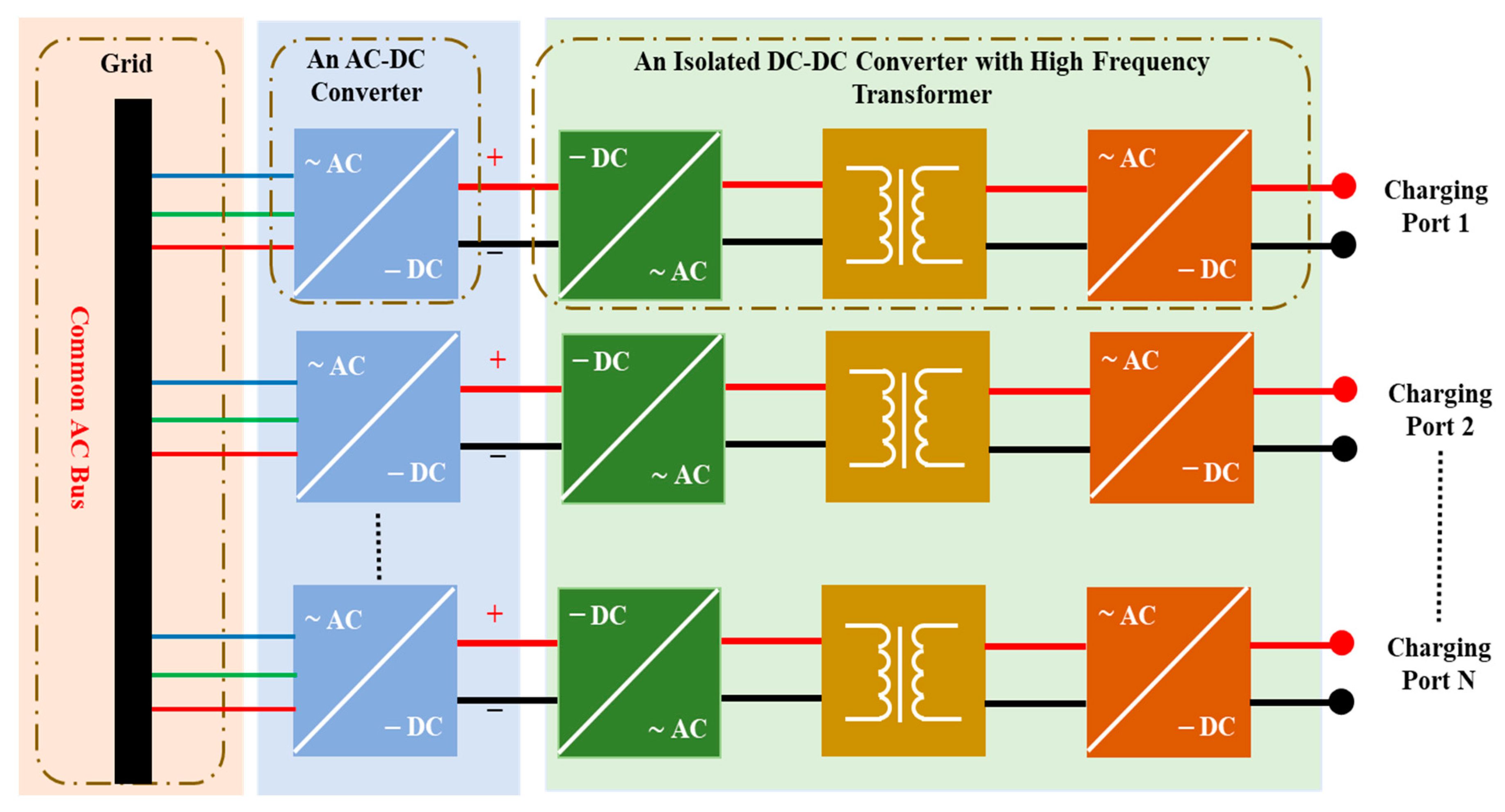
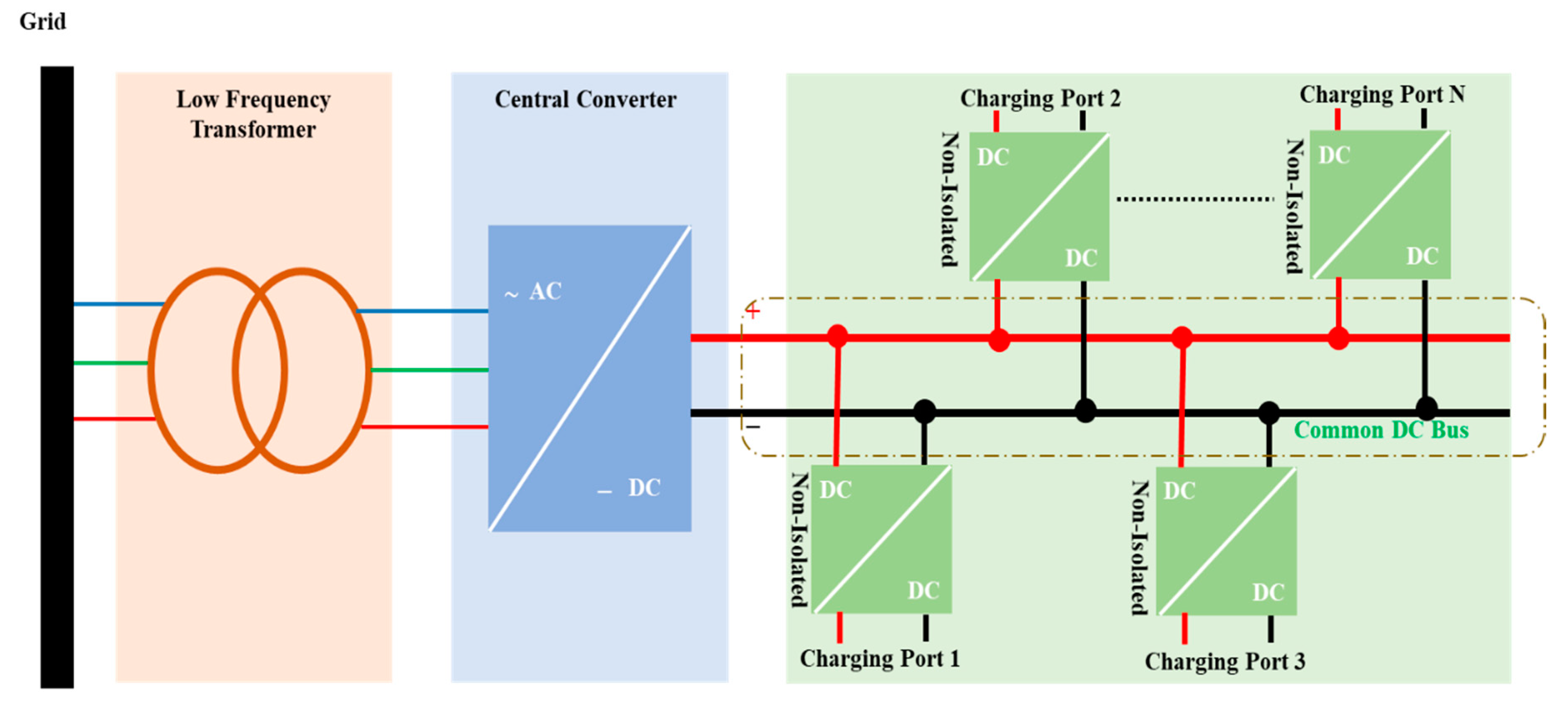
5. Review of Converter Topologies for FCHARs
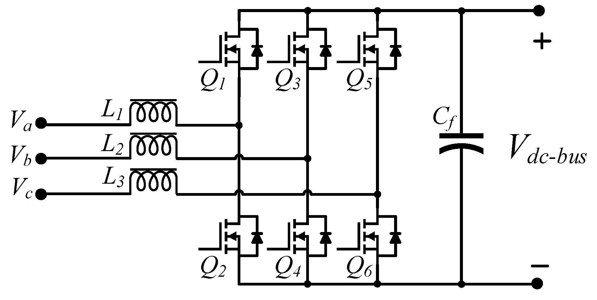
Generally, FCHARs’ architectures are characterized into two types [139,140]. The first one is the common AC-bus architecture, composed of fast chargers each having dedicated AC-DC conversion stages and high-frequency transformers, as shown in Figure 14. The second one is the common DC-bus architecture, which only requires one central AC-DC conversion stage and one low-frequency transformer, as shown in Figure 15. Regarding the possibility of integrating renewable energy sources into the charging stations, the latter architecture exhibits significant advantages due to the absence of synchronization issues of the integrated renewable energy sources. According to the SAE J1772 standard, an FCHARs has DC-bus voltage up to 600 V and DC current up to 550 A to charge EVs in less than ten minutes and the fast charger should be placed outside the EVs [75,76].
There are two types of common DC-bus architecture. One is the unipolar DC-bus, which is compatible with two-level voltage source converters such as three-phase bridgeless boost converter [139], voltage source inverter (VSI) [141], and three-phase Vienna rectifier [142]. The other one is the bipolar DC-bus, which is compatible with a three-level neutral-point clamped (NPC) converter [140]. The common DC-bus architecture of a fast charger consists of three stages, namely an AC-DC rectifier, an input filter and a DC-DC converter. The AC-DC rectifier stage is used to regulate the power factor and create a constant DC voltage for the DC-DC converter. The input filter stage is employed to reduce harmonic currents caused by the AC-DC rectifier stage. The last stage controls the DC charging current for the better response of the DC-DC converter. Several types of AC-DC converter and DC-DC converter for the fast charging application are analyzed in the following sections.

5.1. AC-DC Stage

5.1.1. Three-Level Three-Phase NPC Converter

The three-level three-phase NPC converter as shown in Figure 16, offers high-power capacity and flexible ways for connecting the input sources [140]. It is also able to produce a five-level output voltage in comparison to the VSI converter. This results in a lower dv/dt rating, a smaller filtering requirement, and a better current performance. However, the NPC converter has an inherent issue, which is the imbalanced power between the positive and negative DC-bus; this imbalanced power can lead to producing an inferior grid-side current that can create instability regarding the grid.

5.1.2. Three-Phase Bridgeless Boost Converter

The three-phase bridgeless boost converter, as shown in Figure 17, takes advantages of the boost Power factor correction (PFC) converter. Numerous control schemes of this topology are discussed in literatures such as sliding mode control (SMC) [143], sinusoidal pulse-width modulation (SPWM) [144], hysteresis current control (HCC) [145], space vector modulation (SVM) [146].
Most of these papers favor minimizing the filter size, whereas some focus on reducing the stresses on active devices. Due to the nature of the boost inductor, high power stress is reported for all these control schemes.

5.1.3. Three-Phase Vienna Rectifier

The three-phase Vienna rectifier as shown in Figure 18, has operating principles similar to the three-phase bridgeless boost converter but it uses fewer active switches [147]. The reduction in the number of switches helps to minimize the losses of reverse recovery currents, making it suitable for fast charging. Vienna rectifier is controlled based on regulations of the high-frequency PWM. A critical advantage of this topology is that it exhibits a neutral-connection free. Also, the dead-time problem of the switches can be removed thanks to the diodes taking commutation as soon as the switches turn-off. However, this converter requires a high voltage on the output side. Since one of the three main switches ( Q 1 ,   Q 2   a n d   Q 3 ) remains turned off at all times, this results in the minimum voltage over each filter capacitor ( C 1   o r   C 2 ) being the peak input line-to-line voltage. Thus, the minimum boost voltage required for this converter is twice the line-to-line voltage.

5.2. DC-DC Stage

5.2.1. Multiple Interleaved Buck Converters

The voltage of a common DC-bus structure is normally up to 600 V and higher than the battery voltage which is from 200 V to 450 V. For charging the batteries, a single-phase buck converter can be used. However, in high-current applications, the single-phase buck converter requires a large inductor to keep the inductor current ripples small. The large inductor increases the cost and size of the converter. Instead of using the large inductor, a multi-phase interleaved buck converter as shown in Figure 19, is proposed [148,149,150]. The separate inductors of the multi-phase interleaved buck converter are used to enhance the efficiency of the converter. This converter shares currents between the multi-phase modules. If the number of phases is increased, the size of the inductor decreases as the number of phases is multiplied by the fundamental frequency of each inductor. Despite many advantages, this converter has not become mainstream since it is only compatible with systems that include a front isolated-low-frequency transformer and contains high THD in phase current.

5.2.2. Full-Bridge LLC Resonant Converter

Another potential converter to be used in the DC-DC stage of a fast charger is the Full-Bridge LLC resonant converter (FBLLC) as shown in Figure 20 [151,152,153,154]. The FBLLC resonant converter can achieve high efficiency at high-voltage operations and a full range of ZVS for the primary switches. In addition, since the sinusoidal current waveform is shaped, there is no oscillation voltage on the rectifier diodes and no reverse recovery current.
Despite providing many advantages, the major drawback of this topology is that a wide range of the switching frequency has to be applied to control the output voltage of the battery. This makes the filter and transformer designs much more complicated and the operation of the converter becomes less efficient once the battery voltage is low.

5.2.3. Phase-Shift Full-Bridge Converter

The Phase-shift full-bridge (PSFB) converter is the most popular converter used in high-power applications as shown in Figure 21 [155,156,157,158,159]. PSFB converters have several desirable features such as soft-switching for the primary switches, simple control method, and low current stress on devices. However, PSFB converters have some drawbacks such as high-circulating current in the freewheeling interval and high voltage stress on the rectifier bridge.

6. Evaluation of Emerging Switch Technology for Converters

Presently, switching circuits of DC-DC converter topologies for BEV and PHEV powertrains and fast charger converters are supported by Si-based semiconductors (Si-MOSFETs and Si-IGBTs). In the near future, WBGSs (i.e., SiC and GaN) will replace Si-based semiconductors in automotive industries [160]. From a technical point of view, WBGSs are more suitable for EVs and FCHARs power electronics (PE) converters due to the higher bandgap, larger critical break-down electrical field, higher thermal conductivity (only in SiC), larger electron velocity and lower dielectric constant as illustrated in Figure 22 [95,161,162,163,164,165,166]. These characteristics of WBGSs allow PE converters to operate at a higher frequency (up to 5 GHz), handle much higher voltages (>600 V), and withstand higher temperatures (~300 °C) in comparison to Si [19]. Thus, switches built using WBGSs have reduced switching power losses and are more compact in size since smaller-sized heat sinks are required, in addition to which, the higher frequencies also allow for a reduction in size in the passive components. Therefore, designs based on WBGSs are less costly and more compact. Currently, there are limitations such as a higher price, less maturity, less reliable compared to Si-based semiconductors, lack of packaging and qualification that also limits the potential performance and progress of WBGSs [161,167,168,169].
The performance of PE converter topologies relies highly on switching losses and conduction losses of semiconductor switches, as low power losses in the switching circuit ensure maximum efficiency, high power density, and downsizing the heat sink and coolant circuit size [170,171,172]. In a PE converter, the inductor is the bulkiest component having the largest volume and weight, especially in high power applications. Therefore, downsizing the inductor is the prime target while designing a converter. Inductor size is inversely proportional to switching frequency while switching frequency is directly proportional to switching losses [169,173,174,175]. Therefore, there is a trade-off relation between inductor size and switching losses. However, WBGSs allow the designer to maintain high-switching frequency while keeping lower switching losses and conduction losses and hence, achieving smaller inductor size without a corresponding increase in the switching losses [162,167,169,170,172].
To evaluate the superiority of the SiC-based semiconductors over Si-based semiconductors, two DC-DC converter topologies, including BC and MDIBC, are assessed to measure the converters losses and efficiency. SKM 100GB125DN is used as Si-IGBT and SKM200GB12T4SiC2 is used as SiC for the switching circuit of BC and MDIBC [176,177]. Metglas® Amorphous 2605SA1 is selected as the core material of the inductor to maximize its power density as shown in Figure 23a. This core is suitable for high-frequency and high-power applications due to its low skin effect losses and proximity effect [178]. These inductors are modeled for achieving high power density and reducing weight while obtaining minimal core losses for automotive applications. The core loss response of Metglas® core is improved ~50% with respect to conventional silicon steel as shown in Figure 23b [178].
The specifications of the DC-DC converter remain the same for both converters and are shown in Table 4. The power losses in a DC-DC converter are due to the switching and conduction losses of the active devices, and the conduction and air-gap losses of the passive devices (inductor and capacitor).
Table 5 shows the equations used for the loss calculation of DC-DC converters. Here the IGBT and diode characteristics (rCE, VCE, VCC, IC, Eoff, Eon, rf, Vo, IF and Err) are selected from the SKM 100GB125DN and SKM200GB12T4SiC2 datasheets [176,177]. During the loss model design of DC-DC converters, several factors are assumed to simplify the loss calculation [179]. They are:
(a)
The temperature effect on semiconductor devices is not considered.
(b)
The loss due to the skin effect of the inductor is also neglected.
(c)
The parasitic capacitance loss and loss in PCB are also neglected.
Figure 24 depicts the comparative performance map of BC and MDIBC using Si and SiC semiconductor. As mentioned in the previous section MDIBC efficiency is higher than BC for the same specification at 20 kHz, which is respectively 89.92% and 86.69% while using a Si-based semiconductor, and 96.82% and 93.88% while using SiC-based semiconductor. That’s an improvement of 6.9% and 7.2% in the efficiency of SiC over Si at the 20 kHz switching frequency for both BC and MDIBC. Furthermore, as can be seen from the figure, the reduction in efficiency is less significant when the switching frequency is increased for SiC as compared to Si, where Si losses more than 5%–10% efficiency as the switching frequency is increased from 20 kHz to 80 kHz, while SiC losses are between 1% and 3% respectively.
Figure 25 illustrates the distribution of power losses for both Si and SiC-based BC and MDIBC. It has been found that the switching and conduction losses are higher in Si-based converter whereas these losses are highly reduced in the SiC-based converter. Not only that, the switching losses in Si-based converters increases significantly with switching frequency, quickly eclipsing all other losses. As switching losses are very high for 60 kHz and 80 kHz frequency, it demonstrates that the Si-based converters cannot tolerate such high thermal stresses. However, as a share of the losses, the core and conduction losses are more significant in the SiC-based converter, as an increase in the AC loss is expected in the windings and the core due to higher switching frequency. From these results, it is proved that the low turn-on and turn-off characteristics of the SiC-IGBTs and the low recovery-loss characteristics in the SiC-Diode helps to improve the overall efficiency of the converters for BEV and PHEV powertrains.

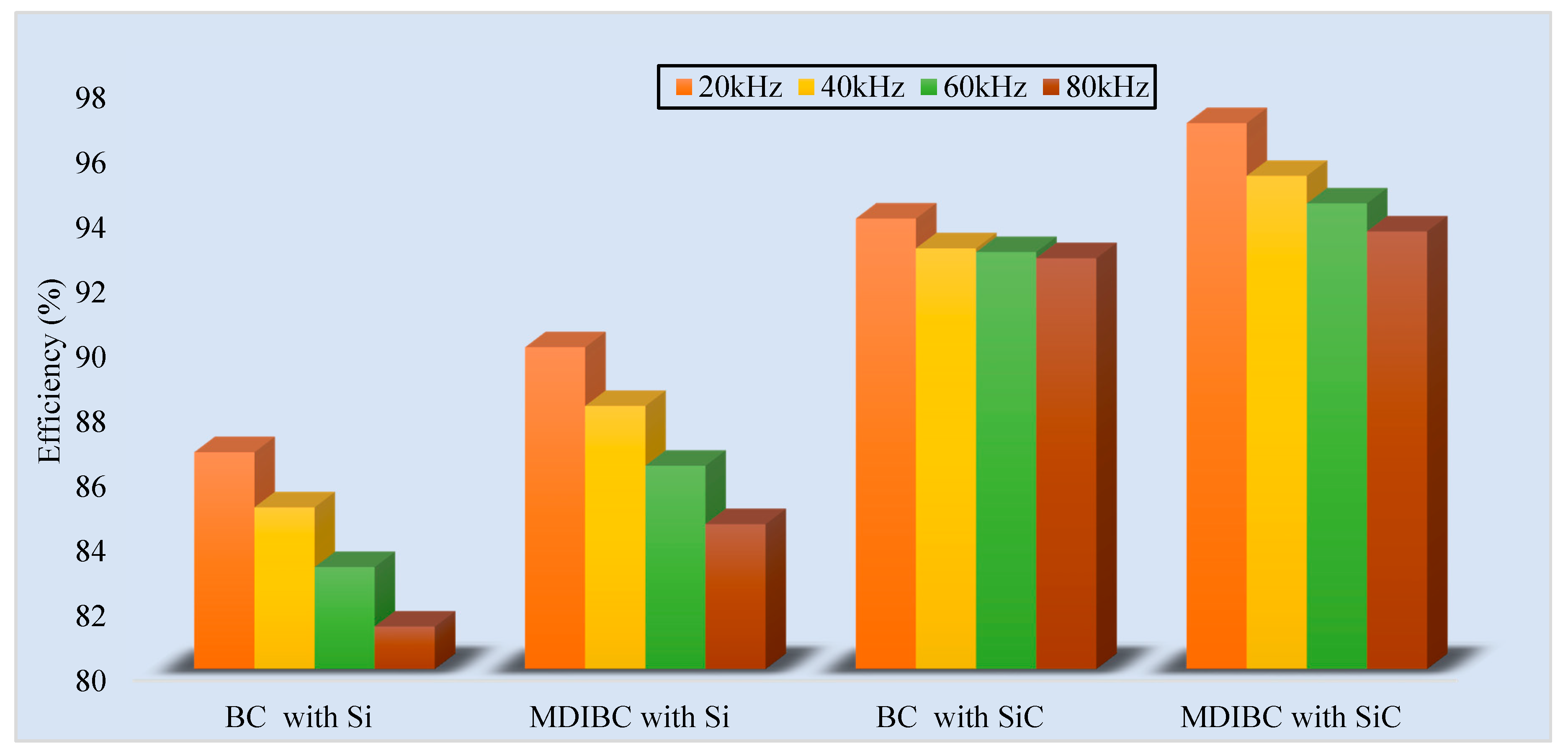
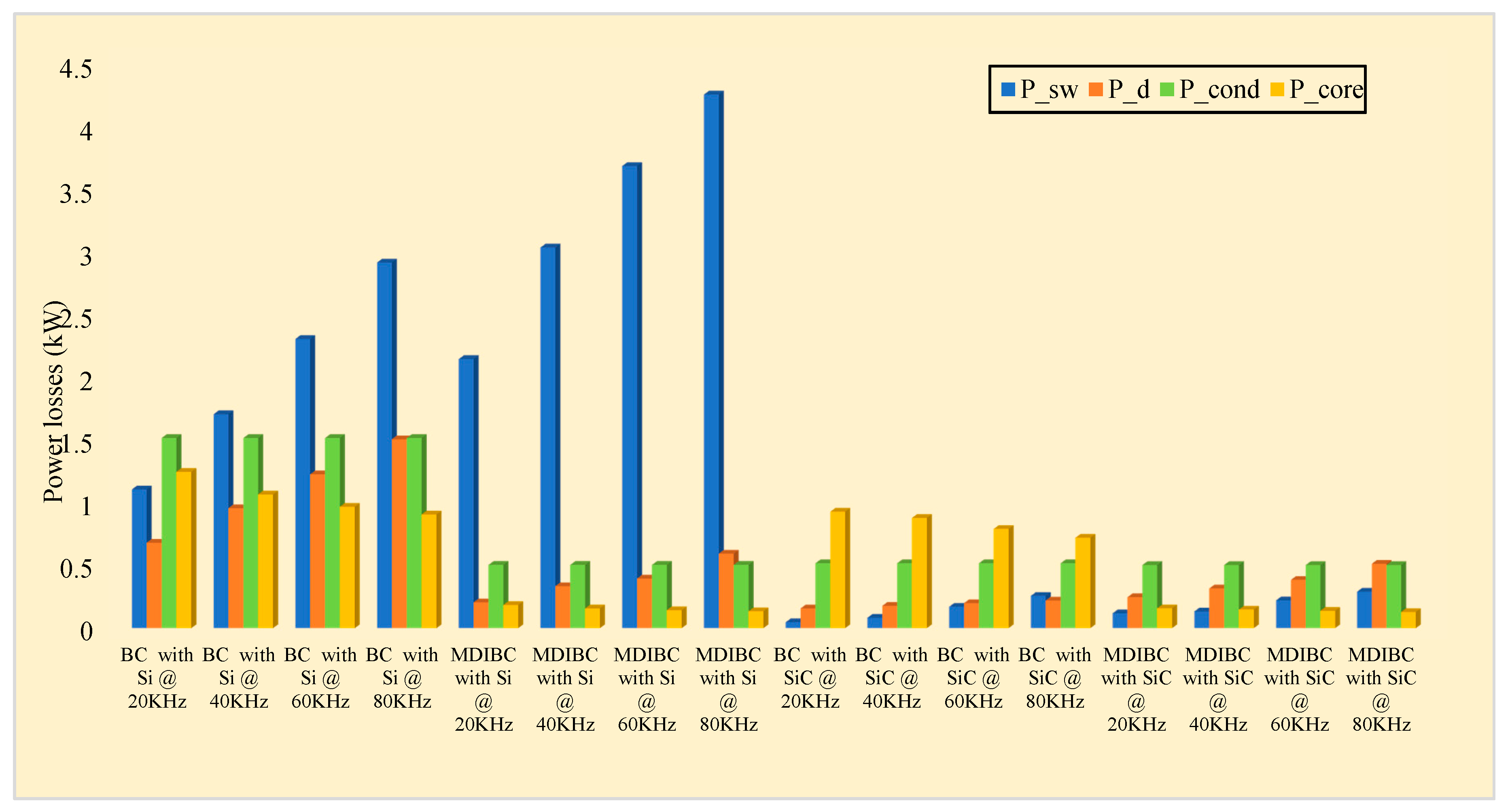
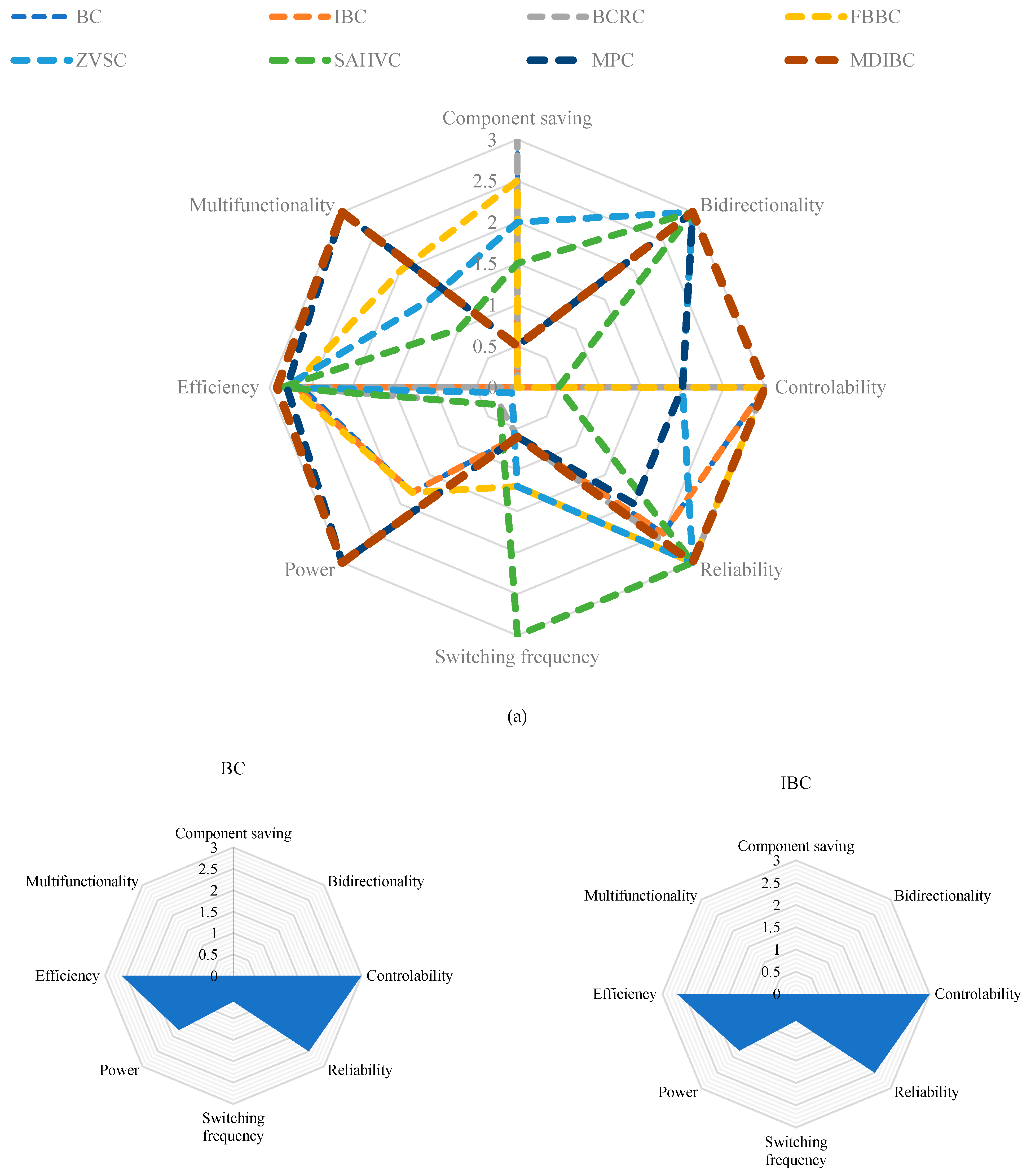
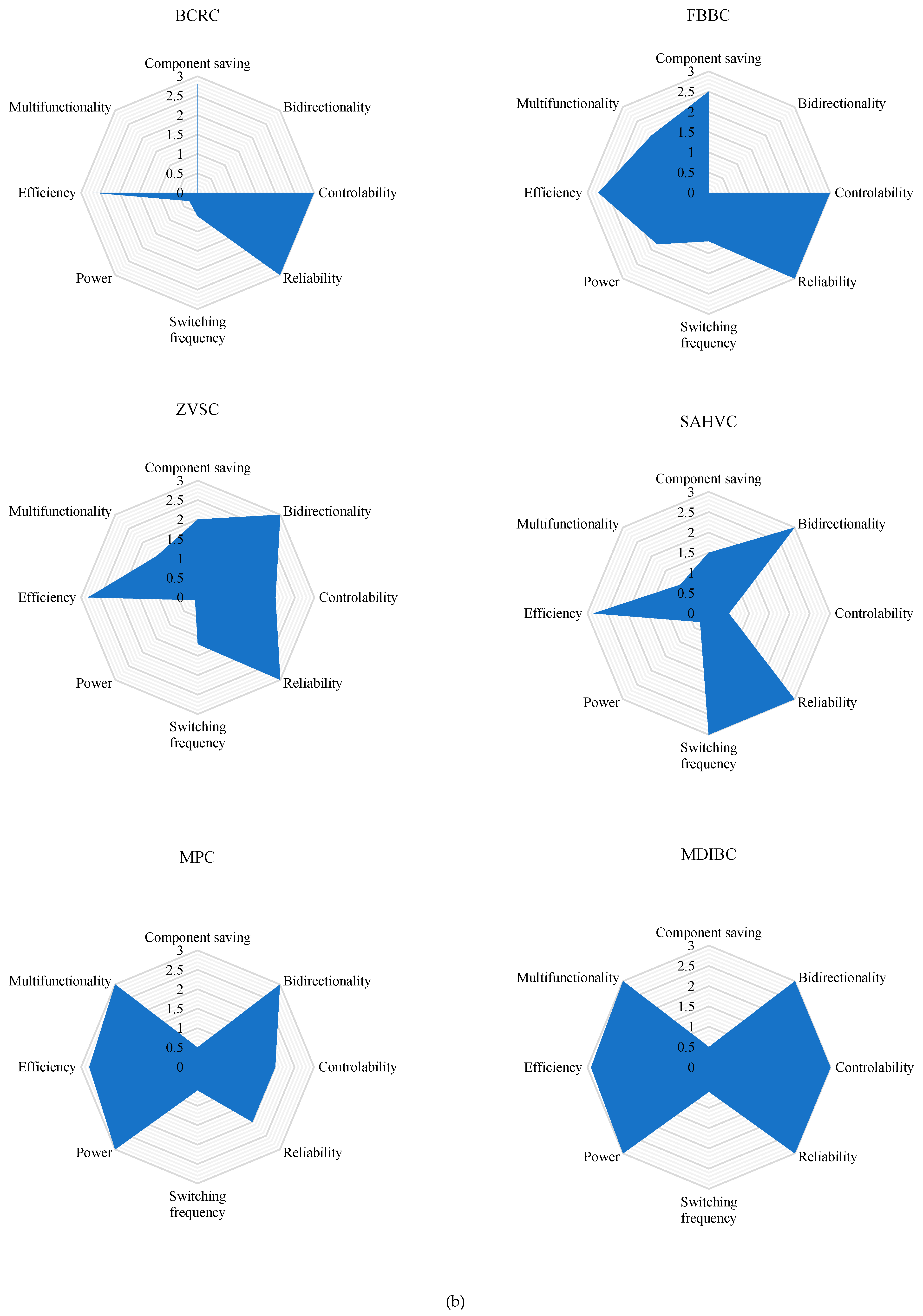
7. Comparative Analysis and Discussion

Table 6 presents a qualitative features comparison of the discussed converters. A total of seven features are evaluated for eight different converters. Single polarity output voltage can be found in BC, IBC and BCRC. The complexity of designing the control system remains simple for BC and IBC, moderate for BCRC and FBC, whereas for all the other converters it becomes complex. High power conversion is not appropriate for BCRC, ZVSC and SAHVC. The input current ripple and output voltage ripple is low for IBC, MPC and MDIBC, moderate/medium for ZVSC and SAHVC, and for all the other cases it is low. The EMI suppression is decreased for IBC, BCRC, ZVSC, SAHVC, and MDIBC, while it is required for FBC and MPC. The rest of them are easily identified. Switching frequency is high only for SAHVC and moderate for FBC. Multiple input port feature is only present in MDIBC and MPC, for the rest of the converters, it is absent.
Table 7 shows a modest component comparison between these eight converters topologies reviewed in this paper. The expected cost of the DC-DC converters for BEVs and PHEVs are also a vital issue for designing a system. A relative cost can be projected based on the component count as number of switches, diodes, capacitors, transformers and inductors used in the different DC-DC converter topologies. According to that, the estimated cost is low for BC and BCRC as in both topologies a lower number of components is used. The price is moderate for IBC, FBC, ZVSC and MDIBC as the component counts are high, and HFT or multiple inductors are used in those converters. In the estimation, the converter topologies using complex control and switching circuit are considered as a high-cost category, such as MPC and SAHVC. FBC, ZVSC and SAHVC provide galvanic isolation. According to the data, voltage gain is low for SAHVC and approximately the same for the rest of all topologies.
Table 8 provides a qualitative analysis of the discussed DC-DC converters for BEVs and PHEVs. BC’s specialty is that it requires a simple control system. The EMI requirement is also simple. As the overall circuitry is simple, it has a feature of cost-effectiveness, but the use of larger capacitor increases volume and it is not appropriate for high power conversion. Both IBC and FBC display the possibility of the high efficiency of about 92% at full load condition [49]. Current ripples are negligible, but switching losses are present in IBC, and FBC’s volume increases because of the usage of the high-frequency transformer with the inductor. The need for EMI suppression is present for both the converters. For the BCRC, its size and weight are reduced since large heat sink is not required; however, it is only capable of handling low power. In isolated ZVSC, switching losses are negligible as high frequency and power processing is provided, and EMI factor is decreased, thus power density increases; however, these gates have high current ratings and flow of low power is not suitable. SAHVC provides noise-free operation by the high spectral purity of mode symmetry, minimized output impedance helps increase efficiency, has control technique of critical nature, and the switches can endure high voltage stress; it is suitable for low power BEVs. MPC has minimum voltage & current ripples, an efficiency of 97% at 30kW load, but EMI suppression is needed, reliability is low, and it requires a robust synchronization process. The MDIBC topology differs from the other DC-DC converters as high output voltage level can be maintained without increasing the volume of passive components. Moreover, at MDIBC the interleaving technique makes it possible to share current between switching gates, so there is less stress on the switches. Therefore, the current rating of switches is low, and it increases the reliability of the system. However, this topology is sensitive to duty cycle change at load step, and the number of components is high.
In addition, this review paper develops a comprehensive visual comparison shown in Figure 26. The visual comparison parameters are normalized from the actual values into a standard 3-point Likert scale. The normalized formula is derived as follows [180]:
N = x + [ ( R L ) ( y x ) ( H L ) ]
where N = normalized value, R = real value, y = 3 (highest value in 3-point scale), x = 0 (lowest value in 3-point scale), H = highest real value, L = lowest real value.
Numerous insights have been found from the visual comparison of DC-DC converter topologies. The power conversion efficiency of SAHVC and MDIBC are higher at full load condition. Controllability is low in SAHVC, moderate in MPC and ZVSC, and high in the rest of the topologies. Bidirectionality is high in MDIBC and MPC, moderate in ZVSC and SAHVC. Reliability is low in MPC, moderate in BC and IBC, and high in the rest of the topologies. Power range is high in MDIBC, MPC, BC, IBC and FBC, and low in the other topologies. All these benefits make MDIBC a lucrative converter topology for high power BEVs and PHEVs. However, for low-power BEVs and PHEVs SAHVC, BCRC and ZVSC show similar performance features in most aspects and have competence according to design demand and converter capacity.
Table 9 illustrates a qualitative analysis of the discussed converter topology for FCHARs. In the AC-DC stage converter, 3-phase bridgeless boost converter has a minimal number of components whereas in the DC-DC stage converter all the converters are using a quite the same number of components. In terms of control, the 3-phase Vienna rectifier requires a straightforward control technique than other converter topologies in the AC-DC stage and FBLLC resonant converter has a complicated control technique compared to other converter topologies in the DC-DC stage. Both 3-level 3-phase NPC and FBLLC resonant converter provide less stress in the switching circuit and are capable of high-power conversion. Both 3-phase Vienna rectifier and Multiple interleaved buck converter have a simple architecture with higher efficiency and reliability. However, Multiple interleaved buck converter contains high phase current THD, which makes the topology less convenient.

8. Future Research Trends

This section will offer an informed analysis of what can be expected of DC-DC converters in the coming years—the key parameters that will be considered for the study, including the material used for the switching of DC-DC converters drive circuit, the DC-DC converters modeling and control techniques and the estimated power density growth of DC-DC converters.

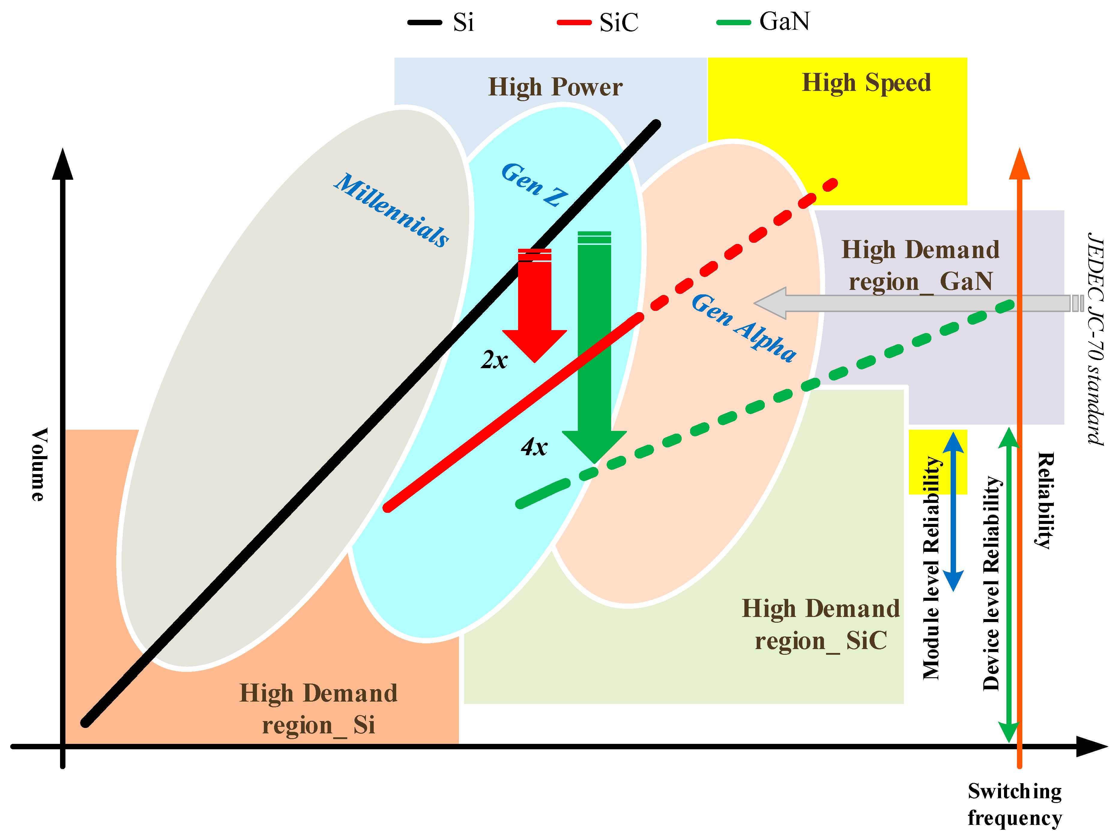
8.1. WBG Semiconductor Components

It is clear from the review that the DC-DC converters are tending towards high switching speed as this is related to decreased power losses in the passive components. Thus, semiconductor materials that aid in achieving higher switching speed without a corresponding increase in thermal losses are preferable. Thus, WBGS materials are quickly becoming the mainstay of high-power and high-speed power electronics applications. SiC and GaN are quickly becoming commercially viable as alternatives to Si as the material to construct future power electronics devices. GaN supports higher speed switching of less-power electronic devices and SiC supports higher power density and less cooling requirements than Si-only switches [181].
Currently, SiC is seeing intense research and market capitalization due to the ever-present demand for handling higher voltage and current in switches without the need for elaborate heat dissipation mechanisms. In fact, according to the white paper by Yole Development [92], it is projected that the adoption of SiC-based devices will see a tipping point in terms of market share in 2020. Figure 27 shows the various applications where SiC-based devices will see widespread usage. As can be seen, the core application of SiC will be in PV-based inverters to be used in solar farms for electricity generation. Worldwide, there has been an exponential increase in solar power plants, with the generation capacity exceeding 500 GW in 2018 [182]. Besides solar farms, SiC will see increasing usage in rail lines, EVs/HEVs, and xEV charging infrastructure. xEV refers to the system of battery replacement in electric vehicles in charging stations, where instead of charging a battery, the discharged battery is replaced with a fully charged one to save time.
According to the Yole report, today low voltage (<900 V) applications still constitute the lion’s share of the power electronics market, but the proportion of medium (1 kV~2 kV) and high voltage (2 kV~4 kV) applications it is projected to increase by 2025, by when the power electronics market size is projected to exceed $21 billion, a leap of 25% from current levels [183,184]. WBGSs are already competing with Si and with each other in the region where switching power exceeds 1 kW, or switching frequencies exceed 100 kHz, including in the construction of high-power modules such as IGBTs and MOSFETs [93]. Whereas in 2017, the applications of SiC were dominated by PV and PFC, from 2019 onwards EVs will become the leading applications for SiC modules [160,185]. On the other hand, GaN will mainly be used in data centers, fast chargers, and wireless chargers, but its usage and adoption will lag SiC due to a lack of maturity [186]. Manufacturers prefer systems that are cost-effective and reliable, regardless of whether such systems are silicon-based or WBGS based. This is presently the main barrier to entry of WBGSs into the market, and why Si is still the dominant player, and why GaN is lagging SiC in market adoption. WBGSs may certifiably perform better than Si by as much as ~2x for SiC and ~4x for GaN, but Si has almost five decades of market exposure, and its reliability has been proven [183,186]. On the other hand, SiC still faces questions about long term reliability. SiC first appeared on the market in the turn of the century with the SiC diode, and the first SiC MOSFET was available ten years later. Since then SiC devices have been undergoing device level and module level focus on their reliability. The JEDEC JC-70 standard will soon (~2019) determine the standard test condition at the device level for all manufacturers [92]. In addition, SiC needs to establish its supply chain in terms of wafer fabrication to meet growing demand [92,183,184].These trends are summarized in Figure 28 which shows the adoption rates of different types of power electronics devices by different segments of the society, based on when different semiconductors became widespread. Millennials are considered the silicon generation, as they lived during times when the use of Si-based semiconductors grew exponentially. In contrast, Gen Z is currently reaching adulthood at a time when SiC-based semiconductors are maturing, and applications based on SiC are growing. However, by the time GaN matures and sees widespread adoption, it will be the time of Generation Alpha [92,184,186,187].

8.2. Emerging Modeling and Control Techniques

This paper reviews many different DC-DC converter topologies currently in use in BEV and PHEV powertrains and in FCHARs. However, the future trends of DC-DC converter research will aim to address the following key issues: electrical optimization of the design methods using WBGSs based topology to fully utilize their high-temperature, high-frequency, and low-loss characteristics [188]; mechanical optimization design methods to further improve efficiency, power density, modularity, and reliability; and a trend towards high-fidelity, multi-functionality, scalability, modularity, and using intelligent control and management techniques to achieve high efficiency and power density [189]. Electrical and mechanical design aside, there are various control and optimization techniques being applied to the controller design including model predictive control, fuzzy logic control, artificial neural network control and various genetic algorithms to optimize different parameters of the converter [189]. Moreover, the high-fidelity model of DC-DC converter aims to design, validate and publish a recommendation about standard interfaces for next-generation developers [124]. Also, the trend is toward building a modular design methodology to enable scalability in the power handling capability of the converter for different application requirements [189]. Converters have become more multifunctional over time with now bidirectionality, multi-phase, and multi-level becoming common design techniques, with newer techniques in the pipeline. Finally, reliability has become a vital issue the in power electronic design process [190] and with standards such as ISO26262 setting the benchmark in functional safety requirements.

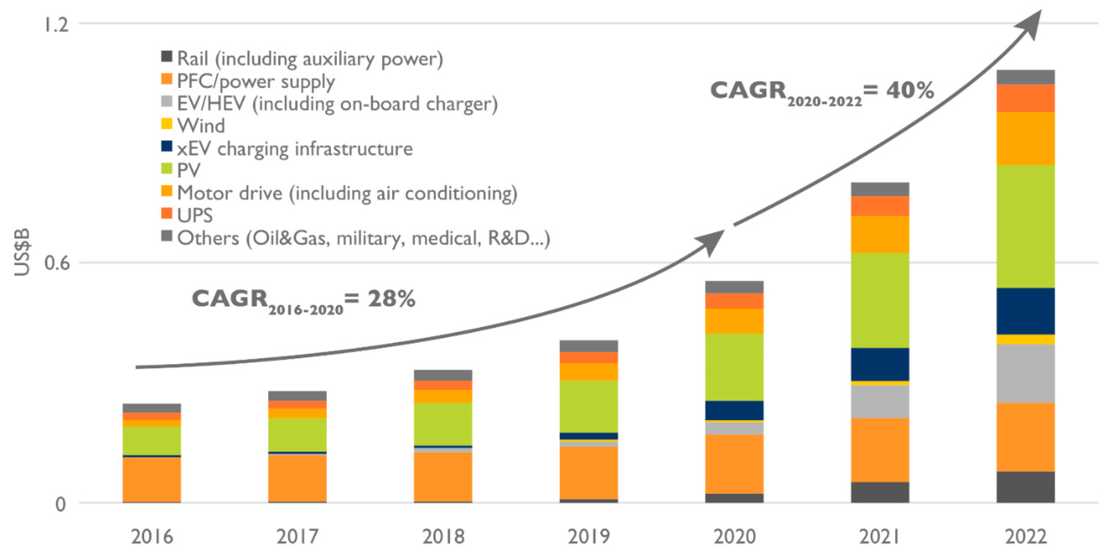
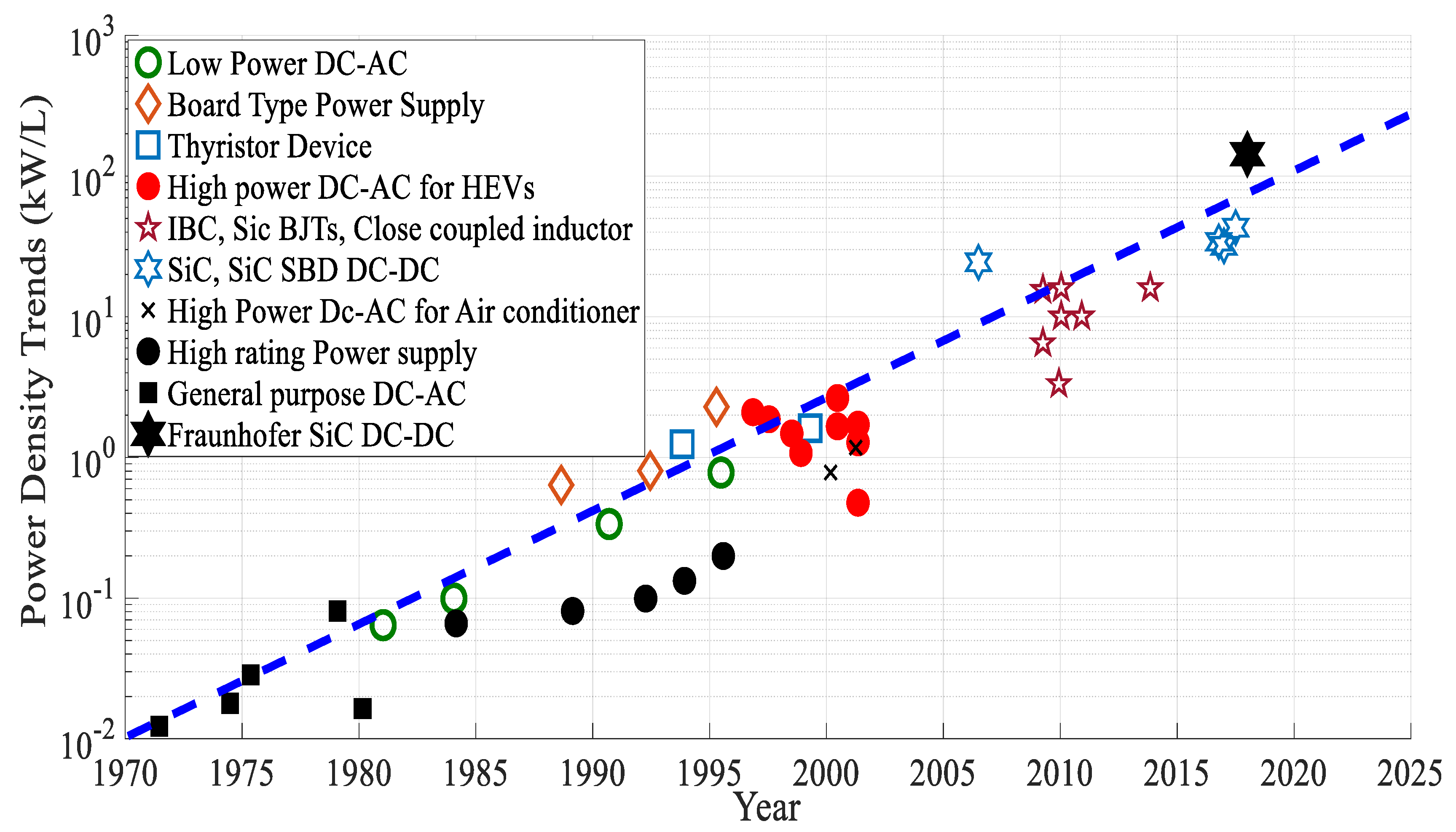
8.3. Projected Power Density Growth of DC-DC Converter

The final trend that will be analyzed will be the evolving applications and power density of DC-DC converters. From [51], it is seen that DC-DC converters will soon be used in the utility and industrial sector including high voltage DC links, high power DC supply units, and solar (PV) farms, in the transportation industry, especially electric trains and EVs, and in physics research such as particle accelerators and synchrotrons. These are applications where the typical power output of the DC-DC converter exceeds 20 kW and operates in the 2 kV+ range. To achieve such power levels converters are constructed with increasing power density as shown in Figure 29. The figure shows projected power densities of 100 kW/L by the year 2020 [170]; however, currently a Full SiC 200 kW, 300 A DC-DC converter prototype having a power density of 143 kW/L has already been demonstrated by Fraunhofer.

9. Conclusions

For the very first time, this paper presents the state of art reviews of the design and evaluation of DC-DC converter topologies for BEV and PHEV powertrains and converter topologies for FCHARs, including future trends of research. This review has given a focus on multiple performance features, such as output power, component count, switching frequency, electromagnetic interference (EMI), losses, effectiveness, cost and reliability which directly influence the selection of a particular DC-DC converter for respective BEV and PHEV powertrains. This paper will also guide automotive engineers and PE converter designers to select passive components (i.e., capacitors, inductors) precisely based on powertrains demand.
It can be seen from this review that the MDIBC can be a better option if one has to integrate two or more energy sources in the BEV and PHEV powertrains. To conclude, the MDIBC is the best option for mainly high-power BEVs and PHEVs for having very low input current ripples and output voltage ripples, bidirectionality, low EMI, high efficiency as well as reliability, and moderate cost and compact size or volume. On the other hand, the SAHVC, ZVSC and BCRC are suitable for low-power BEVs and PHEVs, as all of them have smooth starting, soft switching capability, low EMI, low switching losses and high efficiency.
In case of FCHARs, the Vienna rectifier is the favored option from the AC-DC stage configuration, due to its high-power factor and high output current harmonics cancellation capability in high power applications. In case of the DC-DC stage, the Multiple interleaved buck converter depicts better response, due to its high efficiency, simple control technique and design process, although high phase current THD make this topology inefficient.
Finally, with the recent advancement of WBGSs technologies, PE converters could experience significant improvement in their power density, cost and longevity. The WBGSs can significantly reduce the switching losses at high-switching frequencies, which enables the PE converter topologies to improve overall system efficiency further. Therefore, the EV powertrains roadmap is tending towards the compact PE converters solution to improve the energy efficiency and reliability, while reducing the cost using WBGSs instead of Si.

Author Contributions

S.C. reviewed and designed the selected the topologies of DC-DC converter for EVs and PHEVs and wrote the first version of the paper; H.-N.V. reviewed the converter topologies for fast charging system; M.M.H. contributed in reviewing the future research scopes; D.D.-T. contributed in modeling and improved the structure of the paper; M.E.B. contributed in analyzing the results and editing the paper; O.H. reviewed and edited the manuscript and also supervised this research study.

Funding

This project (HiFi-Elements) has received funding from the European Union’s Horizon 2020 research and innovation program under Grant Agreement no. 769935. Energies 12 01569 i001

Acknowledgments

Authors acknowledge Flanders make for the support to this research group.

Conflicts of Interest

The authors declare no conflict of interest.

References

  1. EEA. Total Greenhouse Gas Emissions by Sector (%); European Environment Agency: Copenhagen, Denmark, 2017. [Google Scholar]
  2. Fontaras, G.; Zacharof, N.-G.; Ciuffo, B. Fuel consumption and CO2 emissions from passenger cars in Europe—Laboratory versus real-world emissions. Prog. Energy Combust. Sci. 2017, 60, 97–131. [Google Scholar] [CrossRef]
  3. Fontaras, G.; Dilara, P. The evolution of European passenger car characteristics 2000–2010 and its effects on real-world CO2 emissions and CO2 reduction policy. Energy Policy 2012, 49, 719–730. [Google Scholar] [CrossRef]
  4. European Commission. Communication from the Commission to the Council and the European Parliament Strategy for Reducing Heavy-Duty Vehicles’ Fuel Consumption and CO2 Emissions; European Commission: Brussels, Belgium, 2014. [Google Scholar]
  5. EEA. CO2 Emission Report; European Environment Agency: Copenhagen, Denmark, 2017. [Google Scholar]
  6. European Commission. A European Strategy for Low-Emission Mobility, SWD 244 Final; European Commission: Brussels, Belgium, 2016. [Google Scholar]
  7. Yunus, M. A World of Three Zeros: The New Economics of Zero Poverty, Zero Unemployment, and Zero Net Carbon Emissions; Public Affairs: New York, NY, USA, 2017; ISBN 978-1478992004. [Google Scholar]
  8. Thiel, C.; Perujo, A.; Mercier, A. Cost and CO2 aspects of future vehicle options in Europe under new energy policy scenarios. Energy Policy 2010, 38, 7142–7151. [Google Scholar] [CrossRef]
  9. Rezvani, Z.; Jansson, J.; Bodin, J. Advances in consumer electric vehicle adoption research: A review and research agenda. Transp. Res. Part D Transp. Environ. 2015, 34, 122–136. [Google Scholar] [CrossRef] [Green Version]
  10. Chan, C.C. The state of the art of electric, hybrid, and fuel cell vehicles. Proc. IEEE 2007, 95, 704–718. [Google Scholar] [CrossRef]
  11. Lebeau, K.; Van Mierlo, J.; Lebeau, P.; Mairesse, O.; Macharis, C. The market potential for plug-in hybrid and battery electric vehicles in Flanders: A choice-based conjoint analysis. Transp. Res. Part D Transp. Environ. 2012, 17, 592–597. [Google Scholar] [CrossRef]
  12. Pang, C.; Dutta, P.; Kezunovic, M. BEVs/PHEVs as Dispersed Energy Storage for V2B Uses in the Smart Grid. IEEE Trans. Smart Grid 2012, 3, 473–482. [Google Scholar] [CrossRef]
  13. Al-Alawi, B.M.; Bradley, T.H. Total cost of ownership, payback, and consumer preference modeling of plug-in hybrid electric vehicles. Appl. Energy 2013, 103, 488–506. [Google Scholar] [CrossRef]
  14. Al-Alawi, B.M.; Bradley, T.H. Review of hybrid, plug-in hybrid, and electric vehicle market modeling Studies. Renew. Sustain. Energy Rev. 2013, 21, 190–203. [Google Scholar] [CrossRef]
  15. Asazawa, K.; Yamada, K.; Tanaka, H.; Oka, A.; Taniguchi, M.; Kobayashi, T. A Platinum-Free Zero-Carbon-Emission Easy Fuelling Direct Hydrazine Fuel Cell for Vehicles. Angew. Chemie 2007, 119, 8170–8173. [Google Scholar] [CrossRef]
  16. Hadley, S.W.; Tsvetkova, A.A. Potential Impacts of Plug-in Hybrid Electric Vehicles on Regional Power Generation. Electr. J. 2009, 22, 56–68. [Google Scholar] [CrossRef] [Green Version]
  17. Romm, J. The car and fuel of the future. Energy Policy 2006, 34, 2609–2614. [Google Scholar] [CrossRef]
  18. Thomas, C.E. Fuel cell and battery electric vehicles compared. Int. J. Hydrogen Energy 2009, 34, 6005–6020. [Google Scholar] [CrossRef] [Green Version]
  19. Hawes, M. Emerging Solutions to Hybrid & Electric Vehicle DC:DC Converter Design and Test; Keysight Technologies: Santa Rosa, CA, USA, 2017. [Google Scholar]
  20. Bradley, T.H.; Frank, A.A. Design, demonstrations and sustainability impact assessments for plug-in hybrid electric vehicles. Renew. Sustain. Energy Rev. 2009, 13, 115–128. [Google Scholar] [CrossRef]
  21. Emadi, A.; Lee, Y.J.; Rajashekara, K.; Emadi, A.; Lee, Y.J.; Rajashekara, K. Power Electronics and Motor Drives in Electric, Hybrid Electric, and Plug-In Hybrid Electric Vehicles. IEEE Trans. Ind. Electron. 2008, 55, 2237–2245. [Google Scholar] [CrossRef]
  22. Ehsani, M.; Yimin, G.; Miller, J.M. Hybrid Electric Vehicles: Architecture and Motor Drives. Proc. IEEE 2007, 95, 719–728. [Google Scholar] [CrossRef]
  23. Quinn, C.; Zimmerle, D.; Bradley, T.H. The effect of communication architecture on the availability, reliability, and economics of plug-in hybrid electric vehicle-to-grid ancillary services. J. Power Sources 2010, 195, 1500–1509. [Google Scholar] [CrossRef]
  24. Ehsani, M.; Gao, Y.; Longo, S.; Ebrahimi, K. Modern Electric, Hybrid Electric, and Fuel Cell Vehicles, 3rd ed.; CRC Press: Boca Raton, FL, USA, 2004. [Google Scholar]
  25. Sandy Thomas, C.E. Transportation options in a carbon-constrained world: Hybrids, plug-in hybrids, biofuels, fuel cell electric vehicles, and battery electric vehicles. Int. J. Hydrogen Energy 2009, 34, 9279–9296. [Google Scholar] [CrossRef]
  26. Pollet, B.G.; Staffell, I.; Shang, J.L. Current status of hybrid, battery and fuel cell electric vehicles: From electrochemistry to market prospects. Electrochim. Acta 2012, 84, 235–249. [Google Scholar] [CrossRef]
  27. Fotouhi, A.; Auger, D.J.; Propp, K.; Longo, S.; Wild, M. A review on electric vehicle battery modelling: From Lithium-ion toward Lithium–Sulphur. Renew. Sustain. Energy Rev. 2016, 56, 1008–1021. [Google Scholar] [CrossRef]
  28. Manzetti, S.; Mariasiu, F. Electric vehicle battery technologies: From present state to future systems. Renew. Sustain. Energy Rev. 2015, 51, 1004–1012. [Google Scholar] [CrossRef]
  29. Jin, K.; Ruan, X.; Yang, M.; Xu, M. A Hybrid Fuel Cell Power System. IEEE Trans. Ind. Electron. 2009, 56, 1212–1222. [Google Scholar] [CrossRef]
  30. Moura, S.J.; Fathy, H.K.; Callaway, D.S.; Stein, J.L. A Stochastic Optimal Control Approach for Power Management in Plug-In Hybrid Electric Vehicles. IEEE Trans. Control Syst. Technol. 2011, 19, 545–555. [Google Scholar] [CrossRef]
  31. Nelson, R.F. Power requirements for batteries in hybrid electric vehicles. J. Power Sources 2000, 91, 2–26. [Google Scholar] [CrossRef]
  32. Winter, M.; Brodd, R.J. What Are Batteries, Fuel Cells, and Supercapacitors? Chem. Rev. 2004, 104, 4245–4270. [Google Scholar] [CrossRef] [PubMed] [Green Version]
  33. Offer, G.J.; Howey, D.; Contestabile, M.; Clague, R.; Brandon, N.P. Comparative analysis of battery electric, hydrogen fuel cell and hybrid vehicles in a future sustainable road transport system. Energy Policy 2010, 38, 24–29. [Google Scholar] [CrossRef] [Green Version]
  34. Thounthong, P.; Raël, S.; Davat, B. Energy management of fuel cell/battery/supercapacitor hybrid power source for vehicle applications. J. Power Sources 2009, 193, 376–385. [Google Scholar] [CrossRef]
  35. White Paper. Ultracapacitor Applications for Uninterruptible Power Supplies (Ups); Skeleton Technologies GmbH: Großröhrsdorf, Germany, 2017. [Google Scholar]
  36. Naseri, F.; Farjah, E.; Ghanbari, T. An Efficient Regenerative Braking System Based on Battery/Supercapacitor for Electric, Hybrid and Plug-In Hybrid Electric Vehicles with BLDC Motor. IEEE Trans. Veh. Technol. 2017, 66, 3724–3738. [Google Scholar] [CrossRef]
  37. Campanari, S.; Manzolini, G.; Garcia de la Iglesia, F. Energy analysis of electric vehicles using batteries or fuel cells through well-to-wheel driving cycle simulations. J. Power Sources 2009, 186, 464–477. [Google Scholar] [CrossRef]
  38. Gao, W. Performance Comparison of a Fuel Cell-Battery Hybrid Powertrain and a Fuel Cell-Ultracapacitor Hybrid Powertrain. IEEE Trans. Veh. Technol. 2005, 54, 846–855. [Google Scholar] [CrossRef]
  39. Khaligh, A.; Li, Z. Battery, ultracapacitor, fuel cell, and hybrid energy storage systems for electric, hybrid electric, fuel cell, and plug-in hybrid electric vehicles: State of the art. IEEE Trans. Veh. Technol. 2010, 59, 2806–2814. [Google Scholar] [CrossRef]
  40. Anghel, V. Prediction Failure for Pem Fuel Cells. Int. J. Adv. Eng. Technol. 2012, 4, 1–14. [Google Scholar]
  41. Azib, T.; Bethoux, O.; Remy, G.; Marchand, C.; Berthelot, E. An Innovative Control Strategy of a Single Converter for Hybrid Fuel Cell/Supercapacitor Power Source. IEEE Trans. Ind. Electron. 2010, 57, 4024–4031. [Google Scholar] [CrossRef]
  42. Dotelli, G.; Ferrero, R.; Gallo Stampino, P.; Latorrata, S.; Toscani, S. Supercapacitor Sizing for Fast Power Dips in a Hybrid Supercapacitor—PEM Fuel Cell System. IEEE Trans. Instrum. Meas. 2016, 65, 2196–2203. [Google Scholar] [CrossRef]
  43. Li, B.; Gao, X.; Li, J.; Yuan, C. Life Cycle Environmental Impact of High-Capacity Lithium Ion Battery with Silicon Nanowires Anode for Electric Vehicles. Environ. Sci. Technol. 2014, 48, 3047–3055. [Google Scholar] [CrossRef]
  44. Kolli, A.; Gaillard, A.; De Bernardinis, A.; Bethoux, O.; Hissel, D.; Khatir, Z. A review on DC/DC converter architectures for power fuel cell applications. Energy Convers. Manag. 2015, 105, 716–730. [Google Scholar] [CrossRef]
  45. Lundmark, S.T.; Alatalo, M.; Thiringer, T.; Grunditz, E.A. Vehicle Components and Configurations. Systems Perspectives on Electromobility. 2013, pp. 22–32. Available online: http://publications.lib.chalmers.se/records/fulltext/211435/local_211435.pdf (accessed on 22 April 2019).
  46. Lai, C.M. Development of a novel bidirectional DC/DC converter topology with high voltage conversion ratio for electric vehicles and DC-microgrids. Energies 2016, 9, 410. [Google Scholar] [CrossRef]
  47. Wang, Z.; Liu, B.; Zhang, Y.; Cheng, M.; Chu, K.; Xu, L. The chaotic-based control of three-port isolated bidirectional DC/DC converters for electric and hybrid vehicles. Energies 2016, 9, 83. [Google Scholar] [CrossRef]
  48. Ovidiu, P.; Serban, L. Modeling of DC-DC Converters. In Matlab-Modelling, Programming and Simulations; IntechOpen: London, UK, 2010; pp. 125–150. [Google Scholar]
  49. Al Sakka, M.; Van Mierlo, J.; Gualous, H. DC/DC Converters for Electric Vehicles, Electric Vehicles. Electr. Veh. Model. Simul. 2011. [Google Scholar] [CrossRef]
  50. Kabalo, M.; Blunier, B.; Bouquain, D.; Miraoui, A. State-of-the-art of DC-DC converters for fuel cell vehicles. In Proceedings of the 2010 IEEE Vehicle Power and Propulsion Conference, Lille, France, 1–3 September 2010; pp. 1–6. [Google Scholar]
  51. Forouzesh, M.; Siwakoti, Y.P.; Gorji, S.A.; Blaabjerg, F.; Lehman, B. Step-Up DC-DC converters: A comprehensive review of voltage-boosting techniques, topologies, and applications. IEEE Trans. Power Electron. 2017, 32, 9143–9178. [Google Scholar] [CrossRef]
  52. Chakraborty, S.; Hasan, M.M.; Abdur Razzak, M. Transformer-less single-phase grid-tie photovoltaic inverter topologies for residential application with various filter circuits. Renew. Sustain. Energy Rev. 2017, 72, 1152–1166. [Google Scholar] [CrossRef]
  53. Khanipah, N.H.A.; Azri, M.; Talib, M.H.N.; Ibrahim, Z.; Rahim, N.A. Interleaved boost converter for fuel cell application with constant voltage technique. In Proceedings of the 2017 IEEE Conference on Energy Conversion (CENCON), Kuala Lumpur, Malaysia, 30–31 October 2017; pp. 55–60. [Google Scholar]
  54. Reddy, K.J.; Sudhakar, N. High Voltage Gain Interleaved Boost Converter With Neural Network Based MPPT Controller for Fuel Cell Based Electric Vehicle Applications. IEEE Access 2018, 6, 3899–3908. [Google Scholar] [CrossRef]
  55. Gavagsaz-Ghoachani, R.; Zandi, M.; Martin, J.P.; Pierfederici, S.; Phattanasak, M.; Nahid-Mobarakeh, B. Control of a Two-Phase Interleaved Boost Converter with Input LC Filter for Fuel Cell Vehicle Applications. In Proceedings of the 2017 IEEE Vehicle Power and Propulsion Conference (VPPC), Belfort, France, 11–14 December 2017; pp. 1–5. [Google Scholar]
  56. Wang, H.; Gaillard, A.; Hissel, D. Six-Phase Soft-Switching Interleaved Boost Converter Based on SiC Semiconductor and Coupled Inductor for Fuel Cell Vehicles. In Proceedings of the 2017 IEEE Vehicle Power and Propulsion Conference (VPPC), Belfort, France, 11–14 December 2017; pp. 1–6. [Google Scholar]
  57. Averberg, A.; Mertens, A. Analysis of a Voltage-fed Full Bridge DC-DC Converter in Fuel Cell Systems. In Proceedings of the 2007 IEEE Power Electronics Specialists Conference, Orlando, FL, USA, 17–21 June 2007; pp. 286–292. [Google Scholar]
  58. Saeed, J.; Hasan, A. Control-oriented discrete-time large-signal model of phase-shift full-bridge DC–DC converter. Electr. Eng. 2017, 1–9. [Google Scholar] [CrossRef]
  59. Rong, R.; Zeljkovic, S. A 2 kW, 100 kHz high speed IGBT based HV-LV DC/DC converter for electric vehicle. In Proceedings of the 2014 IEEE Conference and Expo Transportation Electrification Asia-Pacific (ITEC Asia-Pacific), Beijing, China, 31 August–3 September 2014; pp. 1–5. [Google Scholar]
  60. Nardone, K.; Curatolo, K. Adaptive Cell Topologies Raise the Bar for DC-DC Converter Performance in EV/HEV Applications. Available online: http://cdn.vicorpower.com/documents/whitepapers/wp_evhev.pdf (accessed on 22 April 2019).
  61. Peng, F.Z.; Li, H.; Su, G.-J.; Lawler, J.S. A new ZVS bidirectional DC-DC converter for fuel cell and battery application. IEEE Trans. Power Electron. 2004, 19, 54–65. [Google Scholar] [CrossRef] [Green Version]
  62. Varshney, A.; Kumar, R.; Kuanr, D.; Gupta, M. Soft-Switched Boost DC-DC Converter System for Electric Vehicles using An Auxiliary Resonant Circuit. Inter. J. Emerg. Technol. Adv. Eng. 2014, 4, 845–850. [Google Scholar]
  63. Pahlevaninezhad, M.; Das, P.; Drobnik, J.; Jain, P.K.; Bakhshai, A. A Novel ZVZCS Full-Bridge DC/DC Converter Used for Electric Vehicles. IEEE Trans. Power Electron. 2012, 27, 2752–2769. [Google Scholar] [CrossRef]
  64. Zhu, L. A Novel Soft-Commutating Isolated Boost Full-Bridge ZVS-PWM DC-DC Converter for Bidirectional High Power Applications. IEEE Trans. Power Electron. 2006, 21, 422–429. [Google Scholar] [CrossRef]
  65. Nazeraj, E.; Hegazy, O.; Mierlo, V.J. Modeling and Control of Interleaved DC/DC Boost Converters via Energy Factor Approach. In Proceedings of the 2017 Twelfth International Conference on Ecological Vehicles and Renewable Energies (EVER), Monte Carlo, Monaco, 11–13 April 2017; pp. 1–8. [Google Scholar]
  66. Athikkal, S.; Sundaramoorthy, K.; Sankar, A. Design, Fabrication and Performance Analysis of a Two Input—Single Output DC-DC Converter. Energies 2017, 10, 1410. [Google Scholar] [CrossRef]
  67. Rehman, Z.; Al-Bahadly, I.; Mukhopadhyay, S. Multiinput DC—DC converters in renewable energy applications–An overview. Renew. Sustain. Energy Rev. 2015, 41, 521–539. [Google Scholar] [CrossRef]
  68. Khosrogorji, S.; Ahmadian, M.; Torkaman, H.; Soori, S. Multi-input DC/DC converters in connection with distributed generation units—A review. Renew. Sustain. Energy Rev. 2016, 66, 360–379. [Google Scholar] [CrossRef]
  69. Zhang, N.; Sutanto, D.; Muttaqi, K.M. A review of topologies of three-port DC–DC converters for the integration of renewable energy and energy storage system. Renew. Sustain. Energy Rev. 2016, 56, 388–401. [Google Scholar] [CrossRef] [Green Version]
  70. Al-chlaihawi, S.J.M. Multiport Converter in Electrical Vehicles-A Review. Int. J. Sci. Res. Publ. 2016, 6, 378–382. [Google Scholar]
  71. Matsushita, Y.; Noguchi, T.; Kimura, O.; Sunayama, T. Current-doubler based multiport DC/DC converter with galvanic isolation. In Proceedings of the 2017 IEEE 12th International Conference on Power Electronics and Drive Systems (PEDS), Honolulu, HI, USA, 12–15 December 2017; pp. 1–6. [Google Scholar]
  72. Hegazy, O.; Barrero, R.; Van Mierlo, J.; Lataire, P.; Omar, N.; Coosemans, T. An Advanced Power Electronics Interface for Electric Vehicles Applications. IEEE Trans. Power Electron. 2013, 28, 5508–5521. [Google Scholar] [CrossRef]
  73. Nazeraj, E.; Hegazy, O.; Mierlo, J. Control Design, Analysis and Comparative study of Different Control Strategies of a Bidirectional DC/DC Multiport Converter for Electric Vehicles. In Proceedings of the Evs30 Symposium, Stuttgart, Germany, 9 October 2017; pp. 1–14. [Google Scholar]
  74. Hegazy, O.; Van Mierlo, J.; Lataire, P. Analysis, modeling, and implementation of a multidevice interleaved DC/DC converter for fuel cell hybrid electric vehicles. IEEE Trans. Power Electron. 2012, 27, 4445–4458. [Google Scholar] [CrossRef]
  75. Nissan Is Eyeing Malaysia for Its New All-Electric Cars. Available online: https://cleanmalaysia.com/2018/02/22/nissan-eyeing-malaysia-new-electric-cars/ (accessed on 1 July 2018).
  76. Dickerman, L.; Harrison, J. A New Car, a New Grid. IEEE Power Energy Mag. 2010, 8, 55–61. [Google Scholar] [CrossRef]
  77. Botsford, C.; Szczepanek, A. Fast Charging vs. Slow Charging: Pros and cons for the New Age of Electric Vehicles. In Proceedings of the Evs24 Symposium, Stavanger, Norway, 13–16 May 2009; pp. 1–9. [Google Scholar]
  78. Yilmaz, M.; Krein, P.T. Review of Battery Charger Topologies, Charging Power Levels, and Infrastructure for Plug-In Electric and Hybrid Vehicles. IEEE Trans. Power Electron. 2013, 28, 2151–2169. [Google Scholar] [CrossRef]
  79. Report: Evaluation of Demand for Electric Vehicle Charging Stations in Franklin; Franklin Regional Council of Governments: Greenfield, MA, USA, 2017.
  80. Francfort, J.; Salisbury, S.; Smart, J.; Garetson, T.; Karner, D. Considerations for Corridor and Community DC Fast Charging Complex System Design; Idaho National Laboratory: Idaho Falls, ID, USA, 2017. [Google Scholar]
  81. Bayram, I.S.; Michailidis, G.; Devetsikiotis, M.; Granelli, F. Electric Power Allocation in a Network of Fast Charging Stations. IEEE J. Sel. Areas Commun. 2013, 31, 1235–1246. [Google Scholar] [CrossRef] [Green Version]
  82. Morrow, K.; Karner, D.; Francfort, J. Plug-in Hybrid Electric Vehicle Charging Infrastructure Review. Available online: https://wecanfigurethisout.org/ENERGY/Lecture_notes/Electrification_of_Tranportation_Supporting_Materials%20/INL%20-%20PHEV%20infrastructure%20review.pdf (accessed on 22 April 2019).
  83. Rahman, I.; Vasant, P.M.; Singh, B.S.M.; Abdullah-Al-Wadud, M.; Adnan, N. Review of recent trends in optimization techniques for plug-in hybrid, and electric vehicle charging infrastructures. Renew. Sustain. Energy Rev. 2016, 58, 1039–1047. [Google Scholar] [CrossRef]
  84. Channegowda, J.; Pathipati, V.K.; Williamson, S.S. Comprehensive review and comparison of DC fast charging converter topologies: Improving electric vehicle plug-to-wheels efficiency. In Proceedings of the 2015 IEEE 24th International Symposium on Industrial Electronics (ISIE), Buzios, Brazil, 3–5 June 2015; pp. 263–268. [Google Scholar]
  85. Whitaker, B.; Barkley, A.; Cole, Z.; Passmore, B.; Martin, D.; McNutt, T.R.; Lostetter, A.B.; Lee, J.S.; Shiozaki, K. A High-Density, High-Efficiency, Isolated On-Board Vehicle Battery Charger Utilizing Silicon Carbide Power Devices. IEEE Trans. Power Electron. 2014, 29, 2606–2617. [Google Scholar] [CrossRef]
  86. Gautam, D.; Musavi, F.; Edington, M.; Eberle, W.; Dunford, W.G. An automotive on-board 3.3 kW battery charger for PHEV application. In Proceedings of the 2011 IEEE Vehicle Power and Propulsion Conference, Chicago, IL, USA, 6–9 September 2011; pp. 1–6. [Google Scholar]
  87. Jones, E.A.; Wang, F.F.; Costinett, D. Review of Commercial GaN Power Devices and GaN-Based Converter Design Challenges. IEEE J. Emerg. Sel. Top. Power Electron. 2016, 4, 707–719. [Google Scholar] [CrossRef]
  88. Liu, Z.; Li, B.; Lee, F.C.; Li, Q. High-Efficiency High-Density Critical Mode Rectifier/Inverter for WBG-Device-Based On-Board Charger. IEEE Trans. Ind. Electron. 2017, 64, 9114–9123. [Google Scholar] [CrossRef]
  89. Lucia, O.; Sarnago, H.; Burdio, J.M. Design of power converters for induction heating applications taking advantage of wide-bandgap semiconductors. COMPEL Int. J. Comput. Math. Electr. Electron. Eng. 2017, 36, 483–488. [Google Scholar] [CrossRef]
  90. Nel, B.J.; Perinpanayagam, S. A Brief Overview of SiC MOSFET Failure Modes and Design Reliability. Procedia CIRP 2017, 59, 280–285. [Google Scholar] [CrossRef]
  91. Chin, H.S.; Cheong, K.Y.; Ismail, A.B. A Review on Die Attach Materials for SiC-Based High-Temperature Power Devices. Metall. Mater. Trans. B 2010, 41, 824–832. [Google Scholar] [CrossRef]
  92. Yole Development SA. SiC Technologies Adoption Is Going to Accelerate with a Tipping Point in 2019. Available online: http://www.yole.fr/iso_upload/News/2017/PR_SILICON_CARBIDE_MarketStatus_YOLE_Aug2017.pdf (accessed on 22 April 2019).
  93. Pittini, R.; Zhang, Z.; Andersen, M.A.E. Switching performance evaluation of commercial SiC power devices (SiC JFET and SiC MOSFET) in relation to the gate driver complexity. In Proceedings of the 2013 IEEE ECCE Asia Downunder, Melbourne, VIC, Australia, 3–6 June 2013; pp. 233–239. [Google Scholar]
  94. Yin, S.; Tseng, K.J.; Simanjorang, R.; Tu, P. Experimental Comparison of High-Speed Gate Driver Design for 1.2-kV/120-A Si IGBT and SiC MOSFET Modules. IET Power Electron. 2017, 10, 979–986. [Google Scholar] [CrossRef]
  95. Biela, J.; Schweizer, M.; Waffler, S.; Kolar, J.W. SiC versus Si; Evaluation of Potentials for Performance Improvement of Inverter and DC–DC Converter Systems by SiC Power Semiconductors. IEEE Trans. Ind. Electron. 2011, 58, 2872–2882. [Google Scholar] [CrossRef]
  96. Liu, Z.; Huang, X.; Lee, F.C.; Li, Q. Package Parasitic Inductance Extraction and Simulation Model Development for the High-Voltage Cascode GaN HEMT. IEEE Trans. Power Electron. 2014, 29, 1977–1985. [Google Scholar] [CrossRef]
  97. Lu, J.; Tian, Q.; Bai, K.; Brown, A.; McAmmond, M. An indirect matrix converter based 97%-efficiency on-board level 2 battery charger using E-mode GaN HEMTs. In Proceedings of the 2015 IEEE 3rd Workshop on Wide Bandgap Power Devices and Applications (WiPDA), Blacksburg, VA, USA, 2–4 November 2015; pp. 351–358. [Google Scholar]
  98. Kukiyi ZT Power Semiconductors and the New Darling of the 5G-GaN and SiC; Super Base Camp Military Forum: USA, 2018; pp. 1–14.
  99. Tofoli, F.L.; Pereira, D.d.C.; de Paula, W.J.; Júnior, D.d.S.O. Survey on non-isolated high-voltage step-up dc-dc topologies based on the boost converter. IET Power Electron. 2015, 8, 2044–2057. [Google Scholar] [CrossRef]
  100. Li, W.; He, X. Review of Nonisolated High-Step-Up DC/DC Converters in Photovoltaic Grid-Connected Applications. IEEE Trans. Ind. Electron. 2011, 58, 1239–1250. [Google Scholar] [CrossRef]
  101. Dreher, J.R.; Marangoni, F.; Ortiz, J.L.; Martins, M.D.; Câmara, H.T. Integrated DC/DC converters for high step-up voltage gain applications. In Proceedings of the 2012 15th International Power Electronics and Motion Control Conference (EPE/PEMC), Novi Sad, Serbia, 4–6 September 2012. [Google Scholar]
  102. Hysam, M.A.A.; Haque, M.Z.U.; Saifullah, K.; Asif, S.; Sarowar, G. New topologies of Cuk PFC converter with switched capacitor for low power applications. In Proceedings of the 2017 IEEE Region 10 Humanitarian Technology Conference (R10-HTC), Dhaka, Bangladesh, 21–23 December 2017; pp. 620–623. [Google Scholar]
  103. Chakraborty, S.; Reza, S.M.S.; Hasan, W. Design and analysis of hybrid solar-wind energy system using CUK & SEPIC converters for grid connected inverter application. In Proceedings of the 2015 IEEE 11th International Conference on Power Electronics and Drive Systems, Sydney, Australia, June 2015; pp. 278–283. [Google Scholar]
  104. Deepak, R.; Pachauri, K.; Chauhan, Y.K. Modeling and simulation analysis of PV fed Cuk, Sepic, Zeta and Luo DC-DC converter. In Proceedings of the 2016 IEEE 1st International Conference on Power Electronics, Intelligent Control and Energy Systems (ICPEICES), Delhi, India, 4–6 July 2016; pp. 1–6. [Google Scholar]
  105. Qiao, H.; Zhang, Y.; Yao, Y.; Wei, L. Analysis of Buck-Boost Converters for Fuel Cell Electric Vehicles. In Proceedings of the 2006 IEEE International Conference on Vehicular Electronics and Safety, Shanghai, China, 13–15 December 2006; pp. 109–113. [Google Scholar]
  106. Mirzaei, A.; Jusoh, A.; Salam, Z.; Adib, E.; Farzanehfard, H. Analysis and design of a high efficiency bidirectional DC–DC converter for battery and ultracapacitor applications. Simul. Model. Pract. Theory 2011, 19, 1651–1667. [Google Scholar] [CrossRef]
  107. Fernão Pires, V.; Romero-Cadaval, E.; Vinnikov, D.; Roasto, I.; Martins, J.F. Power converter interfaces for electrochemical energy storage systems—A review. Energy Convers. Manag. 2014, 86, 453–475. [Google Scholar] [CrossRef]
  108. Borg, J.; Johansson, J. An Ultrasonic Transducer Interface IC With Integrated Push-Pull 40 Vpp, 400 mA Current Output, 8-bit DAC and Integrated HV Multiplexer. IEEE J. Solid-State Circuits 2011, 46, 475–484. [Google Scholar] [CrossRef]
  109. Bloom, E. Core selection for & design aspects of an integrated-magnetic forward converter. In Proceedings of the 1986 IEEE Applied Power Electronics Conference and Exposition, New Orleans, LA, USA, 1–28 May 1986; pp. 141–150. [Google Scholar]
  110. Venkatesan, K. Current mode controlled bidirectional flyback converter. In Proceedings of the 20th Annual IEEE Power Electronics Specialists Conference, Milwaukee, WI, USA, 26–29 June 1989; pp. 835–842. [Google Scholar]
  111. Kazimierczuk, M.K. Pulse-width Modulated DC-DC Power Converters; Wiley: Hoboken, NJ, USA, 2008; ISBN 9780470773017. [Google Scholar]
  112. Rashid, M.H. Power Electronics Handbook; Elsevier: Amsterdam, The Netherlands, 2009; ISBN 9780128114070. [Google Scholar]
  113. Corcau, J.I.; Dinca, L. Experimental tests regarding the functionality of a DC to DC Boost Converter. In Proceedings of the 2014 International Symposium on Power Electronics, Electrical Drives, Automation and Motion, Ischia, Italy, 18–20 June 2014; pp. 579–582. [Google Scholar]
  114. Wu, T.F.; Lai, Y.S.; Hung, J.C.; Chen, Y.M. Boost Converter With Coupled Inductors and Buck Boost Type of Active Clamp. IEEE Trans. Ind. Electron. 2008, 55, 154–162. [Google Scholar] [CrossRef]
  115. Blooming, T.M.; Carnovale, D.J. Application of IEEE STD 519-1992 Harmonic Limits. In Proceedings of the Conference Record of 2006 Annual Pulp and Paper Industry Technical Conference, Appleton, WI, USA, 18–23 June 2006; pp. 1–9. [Google Scholar]
  116. Bronstein, S.; Ben-Yaakov, S. Design considerations for achieving ZVS in a half bridge inverter that drives a piezoelectric transformer with no series inductor. In Proceedings of the 33rd Annual IEEE Power Electronics Specialists Conference, Cairns, Australia, 23–27 June 2002. [Google Scholar]
  117. Jeon, S.-J.; Cho, G.-H. A zero-voltage and zero-current switching full bridge DC-DC converter with transformer isolation. IEEE Trans. Power Electron. 2001, 16, 573–580. [Google Scholar] [CrossRef] [Green Version]
  118. Cho, J.-G.; Baek, J.-W.; Jeong, C.-Y.; Rim, G.-H. Novel zero-voltage and zero-current-switching full-bridge PWM converter using a simple auxiliary circuit. IEEE Trans. Ind. Appl. 1999, 35, 15–20. [Google Scholar]
  119. Hamada, S.; Gamage, L.; Morimoto, T.; Nakaoka, M. A novel zero-voltage and zero-current soft-switching PWM DC-DC converter with reduced conduction losses. In Proceedings of the APEC 2000. Fifteenth Annual IEEE Applied Power Electronics Conference and Exposition (Cat. No.00CH37058), New Orleans, LA, USA, 6–10 February 2000; pp. 741–747. [Google Scholar]
  120. Cantrell, W.H.; Davis, W.A. Amplitude modulator utilizing a high-Q Class-E DC-DC converter. In Proceedings of the IEEE MTT-S International Microwave Symposium Digest, Philadelphia, PA, USA, 8–13 June 2003; pp. 1721–1724. [Google Scholar]
  121. Li, X.; Bhat, A.K.S. Analysis and Design of High-Frequency Isolated Dual-Bridge Series Resonant DC/DC Converter. IEEE Trans. Power Electron. 2010, 25, 850–862. [Google Scholar]
  122. Zhao, C.; Round, S.D.; Kolar, J.W. An Isolated Three-Port Bidirectional DC-DC Converter With Decoupled Power Flow Management. IEEE Trans. Power Electron. 2008, 23, 2443–2453. [Google Scholar] [CrossRef] [Green Version]
  123. Zeng, J.; Qiao, W.; Qu, L.; Jiao, Y. An Isolated Multiport DC/DC Converter for Simultaneous Power Management of Multiple Different Renewable Energy Sources. IEEE J. Emerg. Sel. Top. Power Electron. 2014, 2, 70–78. [Google Scholar] [CrossRef]
  124. EU Horizon 2020 Project: HIFI_ELEMENTS. Available online: https://www.hifi-elements.eu/hifi/ (accessed on 1 January 2019).
  125. Farakhor, A. Non-isolated multi-input–single-output DC/DC converter for photovoltaic power generation systems. IET Power Electron. 2014, 7, 2806–2816. [Google Scholar]
  126. Wu, H.; Xing, Y.; Xia, Y.; Sun, K. A family of non-isolated three-port converters for stand-alone renewable power system. In Proceedings of the IECON 2011—7th Annual Conference of the IEEE Industrial Electronics Society, Melbourne, VIC, Australia, 7–10 November 2011; pp. 1030–1035. [Google Scholar]
  127. Wu, H.; Sun, K.; Ding, S.; Xing, Y. Topology Derivation of Nonisolated Three-Port DC/DC Converters From DIC and DOC. IEEE Trans. Power Electron. 2013, 28, 3297–3307. [Google Scholar] [CrossRef]
  128. Nahavandi, A.; Hagh, M.T.; Sharifian, M.B.B.; Danyali, S. A Nonisolated Multiinput Multioutput DC/DC Boost Converter for Electric Vehicle Applications. IEEE Trans. Power Electron. 2015, 30, 1818–1835. [Google Scholar] [CrossRef]
  129. Chakraborty, S.; Annie, S.I.; Razzak, M.A. Design of single-stage buck and boost converters for photovoltaic inverter applications. In Proceedings of the 2014 International Conference on Informatics, Electronics & Vision (ICIEV), Dhaka, Bangladesh, 23–24 May 2014; pp. 1–6. [Google Scholar]
  130. Chakraborty, S.; Razzak, M.A. Design of a Transformer-less Grid-Tie Inverter Using Dual-Stage Buck and Boost Converters. Int. J. Renew. Energy Res. 2014, 4, 91–98. [Google Scholar]
  131. Rama, S.R. Fundamental of Power Electronics; CRC Press: New York, NY, USA, 2000; ISBN 0-8493-0934-4. [Google Scholar]
  132. Park, S.H.; Park, S.R.; Yu, J.S.; Jung, Y.C.; Won, C.Y. Analysis and Design of a Soft-Switching Boost Converter With an HI-Bridge Auxiliary Resonant Circuit. IEEE Trans. Power Electron. 2010, 25, 2142–2149. [Google Scholar] [CrossRef]
  133. Zhang, X.; Qian, W.; Li, Z. Design and Analysis of a Novel ZVZCT Boost Converter With Coupling Effect. IEEE Trans. Power Electron. 2017, 32, 8992–9000. [Google Scholar] [CrossRef]
  134. Han, D.W.; Lee, H.J.; Shin, S.C.; Kim, J.G.; Jung, Y.C.; Won, C.Y. A new soft switching ZVT boost converter using auxiliary resonant circuit. In Proceedings of the 2012 IEEE Vehicle Power and Propulsion Conference, Seoul, Korea, 9–12 October 2012; pp. 1250–1255. [Google Scholar]
  135. Choi, H. Design Considerations for Asymmetric Half-Bridge Converters; Fairchlid Semiconductor seminar: Phoenix, AZ, USA, 2009. [Google Scholar]
  136. Garrigós, A.; Sobrino-Manzanares, F. Interleaved multi-phase and multi-switch boost converter for fuel cell applications. Int. J. Hydrogen Energy 2015, 40, 8419–8432. [Google Scholar] [CrossRef]
  137. Sobrino-Manzanares, F.; Garrigós, A. An interleaved, FPGA-controlled, multi-phase and multi-switch synchronous boost converter for fuel cell applications. Int. J. Hydrogen Energy 2015, 40, 12447–12456. [Google Scholar] [CrossRef]
  138. Priya, M.S.; Balasubramanian, R. Analysis of multidevice interleaved boost converter for high power applications. In Proceedings of the 2014 International Conference on Circuits, Power and Computing Technologies [ICCPCT-2014], Nagercoil, India, 20–21 March 2014; pp. 320–327. [Google Scholar]
  139. Bai, S.; Lukic, S.M. Unified Active Filter and Energy Storage System for an MW Electric Vehicle Charging Station. IEEE Trans. Power Electron. 2013, 28, 5793–5803. [Google Scholar] [CrossRef]
  140. Rivera, S.; Wu, B.; Jiacheng, W.; Athab, H.; Kouro, S. Electric vehicle charging station using a neutral point clamped converter with bipolar DC bus and voltage balancing circuit. In Proceedings of the IECON 2013—39th Annual Conference of the IEEE Industrial Electronics Society, Vienna, Austria, 10–13 November 2013; pp. 6219–6226. [Google Scholar]
  141. Bai, S.; Lukic, S. Design considerations for DC charging station for plug-in vehicles. In Proceedings of the 2011 IEEE Vehicle Power and Propulsion Conference, Chicago, IL, USA, 6–9 September 2011; pp. 1–6. [Google Scholar]
  142. Kwasinski, A. Quantitative Evaluation of DC Microgrids Availability: Effects of System Architecture and Converter Topology Design Choices. IEEE Trans. Power Electron. 2011, 26, 835–851. [Google Scholar] [CrossRef]
  143. Shtessel, Y.; Baev, S.; Biglari, H. Unity Power Factor Control in Three-Phase AC/DC Boost Converter Using Sliding Modes. IEEE Trans. Ind. Electron. 2008, 55, 3874–3882. [Google Scholar] [CrossRef]
  144. Bhat, A.H.; Agarwal, P. A Comparative Evaluation of Three-Phase High Power Factor Boost Converters for Power Quality Improvement. In Proceedings of the 2006 IEEE International Conference on Industrial Technology, Mumbai, India, 15–17 December 2006; pp. 546–551. [Google Scholar]
  145. da S Vilela, M.; Vilela, J.A.; de Freitas, L.C.; Coelho, E.A.A.; Vieira, J.B.; de Farias, V.J. Proposal of a hysteresis control technique with almost constant frequency applied to the three phase boost converter. In Proceedings of the 2003 IEEE International Symposium on Industrial Electronics (Cat. No.03TH8692), Rio de Janeiro, Brazil, 9–11 June 2003; pp. 980–987. [Google Scholar]
  146. Malinowski, M.; Jasinski, M.; Kazmierkowski, M.P. Simple Direct Power Control of Three-Phase PWM Rectifier Using Space-Vector Modulation (DPC-SVM). IEEE Trans. Ind. Electron. 2004, 51, 447–454. [Google Scholar] [CrossRef]
  147. Chongming Qiao; Keyue Ma Smedley Three-phase unity-power-factor star-connected switch (vienna) rectifier with unified constant-frequency integration control. IEEE Trans. Power Electron. 2003, 18, 952–957. [CrossRef]
  148. Esteki, M.; Poorali, B.; Adib, E.; Farzanehfard, H. Interleaved Buck Converter With Continuous Input Current, Extremely Low Output Current Ripple, Low Switching Losses, and Improved Step-Down Conversion Ratio. IEEE Trans. Ind. Electron. 2015, 62, 4769–4776. [Google Scholar] [CrossRef]
  149. Lee, I.O.; Cho, S.Y.; Moon, G.-W. Interleaved Buck Converter Having Low Switching Losses and Improved Step-Down Conversion Ratio. IEEE Trans. Power Electron. 2012, 27, 3664–3675. [Google Scholar] [CrossRef]
  150. Repecho, V.; Biel, D.; Ramos-Lara, R.; Vega, P.G. Fixed-Switching Frequency Interleaved Sliding Mode Eight-Phase Synchronous Buck Converter. IEEE Trans. Power Electron. 2018, 33, 676–688. [Google Scholar] [CrossRef]
  151. Zhang, J.; Liu, J.; Yang, J.; Zhao, N.; Wang, Y.; Zheng, T.Q. A Modified DC Power Electronic Transformer Based on Series Connection of Full-Bridge Converters. IEEE Trans. Power Electron. 2019, 34, 2119–2133. [Google Scholar] [CrossRef]
  152. Sun, W.; Xing, Y.; Wu, H.; Ding, J. Modified High-efficiency LLC Converters with Two Split Resonant Branches for Wide Input-Voltage Range Applications. IEEE Trans. Power Electron. 2017, 33, 7867–7879. [Google Scholar] [CrossRef]
  153. Vu, H.N.; Choi, W. A Novel Dual Full-Bridge LLC Resonant Converter for CC and CV Charges of Batteries for Electric Vehicles. IEEE Trans. Ind. Electron. 2018, 65, 2212–2225. [Google Scholar] [CrossRef]
  154. Tran, D.D.; Vu, H.N.; Yu, S.; Choi, W. A Novel Soft-Switching Full-Bridge Converter With a Combination of a Secondary Switch and a Nondissipative Snubber. IEEE Trans. Power Electron. 2018, 33, 1440–1452. [Google Scholar] [CrossRef]
  155. Vu, H.N.; Tran, D.D.; Choi, W. A novel hybrid soft switching full-bridge PWM and full-bridge LLC converter for on-board battery charger applications. In Proceedings of the 2016 IEEE 8th International Power Electronics and Motion Control Conference (IPEMC-ECCE Asia), Hefei, China, 22–26 May 2016; pp. 2470–2473. [Google Scholar]
  156. Shih, L.C.; Liu, Y.H.; Chiu, H.J. A novel hybrid mode control for phase-shift full bridge converter featuring high efficiency over full load range. IEEE Trans. Power Electron. 2018, 34, 2794–2804. [Google Scholar] [CrossRef]
  157. Shi, K.; Zhang, D.; Gu, Y. Interleaved current-driven phase-shift full-bridge converter with magnetic integration and voltage doubler rectifiers. IEEE Trans. Power Electron. 2017, 1. [Google Scholar] [CrossRef]
  158. Zhu, J.; Qian, Q.; Lu, S.; Sun, W.; Tian, H. A Phase-shift Triple Full-bridge Converter with Three Shared Leading-legs. IEEE J. Emerg. Sel. Top. Power Electron. 2017, 6, 1912–1920. [Google Scholar] [CrossRef]
  159. Tran, D.; Vu, N.; Choi, W. A Quasi-Resonant ZVZCS Phase-Shifted Full-Bridge Converter with an Active Clamp in the Secondary Side. Energies 2018, 11, 2868. [Google Scholar] [CrossRef]
  160. U.S. Department of Energy Electrical and Electronics Technical Team Roadmap. U.S. DRIVE (Driving Res. Innov. Veh. Effic. Energy Sustain. Partnersh. 2017, 9, 2868.
  161. Costinett, D.; Maksimovic, D.; Zane, R.; Rodríguez, A.; Vázquez, A. Comparison of reverse recovery behavior of silicon and wide bandgap diodes in high frequency power converters. In Proceedings of the 2013 IEEE 14th Workshop on Control and Modeling for Power Electronics (COMPEL), Salt Lake City, UT, USA, 23–26 June 2013; pp. 1–8. [Google Scholar]
  162. Rocneanu, A.C.; Power, B.D.M.; Semiconductor, R. A 10 kW 3 Level UPS Inverter Utilizing a Full SiC Module Solution to Achieve High Efficiency and Reduce Size and Weight. Available online: http://www.mynewsdesk.com/blog_posts/a-10kw-3-level-ups-inverter-utilizing-a-full-sic-module-solution-to-achieve-high-efficiency-and-reduce-size-and-weight-36884 (accessed on 22 April 2019).
  163. Baliga, B.J. Wide Bandgap Semiconductor Power Devices; Elsevier, Woodhead Publishing: Sawston, Cambridge, UK, 2018; ISBN 9780081023068. [Google Scholar]
  164. Bhattacharya, P.; Fornari, R.; Kamimura, H. Comprehensive Semiconductor Science and Technology, 1st ed.; Elsevier: Amsterdam, The Netherlands, 2011; ISBN 9780444531537. [Google Scholar]
  165. Chennu, J.V.P.S.; Maheshwari, R.; Li, H. New Resonant Gate Driver Circuit for High-Frequency Application of Silicon Carbide MOSFETs. IEEE Trans. Ind. Electron. 2017, 64, 8277–8287. [Google Scholar] [CrossRef]
  166. Sarnago, H.; Lucía, Ó.; Mediano, A.; Burdío, J.M. Design and Implementation of a High-Efficiency Multiple-Output Resonant Converter for Induction Heating Applications Featuring Wide Bandgap Devices. IEEE Trans. Power Electron. 2014, 29, 2539–2549. [Google Scholar] [CrossRef]
  167. Elasser, A.; Chow, T.P. Silicon carbide benefits and advantages for power electronics circuits and systems. Proc. IEEE 2002, 90, 969–986. [Google Scholar] [CrossRef] [Green Version]
  168. Wu, Y.; Jacob-Mitos, M.; Moore, M.L.; Heikman, S. A 97.8% Efficient GaN HEMT Boost Converter With 300-W Output Power at 1 MHz. IEEE Electron Device Lett. 2008, 29, 824–826. [Google Scholar] [CrossRef]
  169. Millán, J.; Godignon, P.; Perpiñà, X.; Pérez-Tomás, A.; Rebollo, J. A Survey of Wide Bandgap Power Semiconductor Devices. IEEE Trans. Power Electron. 2014, 29, 2155–2163. [Google Scholar] [CrossRef]
  170. Kitamura, T.; Yamada, M.; Harada, S.; Koyama, M. Development of High-Power Density Interleaved dc/dc Converter with SiC Devices. Electr. Eng. Japan 2016, 196, 22–29. [Google Scholar] [CrossRef]
  171. Gurpinar, E.; Castellazzi, A. Single-Phase T-Type Inverter Performance Benchmark Using Si IGBTs, SiC MOSFETs, and GaN HEMTs. IEEE Trans. Power Electron. 2016, 31, 7148–7160. [Google Scholar] [CrossRef]
  172. Gaska, R.; Chen, Q.; Yang, J.; Osinsky, A.; Khan, M.A.; Shur, M.S. High-temperature performance of AlGaN/GaN HFETs on SiC substrates. IEEE Electron Device Lett. 1997, 18, 492–494. [Google Scholar] [CrossRef]
  173. Perreault, D.J.; Hu, J.; Rivas, J.M.; Han, Y.; Leitermann, O.; Pilawa-Podgurski, R.C.N.; Sagneri, A.; Sullivan, C.R. Opportunities and Challenges in Very High Frequency Power Conversion. In Proceedings of the 2009 Twenty-Fourth Annual IEEE Applied Power Electronics Conference and Exposition, Washington DC, USA, 15–19 February 2009; pp. 1–14. [Google Scholar]
  174. Hazucha, P.; Schrom, G.; Hahn, J.; Bloechel, B.A.; Hack, P.; Dermer, G.E.; Narendra, S.; Gardner, D.; Karnik, T.; De, V.; et al. A 233-MHz 80%-87% efficient four-phase DC-DC converter utilizing air-core inductors on package. IEEE J. Solid-State Circuits 2005, 40, 838–845. [Google Scholar] [CrossRef]
  175. Hashimoto, T.; Shiraishi, M.; Akiyama, N.; Kawashima, T.; Uno, T.; Matsuura, N. System in Package (SiP) With Reduced Parasitic Inductance for Future Voltage Regulator. IEEE Trans. Power Electron. 2009, 24, 1547–1553. [Google Scholar] [CrossRef]
  176. IGBT Datasheet. SEMiX202GB12T4s SEMiX202GB12T4s; Semikron: Nuremberg, Germany, 2008; pp. 1–8. [Google Scholar]
  177. SiC Datasheet. SKM200GB12T4SiC2 SKM200GB12T4SiC2 Electronic Welders; Semikron: Nuremberg, Germany, 2016; pp. 1–5. [Google Scholar]
  178. Anneal, L.F.; Anneal, N.; Anneal, T.F. Powerlite Megtglas C-core; Hitachi Metals America Ltd.: Arlington, VA, USA, 2011. [Google Scholar]
  179. Chakraborty, S.; Hasan, M.M.; Worighi, I.; Hegazy, O.; Razzak, M.A. Performance Evaluation of a PID-Controlled Synchronous Buck Converter Based Battery Charging Controller for Solar-Powered Lighting System in a Fishing Trawler. Energies 2018, 11, 2722. [Google Scholar] [CrossRef]
  180. Mahmoud, M.; Garnett, R.; Ferguson, M.; Kanaroglou, P. Electric buses: A review of alternative powertrains. Renew. Sustain. Energy Rev. 2016, 62, 673–684. [Google Scholar] [CrossRef]
  181. Palmer, P.; Zhang, X.; Shelton, E.; Zhang, T.; Zhang, J. An experimental comparison of GaN, SiC and Si switching power devices. In Proceedings of the IECON 2017—43rd Annual Conference of the IEEE Industrial Electronics Society, Beijing, China, 1–29 November 2017; pp. 780–785. [Google Scholar]
  182. Masson, G.M.B. Snapshot of Global Photovoltaic Markets. Available online: http://www.iea-pvps.org/fileadmin/dam/public/report/statistics/IEA-PVPS_-_A_Snapshot_of_Global_PV_-_1992-2017.pdf (accessed on 22 April 2019).
  183. Yole Développement from Technologies to Market Power SiC 2016: Materials, Devices and Applications; Yole Developpement SA: Lyon, France, 2016.
  184. Rosina, M. GaN and SiC Power Device: Market Overview Remaining Challenges. In Proceedings of the Semicon Europa, Munich, Germany, 13–16 November 2018. [Google Scholar]
  185. Yole Développement From Technologies to Market Trends in Automotive Packaging 2018; Yole Developpement SA: Lyon, France, 2018.
  186. Amano, H.; Baines, Y.; Beam, E.; Borga, M.; Bouchet, T.; Chalker, P.R.; Charles, M.; Chen, K.J.; Chowdhury, N.; Chu, R.; et al. The 2018 GaN power electronics roadmap. J. Phys. D. Appl. Phys. 2018, 51, 163001. [Google Scholar] [CrossRef] [Green Version]
  187. Yole Développement Power Electronics for Ev/Hev 2018; Yole Developpement SA: Lyon, France, 2018.
  188. Tran, D.; Chakraborty, S.; Lan, Y.; Van Mierlo, J.; Hegazy, O. Optimized Multiport DC/DC Converter for Vehicle Drivetrains: Topology and Design Optimization. Appl. Sci. 2018, 8, 1351. [Google Scholar] [CrossRef]
  189. Pan, L.; Zhang, C. An integrated multifunctional bidirectional AC/DC and DC/DC converter for electric vehicles applications. Energies 2016, 9, 493. [Google Scholar] [CrossRef]
  190. Wang, H.; Ma, K.; Blaabjerg, F. Design for reliability of power electronic systems. In Proceedings of the IECON 2012—38th Annual Conference on IEEE Industrial Electronics Society, Montreal, QC, Canada, 25–28 October 2012; pp. 33–44. [Google Scholar]
Figure 1. 2017 Greenhouse gas emissions by sector according to the Intergovernmental Panel on Climate Change [1].
Energies 12 01569 g001
Figure 2. Estimated global shipments of EVs and PHEVs (2017 International Energy Agency (IEA) report [19]).
Energies 12 01569 g002
Figure 3. Block diagram of an electric vehicle powertrain.
Energies 12 01569 g003
Figure 4. Influence of charging option on customer purchase of EVs [75].
Energies 12 01569 g004
Figure 5. Classification of DC-DC converter topologies.
Energies 12 01569 g005
Figure 6. DC-DC Boost Converter.
Energies 12 01569 g006
Figure 7. Interleaved 4-Phase DC-DC Boost converter.
Energies 12 01569 g007
Figure 8. Boost converter with the resonant circuit.
Energies 12 01569 g008
Figure 9. Full-bridge Boost DC-DC Converter.
Energies 12 01569 g009
Figure 10. Isolated ZVS DC-DC Converter.
Energies 12 01569 g010
Figure 11. Sinusoidal Amplitude high Voltage bus Converter (T1= Power Transformer and T2= Drive Transformer).
Energies 12 01569 g011
Figure 12. Multiport DC-DC Converter.
Energies 12 01569 g012
Figure 13. Multidevice Interleaved DC-DC Bidirectional Converter.
Energies 12 01569 g013
Figure 14. Charging station with common AC bus.
Energies 12 01569 g014
Figure 15. Charging station with common DC bus.
Energies 12 01569 g015
Figure 16. Three-level three-phase NPC converter.
Energies 12 01569 g016
Figure 17. Three-phase bridgeless boost converter.
Energies 12 01569 g017
Figure 18. Three-phase Vienna rectifier.
Energies 12 01569 g018
Figure 19. Three-phase interleaved Buck converter.
Energies 12 01569 g019
Figure 20. Full-bridge LLC resonant converter.
Energies 12 01569 g020
Figure 21. Phase-shifted full-bridge converter.
Energies 12 01569 g021
Figure 22. Parameter comparison of Si with respect to SiC and GaN.
Energies 12 01569 g022
Figure 23. (a) Geometry parameters of the AMCC50 core and (b) Core loss curve of conventional steel and Metglas 2605SA1 at 20kHz current [178].
Energies 12 01569 g023
Figure 24. Comparative efficiency measurement of BC and MDIBC using Si and SiC technology.
Energies 12 01569 g024
Figure 25. Distribution of power losses of Si and SiC-based BC and MDIBC.
Energies 12 01569 g025
Figure 26. Comparison of DC-DC converter characteristics (a) all DC-DC converters in the same plot and (b) individual plot of DC-DC converter topologies, here numerical scale indicates normalized values using Equation (32).
Energies 12 01569 g026aEnergies 12 01569 g026b
Figure 27. Chart showing the market capitalization of SiC-based devices for various applications [92].
Energies 12 01569 g027
Figure 28. Comparing WBGSs versus Si with concerning projected demand, volume, frequency, reliability and generation.
Energies 12 01569 g028
Figure 29. Chart showing the projected growth of power density in power electronics devices.
Energies 12 01569 g029
Table 1. Comparison between BEVs and PHEVs.
CharacteristicsBattery EVsPlug-in Hybrid EVsFuel Cell EVs
GHG Emissions [8,9]Zero emissionsLess emissionsUltra-low emissions
Energy System [10]Battery and supercapacitorBattery, supercapacitor and fuelFuel cells and battery or supercapacitor for starting
Battery cost [11]Between USD 125 to USD 215/kWhApproximately USD 100/kWhNA
Battery capacity [12]30 kWh batteries give an average of 0.15 kWh/km.8 kWh batteries provide an average of 0.2 kWh/km.NA
Initial Cost [9,11,13]High costLower than BEV and FCEVsHigh cost
Driving range [14]Typically from 125 to 150 kmSimilar to ICE only for carsSatisfied driving range
Major challenges [10]Battery management and lifetimeMultiple sources control, energy management and optimizationFuel cells, reliability, lifetime and infrastructure
Table 2. Comparison of batteries, supercapacitors and fuel cells.
CharacteristicsBatterySupercapacitorFuel Cell
Power density (W/Kg) [18,35]100–3500>4000≈1600
Energy density (Wh/kg) [18,35]High, 8–200Low, 1–5Very high, 400
Operation Temperature (°C) [18,35]0 to 45−40 to 65−35 to 40
Cost per kWh [26,36]$125–$215 (large system)$10,000 (typical)$17,000 (typical)
Dynamic response [37,38,39]MediumVery FastSlow
Life time (cycles) [26,35]150–500>100k2000–4000
Efficiency [33,38]90% at low loads and 50% at high loads95% at high loads50% at rated power
Maintenance [35]Low, batteries only need to be replaced in vehicle lifetimeNot requiredThe reservoir needs a routine check-up
Failure chance [35,40]UnpredictablePredictablePredictable
Table 3. Specification values for passive components of DC-DC converters.
SymbolsActual MeaningBCIBCBCRCFBCZVSCSAHVCMPCMDIBC
VinInput Voltage (V)200200150200100100288,
48
250,
200
VoutOutput Voltage (V)400400380400300200400400
fswSwitching Frequency (kHz)202030402010002020
ILmaxInductor Current (A)2502507.575---100
ΔILmaxInductor current ripple
(5% of ILmax) (A)
12.512.50.753.75---10
ΔVoutOutput Voltage Ripple
(1% of Vout) (V)
44443--4
NNumber of Phase141111-3
nTurns ratio---1:21:31:21:2-
PoOutput Power (kW)30305301.623030
DMaximum Duty Cycle0.500.500.500.500.350.50-0.50
LInductor (µH)400100667012000.56-175187.5,
160
CCapacitor (µF)7801952514.6410-150160
Table 4. DC-DC converter parameters for performance testing.
SymbolsActual MeaningValue
VinBBattery Input Voltage200 V
VinSCUC Input Voltage250 V
VoutOutput Voltage400 V
NphNumber of phases3
PoutOutput Power30 kW
fswSwitching frequency span20–80 kHz
Table 5. Equation for loss estimation of DC-DC converters.
EquationsMeaning of LossesEqu. No
P T = I S r m s 2 r C E + V C E I s + ( V o V c c ) 1.2 [ E o f f ( I s , r m s I c ) + E o n ( I s , r m s I c ) ] f s w Semiconductor loss(26)
P D = I D r m s 2 r f + V F 0 I D + ( V o V c c ) 0.6 E r r ( I d , r m s I c ) 0.6 f s w Diode loss(27)
P R = R L I L , r m s 2 + R C I L , r m s 2 Conduction loss(28)
P C = W t ( 6.5 f s w 1.51 B a c 1.74 ) Core loss(29)
P c o n v = N p h ( P T + P D + P R + P c ) Total loss of converter(30)
η = P o u t P o u t + P c o n v × 100 Converter efficiency(31)
Table 6. Features comparison of DC-DC converter topologies.
FeaturesBCIBCBCRCFBCZVSCSAHVCMPCMDIBC
Single polarity output voltagePresentPresentPresentNot presentNot presentNot presentNot presentNot present
Complexity of control circuitSimplestSimpleModerateModerateComplexComplexComplexComplex
High power conversionSuitableSuitableNot suitableSuitableNot SuitableNot SuitableSuitableSuitable
Current/Voltage rippleHighHighHighHighModerateModerateLowLow
EMI suppressionEasyDecreasedDecreasedRequiredDecreasedDecreasedRequiredDecreased
Switching frequencyLowLowLowModerateLowHighLowLow
Multiple input portAbsentAbsentAbsentAbsentAbsentAbsentPresentPresent
Table 7. Comparison of the specifications of converter topologies.
ConfigurationComponents No.SpecificationExpected Cost
Fig. No.LCDHFTSw
No
Vo
V
Vin
V
V
Gain (dB)
Isolation
BC3111014002006.02NoLow
IBC4414044002006.02NoModerate
BCRC5232022801505.42NoLow
FBC6114144002006.02NoModerate
ZVSC7140143002003.52YesModerate
SAHVC80301 *6650~650-YesHigh
MPC9010112400250,
200
6.02YesHigh
MDIBC10611206400250,
200
6.02NoModerate
Fig. No.= figure number, L = inductor, C = capacitor, D = diode, HFT = High frequency transformer, * = centre tap transformer, Sw No = number of switches (MOSFETs/ IGBTs), Vo = output voltage, Vin = input voltage, Vol. = volume, Wgt. = weight, VGain = Voltage gain in dB.
Table 8. Summary of DC-DC converter topology for BEV and PHEV powertrains.
TopologyAdvantagesDisadvantagesComponents List
BC
  • Meeting EMI requirements is easy
  • Simple circuitry
  • Low cost
  • Simple control circuity
  • Large capacitor is required
  • High ripple rate
  • Parallel devices require at a high power level
  • Voltage gain <4:1
  • -1 Inductor
  • -1 Diode
  • -1 IGBT
  • -1 Capacitor
IBC
  • Reduce input current ripples
  • High voltage gain
  • Reduce the passive components size
  • Simple control
  • High switching losses
  • Sensitive to the duty cycle change
  • High components count
  • -4 Inductors
  • -4 Diodes
  • -4 IGBTs
  • -1 Capacitor
BCRC
  • The heat sink size is reduced
  • Compact size
  • Soft switching
  • Low EMI
  • Low voltage gain
  • Not suitable for the high power conversion
  • -2 Inductors
  • -2 Diodes
  • -2 IGBTs
  • -3 Capacitors
FBC
  • High voltage step-up is possible
  • Efficiency is around 91.5% at full load
  • Reduce voltage stress on the switching circuit
  • Galvanic isolation
  • Due to HFT additional clamping circuit is required
  • High current stresses on the switching circuit
  • Large capacitor is required
  • -1 Inductor
  • -4 Diodes
  • -4 IGBTs
  • -2 Capacitors
  • -1 HFT
ZVSC
  • No additional clamping circuit is required
  • Reduce switching losses
  • Decrease EMI factor
  • Increase power density
  • High current rating of gates
  • Low fault tolerance capability
  • Large capacitor is required
  • -1 Inductor
  • -4 Diodes
  • -4 IGBTs
  • -5 Capacitors
  • -1 HFT
SAHVC
  • Mode symmetry high spectral purity
  • Ensures noise-free operation
  • Achieves high efficiency at 1 kW/in3
  • Minimized output impedance
  • Flat output impedance up to 1MHz
  • Complex Control technique
  • Complex gate switching pattern
  • Not suitable for the high-power conversion
  • -6 Diodes
  • -6 IGBTs
  • -3 Capacitors
  • -1 HFT
MPC
  • Minimize output voltage ripples
  • High voltage gain
  • Common ground level for all gates
  • Galvanic isolation from all input sources
  • Bidirectional power flow
  • High component count
  • Synchronization is difficult
  • Sensitive to duty cycle change at load step
  • Complicated analysis during transient and steady state
  • -12 Diodes
  • -12 IGBTs
  • -1 Capacitor
  • -1 HFT
  • -2 Electric sources
MDIBC
  • Efficiency up to 97%
  • Low current stress on switches
  • Capabilities of delivering the high-power value while maintaining the desired level of the output voltage
  • Reduce the passive component size
  • Reduce heat sink size
  • Simple control technique
  • Bidirectional power flow
  • Suitable for single port converter
  • Sensitive to duty cycle change at load step
  • High component count
  • Complicated analysis during transient and steady state
  • -4 Inductors
  • -16 Diodes
  • -16 IGBTs
  • -1 Capacitor
  • -2 Electric sources
Table 9. Summary of DC-DC fast charging converters.
StageTopologyAdvantagesDisadvantagesComponents List
AC-DC Stage converter3-level 3-phase NPC
  • Low voltage stress
  • Flexible for load connections
  • High power capacity
  • Complex control
  • Inherent imbalance current
  • Large number of components
  • Synchronization is difficult
  • -12 IGBTs
  • -3 Inductors
  • -6 Diodes
  • -2 Capacitor
3-phase bridgeless boost converter
  • Meeting EMI requirements is easy
  • Small number of components
  • No requirement of neutral-connection
  • High efficiency
  • Complex control
  • High power stress
  • -6 IGBTs
  • -3 Inductors
  • -1 Capacitor
3-phase Vienna rectifier
  • Simple control
  • No requirement of neutral-connection
  • High efficiency
  • Cancel output current harmonics
  • Large number of components
  • -3 IGBTs
  • -3 Inductors
  • -18 Diodes
  • -2 Capacitor
DC-DC Stage converterMultiple interleaved buck converters
  • High efficiency
  • Simple control
  • Simple design procedure
  • Small current ripple
  • Non-isolated
  • High phase current THD
  • -3 IGBTs
  • -3 Inductors
  • -3 Diodes
  • -1 Capacitor
Full-Bridge LLC resonant converter
  • High efficiency
  • Low voltage stress
  • Isolation
  • High power capacity
  • Less efficient in low battery voltage
  • Complex control
  • -4 IGBTs
  • -1 Inductor
  • -1 Transformer
  • -4 Diodes
  • -2 Capacitor
Phase-shifted Full-Bridge converter
  • Simple control
  • Simple design procedure
  • Isolation
  • Low efficiency at light load
  • High voltage stress
  • -4 IGBTs
  • -1 Inductor
  • -1 Transformer
  • -4 Diodes
  • -1 Capacitor

