Design and Installation of 500-kW Floating Photovoltaic Structures Using High-Durability Steel


1
Department of Architectural Engineering, Gachon University, 1342 Seongnamdaero, Sujeong-gu, Seongnam-si 13120, Korea
2
Department of Civil Engineering, Andong National University, 1375 Gyeongdong-ro (SongCheon-dong), Andong 36729, Korea
3
Department of Urban Construction Engineering, Incheon National University, (Song-do) 119 Academy-ro, Yeonsu-gu, Incheon 22012, Korea
*
Author to whom correspondence should be addressed.
Energies 2020, 13(19), 4996; https://0-doi-org.brum.beds.ac.uk/10.3390/en13194996
Submission received: 8 July 2020
/
Revised: 3 September 2020
/
Accepted: 16 September 2020
/
Published: 23 September 2020
(This article belongs to the Special Issue Photovoltaic Systems: Modelling, Control, Design and Applications)
Abstract
:Countries around the world are expanding their investment in the new and renewable energy industry for strengthening energy security, improving air pollution, responding to climate change, and tackling energy poverty. In Korea, with the nuclear phase-out declaration in 2017, the government has announced a policy to expand the ratio of new and renewable energy from 4.7% to 20% by 2030. This study examines a floating photovoltaic power generation system, which is a new and renewable energy source. A structure composed of high-durability steel with excellent corrosion resistance and durability was designed for constructing and installing a 500-kW-class floating photovoltaic power generation structure. In addition, the safety of the structure was verified through finite element analysis. By reviewing the safety of the structure with respect to the wave height, the behavior of the structure was confirmed through the design wave height formula proposed in the domestic standard. The verification result confirms that the stress is within the allowable design limit. Moreover, the energy production of the floating photovoltaic generation system was measured and compared with that of a terrestrial photovoltaic generation system, and that of the former was shown to be 10% higher than that of the latter.
1. Introduction
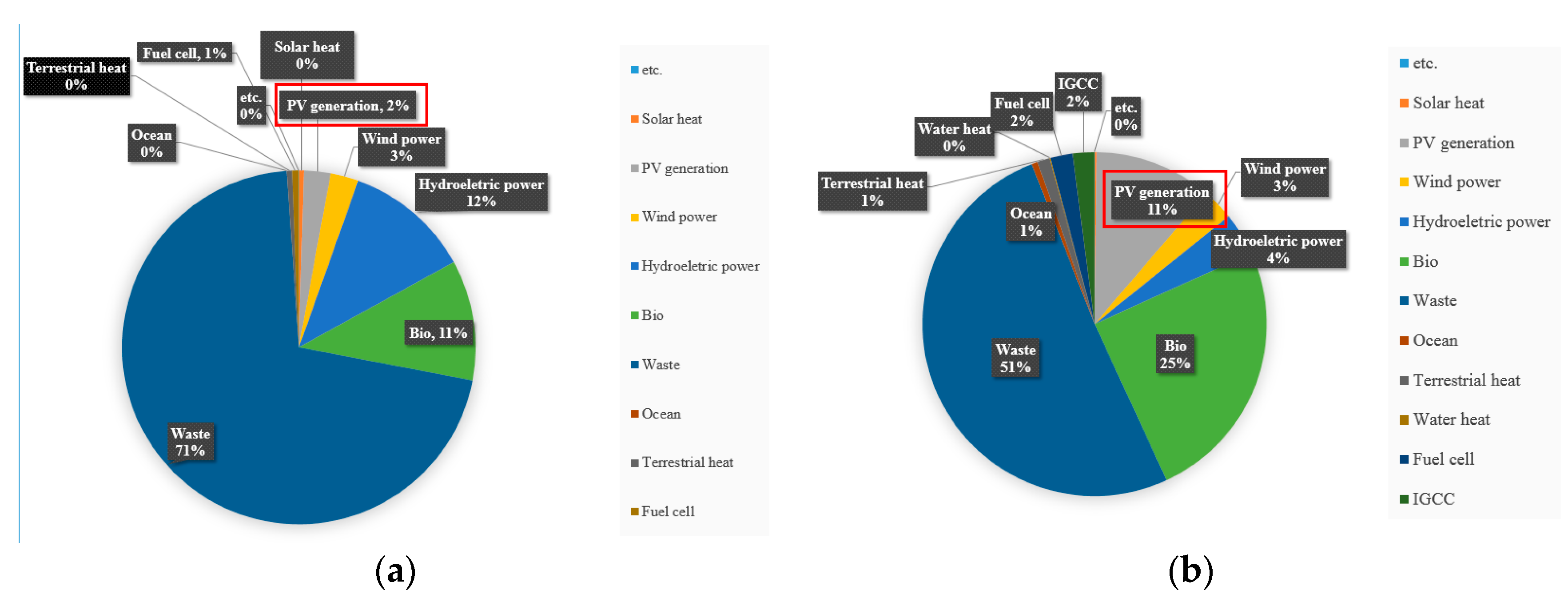
The effects of environmental pollution and climate change due to the massive use of fossil fuels are being felt across the planet. The primary countermeasure to reduce the use of fossil fuels is to improve their efficiency of production, transfer, and consumption. However, it is more important to protect sustainable energy sources by using new renewable energy that does not emit carbon dioxide [1,2]. In addition, power generation using renewable energy is rapidly developing in response to environmental issues and the need to secure sustainable energy. In Korea, photovoltaic generation accounted for 11% of all renewable energy as of 2018, which represents a steady growth when compared with 2% in 2010, as shown in Figure 1 [3].
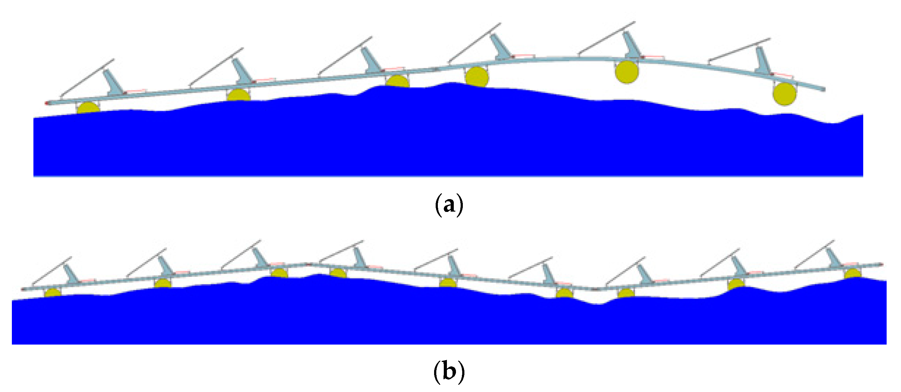
A solar installation site is necessary for constructing a photovoltaic power plant and generating solar power. Therefore, floating photovoltaic power generation has been developed to address issues such as limited availability of space and environmental problems. In floating photovoltaic power plants, the photovoltaic modules are installed on the surface of water. Such plants comprise a floating structure on which the photovoltaic modules are fixed, a buoy that resists the gravitational force of the structure, and a mooring system that fixes the horizontal load. The floating structure should firmly support the photovoltaic modules and provide sufficient resistance to external forces such as wind loads and waves. Moreover, it should secure long-term durability against corrosion, fatigue, etc., because it is located on water, which is a special condition. In the case of a continuous structure, excessive flexural moment load may be exerted on the structural members due to water-surface movement, as depicted in Figure 2a, thereby damaging the structure. Therefore, for structural safety and constructability, the structure must be designed as a unit. In addition, it must be connected with hinges to minimize the transfer of flexural moment so that the structure can sensitively react to water surface movement, as depicted in Figure 2b.
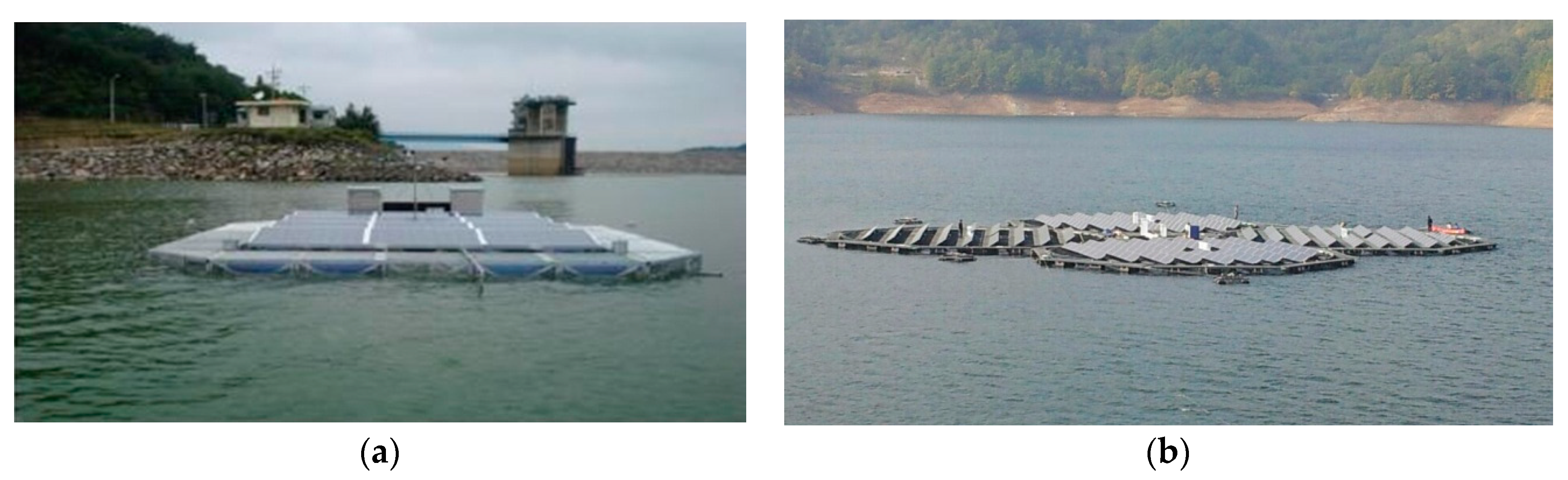
Floating photovoltaic power generation systems gained popularity in 2007, both domestically and internationally. The first commercialized floating photovoltaic power plant was installed by SPG Solar in July 2007 in a reservoir in the Far Niente Farm, Napa Valley, California, USA. This system is presumed to be installed to suppress evaporation from the reservoir [4,5]. In Asia, the first floating photovoltaic power generation system was installed in a reservoir in Aichi, Japan, in August 2007. In this system, the angle of inclination of the installed photovoltaic modules was 10°, which has the same effect as being installed at 30° on land towing to the various effects of the water surface [4,6]. Majid et al. installed 80-W photovoltaic panels on a pond and compared the amount of electricity generated from the installed panels with that of general photovoltaic panels. Their experimental findings confirmed that the floating photovoltaic panels generated 15.5% more power [7]. Dai et al. designed and constructed a 100-kW-class floating photovoltaic power generation system composed of high-density polyethylene (HDPE) in the Teggeh reservoir, Singapore, in 2018 [8]. Santafé et al. developed a floating photovoltaic cover system (FPCS) to reduce evaporation in reservoirs and generate renewable electricity. The FPCS structure, which was configured and implemented over the entire surface, could generate 425,000 kWh/year of renewable energy and simultaneously prevented the evaporation of 5000 m3 of water per year (25% of the reservoir storage capacity) [9]. After examining several design methods for installing a floating platform, Cazzaniga et al. proposed an efficient and economical design method. In particular, they applied tracking and cooling functions to the floating platform, and after analyzing the structure using a flat reflector, confirmed that the cost of generating electricity could be lowered [10]. In Korea, systematic research on floating photovoltaic power generation commenced in 2009. As seen in Figure 3, K-water installed a prototype at the Juam Dam in 2009, and showcased a technology called solar-tracking floating photovoltaic power generation at the Hapcheon Dam in 2013. Choi and Lee [11] verified the stress applied to floating photovoltaic power generation structures by the structural material through finite element analysis, and analyzed the structural behavior of solar-tracking floating photovoltaic power generation structures through wind tunnel and durability tests. Lee et al. designed a floating photovoltaic power generation structure using fiber-reinforced polymer plastic (FRP) and confirmed the structural safety of the designed structure through finite element analysis. In addition, after constructing and installing the designed floating photovoltaic power generation structure, the amount of power generated by the structure on land and water were compared [12]. In 2013, Kim et al. designed and constructed a floating photovoltaic power generation structure using FRP members on the intake channel of a thermal power plant and confirmed the safety of the structure through finite element analysis. In addition, the costs of the structural materials required for structural member changes were comparatively analyzed [13]. By installing a 3.5-MW-class floating photovoltaic power generation structure on a thermal power plant ash pond, Choi et al. compared the amount of power generated between structures installed on the thermal power plant ash pond and on the intake channel; their findings indicated that the structure on the thermal power plant ash pond generated approximately 1.38 times more power than that installed on the intake channel [2]. Jang et al. examined the structural behavior of a solar-tracking floating photovoltaic structure through finite element analysis; their experimental measurement result of the deformation of structural members by surface waves after construction confirmed that the maximum generated stress was within the allowable limit [14]. Ryu and Lee utilized computational fluid dynamics to analyze the effect of the wind direction and angle of inclination on the wind load, and confirmed that the wind load increased with the increase in the angle of inclination of the photovoltaic panel to the ground [15]. Oh and Jang investigated the installation angle of offshore photovoltaic power generation systems. By modeling a photovoltaic panel and simulating the changes in the amount of power generated by the photovoltaic array in accordance with the amount of daily light, they confirmed that when installing a photovoltaic structure on water, a panel installation angle of 20° generated more power than that of 30–36° suggested for land [16].
Floating photovoltaic power generation is similar to terrestrial photovoltaic power generation. However, as the power plant is installed on floating photovoltaic modules, it is necessary to understand the floating structure technology, which is a critical technical variable. In terrestrial photovoltaic power plants, only the load generated by the empty weight and the weather conditions are considered with respect to the load on the photovoltaic module. As the load is also transferred to the ground through the structures, the load transfer structure is not complicated; hence, safety can be secured through a simple structural design alone. However, for floating photovoltaic power generation, the load on the photovoltaic module is a combination of loads generated by the weather conditions and fluid loads generated by surface displacement; the loads are divided into gravitational and horizontal loads, delivered to the buoys and mooring system, respectively. In addition, as the floating structure supporting the photovoltaic modules is mechanically connected and there are multiple photovoltaic module arrays, all the horizontal loads on the power plant are transferred to the mooring system. Therefore, it is difficult to clearly evaluate the load state on the power plant, and structural-behavior prediction becomes inaccurate, necessitating reviews on various aspects.
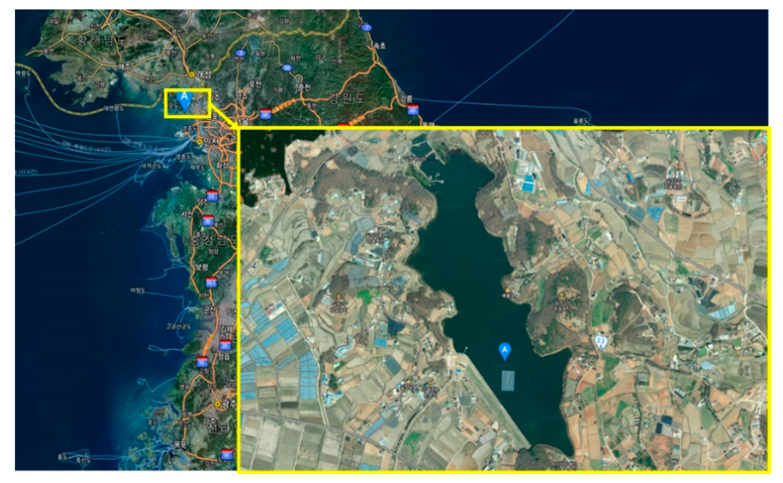
In this study, we verify the structural stability of a floating photovoltaic power generation structure composed of high-durability steel through numerical analysis. Suitable materials were selected by analyzing the economic feasibility of the floating photovoltaic power generation structure with respect to the structural material. To predict the behavior of the structure on water, the behavior of the structural material was verified through finite element analysis. Furthermore, we examined the safety of the structure under wave-height impact through finite element analysis. Based on the obtained results, we fabricate the structure, and constructed and installed a floating photovoltaic power generation structure in a reservoir located in Ganghwa-gun, Incheon, as shown in Figure 4.
2. Economic Feasibility Analysis
We examined the economic feasibility of the floating photovoltaic power generation structures with respect to the structural materials. The material properties of high-durability steel, aluminum, and FRP are summarized in Table 1. Among the building materials used recently for floating photovoltaic power generation structures in Korea, high-durability steel (i.e., PosMac—POSCO magnesium aluminum alloy coating product), aluminum, and FRP were selected and compared by examining the number of unit structural members and buoys required to build a 500-kW-class floating photovoltaic power generation structure, and the material cost. The economic feasibility analysis results indicated that FRP was more expensive than aluminum and high-durability steel was less expensive. As high-durability steel is heavier than FRP and aluminum in terms of the unit material weight, the number of buoys required is higher than in the case of aluminum and FRP. However, the number of high-durability steel unit structural members required to install a 500-kW-class floating photovoltaic power generation structure is less than those of FRP and aluminum. Accordingly, the total cost of the structural system for constructing a 500-kW-class floating photovoltaic power generation plant using high-durability steel members was confirmed to be 38.19 times lower than that of aluminum and 30.27 times lower than that of FRP. Therefore, it was estimated that high-durability steel is the most cost-effective material for building a 500-kW-class floating photovoltaic power plant. Table 2 shows the economic feasibility evaluation results.
3. Design of 500-kW-Class Floating Photovoltaic System
3.1. Photovoltaic Power Generation Structure
3.1.1. Structural Member
Concrete, which is a traditional construction material, is difficult to use for floating structural members in terms of the economic feasibility and constructability due to its empty weight. However, steel can be used as a structural member by processing it into H-, L-, and C-type thin-plate structural members. In this study, a high Zn-Mg-Al ternary high-corrosion-resistant alloy-plated steel sheet was used. This steel sheet was fabricated with different plating layers. Figure 5 shows the composition of the steel sheet. The alloy-plated steel sheet was plated with ternary Zn (94.5%), Mg (3%), and Al (2.5%). Mg in the plated layer promotes the formation of a highly stable and dense corrosion product, Simonkolleite, which is formed and maintained like a film on the surface of the plated layer, preventing corrosion of the iron plate.
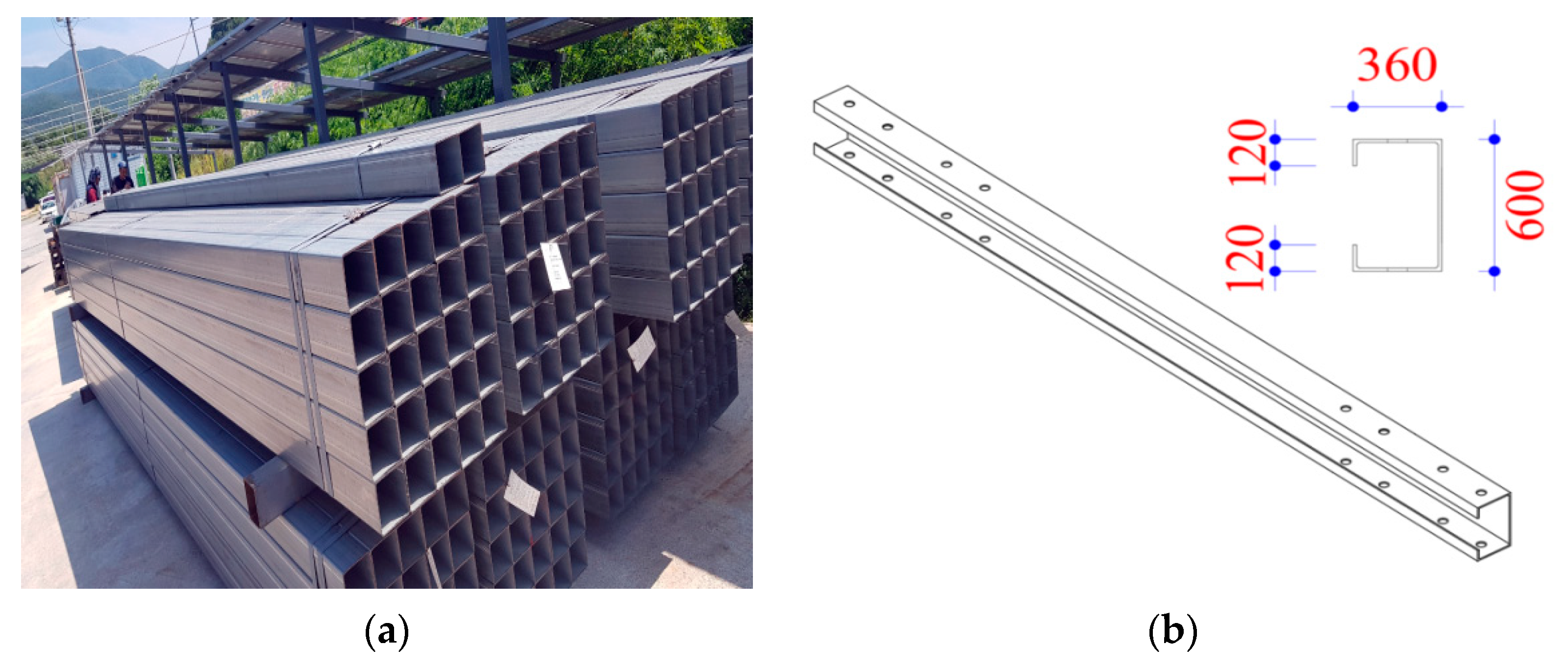
In the event that the surface of the alloy-plated steel is abraded, the upper plating layer is dissolved to cover the cross-section, promoting the growth of a stable corrosion product. The shape of the structural member used in this study is displayed in Figure 6.
3.1.2. Buoy
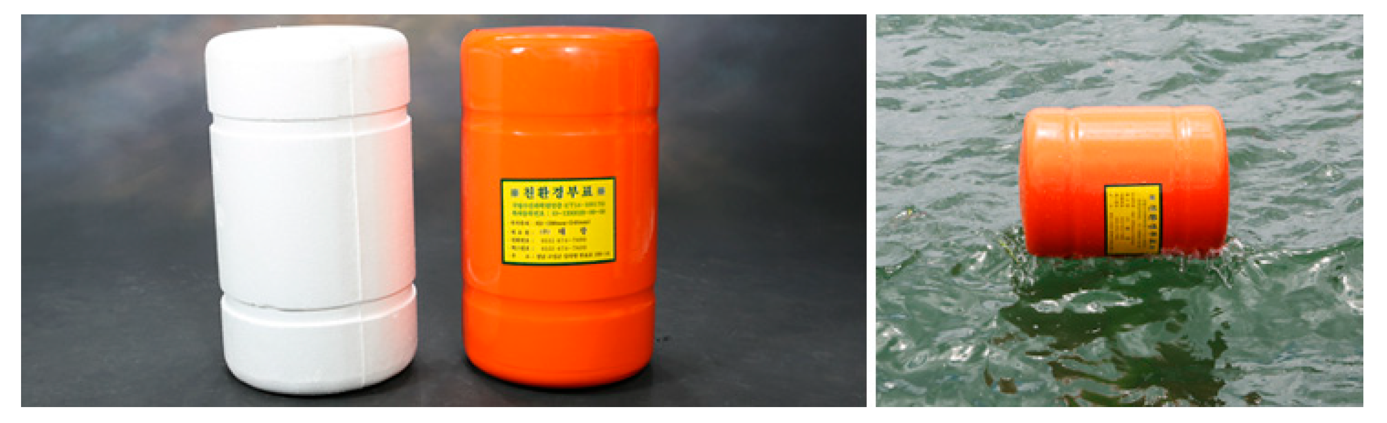
The buoy is a foamed product in which a hydrocarbon gas such as pentane or butane is injected into polystyrene resin, which is expanded with steam; the volume comprises 98% air and 2% expanded polystyrene (EPS), which is resin. EPS is easily breakable as it is fabricated by injecting hydrocarbon gas into polystyrene, which is a type of heat-accelerating plastic. Nevertheless, it is extensively used in domestic fishing and aquaculture due to its high buoyancy, convenience of use, and low cost. The buoy shown in Figure 7 has a diameter of φ 530 and length of 920 mm.
3.2. Unit Module Design
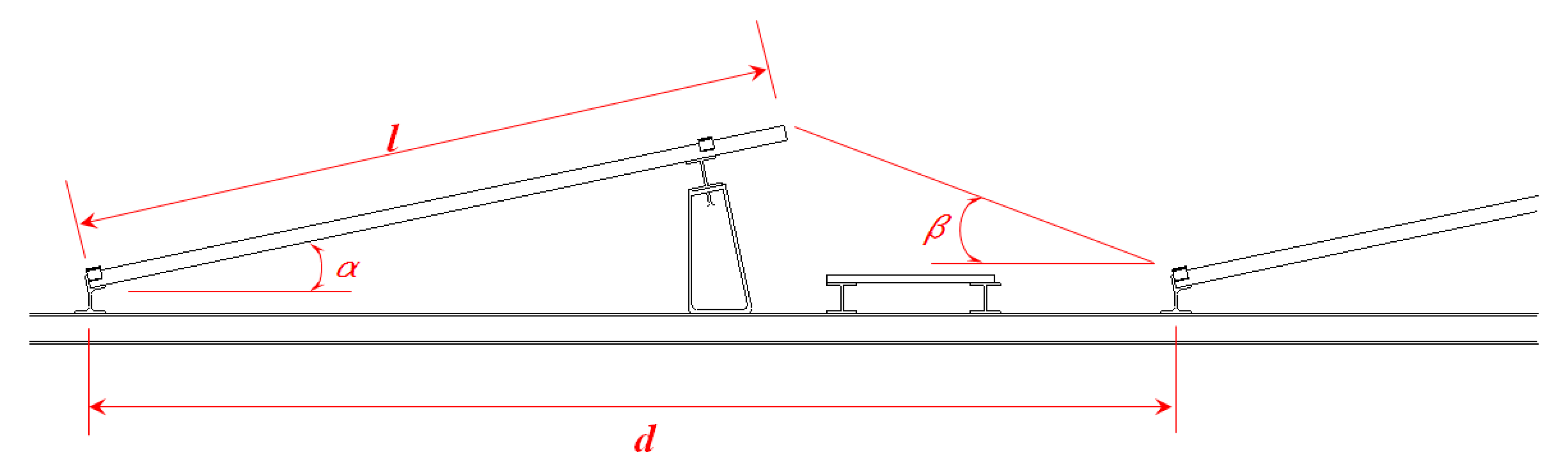
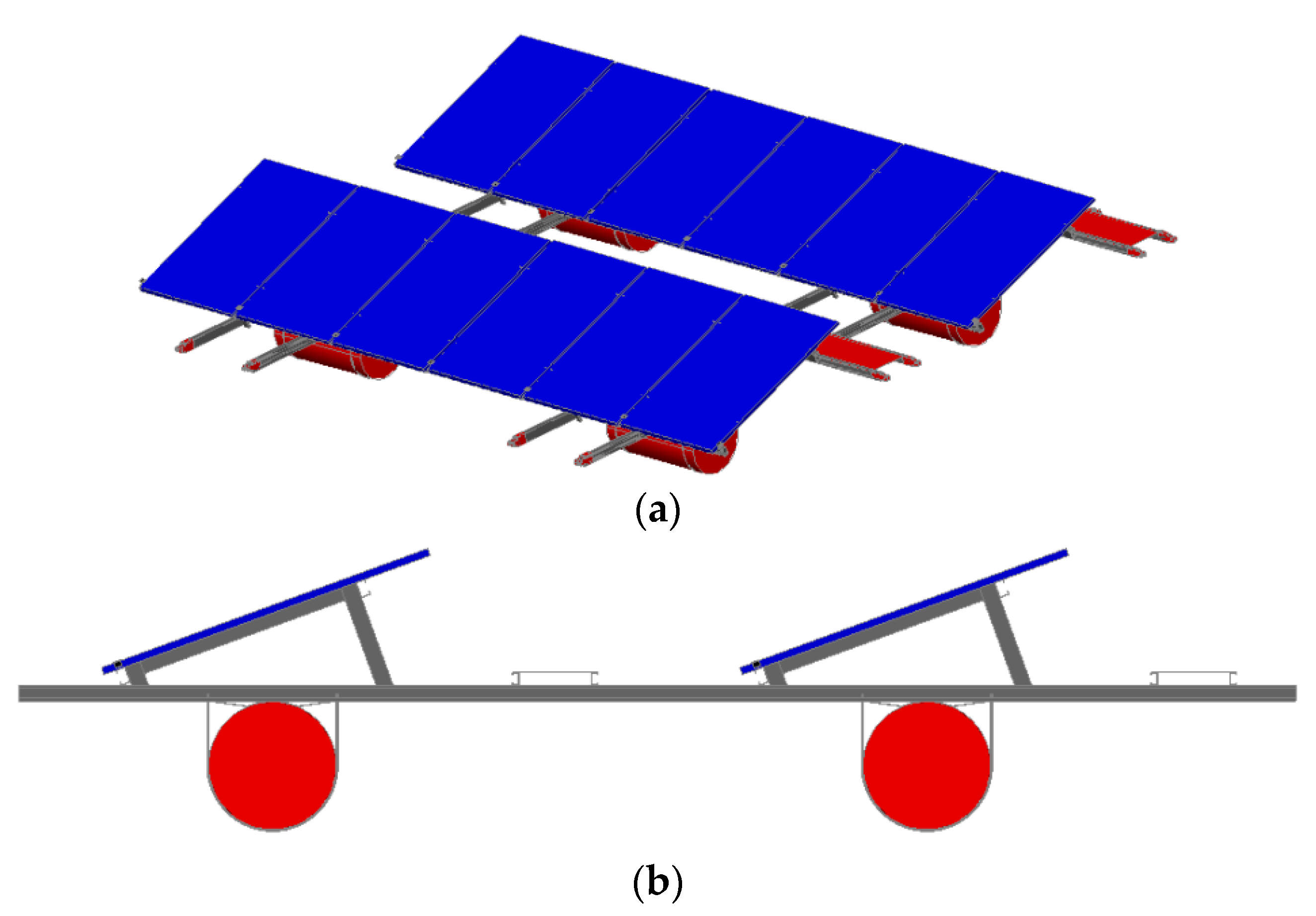
To design a photovoltaic power generation structure, the separation distance of the array was obtained with respect to the installation angle of the photovoltaic module using Equation (1), as shown in Figure 8. For the installation of the photovoltaic module, a 20° angle was applied as suggested by Oh and Jang [16]. We designed a 500-kW-class floating photovoltaic power generation structure with an allowable separation distance of 3000 mm for the array, obtained through Equation (1). The floating photovoltaic power generation unit structure was 6000 in length and 6164 mm in width. The solar module installed in the unit structure had a capacity of 360 W and the number of modules was 12. The photovoltaic power generation unit structure comprises a solar module, structure, and buoy, as shown in Figure 9.
where, : Length of the longer-side of the photovoltaic module (mm); : Installation angle of the photovoltaic module; : Solar azimuth angle; : Allowable separation between the arrays (mm).
3.3. Finite Element Analysis
3.3.1. Modeling
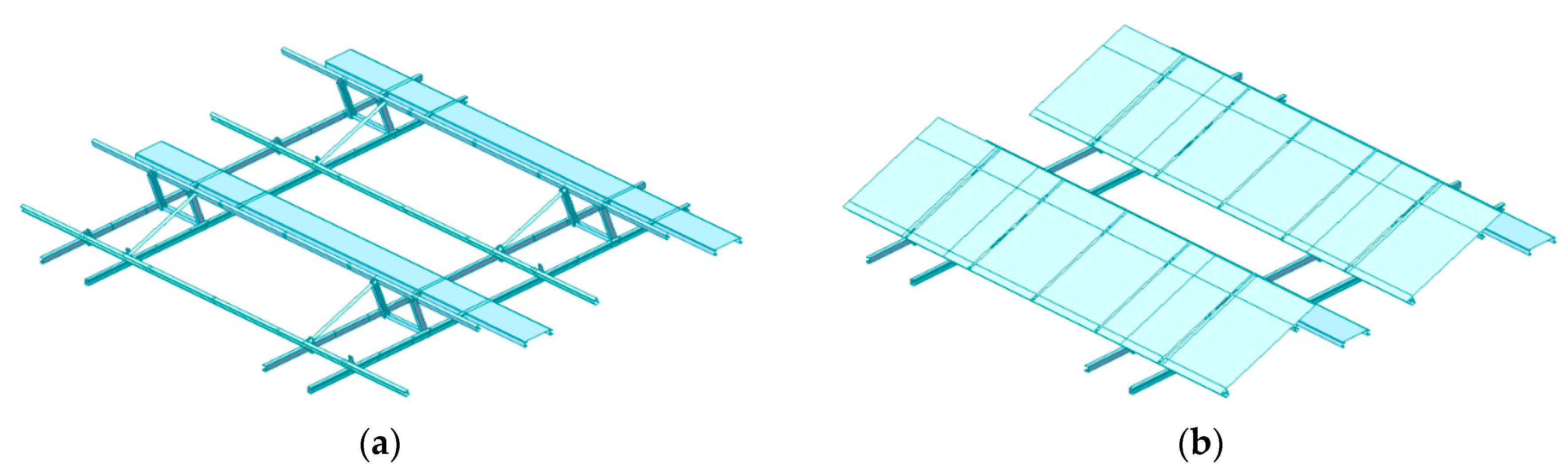
We examined the floating photovoltaic power generation structure using a finite element analysis program to verify the structural safety. For finite element analysis, 3D analysis was performed using MIDAS Civil Ver. 2012, a universal structural analysis program [17]. We applied a 3D frame of PosMac for the structural member (Figure 10a) and a plate element for the photovoltaic modules (Figure 10b). The connecting part was assumed to be connected through hinges. The reaction force according to the displacement using the elastic spring coefficient was applied as the boundary condition.
3.3.2. Load and Boundary Conditions
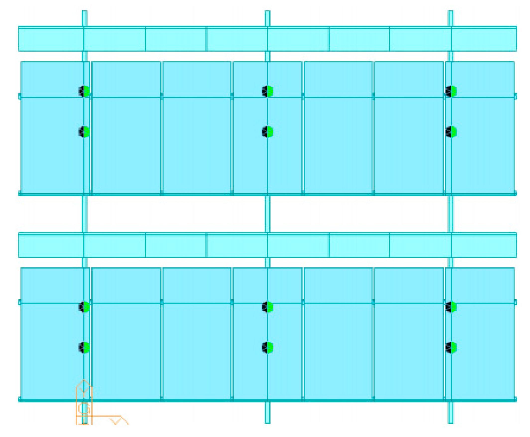
As shown in Figure 11, the boundary conditions applied in the analysis were assumed to be a simple support for the buoy installation position. The combined loads of the empty-weight, wind load, and snow load of the structure were utilized as the load conditions. The structure in Figure 11 includes 304 nodes and 250 elements. For the wind load and snow load applied in the analysis, the design wind velocity and snow load were calculated using Equations (2) and (3), respectively, referring to the Korean Building Code and Commentary (2016) [18]. The wind load and snow load obtained using Equations (2) and (3) were 50.85 m/s and 0.37 kN/m2, respectively.
where V0 is the basic design wind velocity, Kzr is the velocity pressure exposure coefficient, Kzt is the topographic factor, and Iw is the importance factor. Table 3 provides the values of the wind load variables used in the calculation.
where Cb is the roof snow load factor, Ce is the exposure factor, Ct is the temperature coefficient, Is is the importance factor, and Cs is the steepness factor. The snow load variables are given in Table 4.
3.3.3. Finite Element Analysis Results
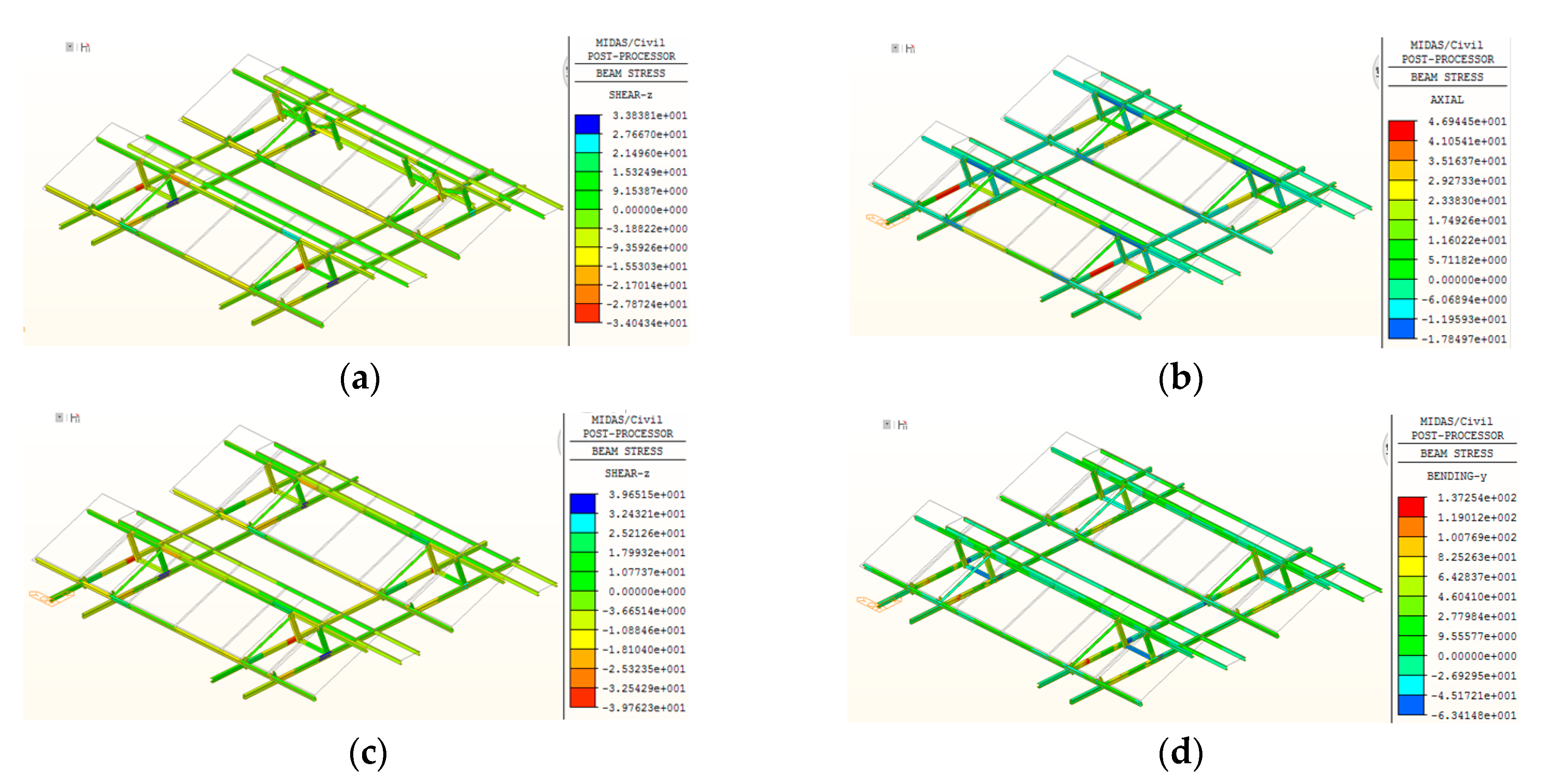
Figure 12 shows the results of the tensile, compressive, shear, and flexural stresses on the structure obtained through finite element analysis; they are summarized in Table 5. It was confirmed that the maximum tensile, compressive, and flexural stresses of the structure obtained through finite element analysis were within the allowable design stress value of 140 MPa suggested by the Korean Building Code and Commentary. The shear stress was also confirmed to be within the suggested allowable design stress value of 80 MPa. Based on the results of finite element analysis, we found that the safety factors of the different stresses ranged from 1.93 to 11.22.
4. Structural Safety Review of Floating Photovoltaic Power Generation Structure
To confirm the safety of the floating photovoltaic power generation structure against wave-height impact, the stress of the structure was verified with respect to the wave height through finite element analysis. For the relationship between the wind velocity, reservoir fetch, and wave height, the Molitor equation presented in the KDS 54.00.00 dam design standard was employed [19]. The design wave height formula proposed by Molitor is represented as Equation (4). Variables under different conditions were applied to this equation.
where : wave height from trough to crest (m); : wind velocity (m/s); : fetch (km), length of the surface on which wind can act (fetch).
4.1. Modeling
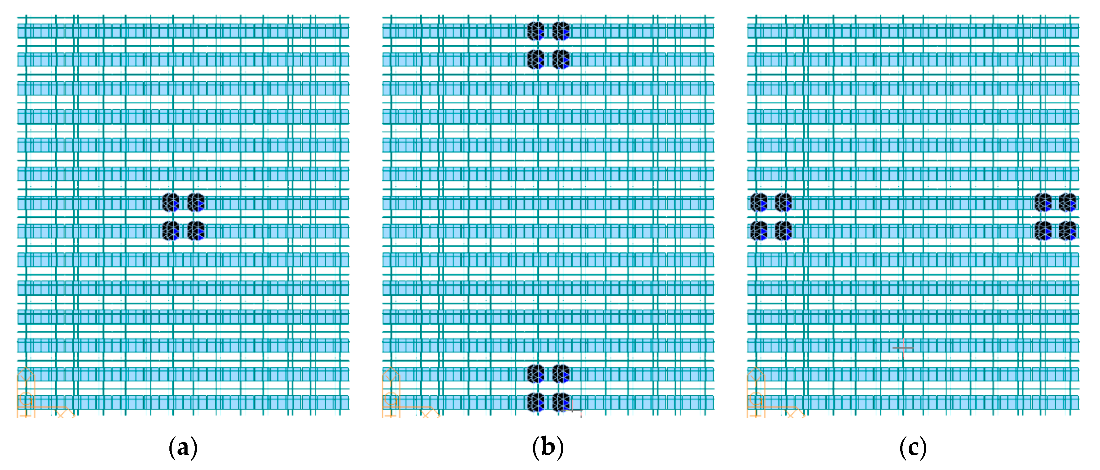
To review the structural safety of the floating photovoltaic power generation structure under wave-height impact, we applied the displacement load by superimposing the stresses generated by external factors such as stresses and wind loads on the structural members due to water-surface movement, and examined the safety of the structure through finite element analysis. The modeling was performed as shown in Figure 13. When the straight distance from the ground to the photovoltaic power generation structure was 0.5 km, the design wind velocity and wave height of Ganghwa Island, where the photovoltaic generation structure was installed, were assumed to be 39.55 m/s and 0.8 m, respectively. The structure in Figure 13 includes 6396 nodes and 4700 elements. For the analysis, the displacement loads were applied in the central part (Figure 13a), front and rear parts (Figure 13b), and side parts (Figure 13c).
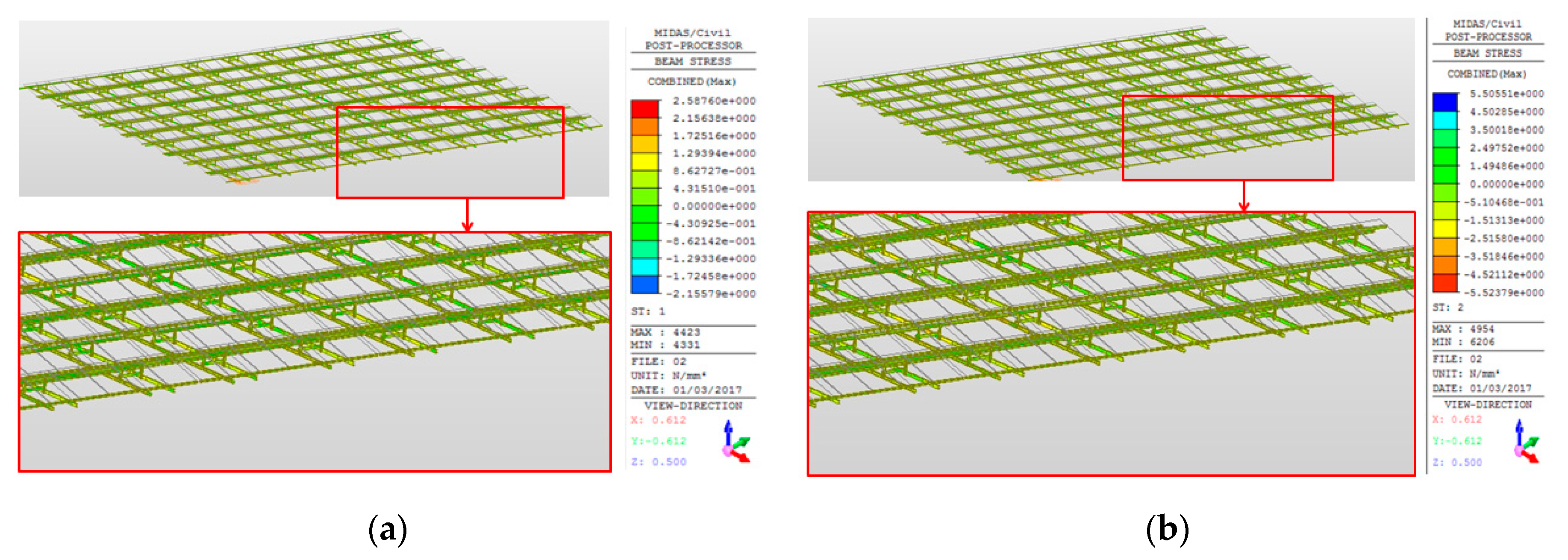
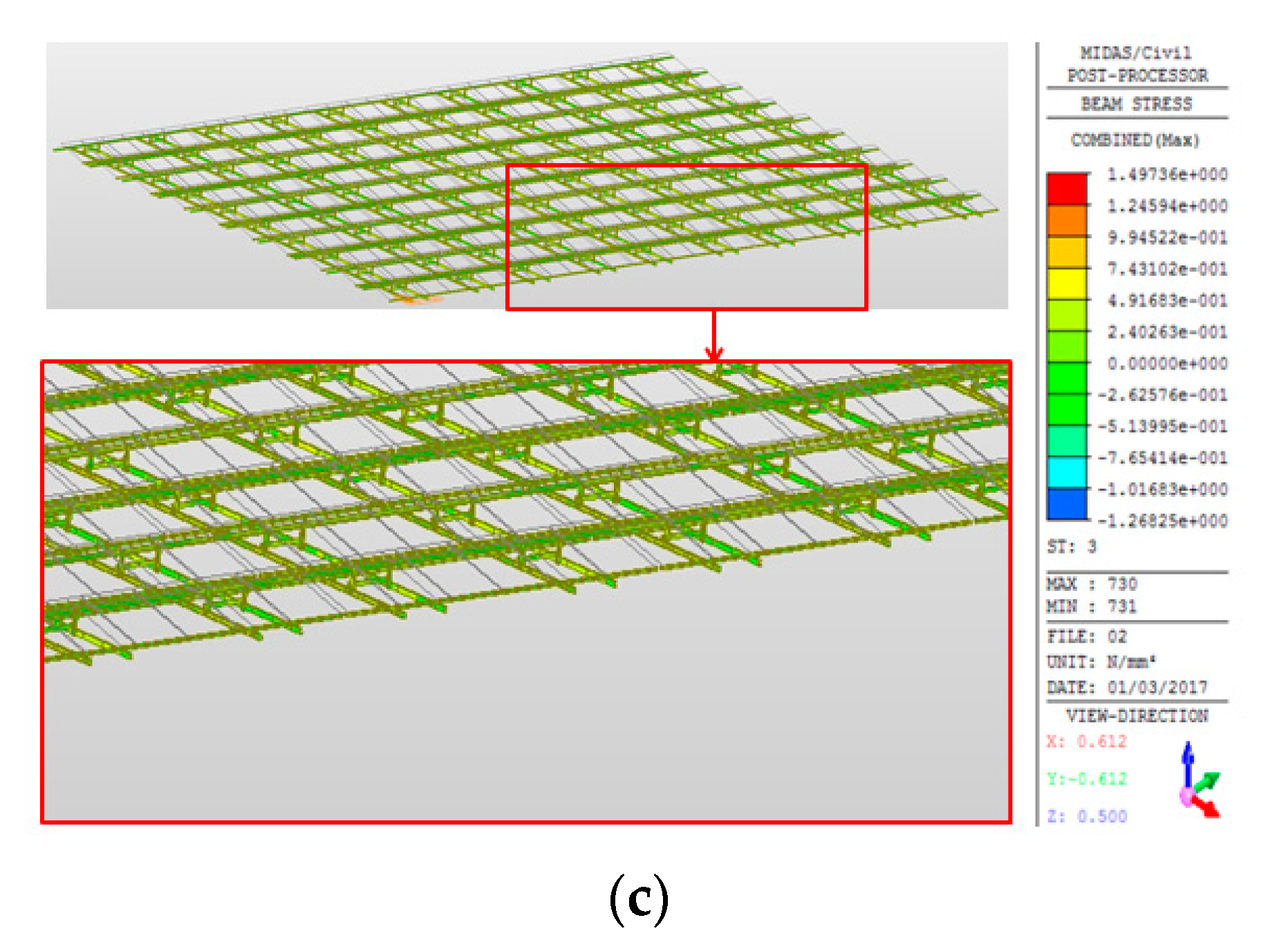
4.2. Finite Element Analysis Results
By applying the displacement load for the design wave height, we examined the safety of the floating photovoltaic power generation structure under wave-height impact through finite element analysis. The review results showed that the stress values were within the allowable design value of 140 MPa suggested by the Korean Building Code and Commentary [18], and confirmed a safety factor of approximately 9% or less for the structure. Figure 14 shows the stress distribution of the structure with respect to the wave height and Table 6 summarizes the finite element analysis results.
5. Construction of the Floating Photovoltaic Generation Structure
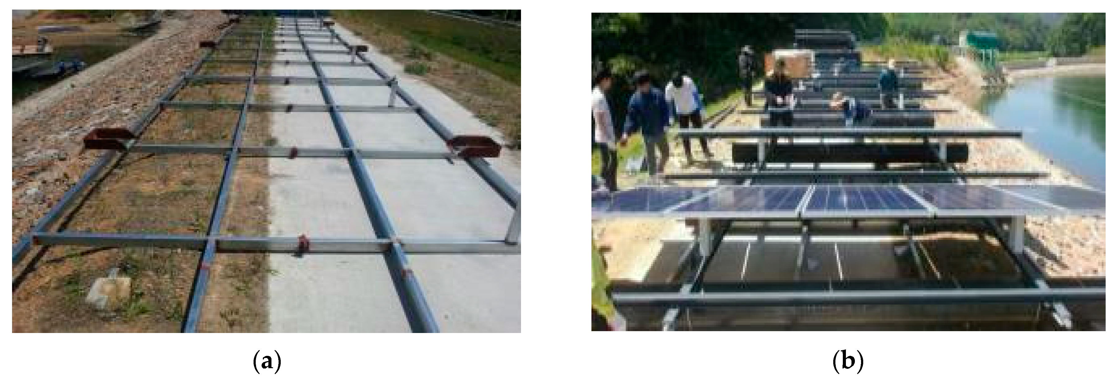
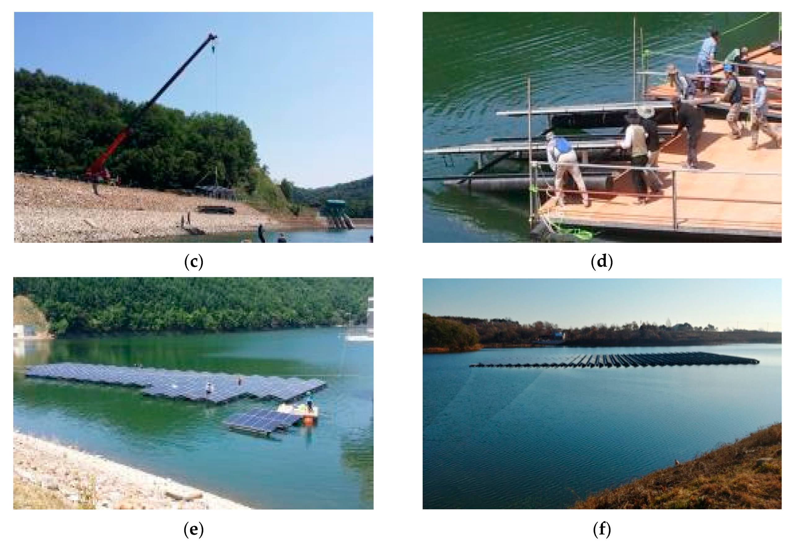
As the floating photovoltaic power generation structure was installed on the surface of water, the work procedure should be simplified considering the site conditions. After the main members were processed and assembled, basic work on the structure for installing the buoys and photovoltaic modules had to be performed on the ground. Subsequently, the structure was floated on water using construction equipment. After the floating structure was lifted and launched, the unit structures were assembled and the driving device was installed. Figure 15 depicts the construction procedure of the 500-kW-class floating power generation structure composed of high-durability steel in the reservoir.
6. Comparison of Terrestrial Photovoltaic and Floating Photovoltaic Generation Systems
The energy generated monthly by the floating photovoltaic generation system is compared with that of the terrestrial photovoltaic generation system. According to the temperature data presented by the Korea Meteorological Administration, the difference between the temperature measured on the water surface and on land near the Incheon-si region is approximately 1.5 °C [2,12]. The measured energy production data of the floating photovoltaic generation system are compared with those of the terrestrial photovoltaic generation system as given in Table 7. As can be seen in Table 7, the energy production of the floating photovoltaic generation system from June to August 2019 was significantly higher than that of the terrestrial photovoltaic generation system. In May, the energy production of the floating photovoltaic generation system was lower than that of the terrestrial photovoltaic generation system owing to wet-fog. Following the comparison, it is found that the energy efficiency of the floating photovoltaic generation system is a maximum of 36.43% higher than that of the terrestrial photovoltaic generation system. Accordingly, it can be said that the floating photovoltaic generation system is effective for energy production.
7. Conclusions
In this study, we reviewed the economic feasibility of floating photovoltaic power generation structures with respect to the structural material, for installation on water. The review results confirmed that high-durability steel was up to 3.5 times more cost effective than the compared materials for constructing and installing a 500-kW-class photovoltaic power generation structure on the surface of water. By reflecting the characteristics of the structure installed on water, cross-section design was performed based on the results of numerical analysis, considering the special conditions on water. Additionally, the finite element analysis performed for the design and structural safety was checked by comparison with the requirements of the Korean Building Code. The design of the member cross-section was completed by comparing the finite element analysis results for the structures with the allowable stress for each structural material used. The results confirmed that the tensile, compressive, flexural, and shear stresses, which are the stresses of the members applied to the structure, were within the allowable domestic design stress values. In addition, the review results of the safety of the structure under wave-height impact, through finite element analysis, indicated that the values were within the allowable domestic design stress values, and a safety factor of approximately 9% or less was confirmed for the structure. Considering the obtained results, 500-kW-class floating photovoltaic power generation structure was constructed in Giljeong Reservoir in Ganghwa Island by applying the design, assembly, and installation process of the floating photovoltaic power generation structure composed of high-corrosion-resistant steel material. Finally, the energy production of the floating photovoltaic generation system was compared with that of the terrestrial photovoltaic generation system, and the energy efficiency of the former was found to be approximately 36.43% higher than that of the latter.
Author Contributions
Conceptualization, S.-H.K. and S.-J.P.; formal analysis, S.-H.K. and S.-C.B.; data curation, S.-C.B. and K.-B.C.; writing—original draft preparation, S.-H.K.; writing—review and editing, S.-H.K. and S.-J.P. All authors have read and agreed to the published version of the manuscript.
Funding
This research received no external funding.
Acknowledgments
This work was supported by Incheon National University (International Cooperative) Research Grant in 2019.
Conflicts of Interest
The authors declare no conflict of interest.
References
- Nam, J.H. Development of Floating Type Photovoltaic Energy Generation System Using the Pultruded Structural Members. Ph.D. Thesis, Hongik University, Seoul, Korea, 28 December 2010. [Google Scholar]
- Choi, J.Y.; Hwang, S.T.; Kim, S.H. Evaluation of a 3.5-MW floating photovoltaic power generation system on a thermal power plant ash pond. Sustainability 2020, 12, 2298. [Google Scholar] [CrossRef] [Green Version]
- Administration Monitoring System. Available online: https://www.index.go.kr/potal/main/EachDtlPageDetail.do?idx_cd=1171 (accessed on 1 September 2020).
- Joo, H.J.; Lee, N.H.; Lee, S.W. Floating photovoltaic power generation system. Korean Soc. Adv. Compos. Struct. 2013, 4, 31–39. [Google Scholar]
- Smyth, M.; Russell, J.; Milanowski, T. Solar Energy in the Winemaking Industry; Green Energy and Technology; Springer: London, UK, 2011. [Google Scholar]
- Trapani, K.; Millar, D.L. Proposing offshore photovoltaic (PV) technology to the energy mix of the maltese islands. Energy Convers. Manag. 2013, 67, 18–26. [Google Scholar] [CrossRef]
- Majid, Z.A.A.; Ruslan, M.H.; Sopian, K.; Othman, M.Y.; Azmi, M.S.M. Study on performance of 80 watt floating photovoltaic panel. J. Mech. Eng. Sci. 2014, 7, 1150–1156. [Google Scholar] [CrossRef]
- Dai, J.; Zhang, C.; Lim, H.V.; Ang, K.K.; Qian, X.; Wong, J.L.H.; Tan, S.T.; Wang, C.L. Design and construction of floating modular photovoltaic system for water reservoirs. Energy 2020, 191, 116549. [Google Scholar] [CrossRef]
- Santafé, M.R.; Soler, J.B.T.; Romero, F.J.S.; Gisbert, P.S.F.; Gozálvez, J.J.F.; Gisbert, C.M.F. Theoritical and experimental analysis of a floating photovoltaic cover for water irrigation reservoirs. Energy 2014, 67, 246–255. [Google Scholar] [CrossRef]
- Cazzaniga, R.; Cicu, M.; Rosa-Clot, M.; Rosa-Clot, P.; Tina, G.M.; Ventura, C. Floating photovoltaic plants: Performance analysis and design solutions. Renew. Sustain. Energy Rev. 2018, 81, 1730–1741. [Google Scholar] [CrossRef]
- Choi, Y.K.; Lee, Y.G. A study on development of rotary structure for tracking-type floating photovoltaic system. Int. J. Precis. Eng. Manuf. 2014, 15, 2453–2460. [Google Scholar] [CrossRef]
- Lee, Y.G.; Joo, H.J.; Yoon, S.J. Design and installation of floating type photovoltaic energy generation system using FRP members. Sol. Energy 2014, 108, 13–27. [Google Scholar] [CrossRef]
- Kim, S.H.; Yoon, S.J.; Choi, W.C. Design and construction of 1 MW class floating PV generation structural system using FRP members. Energies 2017, 10, 1142. [Google Scholar] [CrossRef] [Green Version]
- Jang, M.J.; Kim, S.H.; Lee, Y.G.; Woo, S.B.; Yoon, S.J. Installation and safety evaluation of tracking-type floating PV generation structure. J. Korean Soc. Adv. Compos. Struct. 2014, 5, 1–8. [Google Scholar] [CrossRef]
- Ryu, D.G.; Lee, K.B. Flow characteristics and wind loads on the solar panel and floating system of floating solar generato. J. Korea Acad. Ind. Coop. Soc. 2019, 20, 229–235. [Google Scholar]
- Oh, J.S.; Jang, J.H. A study on the installation angle of the marine solar power generation system. J. Navig. Port Res. 2018, 42, 167–176. [Google Scholar]
- MIDAS Analysis Reference; MIDAS IT: Seoul, Korea, 2012. (In Korean)
- Korean Building Code (KBC); Architectural Institute of Korea: Seoul, Korea, 2016.
- KDS 54 00 00, Dam Design Standard. 2016. Available online: www.kcsc.re.kr (accessed on 30 June 2016).
Figure 1.
Korea renewable energy supply status in 2010 vs. 2018. (a) 2010; (b) 2018.

Figure 2.
Behavior of the floating structure. (a) Continuous structural members; (b) discontinuous structural members.
Figure 2.
Behavior of the floating structure. (a) Continuous structural members; (b) discontinuous structural members.

Figure 3.
Floating photovoltaic power generation structure. (a) Structure in Juam Dam; (b) structure in Hapcheon Dam.
Figure 3.
Floating photovoltaic power generation structure. (a) Structure in Juam Dam; (b) structure in Hapcheon Dam.

Figure 4.
Location of the photovoltaic power generation structure.

Figure 5.
Composition of alloy plated steel sheet.

Figure 6.
Alloy-plated steel sheet member. (a) Shape of alloy plated steel sheet members; (b) dimensions of alloy plated steel sheet cross-section (mm).
Figure 6.
Alloy-plated steel sheet member. (a) Shape of alloy plated steel sheet members; (b) dimensions of alloy plated steel sheet cross-section (mm).

Figure 7.
High-density expanded polystyrene (EPS).

Figure 8.
Separation distance.

Figure 9.
Floating photovoltaic system. (a) Unit module; (b) side view.

Figure 10.
Modeling. (a) Frame; (b) photovoltaic module.

Figure 11.
Boundary conditions.

Figure 12.
FEA results. (a) Tensile stress; (b) compressive stress; (c) shear stress; (d) flexural stress.
Figure 12.
FEA results. (a) Tensile stress; (b) compressive stress; (c) shear stress; (d) flexural stress.

Figure 13.
Finite element analysis (review of wave-height impact). (a) Case 1; (b) case 2; (c) case 3.
Figure 13.
Finite element analysis (review of wave-height impact). (a) Case 1; (b) case 2; (c) case 3.

Figure 14.
Stress distribution of the structure according to wave height. (a) Case 1; (b) case 2; (c) case 3.
Figure 14.
Stress distribution of the structure according to wave height. (a) Case 1; (b) case 2; (c) case 3.


Figure 15.
Construction procedure of the floating photovoltaic power generation structure. (a) Basic frame assembly; (b) photovoltaic module installation; (c) lifting; (d) launching; (e) assembly on water surface; (f) completion.
Figure 15.
Construction procedure of the floating photovoltaic power generation structure. (a) Basic frame assembly; (b) photovoltaic module installation; (c) lifting; (d) launching; (e) assembly on water surface; (f) completion.


Table 1.
Mechanical properties of materials.
| Description | Young’s Modulus (, ) | Tensile Strength (, ) | Shear Strength (, ) | Unit Weight (, ) |
|---|---|---|---|---|
| High-durability steel | 205.00 | 235.00 | 135.00 | 77.00 |
| Aluminum | 69.60 | 103.03 | 61.82 | 26.49 |
| FRP | 33.28 | 201.29 | 26.40 | 18.42 |
Table 2.
Review of the economic feasibility of a floating photovoltaic power generation structure with respect to the structural material.
Table 2.
Review of the economic feasibility of a floating photovoltaic power generation structure with respect to the structural material.
| Classification | High-Durability Steel | Aluminum | FRP |
|---|---|---|---|
| Unit cost of structural member ($) | 313 | 583 | 600 |
| Number of units | 161 | 161 | 161 |
| Structure weight (kN) | 2.628 | 1.716 | 1.569 |
| Cost of the structural members ($) | 53,935 | 117,396 | 107,333 |
| Buoy (PE + lightweight filler) (L) | 536 | 350 | 320 |
| Total buoys (L) | 86,296 | 56,350 | 51,520 |
| Cost of the buoys ($) | 21,574 | 14,088 | 12,880 |
| Other expenses | 29,167 | 27,500 | 27,500 |
| Construction cost (structure + mooring) | 37,500 | 37,500 | 37,500 |
| Total cost ($) | 142,176 | 196,483 | 185,213 |
Table 3.
Wind load variables.
| Description | ||||
|---|---|---|---|---|
| Value | 45 | 1.13 | 1.0 | 1.0 |
Table 4.
Snow load variables.
| Description | ||||||
|---|---|---|---|---|---|---|
| Value | 0.5 | 0.7 | 0.8 | 1.2 | 1.2 | 0.91 |
Table 5.
Finite element analysis results.
| Classification | Maximum Stress Obtained Through Finite Element Analysis (MPa) (1) | Allowable Design Stress (MPa) (2) | Safety Factor (2)/(1) |
|---|---|---|---|
| Tensile stress | 12.48 | 140 | 11.22 |
| Compressive stress | 18.87 | 140 | 7.42 |
| Shear stress | 28.63 | 80 | 2.79 |
| Flexural stress | 72.56 | 140 | 1.93 |
Table 6.
Results of finite element analysis considering wave height.
| Classification | Stress | Stress for Wave Height Analysis (MPa) | Stress FEA (MPa) (1) | Allowable Stress (MPa) (2) | Safety Factor (2)/(1) |
|---|---|---|---|---|---|
| Case 1 | Tensile | 2.59 | 129.16 | 140 | 1.083 |
| Compressive | 2.16 | 128.73 | 1.087 | ||
| Case 2 | Tensile | 5.51 | 132.08 | 1.059 | |
| Compressive | 5.52 | 132.09 | 1.059 | ||
| Case 3 | Tensile | 1.50 | 128.07 | 1.093 | |
| Compressive | 1.27 | 127.84 | 1.095 |
Table 7.
Comparison of monthly energy production efficiencies.
| Month | Type of Photovoltaic Generation (kW) | 100 (%) | |
|---|---|---|---|
| Terrestrial ① | Floating ② | ||
| January | 46,294 | 52,589 | 11.97 |
| February | 45,854 | 57,039 | 19.60 |
| March | 59,660 | 68,075 | 12.36 |
| April | 53,580 | 69,230 | 22.60 |
| May | 66,937 | 52,589 | −27.28 |
| June | 58,650 | 64,172 | 8.60 |
| July | 48,256 | 75,916 | 36.43 |
| August | 55,886 | 74,233 | 24.71 |
| September | - | 43,968 | - |
| October | - | 60,081 | - |
| November | - | 28,041 | - |
| December | - | 40,264 | - |
© 2020 by the authors. Licensee MDPI, Basel, Switzerland. This article is an open access article distributed under the terms and conditions of the Creative Commons Attribution (CC BY) license (http://creativecommons.org/licenses/by/4.0/).
Share and Cite
MDPI and ACS Style
Kim, S.-H.; Baek, S.-C.; Choi, K.-B.; Park, S.-J. Design and Installation of 500-kW Floating Photovoltaic Structures Using High-Durability Steel. Energies 2020, 13, 4996. https://0-doi-org.brum.beds.ac.uk/10.3390/en13194996
AMA Style
Kim S-H, Baek S-C, Choi K-B, Park S-J. Design and Installation of 500-kW Floating Photovoltaic Structures Using High-Durability Steel. Energies. 2020; 13(19):4996. https://0-doi-org.brum.beds.ac.uk/10.3390/en13194996
Chicago/Turabian StyleKim, Sun-Hee, Seung-Cheol Baek, Ki-Bong Choi, and Sung-Jin Park. 2020. "Design and Installation of 500-kW Floating Photovoltaic Structures Using High-Durability Steel" Energies 13, no. 19: 4996. https://0-doi-org.brum.beds.ac.uk/10.3390/en13194996
Note that from the first issue of 2016, this journal uses article numbers instead of page numbers. See further details here.