Maximum Power Point Tracking and Voltage Regulation of Two-Stage Grid-Tied PV System Based on Model Predictive Control


1
School of Control and Computer Engineering, North China Electric Power University, Beijing 102206, China
2
State Key Laboratory of Alternate Electrical Power System with Renewable Energy Sources, North China Electric Power University, Beijing 102206, China
3
Department of Electrical and Computer Engineering, Baylor University, Waco, TX 76798, USA
*
Author to whom correspondence should be addressed.
Energies 2020, 13(6), 1304; https://0-doi-org.brum.beds.ac.uk/10.3390/en13061304
Submission received: 3 February 2020
/
Revised: 27 February 2020
/
Accepted: 8 March 2020
/
Published: 11 March 2020
(This article belongs to the Special Issue Photovoltaic Systems: Modelling, Control, Design and Applications)
Abstract
:This paper proposes a maximum power point tracking (MPPT) and voltage regulation method based on model predictive control (MPC) for the two-stage grid-tied photovoltaic (PV) system, which can achieve MPPT and output voltage regulation of a PV system simultaneously. The MPPT algorithm based on MPC is implemented in a DC-DC boost converter. The reference voltage at maximum power point is obtained by dual step Incremental Conductance (I&C) algorithm under the rapidly varying illumination intensity, and the MPPT controller only needs to minimize one cost function of PV current, without pulse width modulation (PWM) module. To inject the generated PV power into the grid with high quality, this paper designs voltage regulation controller based on MPC to maintain the output voltage of the PV system at the desired value. The MPC controller outputs the optimal duty signal with the input and state constraints in the inner loop, and the PI controller in the outer loop is designed to improve the dynamic performance. The proposed method based on MPC was demonstrated using the SimPower systems tool in MATLAB/Simulink. Analysis and simulation results for the PV system show possible improvements on the closed-loop performance such as fast response and low overshoot.
1. Introduction
With the development of renewable energy sources, solar energy, as a widespread and clean energy, has attracted the scientific and industrial interest in recent years. The applications of the distributed photovoltaic system and DC microgrid increase the utilization of solar energy. Meanwhile, the rise of the power electronic technology (e.g., DC-DC conversion) further extends the research boundaries of the photovoltaic system and improves the efficiency of energy conversion [1,2]. However, the rapid change of environmental conditions still has a harmful effect on efficiency and stabilization of PV system. In addition, to inject the generated PV power into the grid with high quality, the output voltage of the PV system also needs to be regulated. Hence, for the PV system, it is necessary to solve the maximum power point tracking and output voltage regulation issues. Many studies have researched the MPPT control issue of the PV system in recent years [3,4,5,6,7,8,9,10,11,12]. The MPPT methods for the PV system are summarized and compared in [13]. As the traditional MPPT technology, Perturbation and Observation (P&O) and Incremental Conductance (I&C) are the most extensively used in PV MPPT system [14], which can combine Grey Wolf Optimization (GWO) [15] or Particle Swarm Optimization (PSO) [16], but an obvious oscillation can appear at maximum power point (MPP). The fuzzy logic control (FLC) method without precise model is presented in [17] and genetic algorithm (GA) based FLC is used in [18] to achieve the optimum control. However, the drawback of fuzzy-based MPPT algorithms is that the tracking point is located away from the MPP when the weather conditions change [19]. Recently, the model predictive control has been used for MPPT of the PV system. The MPC-MPPT algorithm is considered in one-step horizon to enhance tracking performance [20,21,22,23]. Furthermore, the number of the required sensors for the MPC controller is minimized. In [24], the MPC-based MPPT is designed for PV system with pulse width modulation (PWM) module, which increases the complexity of DC-DC converter. By estimating the equivalent voltage and resistance of the PV module, the predicted PV power is calculated for ON or OFF state. However, the above MPC-based MPPT need to predict the instantaneous value in ON or OFF state, rather than the average value in the whole switch cycle via one cost function, which can cause prediction errors if sampling time is not short enough.
For the voltage regulation technology, the related control method is often studied, such as the Proportional-Integral-Differentive (PID) control [25], fuzzy logic control [26], feedback linearization control [27], and sliding mode control [28,29,30]. The MPC method is an attractive alternative to control the output voltage of DC-DC converter in power systems. Wei et al. [31] presented the DC-MPC scheme for cascaded modular DC–DC converter. The PI controller is employed for load voltage regulation and the MPC controller is used for duty cycles prediction. However, it does not consider the current and duty cycle constraints of each module. The Generalized Proportional Integral (GPI) observer-based discrete MPC is designed in [32] to predict a lumped time-varying disturbances, and the MPC controller therein regulates the output voltage even the control input gain is not known precisely. The pre-compensated MPC scheme is proposed in [33,34], which can steer a reference voltage value to the primal controller dynamically, without modifying the primal control structure. However, it has to run at slower frequency than the primal controller to meet computational constraints, which limits the ability of the MPC controller.
To inject the generated PV power into the grid with high quality and improve the efficiency of the PV system, it is crucial to achieve MPPT of the PV system together with voltage regulation. Unfortunately, as mentioned above, most studies focus on only one aspect, either MPPT or voltage regulation, instead of dealing with both simultaneously [35]. Besides, no matter what kind of single control structure is adopted, the PV cell cannot achieve the voltage regulation when the PV system operates in MPPT mode [36]. Therefore, the two-stage converter topology structure is considered for the PV system control in this paper. The first converter matches the output and load impedance and tracks the maximum power point, and the second converter regulates the output voltage to the desired value. This paper proposes the MPPT and cascade voltage regulation control strategy based on MPC for the two-stage type PV system, which can achieve MPPT and output voltage regulation of PV system simultaneously. The main contribution can be summarized as follows:
- •
- The MPPT method based on MPC is proposed to track the maximum power point of PV cell module via DC-DC boost converter. The reference voltage at maximum power point is obtained by dual step I&C algorithm under the rapidly varying illumination intensity, and the MPPT controller only needs to minimize one cost function of PV current, without PWM module.
- •
- The voltage control method based on MPC is applied to the DC-DC buck converter to improve the response speed and reduce the overshoot for output voltage regulation. The MPC controller outputs the optimal duty signal with the input and state constraints in inner loop, and the PI controller in outer loop is designed to improve the dynamic performance of DC-DC buck converter.
The rest of this paper is organized as follows. Section 2 describes the PV system model including the PV cell and the DC-DC converter. The MPPT control method and the voltage regulation method based on MPC are presented in Section 3 and Section 4, respectively. Then, simulation results are given using SimPower systems tool in Section 5, and the conclusions are drawn in Section 6.
2. Modeling of Photovoltaic System
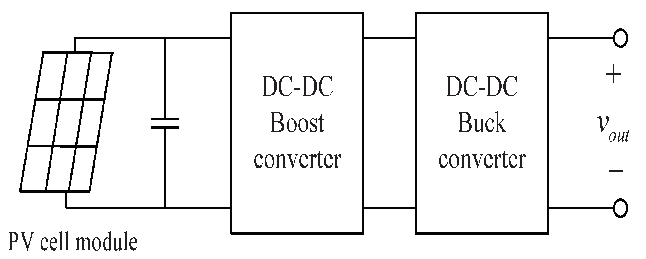
The PV system is divided into two essential parts: the PV cell module and the conversion circuit. The proposed PV system in this paper uses a two-stage topology structure, as shown in Figure 1. The first DC-DC boost converter matches the output impedance of PV cell module with the load impedance and tracks the maximum power point. Then, the stable output voltage can be obtained by the second DC-DC buck converter to supply electricity for the load.
2.1. Photovoltaic Cell
PV cell is the smallest unit of the photo-electricity conversion process. The equivalent circuit of PV cell can be seen as an ideal current source and a diode in parallel. The series and parallel resistance of PV cell internal losses are denoted as and and the output current of PV cell is described as
where is the output voltage of PV cell; and are the light-generated current and the reverse saturation current of diode; and p, q, K, and are constants and represent the diode characteristic factor, electronic charge, Boltzmann’s constant and junction temperature of PV cell, respectively.
Ignoring the impact of series and parallel resistance for PV cell, the short-circuit current of PV cell approximately equals to the light-generated current , and Equation (1) can be rewritten as [37]
where is the open-circuit voltage of the PV cell. Considering the following two conditions: , at the maximum power point and , at open-circuit state, the coefficients and can be obtained as
Under the different illumination intensity and temperature, , , , and will change in a certain range. By introducing the compensation factors a, b, and c, corresponding parameters can be obtained by [38]
where e is natural constant; represents the deviation between the current illumination intensity S and the reference illumination intensity ; represents the deviation between the current temperature T and temperature reference ; and , , , and are the short-circuit current, open-circuit voltage, maximum current, and maximum voltage at reference environmental conditions ( W/m and = 25 C), respectively. According to many data fittings of PV cell, the compensation factor a, b, and c are obtained as follows [38]
2.2. DC-DC Converter
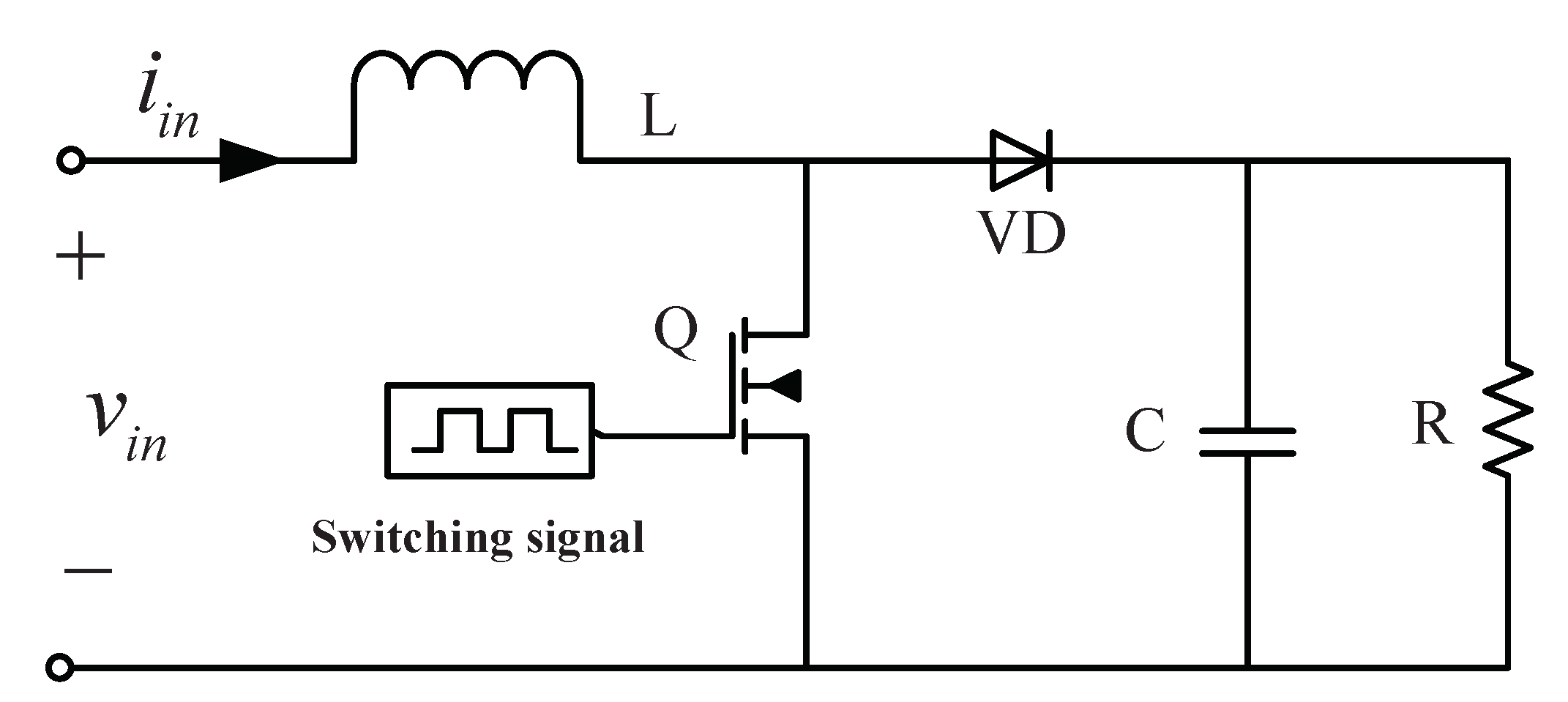
The DC-DC converter is used to achieve the MPPT and output voltage regulation of the PV cells. The boost converter is chosen as an example in this section, which can switch the two operation states (ON and OFF) under high frequency. The circuit topology of the DC-DC boost converter is shown in Figure 2.
Assuming the inductor current is continuous, the parasitic parameters of components are ignored. The inductor current and capacitor voltage are chosen as state vector . When the switch is ON and the switch is OFF, the state equations are, respectively, described as
in which
where is the on-resistance of the switch, R is the load resistance, is the input voltage of boost converter, and is the forward voltage of the diode.
In terms of the average state-space method, the DC-DC boost converter could be modeled by the following state function [39]
where d represents the duty ratio and . Denoting the input signal , Equation (4) can be rewritten as
in which
Using the forward discrete transformation, Equation (5) can be described as
where
and is a sampling time. Similarly, the DC-DC buck converter model can be obtained by the above procedure.
3. MPPT Control Based on MPC Method
In this section, the MPPT controller based on MPC is designed to control the electronic switch without the PWM module. The MPPT principle is that controller switches the operation states (ON or OFF) of DC-DC boost converter by different switching signals u (1 or 0). Hence, the output power will be matched with the load power of the boost converter, and the MPPT will be achieved.
For the PV cell, it is clear that the derivative of output power to the output voltage is equal to zero at the maximum power point
in which
Therefore, by the classical Incremental Conductance (I&C) algorithm [14], one has
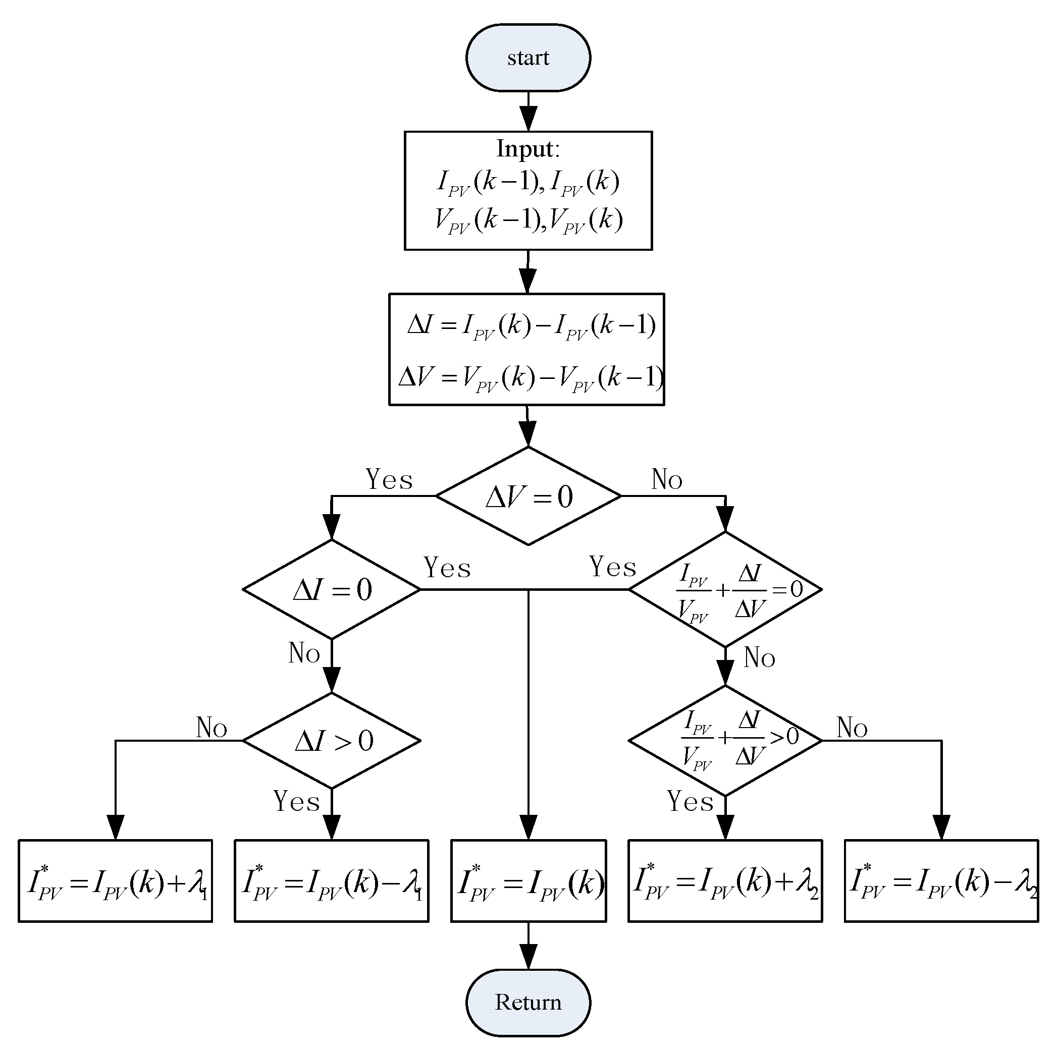
Then, by taking the appropriate step size at current time k, the output current reference of the PV cell at next time can be obtained. The proposed dual step I&C method to determine reference current is shown by the flowchart in Figure 3, in which and represent the different step sizes, and they are set to be and to reduce oscillation.
To satisfy the high-frequency switching action, one-step horizon for MPC is chosen. Define the output current of PV cell , the prediction model can be derived by Equation (6) as follow
The control objective of MPPT is that the output current of the PV cell tracks the reference value. Hence, the cost function can be written as
For the MPPT of PV system, the MPC optimization problem can be written as
| subject to (7). |
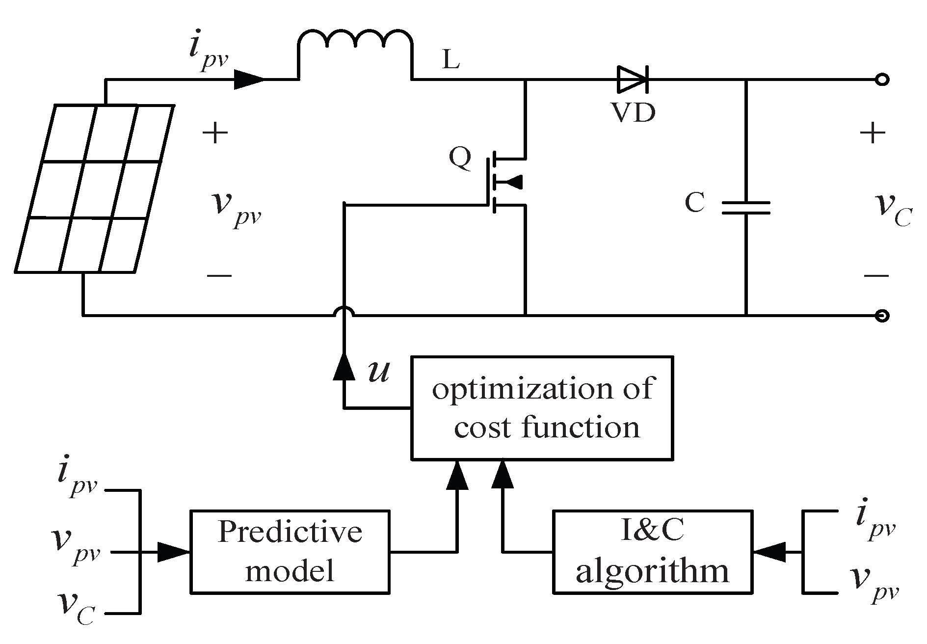
Then, the switch state will be determined by solving the above optimization problem, and the control system structure of DC-DC boost converter is illustrated in Figure 4.
4. Voltage Regulation Based on MPC Method
In this section, the control scheme for the output voltage regulation of the PV system based on MPC is proposed. First, the MPC controller in the inner loop is designed to satisfy the high-frequency switching action. Meanwhile, we select the short sampling time and control horizon by trial and error such that the closed system can achieve better performance while online computational burden is not too heavy. Then, the PI controller in the outer loop is designed to improve the dynamic response performance of the DC-DC buck converter.
4.1. Inner Loop MPC Design
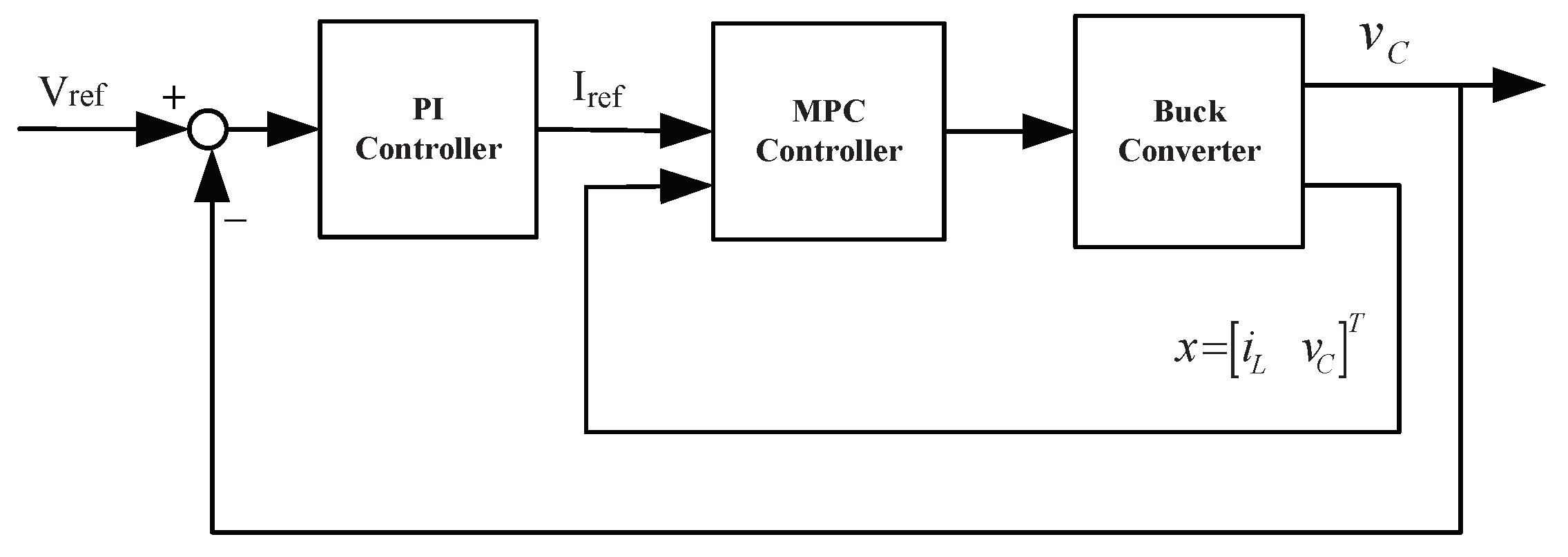
According to the average current control method, the MPC objective is that the inductor current can always be maintained at reference current , while the input constraints are satisfied. The total block diagram for voltage regulation with buck converter is shown in Figure 5.
The MPC controller consists of two parts: predictive model and optimization of cost function. The predictive model can be obtained from Equation (6)
where represents the prediction for time at current time k.
Define as the state variable at steady-state and as the steady-state input. The numerical equation is expressed as follow:
where . By replacing with , the and at time k can be obtained from Equation (10)
in which
where represents the element of the mth row and nth column in matrix A, represents the mth element of column vector F, and so on.
Considering the closed-loop characteristic, the following cost function with quadratic performance index is designed, which includes the state and input .
where P and Q are positive definite symmetric weighting matrices and is the predictive and control horizon.
Considering input and state constraints, the duty ratio of the buck converter will be chosen in , and the inductor current should not be too large. Hence, the variables will also be bounded as follows
Therefore, the MPC optimization problem can be formulated as
| subject to Equations (9) and (13). |
Obviously, the optimization problem is a simple programming problem about . Hence, the optimal solution of cost function in Equation (12) can be obtained using Matlab Optimization Toolbox, and the solving process will be omitted because of limited space.
According to MPC theory, the first element of the optimal solution is applied to the boost converter, the control input of current time can be expressed as
4.2. Outer Loop PI Design
This subsection introduces an outer loop PI voltage controller, which can compensate for the offset of MPC and quicken the dynamic response of the buck converter. The control output of the outer loop is the MPC reference current for the inner loop. The control objective is to track the reference voltage signal
Therefore, the PI control law can be written as follow:
Meanwhile, we have
By defining the capacitor voltage error as and combining Equations (14)–(16), the steady-state error equation can be obtained as follows:
where
All the poles of the characteristic in Equation (17) are within the unit circle after z-transformation in order to ensure the stability of the system. According to Routh’s stability criterion, the value range of and can be given as
5. Simulation Results
The proposed MPPT and voltage regulation control methods based on MPC for the PV system were applied using SimPower systems tool in MATLAB/Simulink, which provides component libraries and analysis tools to investigate system-level performance for the electrical power system. The parameters of DC-DC boost and buck converter were designed by Ang and Oliva [39] and the quantitative comparison was to evaluate the control performance of different control methods.
Remark 1.
The sampling time was chosen as 10 μs, which corresponds to a sampling frequency of 100 kHz. To get good performance controller, the sampling frequency should be much higher than the switching frequency, such as 10–20 times higher according to the guidelines for accurate modeling of power electronics [40]. In this simulation, the switching frequency was 10 kHz, which results in the sampling frequency of 100∼200 kHz, i.e., the sampling time of 5∼10 μs. In addition, this sampling time was also chosen based on the capability of the dSPACE DS1007 platform processor, which we plan to use for expedited prototyping in the future. The control algorithm was implemented in MATLAB/Simulink. If we employed the real-time algorithm called C/GMRES (continuation method combined with Generalized Minimum Residual) to solve the optimal control problem in MATLAB [41], the execution time within the sample time would be about 0.1 ms. It is clear that the on-line optimization is a computationally expensive task and may preclude real-time implementations of the proposed algorithm with a sampling period of 10 μs. However, based on dSPACE implementation, the execution time within the sample time for the proposed MPPT and voltage regulation schemes based on MPC would be greatly reduced [40]. In addition, readily available and low-priced microprocessors, such as the Altera DEO-Nano FPGA, are capable of handling the controller’s execution time for the real application [42].
5.1. MPPT Simulation
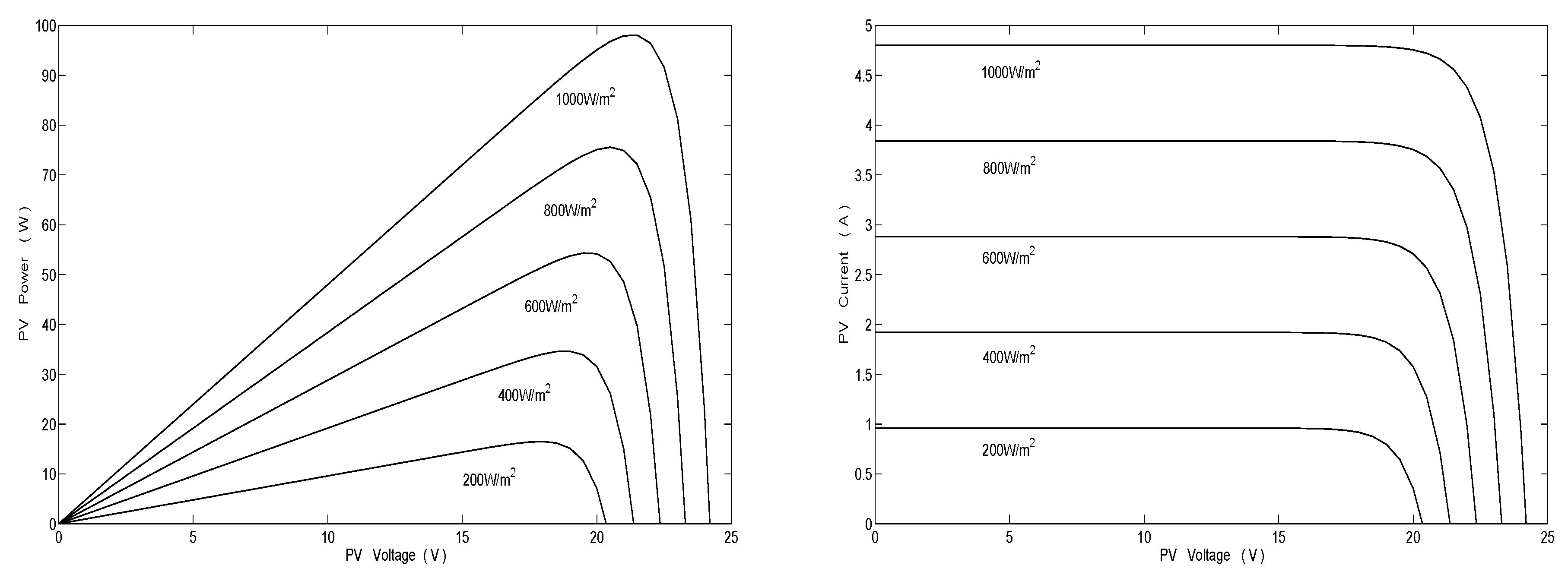
As an example, the PV module composed of three cell in series on the basis of STP0950S-36 PV array was considered. The parameters of each PV cell and the DC-DC converter are shown in Table A1 in Appendix A. According to the PV model in Equation (2) in Section 2.1, each PV cell power and current characteristics under different illumination intensity at 25 C are shown in Figure 6.
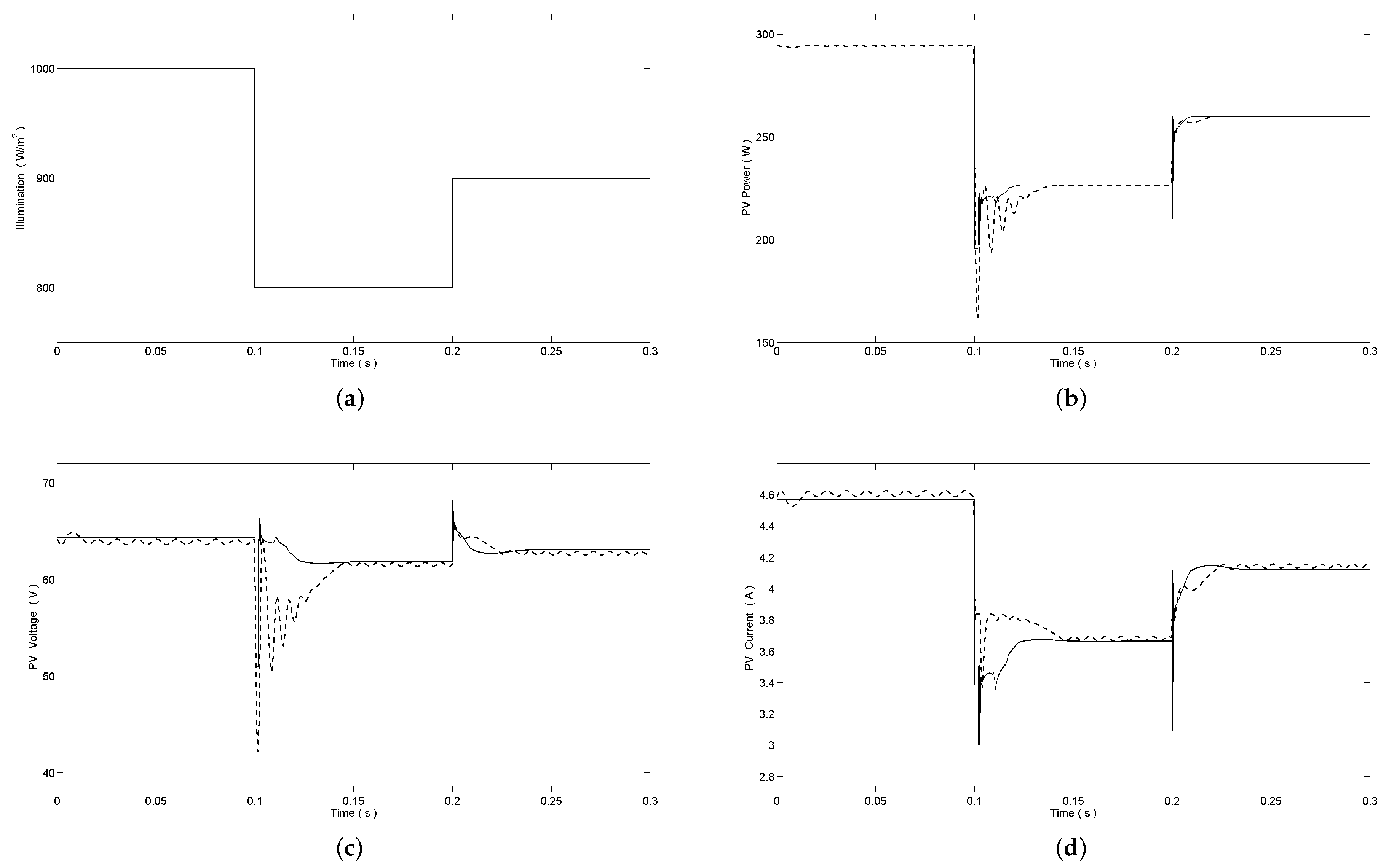
Figure 7 shows the output response of power, voltage and current of the PV cell module under the sudden variation of illumination intensity. For comparison, the traditional P&O algorithm was also applied to MPPT control of the PV system and the simulation results are depicted in Figure 7 as dashed lines. At time s, the illumination intensity changes from 1000 W/m to 800 W/m, and at time s, the illumination intensity changes from 800 W/m to 900 W/m. In Figure 7b, we can see that the power of PV module settles at their expected values at the steady state quickly for proposed MPPT scheme, and the overshoot of PV power for proposed MPPT scheme is smaller than the traditional P&O algorithm with variation of the illumination intensity. Meanwhile, the ripples of PV voltage and PV current are smaller than the traditional P&O algorithm. Detailed simulation data results of proposed MPC method and traditional P&O algorithm are given in Table 1. In Table 1, it is obvious that the proposed MPPT method has a shorter settling time and a lower power ripple than the traditional P&O algorithm, which reduces the oscillation of output voltage at the maximum power point.
5.2. Voltage Regulation Simulation
The proposed voltage regulation scheme was next applied to a 24 V∼36 V buck converter. The parameters of DC-DC buck converter are shown in Table A1 in Appendix A, and the controller parameters were chosen as
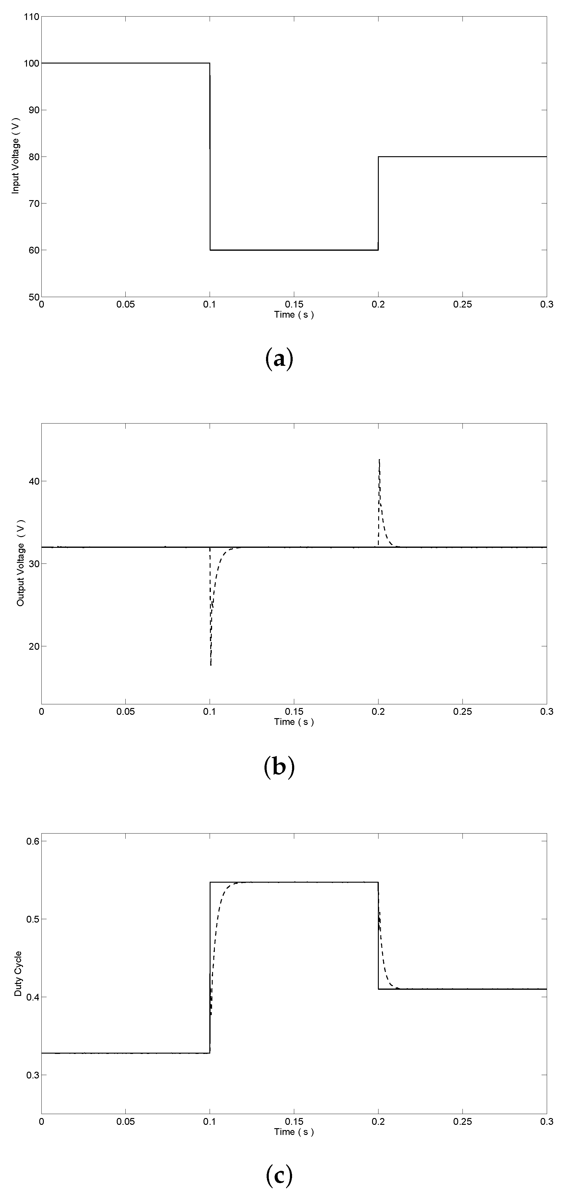
With the step change of the illumination intensity, the output voltage of the PV module changes by the proposed MPPT method via boost converter. Considering the impact of different illumination, the wide range of step change would be chosen to simulate the output voltage of the boost converter, i.e., at time s, the input voltage of the buck converter changes from 100 V to 60 V and the step-down change of input voltage is from 60 V to 80 V at s. Assume the reference output voltage V and the voltage response of DC-DC buck converter is illustrated in Figure 8b. The output voltage of proposed voltage regulation method is maintained at 32 V without overshoot. As comparisons, the simulation results of the traditional PI cascade control method are also given in Figure 8 as dashed lines. In Figure 8b,c, we can see that the response time of duty cycle is longer and the voltage overshoot is 14.4 V and 10.7 V by PI cascade control method respectively, while the control input (duty cycle) obtained by the proposed control scheme varies very quickly to ensure that output voltage of DC-DC buck converter remains practically unaffected while satisfying the input constraints.
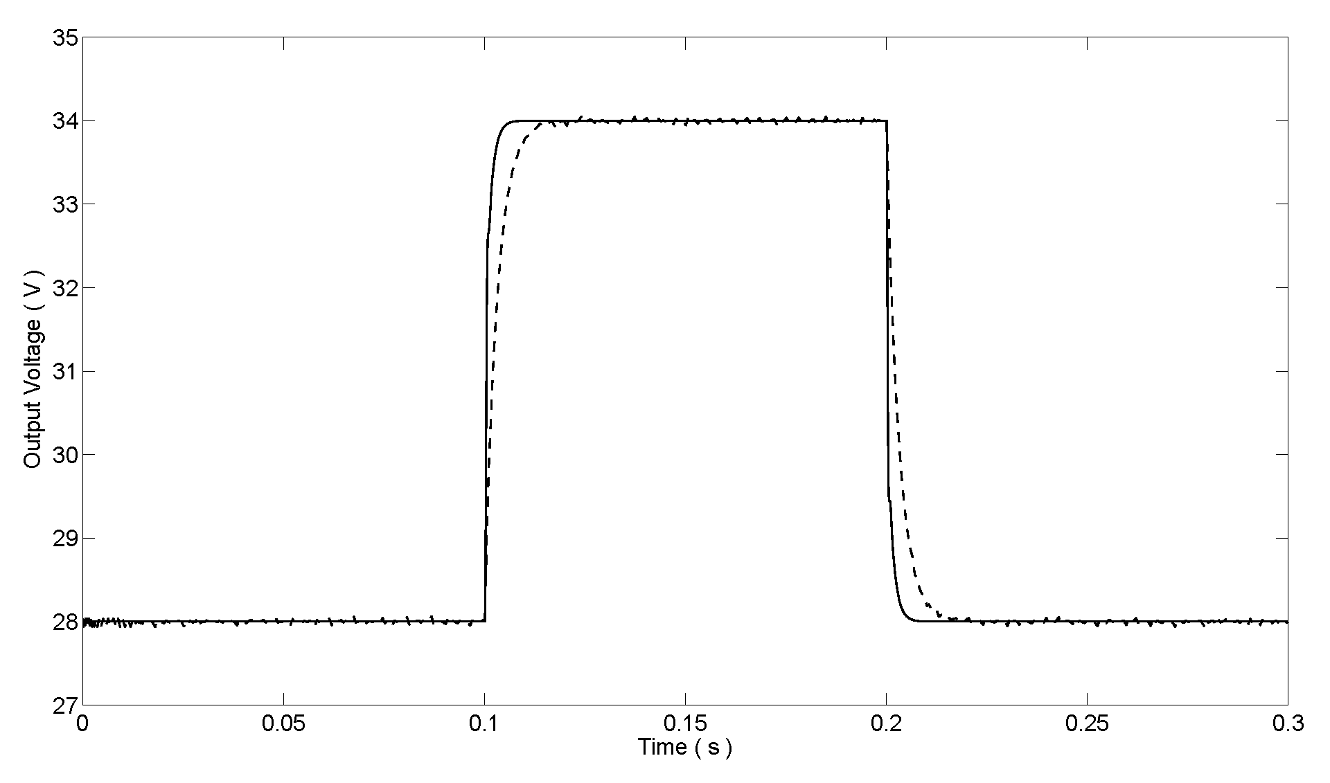
The next simulation was performed with step changes in the reference voltage to show the regulation performance. Firstly, a step-up change of reference voltage from 28 V to 34 V at s and a step-down change from 34 V to 28 V at s were given, and the corresponding response results are illustrated in Figure 9. The output voltage of the proposed voltage regulation method is maintained at the reference voltage quickly. The response time of voltage regulation is 0.007 s in both step changes. However, the simulation results of the traditional PI cascade control method show the response time of voltage regulation is 0.017 s and 0.024 s, respectively. Consequently, the response time of the proposed MPC voltage regulation method is much shorter than the traditional PI cascade control.
5.3. MPPT and Voltage Regulation Simulation
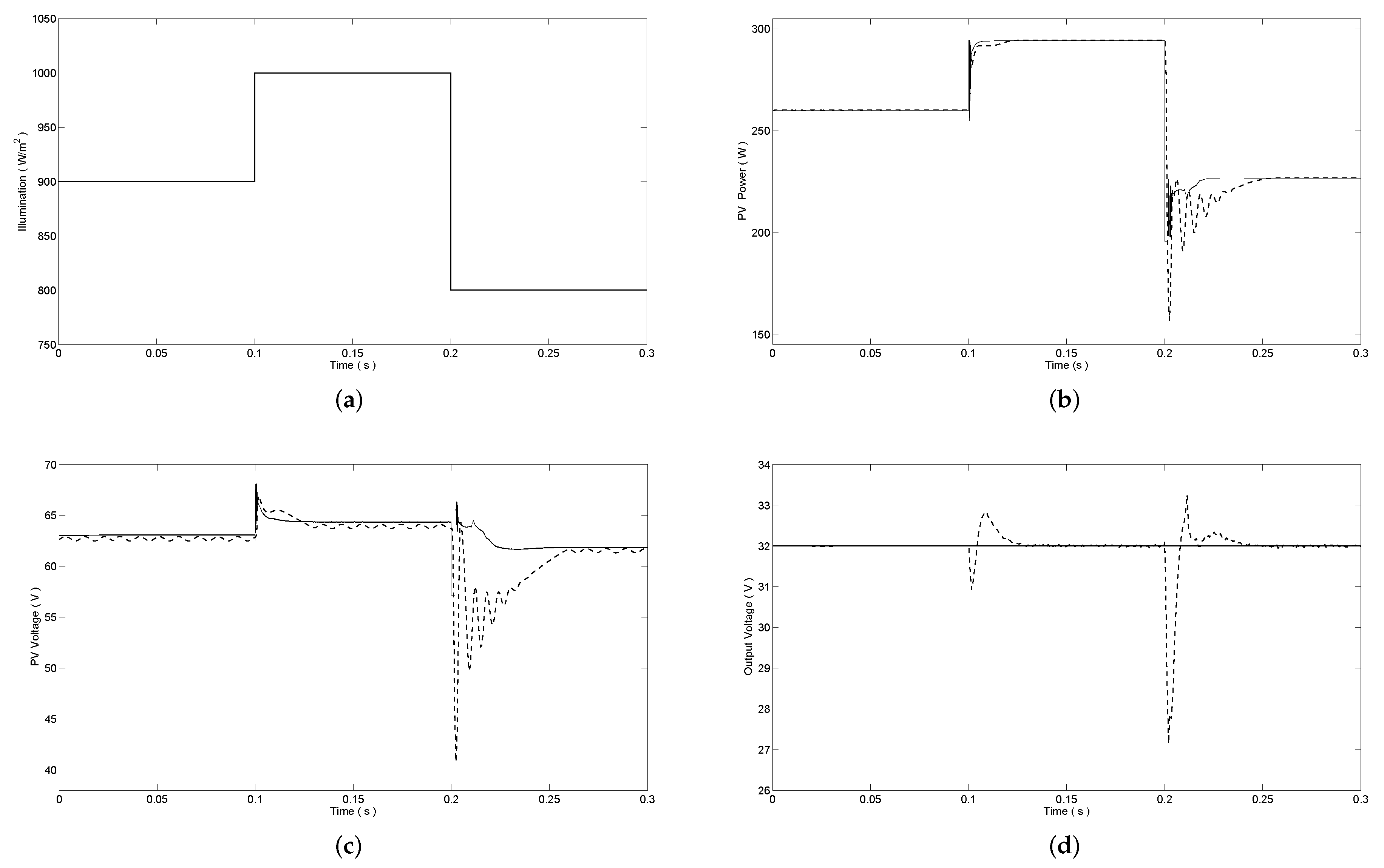
The simulation of the MPPT and voltage regulation of the PV system was studied next. The reference output voltage V was chosen and the simulation results are shown in Figure 10. The illumination intensity changes from 900 W/m to 1000 W/m at time s and changes from 1000 W/m to 800 W/m at time s, as illustrated in Figure 10a. For comparison, we combined the traditional P&O algorithm for MPPT and the PI cascade control method for voltage regulation to design the combined controller. The simulation results of the traditional P&O and PI cascade control for two-stage PV system are also illustrated in Figure 10 as dashed lines. In Figure 10b, we can see that the proposed MPPT method tracks the maximum power point of the PV module at 0.107 s and 0.222 s under the variation of illumination intensity, respectively. The overshoot of PV power for the proposed MPPT scheme is smaller than the traditional P&O algorithm. In Figure 10c, the ripple of PV voltage is smaller comparing with the traditional PI cascade control method. Meanwhile, as shown in Figure 10d, the output voltage of proposed PV system is always maintained at 32 V without overshoot, while the overshoot of output voltage for traditional P&O and PI cascade control is 1.17 V and 5.05 V, respectively, which verifies the effectiveness of the proposed MPPT and voltage regulation methods.
6. Conclusions
This paper proposes the cascaded MPPT and cascade voltage regulation control strategy based on MPC for the two-stage grid-tied PV system, which can achieve MPPT and output voltage regulation of PV system, simultaneously. The proposed MPPT method based on MPC tracks the maximum power point of PV cell module via DC-DC boost converter. The dual step I&C algorithm is used to obtain the reference voltage at maximum power point, and the different step sizes are set under a rapidly changing illumination condition, which can reduce the oscillation deviation of PV output power. Moreover, the proposed MPPT controller based on MPC predicts the future average current of PV cell and only needs to minimize a cost function without PWM module. Consequently, the design of both hardware and software are simplified. In addition, the voltage control method based on MPC is applied to the DC-DC buck converter. The MPC controller outputs the optimal duty signal with the input and state constraints in inner loop, and the PI controller in outer loop is designed to enhance the dynamic performance of DC-DC buck converter, which improves the response speed and reduces the overshoot for output voltage regulation of PV system. Further, the proposed MPC-based method was demonstrated using SimPower systems tool in MATLAB/Simulink. The simulation results show that the proposed MPPT method could achieve the fast response and low output ripple of the PV system, and the fast dynamic performance of the voltage regulation method was also verified.
Author Contributions
Conceptualization, M.M.; methodology, M.M.; software, M.M.; validation, M.M.; formal analysis, M.M.; investigation, M.M. and X.L.; resources, M.M.; data curation, M.M.; writing—original draft preparation, M.M.; writing—review and editing, K.Y.L.; visualization, M.M.; supervision, X.L. and K.Y.L.; project administration, M.M.; funding acquisition, M.M. All authors have read and agreed to the published version of the manuscript.
Funding
This work was financially supported by the National Nature Science Foundation of China (No. 61873091) and the Fundamental Research Funds for the Central Universities (No. 2017ZZD004).
Conflicts of Interest
The authors declare no conflict of interest.
Appendix A

Table A1.
The key parameters of PV system.
| Parameter | Value |
|---|---|
| PV cell | |
| open-circuit voltage () | 24.2 V |
| short-circuit current () | 4.8 A |
| maximum voltage () | 21.7 V |
| maximum current () | 4.5 A |
| maximum power () | 97 W |
| DC-DC boost converter | |
| inductance (L) | 50 mH |
| capacitance (C) | 800 uF |
| load resistance (R) | 10 |
| switch on-resistance () | Ignore |
| diode forward voltage () | Ignore |
| switching frequency (f) | 10 kHz |
| sampling time () | 10 s |
| DC-DC buck converter | |
| inductance (L) | 0.4 mH |
| capacitance (C) | 100 uF |
| load resistance (R) | 10 |
| switch on-resistance () | 0.3 |
| diode forward voltage () | 0.7 V |
| switching frequency (f) | 10 kHz |
| sampling time () | 10 s |
References
- Tofoli, F.L.; Pereira, D.C.; Paula, W.J.; Junior, D.S.O. Survey on non-isolated high-voltage step-up DC-DC topologies based on the boost converter. IET Power Electron. 2015, 8, 2044–2057. [Google Scholar] [CrossRef] [Green Version]
- Forouzesh, M.; Siwakoti, Y.P.; Gorji, S.A.; Blaabjerg, F.; Lehman, B. Step-up DC-DC converters: A comprehensive review of voltage boosting techniques, topologies, and applications. IEEE Trans. Power Electron. 2017, 32, 9143–9178. [Google Scholar] [CrossRef]
- Basha, C.H.; Rani, C. Different Conventional and Soft Computing MPPT Techniques for Solar PV Systems with High Step-Up Boost Converters: A Comprehensive Analysis. Energies 2020, 13, 371. [Google Scholar] [CrossRef] [Green Version]
- Radwan, E.; Nour, M.; Awada, E.; Baniyounes, A. Fuzzy Logic Control for Low-Voltage Ride-Through Single-Phase Grid-Connected PV Inverter. Energies 2019, 12, 4796. [Google Scholar] [CrossRef] [Green Version]
- Costanzo, L.; Vitelli, M. A Novel MPPT Technique for Single Stage Grid-Connected PV Systems: T4S. Energies 2019, 12, 4501. [Google Scholar] [CrossRef] [Green Version]
- Suntio, T.; Kuperman, A. Maximum Perturbation Step Size in MPP-Tracking Control for Ensuring Predicted PV Power Settling Behavior. Energies 2019, 12, 3984. [Google Scholar] [CrossRef] [Green Version]
- Lee, H.S.; Yun, J.J. Advanced MPPT Algorithm for Distributed Photovoltaic Systems. Energies 2019, 12, 3576. [Google Scholar] [CrossRef] [Green Version]
- Bjaoui, M.; Khiari, B.; Benadli, R.; Memni, M.; Sellami, A. Practical Implementation of the Backstepping Sliding Mode Controller MPPT for a PV-Storage Application. Energies 2019, 12, 3539. [Google Scholar] [CrossRef] [Green Version]
- Bani Salim, M.; Hayajneh, H.S.; Mohammed, A.; Ozcelik, S. Robust Direct Adaptive Controller Design for Photovoltaic Maximum Power Point Tracking Application. Energies 2019, 12, 3182. [Google Scholar] [CrossRef] [Green Version]
- Ali, K.; Khan, L.; Khan, Q.; Ullah, S.; Ahmad, S.; Mumtaz, S.; Karam, F.W.; Naghmash. Robust Integral Backstepping Based Nonlinear MPPT Control for a PV System. Energies 2019, 12, 3180. [Google Scholar] [CrossRef] [Green Version]
- Bouarroudj, N.; Boukhetala, D.; Feliu-Batlle, V.; Boudjema, F.; Benlahbib, B.; Batoun, B. Maximum Power Point Tracker Based on Fuzzy Adaptive Radial Basis Function Neural Network for PV-System. Energies 2019, 12, 2827. [Google Scholar] [CrossRef] [Green Version]
- Gil-Antonio, L.; Saldivar, B.; Portillo-Rodríguez, O.; Ávila Vilchis, J.; Martínez-Rodríguez, P.; Martínez-Méndez, R. Flatness-Based Control for the Maximum Power Point Tracking in a Photovoltaic System. Energies 2019, 12, 1843. [Google Scholar] [CrossRef] [Green Version]
- Subudhi, B.; Pradhan, R. A comparative study on maximum power point tracking techniques for photovoltaic power systems. IEEE Trans. Sustain. Energy 2012, 4, 89–98. [Google Scholar] [CrossRef]
- Jayalakshmi, N.S.; Gaonkar, D.N.; Adarsh, S.; Sunil, S. A control strategy for power management in a PV-battery hybrid system with MPPT. In Proceedings of the IEEE International Conference on Power Electronics, Intelligent Control and Energy Systems, Delhi, India, 4–6 July 2016; pp. 1–6. [Google Scholar]
- Mohanty, S.; Subudhi, B.; Ray, P.K. A grey wolf assisted perturb & observe MPPT algorithm for a photovoltaic power system. IEEE Trans. Energy Convers. 2017, 32, 340–347. [Google Scholar]
- Silva, S.A.O.; Sampaio, L.P.; Oliveira, F.M.; Durand, F.R. Feed-forward DC-bus control loop applied to a single-phase grid-connected PV system operating with PSO-based MPPT technique and active power-line conditioning. IET Renew. Power Gener. 2017, 11, 183–193. [Google Scholar] [CrossRef]
- Narendiran, S.; Sahoo, S.K.; Sahoo, A.K. Fuzzy logic controller based maximum power point tracking for PV system. In Proceedings of the International Conference on Electrical Energy Systems, Chennai, India, 17–19 March 2016; pp. 29–34. [Google Scholar]
- Mohamed, A.A.S.; Berzoy, A.; Mohammed, O.A. Design and hardware implementation of FL-MPPT control of PV systems based on GA and small-signal analysis. IEEE Trans. Sustain. Energy 2017, 8, 279–290. [Google Scholar] [CrossRef]
- Khateb, A.E.; Rahim, N.A.; Selvaraj, J.; Uddin, M.N. Fuzzy-logic-controller-based SEPIC converter for maximum power point tracking. IEEE Trans. Ind. Appl. 2014, 50, 2349–2358. [Google Scholar] [CrossRef]
- Shadmand, M.B.; Balog, R.S.; Abu-Rub, H. Model predictive control of PV sources in a smart DC distribution system: Maximum power point tracking and droop control. IEEE Trans. Energy Convers. 2014, 29, 913–921. [Google Scholar] [CrossRef]
- Metry, M.; Shadmand, M.B.; Balog, R.S.; Abu-Rub, H. MPPT of photovoltaic systems using sensorless current-based model predictive control. IEEE Trans. Ind. Appl. 2017, 53, 1157–1167. [Google Scholar] [CrossRef]
- Metry, M.; Bayhan, S.; Balog, R.S.; Rub, H.A. Model predictive control for PV maximum power point tracking of single-phase submultilevel inverter. In Proceedings of the IEEE Power and Energy Conference at Illinois, Urbana, IL, USA, 9–20 February 2016; pp. 1–8. [Google Scholar]
- Mosa, M.; Shadmand, M.B.; Balog, R.S.; Rub, H.A. Efficient maximum power point tracking using model predictive control for photovoltaic systems under dynamic weather condition. IET Renew. Power Gener. 2017, 11, 1401–1409. [Google Scholar] [CrossRef]
- Abushaiba, A.A.; Eshtaiwi, S.M.M.; Ahmadi, R. A new model predictive based maximum power point tracking method for photovoltaic applications. In Proceedings of the IEEE International Conference on Electro Information Technology, Grand Forks, ND, USA, 19–21 May 2016; pp. 571–575. [Google Scholar]
- Park, H.H.; Cho, G.H. A DC-DC converter for a fully integrated PID compensator with a single capacitor. IEEE Trans. Circuits Syst. II Express Briefs 2014, 61, 629–633. [Google Scholar] [CrossRef]
- Jayaprakash, S.; Ramakrishnan, V. Analysis of solar based closed loop DC-DC converter using PID and fuzzy logic control for separately excited motor drive. In Proceedings of the Emerging Trends in New & Renewable Energy Sources and Energy Management, Chennai, India, 16–17 December 2015; pp. 118–122. [Google Scholar]
- Sulligoi, G.; Bosich, D.; Giadrossi, G.; Zhu, L.; Cupelli, M.; Monti, A. Multiconverter medium voltage DC power systems on ships: Constant-power loads instability solution using linearization via state feedback control. IEEE Trans. Smart Grid 2017, 5, 2543–2552. [Google Scholar] [CrossRef]
- Jeung, Y.C.; Choi, I.C.; Lee, D.C. Robust voltage control of dual active bridge DC-DC converters using sliding mode control. In Proceedings of the Power Electronics and Motion Control Conference, Hefei, China, 22–26 May 2016; pp. 629–634. [Google Scholar]
- Ling, R.; Shu, Z.H.; Hu, Q.; Song, Y.D. Second-order sliding-mode controlled three level Buck DC-DC converters. IEEE Trans. Ind. Electron. 2017, 65, 898–906. [Google Scholar] [CrossRef]
- Sahraoui, H.; Drid, S.; Chrifi-Alaoui, L.; Hamzaoui, M. Voltage control of DC-DC Buck converter using second order sliding mode control. In Proceedings of the International Conference on Control, Engineering & Information Technology, Tlemcen, Algeria, 25–27 May 2015; pp. 1–5. [Google Scholar]
- Wei, Q.; Wu, B.; Xu, D.W. Model predictive control of capacitor voltage balancing for cascaded modular DC-DC converters. IEEE Trans. Power Electron. 2016, 32, 752–761. [Google Scholar] [CrossRef]
- Han, W.; Lu, Z.; Jun, Y.; Li, S.H. Model predictive control for DC-DC Buck power converter-DC motor system with uncertainties using a GPI observer. In Proceedings of the 2017 36th Chinese Control Conference (CCC), Dalian, China, 26–28 July 2017; pp. 4906–4911. [Google Scholar]
- Cavanini, L.; Cimini, G.; Ippoliti, G.; Bemporad, A. Model predictive control for pre-compensated voltage mode controlled DC-DC converters. IET Control Theory Appl. 2017, 11, 2514–2520. [Google Scholar] [CrossRef] [Green Version]
- Cavanini, L.; Cimini, G.; Ippoliti, G. Model predictive control for the reference regulation of current mode controlled DC-DC converters. In Proceedings of the IEEE International Conference on Industrial Informatics, Emden, Germany, 24–26 July 2017; pp. 74–79. [Google Scholar]
- Mira, M.C.; Knott, A.; Thomsen, O.C.; Andersen, M.A.E. Boost converter with combined control loop for a stand-alone photovoltaic battery charge system. In Proceedings of the 2013 IEEE 14th Workshop on Control and Modeling for Power Electronics (COMPEL), Salt Lake City, UT, USA, 23–26 June 2013; pp. 1–8. [Google Scholar]
- Qin, L.; Xie, S.; Hu, M.; Yang, C. Stable operating area of photovoltaic cells feeding DC-DC converter in output voltage regulation mode. IET Renew. Power Gener. 2015, 9, 970–981. [Google Scholar] [CrossRef]
- Rekioua, D.; Matagne, E. Optimization of Photovoltaic Power Systems: Modelization, Simulation and Control; Springer: London, UK, 2012. [Google Scholar]
- Singer, S.; Rozenshtein, B.; Surazi, S. Characterization of PV array output using a small number of measured parameters. Sol. Energy 1984, 32, 603–607. [Google Scholar] [CrossRef]
- Ang, S.; Oliva, A. Power-Switching Converters, 3rd ed.; CRC PR INC.: Boca Raton, FL, USA, 2010. [Google Scholar]
- Blanchette, H.F.; Ould-Bachir, T.; David, J.P. A state-space modeling approach for the FPGA-based real-time simulation of high switching frequency power converters. IEEE Trans. Ind. Electron. 2012, 59, 4555–4567. [Google Scholar] [CrossRef]
- Ohtsuka, T. A continuation/GMRES method for fast algorithm of nonlinear receding horizon control. Automatica 2004, 40, 563–574. [Google Scholar] [CrossRef]
- Xu, F.; Chen, H.; Gong, X.; Mei, Q. Fast Nonlinear Model Predictive Control on FPGA Using Particle Swarm Optimization. IEEE Trans. Ind. Electron. 2016, 63, 310–321. [Google Scholar] [CrossRef]
Figure 1.
Two-stage grid-tied PV system topology.

Figure 2.
The topology of DC-DC boost converter.

Figure 3.
Flowchart to determine reference current by dual step I&C algorithm.

Figure 4.
Control system structure of DC-DC boost converter.

Figure 5.
The block diagram of voltage regulation.

Figure 6.
Characteristics of PV power and PV current with PV voltage for each PV cell under different illumination intensity.
Figure 6.
Characteristics of PV power and PV current with PV voltage for each PV cell under different illumination intensity.

Figure 7.
(a) The illumination variation; (b) corresponding output power; (c) output voltage; and (d) output current of PV module (proposed MPPT method (―), traditional P&O algorithm ()).
Figure 7.
(a) The illumination variation; (b) corresponding output power; (c) output voltage; and (d) output current of PV module (proposed MPPT method (―), traditional P&O algorithm ()).

Figure 8.
(a) The input voltage; (b) corresponding output voltage regulation; and (c) duty cycle input of DC-DC buck converter (proposed voltage regulation method (―), PI cascade control ()).
Figure 8.
(a) The input voltage; (b) corresponding output voltage regulation; and (c) duty cycle input of DC-DC buck converter (proposed voltage regulation method (―), PI cascade control ()).

Figure 9.
Output voltage of DC-DC buck converter with reference voltage change (proposed voltage regulation method (―), PI cascade control ()).
Figure 9.
Output voltage of DC-DC buck converter with reference voltage change (proposed voltage regulation method (―), PI cascade control ()).

Figure 10.
(a) The illumination variation; (b) corresponding output power; (c) output voltage of PV module; and (d) output voltage of DC-DC buck converter (proposed method (―), traditional P&O and PI cascade control ()).
Figure 10.
(a) The illumination variation; (b) corresponding output power; (c) output voltage of PV module; and (d) output voltage of DC-DC buck converter (proposed method (―), traditional P&O and PI cascade control ()).

Table 1.
The simulation data of PV module.
| Illumination | Settling Time | Power Ripple | |
|---|---|---|---|
| 1000 | MPC | ― | 0.0776 W |
| P&O | ― | 0.1136 W | |
| 800 | MPC | 0.024 s | 0.0325 W |
| P&O | 0.043 s | 0.0625 W | |
| 900 | MPC | 0.012 s | 0.0354 W |
| P&O | 0.025 s | 0.0726 W |
© 2020 by the authors. Licensee MDPI, Basel, Switzerland. This article is an open access article distributed under the terms and conditions of the Creative Commons Attribution (CC BY) license (http://creativecommons.org/licenses/by/4.0/).
Share and Cite
MDPI and ACS Style
Ma, M.; Liu, X.; Lee, K.Y. Maximum Power Point Tracking and Voltage Regulation of Two-Stage Grid-Tied PV System Based on Model Predictive Control. Energies 2020, 13, 1304. https://0-doi-org.brum.beds.ac.uk/10.3390/en13061304
AMA Style
Ma M, Liu X, Lee KY. Maximum Power Point Tracking and Voltage Regulation of Two-Stage Grid-Tied PV System Based on Model Predictive Control. Energies. 2020; 13(6):1304. https://0-doi-org.brum.beds.ac.uk/10.3390/en13061304
Chicago/Turabian StyleMa, Miaomiao, Xiangjie Liu, and Kwang Y. Lee. 2020. "Maximum Power Point Tracking and Voltage Regulation of Two-Stage Grid-Tied PV System Based on Model Predictive Control" Energies 13, no. 6: 1304. https://0-doi-org.brum.beds.ac.uk/10.3390/en13061304
Note that from the first issue of 2016, this journal uses article numbers instead of page numbers. See further details here.