Electric Vehicle–Grid Integration with Voltage Regulation in Radial Distribution Networks

1
Department of Electrical and Computer Engineering, Michigan Technological University, 1400 Townsend Dr, Houghton, MI 49931, USA
2
Department of Mechanical Engineering-Engineering Mechanics, Michigan Technological University, 1400 Townsend Dr, Houghton, MI 49931, USA
*
Author to whom correspondence should be addressed.
Energies 2020, 13(7), 1802; https://0-doi-org.brum.beds.ac.uk/10.3390/en13071802
Submission received: 10 March 2020
/
Revised: 27 March 2020
/
Accepted: 31 March 2020
/
Published: 8 April 2020
(This article belongs to the Special Issue Electric Systems for Transportation)
Abstract
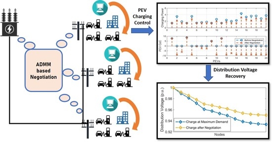
:In this paper, a vehicle–grid integration (VGI) control strategy for radial power distribution networks is presented. The control schemes are designed at both microgrid level and distribution level. At the VGI microgrid level, the available power capacity for electric vehicle (EV) charging is optimally allocated for charging electric vehicles to meet charging requirements. At the distribution grid level, a distributed voltage compensation algorithm is designed to recover voltage violation when it happens at a distribution node. The voltage compensation is achieved through a negotiation between the grid-level agent and VGI microgrid agents using the alternating direction method of multipliers. In each negotiation round, individual agents pursue their own objectives. The computation can be carried out in parallel for each agent. The presented VGI control schemes are simulated and verified in a modified IEEE 37 bus distribution system. The simulation results are presented to show the effectiveness of the VGI control algorithms and the effect of algorithm parameters on the convergence of agent negotiation.
1. Introduction
Plug-in electric vehicles (PEVs) have become a practical option for reducing global greenhouse emissions and fossil fuel depletion. However, PEVs also bring challenges to the operation of the power grid if the penetration of PEVs increases. Some of our previous studies [1,2,3] focus on PEV charging scheduling and optimization within a microgrid, such as via load shaping, charging cost minimization, etc. Study [4] uses the real-time simulation method to validate the PEV charging control algorithm in a VGI microgrid. Large-scale PEV charging activities bring more challenges to power distribution grids. Papers [5,6,7] use deterministic and stochastic approaches to analyze the PEV charging impact on the distribution networks, including overloading, transformer aging, voltage drop, frequency deviation, and network operating costs. Investigations have been conducted to mitigate some of the aforementioned grid challenges. For example, Cao, et al. [8] formulate the PEV charging activities in a distribution grid as a generalized Nash equilibrium problem. Without violating the node and substation power limits, a Nikaido–Isoda-based control algorithm is developed to minimize individual customers’ PEV charging costs. Wang et. al, [9] develop a fully distributed consensus-based large-scale PEV charging coordination algorithm in a power distribution grid. The objectives of this development are to minimize the charging power loss and maximize the PEV power for vehicle-to-grid services. In [10], the authors further provide a dual-level consensus-based electric vehicle charging control scheme for distribution grid frequency regulation. The upper-level control aims to minimize the frequency deviation, and the lower-level control aims to minimize the frequency regulation cost and battery degradation.
In a traditional radial distribution grid, power is delivered from the head node to the end node through the feeder line. Our previous study [5] proposes that the reason for the voltage drop is the excessive high load peaks in a distribution grid. The study provides intuitive approaches for PEV charging, load shifting, and curtailment based on the time of use (ToU) and direct load control (DLC) demand response. Though on-board tap changers (OLTC) [11] and capacitor banks [12] are widely used in distribution grids for voltage regulation, the OLTC is usually used to regulate a relatively large-area network and only monitors voltage at specific nodes. The capacitor banks, though they react quickly, are not installed throughout the entire network. As a result, these devices lack the flexibility for voltage regulation in distribution networks. Some researchers have studied the possibility of utilizing the re-active power operation of the PEV charger for voltage regulation. For example, the authors in [13] propose a vehicle-to-grid reactive power support strategy in cooperation with a high penetration of distributed generation to provide the distribution grid voltage-regulation service. Paper [14] introduces four operation modes of the PEV charger, which include the combination of charging/discharging and inductive/capacitive operation. Though a bi-directional charger capable of reactive power operation is conceptually feasible [15,16], existing on-board chargers on the market may not have this functionality. In fact, the charging system testing data from [17] show that the on-board chargers of the major PEV models are unidirectional, and the related power factors are stable between 0.95–0.99.
In this paper, we aim to study the capability of PEVs to regulate voltage in a VGI distribution grid. A two-level control system was developed to find a balance between the PEV charging requirement and the distribution grid voltage recovery requirement. The contributions of this paper include:
- A distributed multi-agent negotiation algorithm is developed to recover voltage violation in a distribution network with the alternating direction method of multipliers (ADMM) [18]. In this negotiation algorithm, a series of PEV charging power curtailment decisions are made through a negotiation process. The negotiation agents are the computation and communication units that perform objective pursuit and conduct bargaining in the negotiation. The negotiation agents in this study include multiple VGI microgrid agents who wish to operate the microgrid at a critical charging point for PEVs, and a grid-level agent who wants to recover voltage violation. The negotiation process aims to find a balance between the voltage compensation and the PEV charging requirement.
- The proposed “capacity of curtailment” (CoC)-based optimal VGI microgrid control algorithm is an improvement of the previously developed iterative PEV curtailment control algorithm [19]. The algorithm determines the microgrid PEV charging power capacity either from PEVs’ maximum power demand or base on the distribution grid voltage compensation requirement. With a nonlinear optimization technique, the new algorithm allocates the limited PEV charging power to maximize the infimum of the vehicle CoC value set in a VGI microgrid.
- The effects of negotiation parameters, such as the penalty factor and the proximal factor, on the negotiation convergence and convergence speed are studied. The selection range of these parameters is provided based on our simulation testing.
The rest of the paper is organized as follows: Section 2 provides an overview of a distribution-level VGI system. Section 3 presents the development of a CoC-based optimal VGI microgrid control algorithm. Section 4 gives the formulation of the voltage regulation negotiation in a distributed manner. Section 5 shows the simulation results of a use case study. Section 6 concludes the paper.
2. Overview of Distribution-Level VGI Control
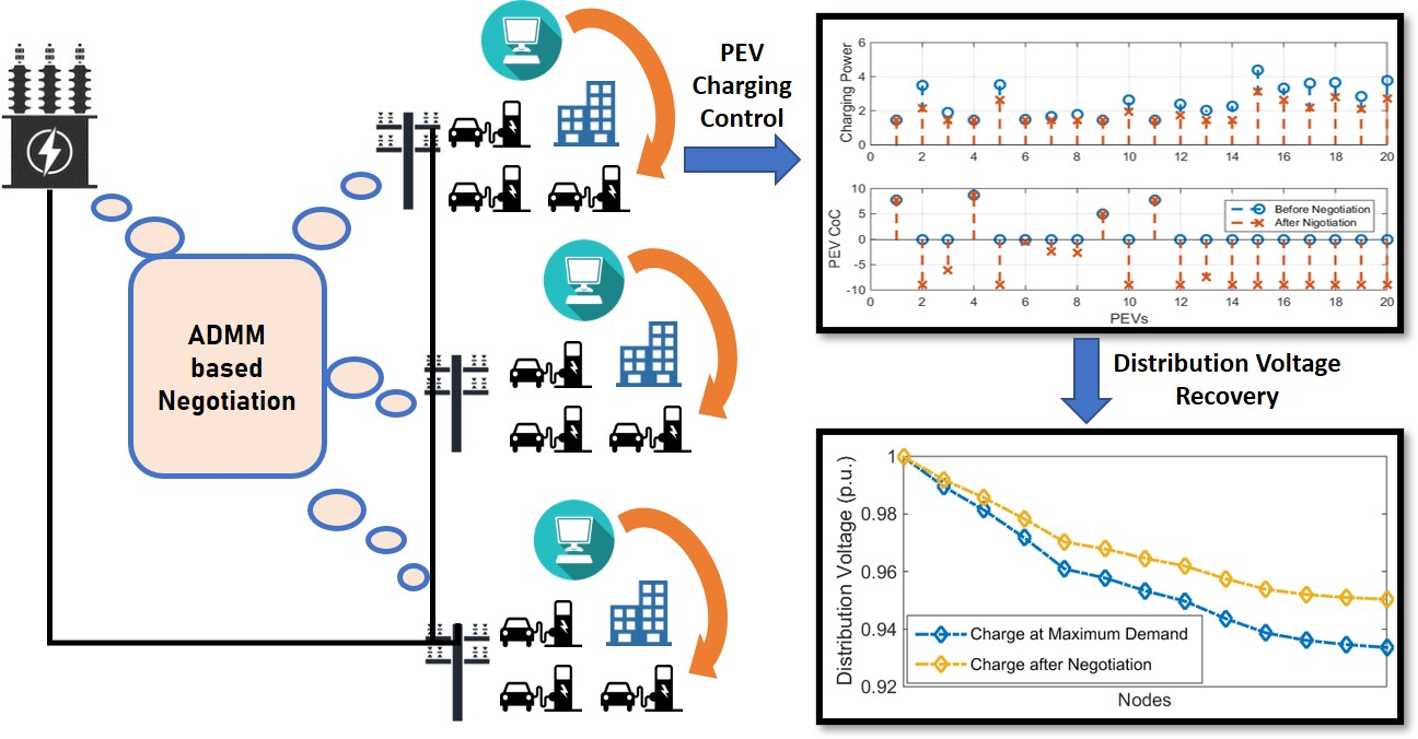
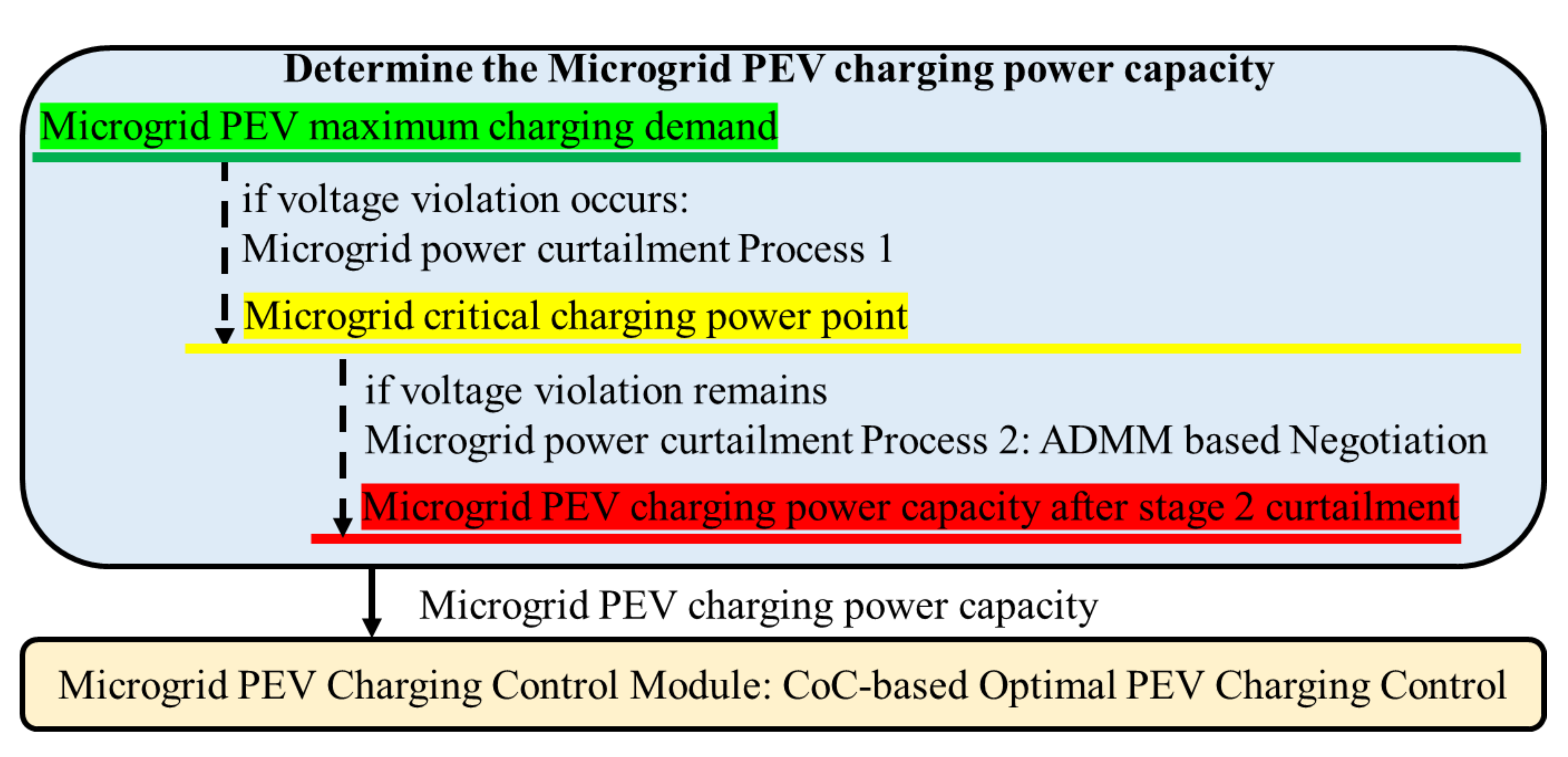
A radial distribution system is the simplest and the most commonly seen power distribution system. When massive electric vehicle charging activities present in a radial distribution system, the system is at the risk of aggravated power loss and excessive voltage drop. A distributed PEV charging management scheme is designed to provide emergent voltage recovery in a distribution grid and PEV charging power allocation at local microgrids. Figure 1 shows the control and communication among the components of a distribution-level VGI system. Over the feeder branch, a grid-level agent takes charge of bus voltage monitoring and voltage regulation. This consists of modules for bus voltage monitoring, voltage–load variation relation analysis, ADMM optimization, and the distributed negotiation service. At each bus, the buildings and PEV charging stations are grouped to form a microgrid-level VGI system. A microgrid agent is composed of the PEV charging control module that is responsible for dispatching the limited charging power to individual PEVs and the ADMM optimization module, which coordinates with other agents during the process of voltage recovery negotiation.
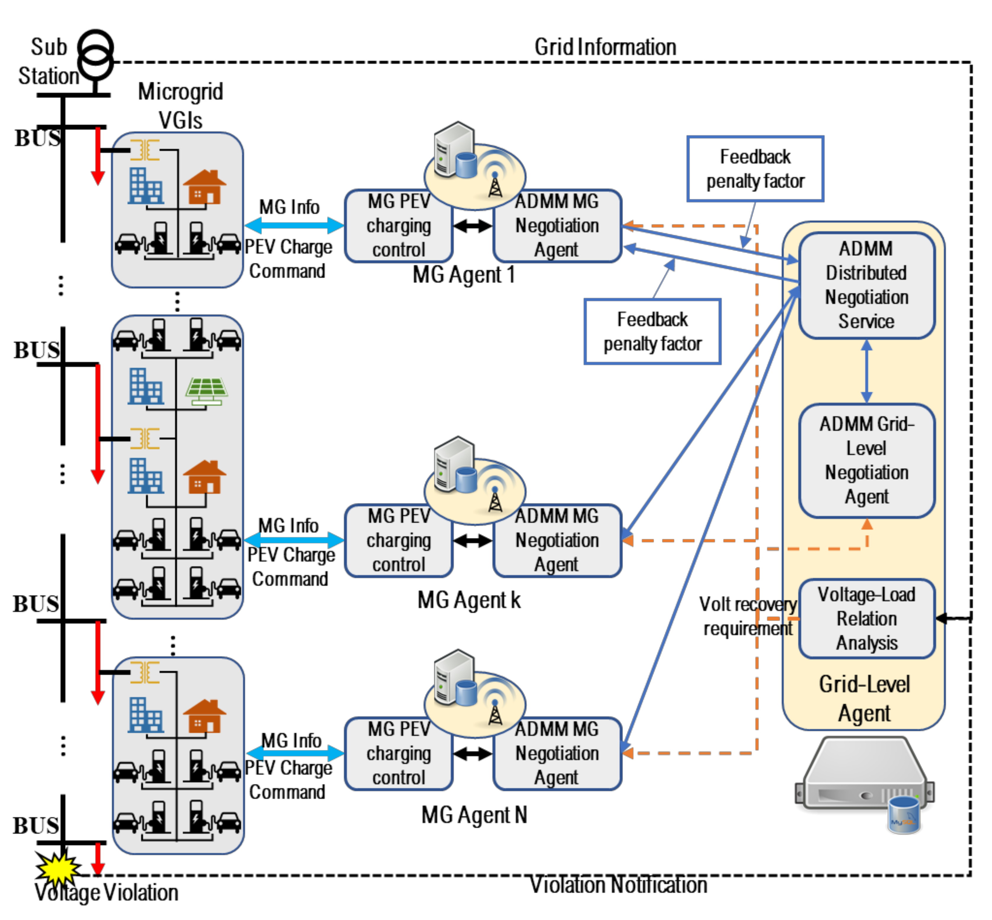
When the grid-level agent senses a voltage violation at a bus, it sends a notification to all the VGI microgrid agents. Each microgrid individually finds and decreases the microgrid PEV charging power to a critical charging power point. This critical charging power point is the lowest microgrid PEV charging power capacity that meets the PEV state of charge (SOC) requirements. If the voltage violation remains, a voltage–load relation analysis is conducted by the grid-level agent. The coefficients of the voltage–load relation, which reflects the impact of the load change of individual microgrids on voltage variation at current violation bus, are broadcasted to all the agents in the network. A negotiation is initiated among all the involved microgrid agents and the grid-level agent. The negotiation uses the ADMM-based method to find out the balance between the load curtailment amount of each microgrid and the voltage recovery requirement. Figure 2 shows the PEV charging power capacity determination process before the microgrid PEV charging control can be applied.
3. Microgrid-Level VGI Control
In this section, a CoC-based optimal VGI microgrid control algorithm is presented, which aims to allocate limited PEV charging power to better meet the PEV charging requirements in a microgrid. The PEV charging process is analyzed based on the steady-state PEV charging test results [17]. The process is divided into two stages: constant power charging and constant voltage charging. In the constant power charging stage, the PEV on-board charger can provide charging power control by specifying the input AC current [20]. When the PEV battery voltage reaches a certain level, the charging enters a constant voltage charging stage in which the PEV charging power decreases gradually. The constant power charging stage is the major controllable period that smart charging schemes are applied to. The VGI microgrid control algorithm is designed with following assumptions.
- The target SOC, departure time, and vehicle type are specified by the PEV charging customers at charging stations.
- All charging PEVs are enrolled in the smart charging control program.
- The Electric Vehicle Supply Equipment (EVSE) can detect the PEV connectivity, the PEV SOC and charging stage. In addition, four control states are defined for an EVSE. State (: there is no PEV connected to the EVSE; State 1 (: a PEV is connected to the EVSE and is in charging stage 1; State 2 (: a PEV is connected to the EVSE and is in the charging stage 2; State 3 ((: reserved for temporary usage.
3.1. The CoC-Based Optimal PEV Charging Control
The concept of capacity of curtailment is defined to evaluate the capability of a PEV to allow charging power curtailment as shown below:
where and represent the current and target state of charge, respectively. denotes the battery charging current at the DC terminal. is the PEV departure time and is the vehicle battery capacity in amp-hours. A positive value of COC means that the target SOC can be reached before the departure time with the current charging power rate. A time-related weighting factor boosts the CoC value when a vehicle approaches its departure time.
The objective of CoC-based optimal VGI microgrid control algorithm is to curtail the charging power of PEVs with higher CoC values and leave the power capacity for the PEVs with lower CoC values when the total charging power of a microgrid is limited. In other word, the set of CoC values of the controllable PEVs in a microgrid is considered as a collection of time-varied functions of the PEV charging power: , where the set represents the set of controllable PEVs. The objective is to calculate the proper charging powers for the controllable PEVs to maximize the infimum of the CoC set as shown in Equation (2).
where y is the infimum, which is the largest value that is smaller than all the CoC values. is the limited charging power of the microgrid. represents the EVSE state. is the feasible range of power consumption of EVSE i, which can be represented as Equation (3)
where is the minimum PEV charging rate when the AC minimum charging current is 6 A. denotes the maximum charging power of the PEV charger.
The CoC-based optimal VGI microgrid control algorithm presents the control design for different available power capacities. If the available charging power is greater than the charging power demand, all the PEVs in charging stage 1 will be charged at the maximum power of the charging stations and the PEVs in charging stage 2 will be charged at the required power for constant voltage charging. If the available charging power is not enough for all connected PEVs even at the minimum charging power, the control scheme temporarily shuts off some of PEVs in charging stage 1. If the available charging power is between the maximum and minimum charging power demands, the optimization is performed to reallocate the charging power to individual PEVs in charging stage 1. If a PEV is being charged at maximum charging power but still has the lowest CoC value, this PEV is considered as an uncontrollable load.
3.2. Microgrid PEV Charging Power Capacity
Before dispatching power to the PEVs, the microgrid needs to determine the PEV charging power capacity, . If there is no distribution voltage violation, all the PEVs obtain as much power as their maximum demands. When voltage violation occurs, a microgrid curtails its PEV charging power capacity to a value, , named as “The critical charging power point”. This is the minimum power capacity that can meet the PEV charging SOC requirement through the microgrid PEV charging control algorithm. The critical charging power point can be obtained by using Equation (4)
where all the are the outputs of the PEV charging control algorithm when applying . If the first process of curtailment does not resolve the voltage violation, a second PEV charging power capacity curtailment process is needed. The further power curtailment is defined as , which is determined through a distributed negotiation process.
| The CoC-based Optimal VGI Microgrid Control Algorithm |
Obtain charging information:
if no voltage violation occurs ; elseif voltage violation occurs Curtailment Process 1: ; if voltage violation remains at Process 1 Curtailment Process 2: ; is the power curtailment decision of the negotiation. Enter the Optimal PEV Charging Control
; elseif Calculate with Sort set in ascending order. Calculate Perform optimization defined in Equation (2) among the first number of PEVs. Shut off charging of rest stage 1 PEVs – set to state 0 else Perform optimization defined in Equation (2) While () set ; Perform optimization defined in Equation (2) |
| Exit |
4. Voltage Compensation in a Distribution-Level VGI System
A voltage compensation process is divided into two parts. In the first part, the voltage–load variation relation analysis is conducted by the grid-level agent. With this relation, the microgrid agents and the grid-level agent negotiate and find out the further power curtailment of the microgrids and the adjusted voltage compensation target.
4.1. The Voltage–Load Variation Relationship Analysis
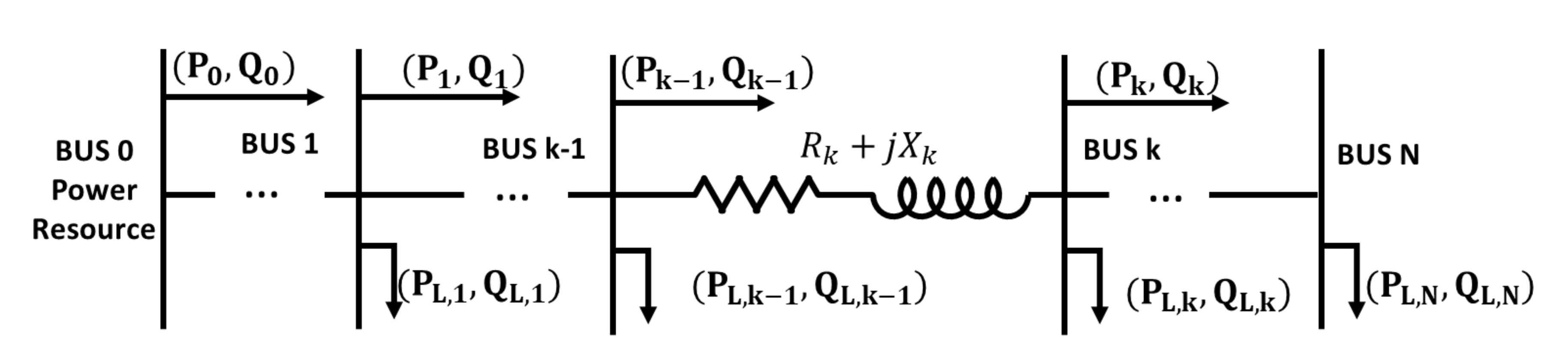
The relationship between the voltage change and the load variation of the nodes is analyzed at the grid-level agent with a Jacobi iterative method. This relationship is useful for the microgrid agents to determine their PEV charging power curtailment and the grid-level agent to adjust its voltage compensation target in performing the voltage regulation. Figure 3 shows a distribution feeder branch from a substation BUS 0 as a power source to the end bus—BUS N. The distribution line section parameters are simplified as an impedance model R + jX. The cross-coupling effects of inductance and shunt capacitance from different phases are not considered.
Based on the results deduced in [12], the active and reactive supply power at a random BUS k can be related to the power loss on the distribution line and the grid parameters of BUS k − 1, as shown in Equations (5) and (6). The voltage relationship between BUS k − 1 and BUS k can also be derived as Equation (7):
The square of the downstream root-mean-square (RMS) voltage square can be represented as a function of its adjacent upper-stream supply power and the square of RMS voltage. It is also related to the distribution line impedance between the two buses. Fazio et. al, [21] provide a proof that a random bus parameter variation can be estimated as a linear combination of all buses’ loads along the distribution feeder and the source voltage variation square. By using Taylor expansion and the chain rule, the voltage–load variation relationship is deduced; the square of RMS voltage variation for a random BUS k can be represented as Equation (8).
The coefficients compose the weighting factor vector that represents the effect of load variation at BUS k on the BUS K RMS voltage square. The values of the coefficients are deduced from [21]. denotes the power source voltage fluctuation. represents the weighting factor between the variation of power source voltage and the BUS k voltage. Considering the power factor of the PEV charging in each microgrid as , the reactive PEV charging power curtailment of a microgrid can be represented as . Assuming that the voltage source does not fluctuate, the distribution voltage improvement at BUS K about power curtailment at each node along the distribution feeder line then can be simplified and reformulated as
where the parameter . The relationship (Equation (9)) is broadcasted to all the voltage recovery participants—the microgrid agents and the grid-level agent.
4.2. The ADMM-Based Voltage Compensation Negotiation
With the voltage–load variation relationship information, a distributed negotiation is triggered to compensate the voltage violation at BUS K in a distribution feeder branch amongst all the agents in the feeder branch. The voltage compensation negotiation aims to maximally recover the voltage back to the allowable range with least sacrifice of PEV charging requirements.
The microgrid agents want to minimize further power curtailment from their critical charging power point. The objective function of microgrid agents are defined in Equation (10).
The objective of the grid-level agent is to meet the distribution voltage compensation target as much as possible. Define the distribution RMS voltage square compensation target as , which is the difference between the target RMS voltage square and the instant RMS voltage square at the violation bus. The value of the target RMS voltage is selected to be a little higher than the distribution voltage lower bound, 0.95 p.u. The objective function of the grid-level agent is represented as Equation (11)
The voltage compensation problem is converted to a coordination problem that balances the objectives of the distribution grid voltage requirement and the PEV charging requirements in multiple microgrids as shown in Equation (12).
This minimization problem is solved using ADMM iteratively. The augmented Lagrangian is expressed as Equation (13) in the first step.
is a vector of microgrid PEV charging power curtailments. The symbol is the Lagrangian multiplier. is called the penalty parameter. The optimal solution set of the voltage compensation and the microgrid PEV charging curtailments can be found through an iterative optimization process as shown in Equation (14).
Due to the separability of the minimization objective (Equation (12)), the update of decision variable can be conducted by each negotiation participant in parallel using the Jacobian type of method. This method fixes variables that are not directly related to a microgrid to the last iteration decisions, therefore simplifies the calculation. Furthermore, a proximal term is added to strengthen the convexity of the augmented Lagragian and accelerate the convergence. The distributed solution of the distribution voltage compensation problem can be achieved through the following iterations.
| Distributed Voltage Compensation Negotiation Process |
Initialization
|
| Exit |
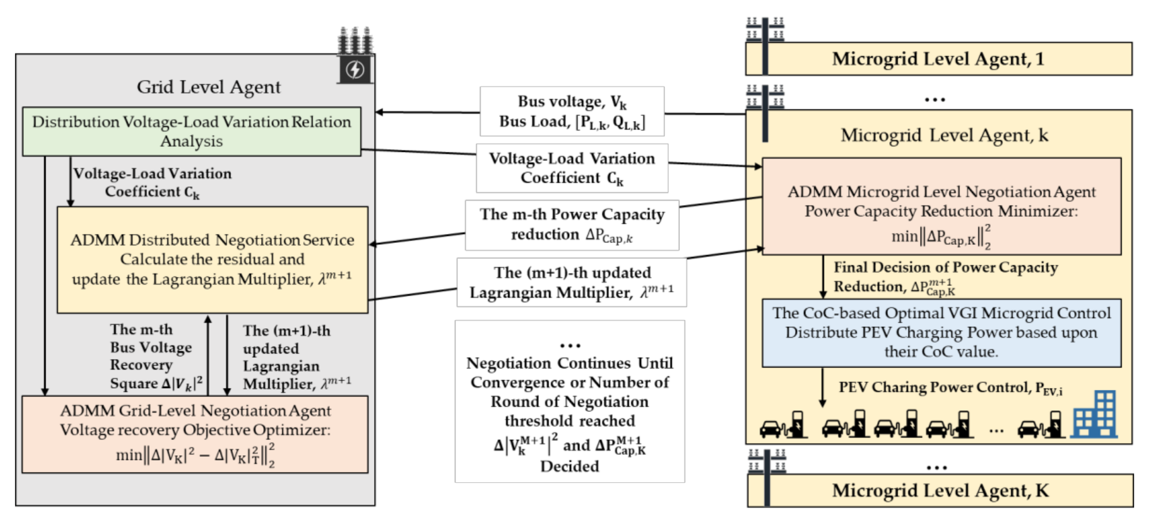
In the negotiation process shown in Figure 4, each participant agent places an initial value for its decision variable, for the grid-level agent and , for each of the microgrid agents, and notifies all other participant agents. Then, with the knowledge of all other agents’ proposed decisions, and the voltage–load variation relationship coefficients, , each participant agent optimizes the augmented Lagrangian with the proximal, considering its own decision as the only variable. Due to the separability of the objective in Equation (12), the optimization conducted by each negotiation participant is closed to its target value with the constraint of the voltage–load variation relationship. In addition, all components of the individual optimization functions are square errors, which are quadratic. This ensures the strict convexity of these functions and guarantees that a unique vector of minimizers can be found in each round of negotiation. The grid-level agent collects all the optimization results from all negotiation participants. The residual is calculated and used to judge if the negotiation agreement is obtained. If the residual is beyond a pre-specified range, a new round of negotiation starts with the updated Lagrangian multiplier, . The negotiation iteration continues until the residual converges to a small enough value. Notice that the selection of the initial values, such as the initial Lagrangian multiplier, , the penalty factor , the proximal factor and VGI microgrid load curtailments can all have the effects on the negotiation convergence. The investigation of these impacts is conducted to ensure the performance of the control scheme.
5. Use Case Study
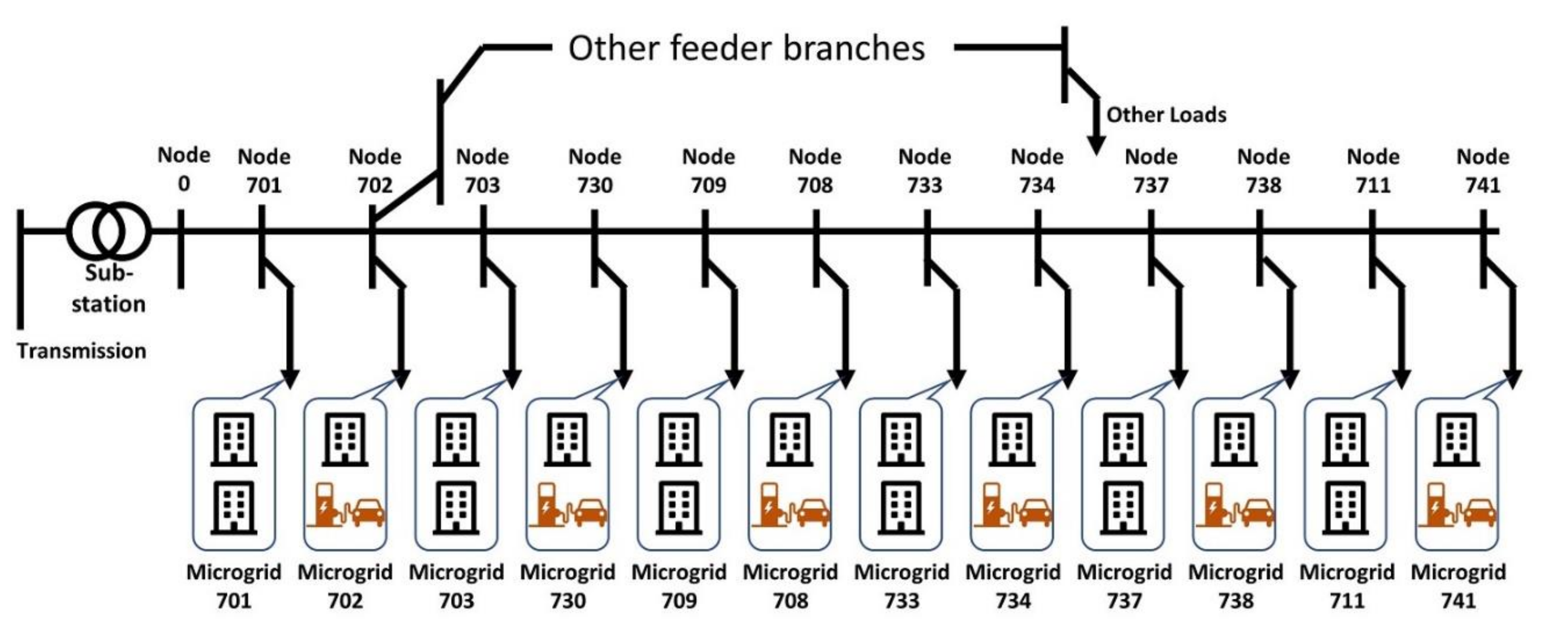
To validate the presented voltage compensation algorithm, the longest branch of the IEEE 37 Node Test feeder [22] from Node 701–Node 741 was selected to simulate a mid-level distribution feeder branch with commercial loads. The transmission voltage level of 230 kV is transformed in distribution substation to 4.8 kV in the feeder. Different combinations of commercial building load profiles obtained from [23] were used as uncontrollable load of microgrids connected to each node. In addition to building loads, microgrids on node 702, 730, 708, 734, 738 and 741 had PEV chargers. Figure 5 shows the distribution grid topology of the use case. The building loads and the number of EVSEs under each node are listed in Table 1. A total of 120 EVSEs were installed in six microgrids to charge three types of PEVs. The PEV battery and charging parameters are listed in Table 2. The power factors of the building load and PEV charger were 0.95 and 0.98, respectively.
We simulated the voltage compensation at 10:00 am and assumed that all the EVSEs were connected with PEVs. This resulted in 120 PEVs (31 Nissan Leaf 2013s, 20 BMW i3 2014s, and 69 Chevy Volt 2013s) in the simulation. These PEVs were randomly allocated to EVSEs. The initial and target SOCs of the PEVs were also randomly generated. Table 3 shows the uncontrollable load and maximal PEV charging power demand at 10:00 am. The variation and effect from other feeder branches are not considered. In addition, it was assumed that the grid was balanced, and the node loads were all connected to the same phase on the feeder branch.
One distribution voltage violation was simulated at Node 741 with 0.933 per unit when all microgrids chose to charge PEVs at maximum charging power. After all microgrids curtailed PEV charging power to critical point, the voltage violation still existed at Node 741 with 0.948 per unit. In this situation, a negotiation among the grid-level agent and microgrid agents to further curtail PEV charging power for the voltage compensation is triggered. Firstly, the voltage–load variation relationship coefficients were found to be coef = [0.2396, 0.4420, 0.7242, 1.0718, 1.1869, 1.3710, 1.5548, 1.8788, 2.2462, 2.4738, 2.6975, 2.9188], which were used as the grid voltage compensation reference. Each VGI microgrid wishes to retain a charging power close to its PEV critical charging power point. On the other hand, the grid-level agent wishes to compensate the voltage at Node 741 back to 0.9505 per unit. The negotiation process is shown in Figure 4.
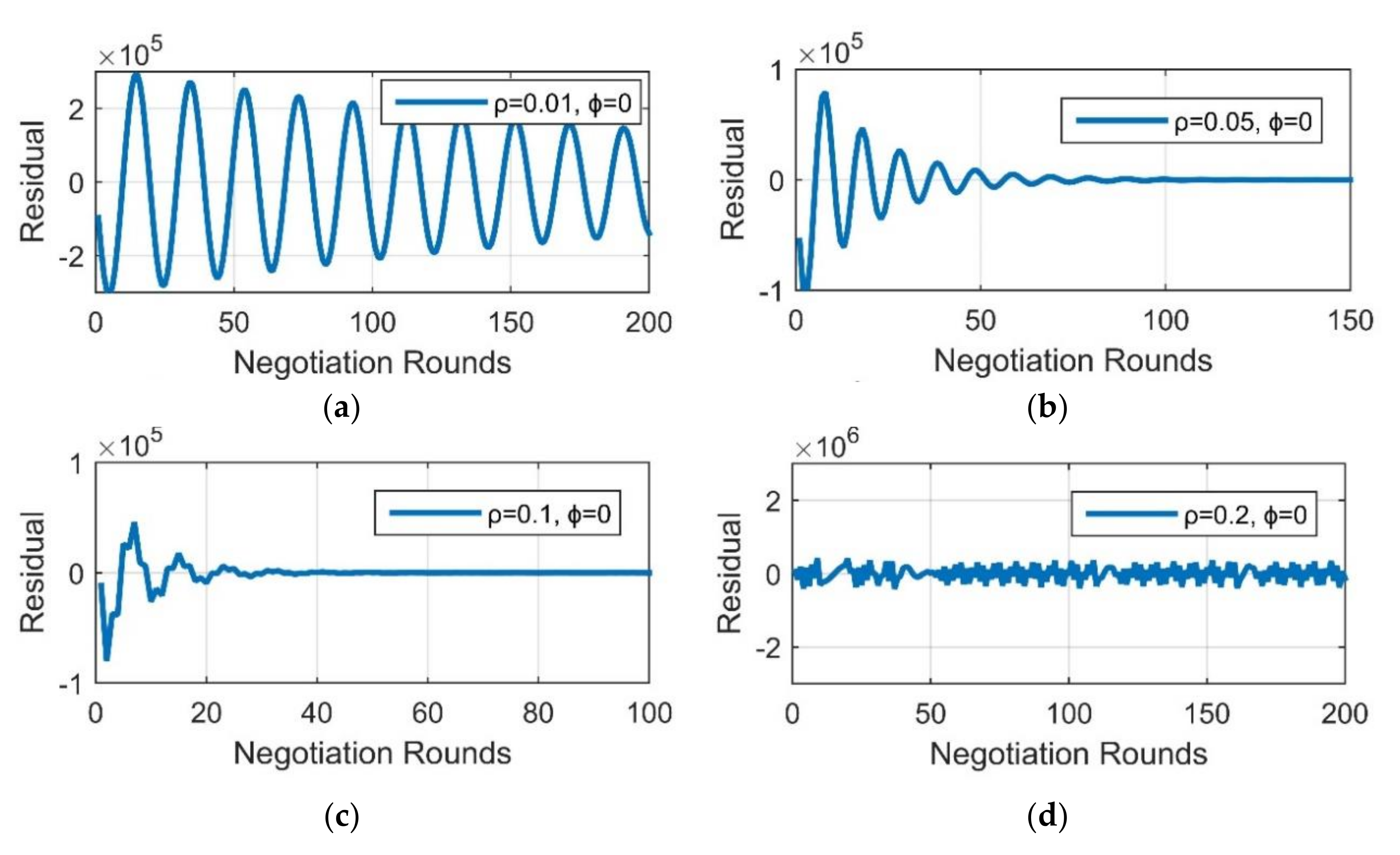
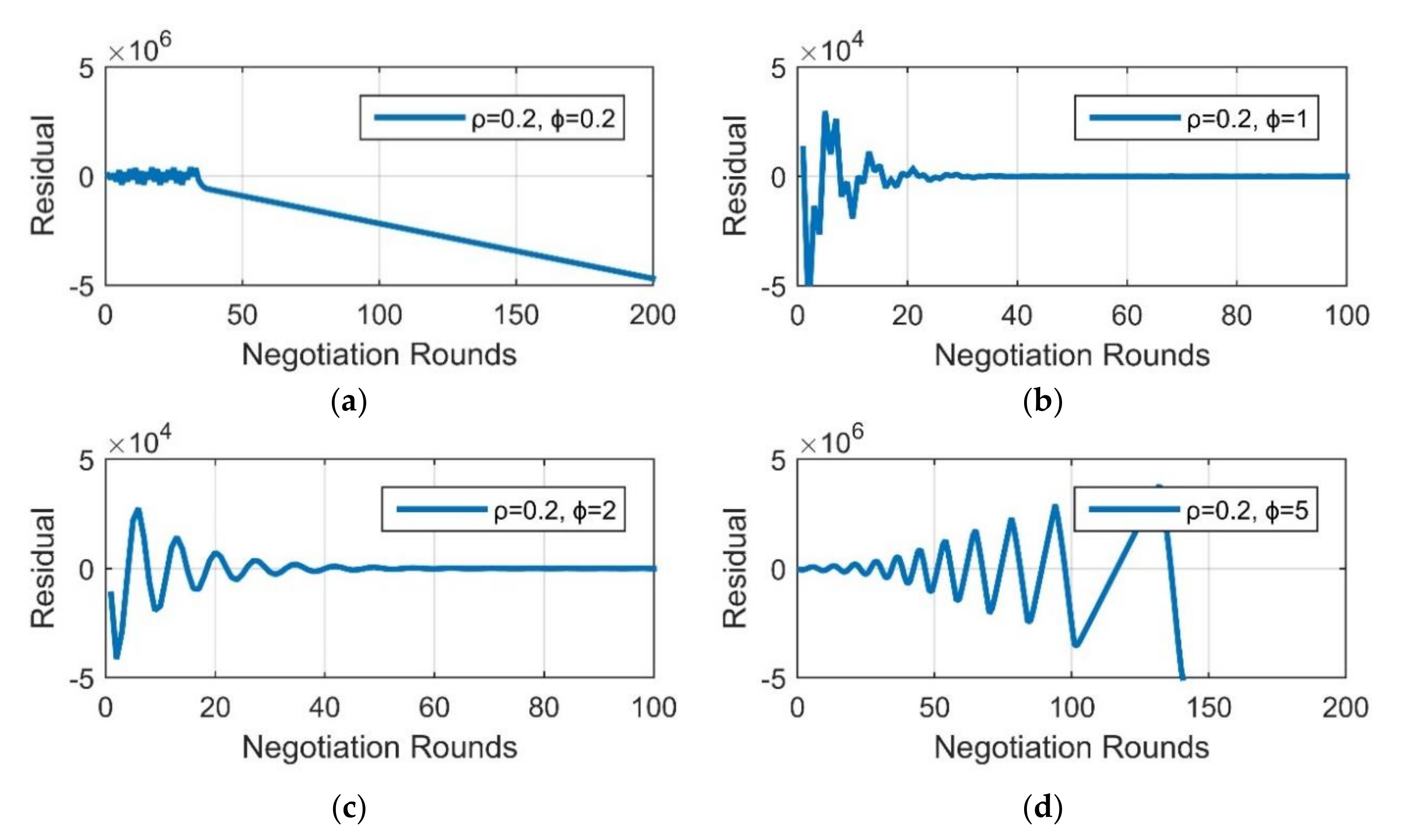
Figure 6 and Figure 7 show the selection of negotiation parameters, such as the penalty factor and the proximal factor , and their effects on the residual convergence. It is shown in Figure 6 that a larger penalty factor can accelerate the negotiation. However, the negotiation oscillates when the penalty factor exceeds a certain value. The introduction of a proximal term helps to improve the convergence of the negotiation process. Figure 7 shows simulation results for different values of the proximal factor when the penalty factor . It is observed that the proximal term enhances the possibility of convergence of the negotiation. However, an excessively large proximal factor results in divergence. After a number of simulations, an empirical conclusion was that it is relatively safe to choose a penalty factor that is smaller than 1 and a proximal factor that is 5–10 times larger than the penalty factor.
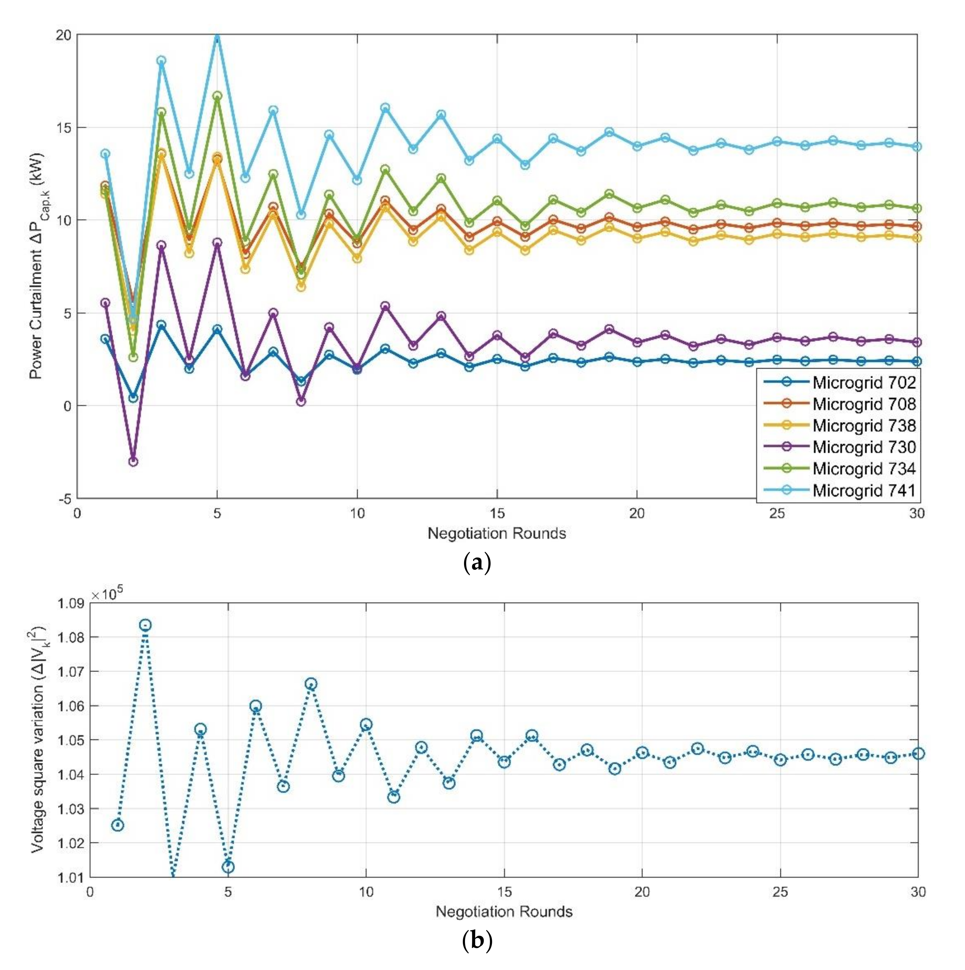
With the penalty factor, and the proximal factor,, the negotiation shows a fast convergence speed within 30 rounds. Figure 8 shows the update sequence of the microgrid power curtailment and the grid level-agent decisions in the negotiation process. The negotiation finally reaches an agreement that the VGI microgrids’ charging power curtailments are 2.44k W (node 702), 5.37 kW (node 730), 6.79 kW (node 708), 9.19 kW (node 734), 12.02 kW (node 738), and 14.16 kW (node 741) from their critical charging points. On the other hand, the grid-level agent adjusts its requirement from to .
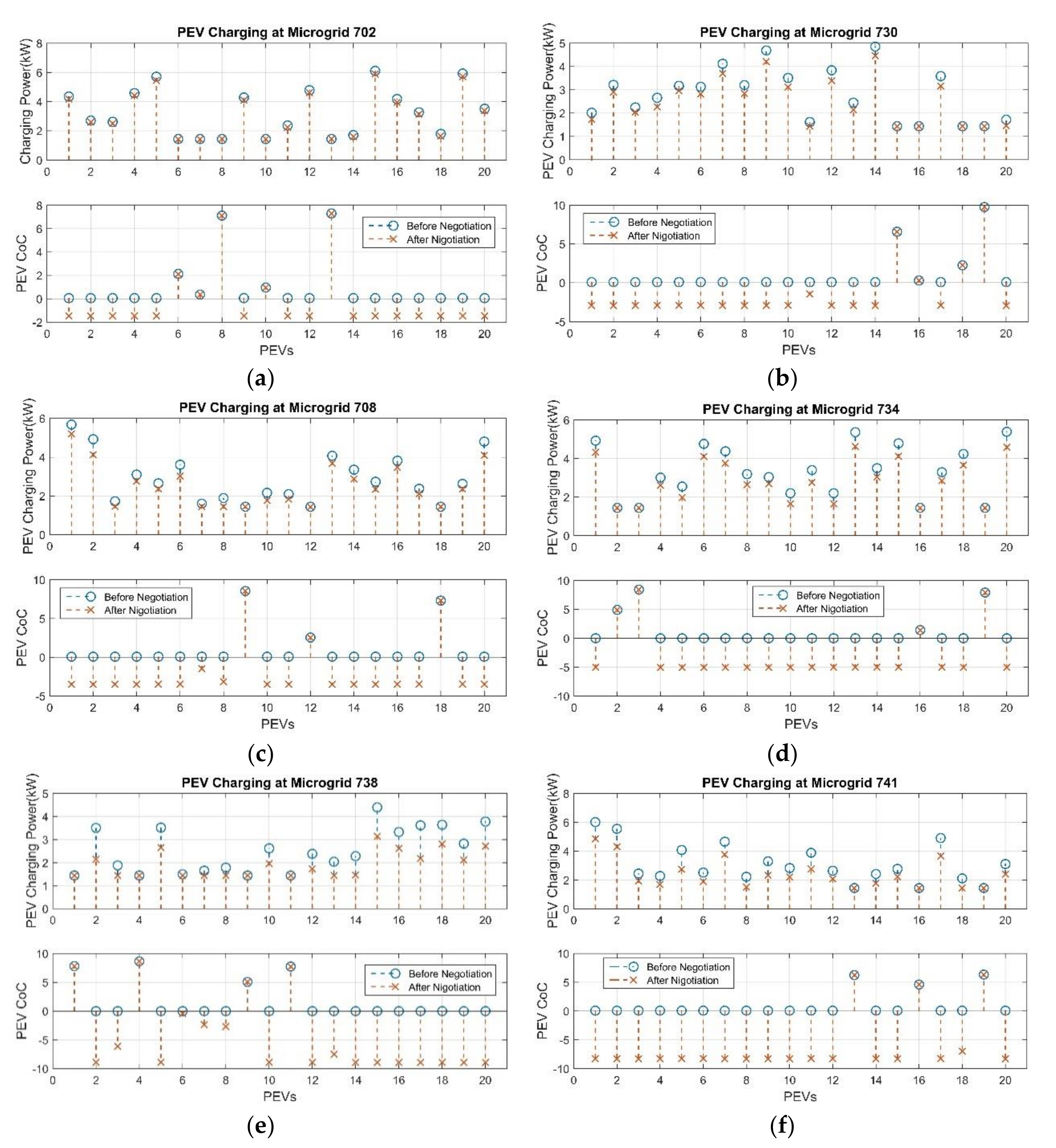
Figure 9 shows the PEV charging power and CoC comparison in each microgrid before and after the voltage compensation negotiation. The charging power of some PEVs is further reduced and results in the CoC value falling below zero. It was also found that VGI microgrids that are close to the voltage violation node curtail more power than the VGI microgrids that are far away from the voltage violation node. The reason is that the load variation near the voltage violation node has a larger effect on the voltage regulation.
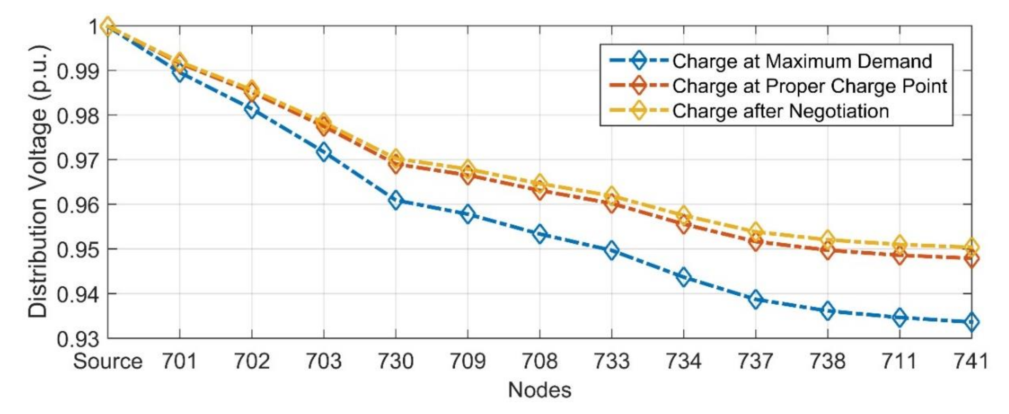
The simulation result testifies to the effectiveness of the distribution voltage compensation. Figure 10 shows the distribution voltage of each node along the distribution feeder line. The comparison is shown for the PEV charging scenarios: maximal power demand charging, charging at the VGI microgrid PEV critical charging power point, and charging after voltage compensation negotiation. The voltage compensation negotiation successfully raises the Node 741 voltage to around 0.9504 per unit.
6. Conclusions
This paper presents a distributed VGI control to realize voltage compensation service in a distribution network. The control scheme design is composed of two levels–the microgrid level and the distribution grid level. At the top level—the distribution grid level—an ADMM-based distributed voltage compensation negotiation among the multiple VGI microgrid agents and a grid-level agent is triggered when a voltage violation occurs. This distribution grid agent aims to maintain its distribution voltage level above the lowest threshold by sacrificing the microgrids’ power capacity. On the other side, each VGI microgrid agent wishes to minimize its power capacity curtailment to lower the impact to the PEV charging activities with in the VGI microgrid. Though having conflicting objectives, the negotiation coordinates the interests of all agents as an entity and finally reaches an agreement that all agents can accept. After determining the power capacity curtailment for each VGI microgrid, the CoC-based optimal microgrid VGI control algorithm aims to reasonably dispatch limited power to the charging PEVs and results in an average PEV charging satisfaction at the lower level, the VGI microgrid. We used a case study to simulate the application of the proposed algorithm in a VGI distribution grid to prove its effectiveness and advantages. First, the distributed algorithm allows each agent to pursue its own objective under the coordination of negotiation. This greatly reduces the computation burden of a single control unit compared to a centralized control design. Secondly, the two-level control design decouples the distribution grid-level control and single PEV charging control at the microgrid level. Each VGI microgrid becomes a relatively independent entity that controls the PEV charging activities within its range. This organization increases the scalability of the control scheme. However, the scenario presented in this paper applies certain simplifications. For example, distributed generation, like from renewable energy sources, was not considered. The possible utilization of a four-quadrant power inverter and large energy storage were also not in consideration. All these factors may provide both additional flexibility and uncertainty for the VGI control design in the distribution grid. We are going to consider improving the proposed control algorithm to better adapt to the factors above in future study.
Author Contributions
Conceptualization, C.C., Z.W. and B.C.; Methodology, C.C., Z.W. and B.C.; Software, C.C.; Validation, C.C.; Formal Analysis, C.C.; Investigation, C.C.; Resources, C.C.; Data curation, C.C.; Writing—original draft preparation, C.C.; Writing—review and editing, C.C. and B.C.; Visualization, C.C.; Supervision, B.C.; Project administration, B.C.; Funding acquisition, B.C. All authors have read and agreed to the published version of the manuscript.
Funding
This research received no external funding.
Conflicts of Interest
The authors declare no conflict of interest.
References
- Cao, C.; Cheng, M.; Chen, B. Optimal Scheduling of PEV Charging/Discharging in Microgrids with Combined Objectives. SGRE 2016, 7, 115–130. [Google Scholar] [CrossRef] [Green Version]
- Wang, L.; Cao, C.; Chen, B. Grid-Tied Single-Phase Bi-Directional PEV Charging/Discharging Control. SAE Int. J. Passeng. Cars Electron. 2016, 9, 275–285. [Google Scholar] [CrossRef] [Green Version]
- Wang, L.; Cao, C.; Chen, B. Model-Based Micro-Grid Modeling and Optimal PEV Charging Control. In Proceedings of the 2016 12th IEEE/ASME International Conference on Mechatronic and Embedded Systems and Applications (MESA), Auckland, New Zealand, 29–31 August 2016; pp. 1–6. [Google Scholar]
- Cao, C.; Wang, L.; Chen, B.; Harper, J.; Bohn, T.; Dobrzynski, D.; Hardy, K. Real-Time Modeling to Enable Hardware-in-the-Loop Simulation of Plug-In Electric Vehicle-Grid Interaction. In Proceedings of the 13th ASME/IEEE MESA, Cleveland, OH, USA, 6–9 August 2017. [Google Scholar]
- Cao, C.; Wang, L.; Chen, B. Mitigation of the Impact of High Plug-in Electric Vehicle Penetration on Residential Distribution Grid Using Smart Charging Strategies. Energies 2016, 9, 1024. [Google Scholar] [CrossRef] [Green Version]
- Nour, M.; Ramadan, H.; Ali, A.; Farkas, C. Impacts of Plug-in Electric Vehicles Charging on Low Voltage Distribution Network. In Proceedings of the 2018 International Conference on Innovative Trends in Computer Engineering (ITCE), Egypt, Aswan, 19–21 February 2018; pp. 357–362. [Google Scholar]
- Leou, R.; Su, C.; Lu, C. Stochastic Analyses of Electric Vehicle Charging Impacts on Distribution Network. IEEE Trans. Power Syst. 2014, 29, 1055–1063. [Google Scholar] [CrossRef]
- Cao, C.; Chen, B. Generalized Nash Equilibrium Problem Based Electric Vehicle Charging Management in Distribution Networks. Int. J. Energy Res. 2018, 42, 4584–4596. [Google Scholar] [CrossRef]
- Wang, L.; Chen, B. Distributed control for large-scale plug-in electric vehicle charging with a consensus algorithm. Int. J. Electr. Power Energy Syst. 2019, 109, 369–383. [Google Scholar] [CrossRef]
- Wang, L.; Chen, B. Dual-Level Consensus-Based Frequency Regulation Using Vehicle-to-Grid Service. Electr. Power Syst. Res. 2019, 167, 261–276. [Google Scholar] [CrossRef]
- Ranamuka, D.; Agalgaonkar, A.P.; Muttaqi, K.M. Dynamic Adjustment of OLTC Parameters Using Voltage Sensitivity While Utilizing DG for Volt/VAr Support. In Proceedings of the 2014 IEEE PES General Meeting, Gaylord National Resort & Convention Center On The Potomac, National Harbor, MD, USA, 27–31 July 2014; pp. 1–5. [Google Scholar]
- Baran, M.; Wu, F.F. Optimal Sizing of Capacitors Placed on a Radial Distribution System. IEEE Trans. Power Deliv. 1989, 4, 735–743. [Google Scholar] [CrossRef]
- Azzouz, M.A.; Shaaban, M.F.; El-Saadany, E.F. Real-Time Optimal Voltage Regulation for Distribution Networks Incorporating High Penetration of PEVs. IEEE Trans. Power Syst. 2015, 30, 3234–3245. [Google Scholar] [CrossRef]
- Wu, X.; Li, L.; Zou, J.; Zhang, G. EV-based voltage regulation in line distribution grid. In Proceedings of the 2016 IEEE International Instrumentation and Measurement Technology Conference Proceedings, Taipei, Taiwan, 23–26 May 2016; pp. 1–6. [Google Scholar]
- Kesler, M.; Kisacikoglu, M.C.; Tolbert, L.M. Vehicle-to-Grid Reactive Power Operation Using Plug-In Electric Vehicle Bidirectional Offboard Charger. IEEE Trans. Ind. Electron. 2014, 61, 6778–6784. [Google Scholar] [CrossRef]
- Kisacikoglu, M.C.; Ozpineci, B.; Tolbert, L.M. EV/PHEV Bidirectional Charger Assessment for V2G Reactive Power Operation. IEEE Trans. Power Electron. 2013, 28, 5717–5727. [Google Scholar] [CrossRef]
- Idaho National Laboratory. Advanced Vehicle Testing Activity. Available online: https://avt.inl.gov/content/charging-system-testing/vehicle-charging-system-testing (accessed on 15 June 2019).
- Boyd, S.; Parikh, N.; Chu, E.; Peleato, B.; Eckstein, J. Distributed Optimization and Statistical Learning via the Alternating Direction Method of Multipliers. Found. Trends Mach. Learn. 2011, 3, 1–122. [Google Scholar] [CrossRef]
- Cao, C.; Chen, B. The Hardware-in-the-Loop Simulation of Vehicle-Grid Integration in a Distribution Grid (Accepted). In Proceedings of the 2019 IEEE PES General Meeting, Atlanta, GA, USA, 4–8 August 2019. [Google Scholar]
- Hybrid – EV Committee SAE. SAE Electric Vehicle and Plug in Hybrid Electric Vehicle Conductive Charge Coupler - J1772; SAE International: Warrendale, PA, USA, 2017. [Google Scholar]
- Di Fazio, A.R.; Russo, M.; Valeri, S.; De Santis, M. Sensitivity-Based Model of Low Voltage Distribution Systems with Distributed Energy Resources. Energies 2016, 9, 801. [Google Scholar] [CrossRef]
- IEEE Power & Energy Society. IEEE PES AMPS DSAS Test Feeder Working Group/resources. Available online: http://0-sites-ieee-org.brum.beds.ac.uk/pes-testfeeders/resources/ (accessed on 20 April 2019).
- Office of Energy Efficiency & Renewable Energy. Commercial and Residential Hourly Load Profiles for all TMY3 Locations in the United States. Available online: https://openei.org/datasets/dataset/commercial-and-residential-hourly-load-profiles-for-all-tmy3-locations-in-the-united-states (accessed on 15 February 2019).
Figure 1.
The physical components and control architecture of a distribution-level VGI system.

Figure 2.
The determination of PEV charging power capacity in microgrids.

Figure 3.
The adjacent buses in a distribution feeder branch.

Figure 4.
The development and message flow of the distributed voltage compensation negotiation and VGI microgrid control.
Figure 4.
The development and message flow of the distributed voltage compensation negotiation and VGI microgrid control.

Figure 5.
The distribution grid topology in the use case study.

Figure 6.
The negotiation process with different values of penalty factor . Sub-figure (a) shows a very slow convergence rate with , Sub-figure (b,c) show faster convergence within the range , but (c) demonstrates an even better convergence rate. Sub-figure (d) show negotiation does not converge when increases and reaches 0.2.

Figure 7.
The negotiation process with different values of proximal factor . Adding proper proximal factor can increase the robustness of the negotiation. Sub-figure (a) shows adding a small Proximal Factor,, does not help negotiation with a large penalty factor to converge. Sub-figure (b,c) show that if the proximal factor,, is within proper range, the robustness of negotiation increases. (d) demonstrates an exceedingly large proximal factor,, breaks the negotiation convergence.

Figure 8.
Updates of microgrid power curtailment and the voltage square variation during negotiation. (a) shows the power capacity curtailment evolvements of different VGI Microgrids along the distribution line during the negotiation process. (b) shows the voltage square difference caused by change of VGI Microgrids power capacity change during the negotiation process.

Figure 9.
The negotiation effects on PEV charging in the microgrids. (a–f) show PEV Charging power and CoC value comparison before and after the negotiation process in different VGI Microgrids along the distribution lines.
Figure 9.
The negotiation effects on PEV charging in the microgrids. (a–f) show PEV Charging power and CoC value comparison before and after the negotiation process in different VGI Microgrids along the distribution lines.

Figure 10.
Voltage along the distribution feeder branch in different charging scenarios at 10:00 am.
Figure 10.
Voltage along the distribution feeder branch in different charging scenarios at 10:00 am.


Table 1.
The building and number of EVSEs in microgrids.
| MG | Building Types | EVSE Units |
|---|---|---|
| 701 | Medium office, Strip mall | 0 |
| 702 | Supermarket | 20 |
| 703 | Small restaurant, Retail store | 0 |
| 730 | Large office | 20 |
| 709 | Supermarket | 0 |
| 708 | Supermarket, Warehouse | 20 |
| 733 | Strip mall, Retail store | 0 |
| 734 | Small and medium office | 20 |
| 737 | Restaurant, Retail store | 0 |
| 738 | Multiple small offices | 20 |
| 711 | Primary school, small offices | 0 |
| 741 | Warehouse | 20 |
Table 2.
PEV battery and charging parameters [17].
Table 2.
PEV battery and charging parameters [17].
| PEV Type | Battery Capacity | Maximum Charge Rate | Minimum Charge Rate |
|---|---|---|---|
| Nissan Leaf 2013 | 66.2 Ah | 6.6 kW | 1.44 kW |
| BMW i3 2014 | 60.0 Ah | 7.2 kW | 1.44 kW |
| Chevy Volt 2013 | 45.0 Ah | 3.1 kW | 1.44 kW |
Table 3.
Uncontrollable load and PEV charging power demand at 10:00 am in each node along the distribution feeder branch.
Table 3.
Uncontrollable load and PEV charging power demand at 10:00 am in each node along the distribution feeder branch.
| Microgrid | Building Demand (kW) | MG PEV Charging Demand (kW) | MG Critical Charging Power Point (kW) |
|---|---|---|---|
| 701 | 93.32 | 0 | 0 |
| 702 | 129.6 | 112.8 | 65.1 |
| 703 | 97.76 | 0 | 0 |
| 730 | 74.36 | 119.2 | 66.0 |
| 709 | 129.6 | 0 | 0 |
| 708 | 66.35 | 113.4 | 55.8 |
| 733 | 62.22 | 0 | 0 |
| 734 | 101.4 | 109.3 | 50.5 |
| 737 | 96.87 | 0 | 0 |
| 738 | 99.15 | 117.5 | 57.5 |
| 711 | 84.87 | 0 | 0 |
| 741 | 69.43 | 123.3 | 62.0 |
© 2020 by the authors. Licensee MDPI, Basel, Switzerland. This article is an open access article distributed under the terms and conditions of the Creative Commons Attribution (CC BY) license (http://creativecommons.org/licenses/by/4.0/).
Share and Cite
MDPI and ACS Style
Cao, C.; Wu, Z.; Chen, B. Electric Vehicle–Grid Integration with Voltage Regulation in Radial Distribution Networks. Energies 2020, 13, 1802. https://0-doi-org.brum.beds.ac.uk/10.3390/en13071802
AMA Style
Cao C, Wu Z, Chen B. Electric Vehicle–Grid Integration with Voltage Regulation in Radial Distribution Networks. Energies. 2020; 13(7):1802. https://0-doi-org.brum.beds.ac.uk/10.3390/en13071802
Chicago/Turabian StyleCao, Chong, Zhouquan Wu, and Bo Chen. 2020. "Electric Vehicle–Grid Integration with Voltage Regulation in Radial Distribution Networks" Energies 13, no. 7: 1802. https://0-doi-org.brum.beds.ac.uk/10.3390/en13071802
Note that from the first issue of 2016, this journal uses article numbers instead of page numbers. See further details here.