Wave Power Absorption by Arrays of Wave Energy Converters in Front of a Vertical Breakwater: A Theoretical Study


Laboratory for Floating Structures and Mooring Systems, Division of Marine Structures, School of Naval Architecture and Marine Engineering, National Technical University of Athens, 9 Heroon Polytechniou Avenue, GR 157-73 Athens, Greece
*
Author to whom correspondence should be addressed.
Energies 2020, 13(8), 1985; https://0-doi-org.brum.beds.ac.uk/10.3390/en13081985
Submission received: 13 March 2020
/
Revised: 6 April 2020
/
Accepted: 13 April 2020
/
Published: 17 April 2020
(This article belongs to the Section A3: Wind, Wave and Tidal Energy)
Abstract
:The present paper deals with the theoretical evaluation of the efficiency of an array of cylindrical Wave Energy Converters (WECs) having a vertical symmetry axis and placed in front of a reflecting vertical breakwater. Linear potential theory is assumed, and the associated diffraction and motion radiation problems are solved in the frequency domain. Axisymmetric eigenfunction expansions of the velocity potential are introduced into properly defined ring-shaped fluid regions surrounding each body of the array. The potential solutions are matched at the boundaries of adjacent fluid regions by enforcing continuity of the hydrodynamic pressures and redial velocities. A theoretical model for the evaluation of the WECs’ performance is developed. The model properly accounts for the effect of the breakwater on each body’s hydrodynamic characteristics and the coupling between the bodies’ motions and the power take-off mechanism. Numerical results are presented and discussed in terms of the expected power absorption. The results show how the efficiency of the array is affected by (a) the distance between the devices and the wall, (b) the shape of the WEC array configuration, as well as (c) the angle of the incoming incident wave.
1. Introduction
The concept of harvesting energy from the ocean is not a recent idea. Several hundreds of patents related to wave energy conversion have been in existence since the late 20th century [1,2,3]. Especially, ocean wave energy, as a choice of alternative form of energy supply, is attractive since it has the second largest potential among all ocean renewable energy sources [4]. However, since ocean energy technologies face several bottlenecks concerning survivability aspects, lack of grid availability and environmental and administrative issues [5], the wave energy sector is focusing on Wave Energy Converter (WEC) types either isolated or placed in an array for near-shore installation and operation [6,7]. The installation of a WEC system into other maritime structures such as a breakwater or a harbor, so as to supply wave power to the shore, can increase the system’s efficiency by taking advantage of the scattered and the reflected waves from the vertical wall reducing in parallel the intensity of wave action on the shore [8,9].
Looking towards the multiple abilities provided by the WEC–maritime structure system, numerous different designs of such integrated systems have been presented in the literature. In [10,11] the performance characteristics of an array of five wave energy heaving converters, placed in front of a reflecting vertical breakwater, have been theoretically and experimentally investigated, whereas in [12] the resonances of a freely floating half immersed cylinder in front of a vertical rigid wall have been studied. A single truncated cylinder and an oscillating water column device (OWC), placed in front of a breakwater, have been studied in [13,14,15,16,17], respectively, concerning the solution of the corresponding wave diffraction and motion and pressure radiation problems. In [18] the efficiency of a single heaving WEC placed in front of a vertical wall has been examined under the action of regular and irregular waves for different WEC geometries and distances from the wall. In these works, a completely reflecting boundary of infinite extent is assumed by the use of the method of images. The method of images is used to describe the fluid around the examined body in front of a breakwater. This method has been applied in the past to tackle the diffraction and radiation problems of a single or array of cylinders in channels [19,20,21]. Moreover, the method’s results have been validated against experimental and numerical investigations of other research tackling the same problem using other methodologies [22,23]. In [24] the effect of a finite length breakwater on the hydrodynamics of an array of cylindrical heaving WECs has been studied. Nevertheless, in these investigations the breakwater is being considered as an elliptical cylinder with zero semi-minor axes. Recently, in [25] the absorption ability of an array of semi-immersed, oblate spheroidal heaving WECs placed in front of a vertical wall has been examined.
Alternatively, to the existence of a WEC array in front of a vertical wall, several studies have been presented in the literature concerning converters integrated into a breakwater. More specifically, in [26,27] the performance of a WEC integrated into a breakwater was numerically and experimentally investigated, whereas in [28,29,30] numerical analysis and experimental investigation into OWC integrated at a flat breakwater have been presented. Furthermore, in [31] an array of OWCs attached to a floating pontoon has been examined, and the efficiency of the devices was numerically investigated. Other noteworthy studies on the subject have been presented [32,33,34]. Despite the advantages that WECs integrated into a breakwater have, in terms of installation, mooring and maintenance issues, such converters seem to be lessened, as far as their wave energy efficiency is concerned, compared to WECs placed in front of a vertical wall. In this case, the possibility to have them installed at different distances from the breakwater in dependence from the prevailing sea conditions at the installation locations represents a main advantage towards optimizing their efficiency.
This paper deals with the efficiency of an array of vertical cylindrical WEC devices placed in front of a breakwater, absorbing energy moving in heave. Each WEC is assumed to be equipped with a linear Power Takeoff (PTO) mechanism, actuated by its heave motion. Several distances between the cylindrical converters and the vertical wall are examined, along with different array configurations (i.e., cylinders in parallel; perpendicular and square arrangements in front of the wall) and wave heading angles in order to comparatively assess their wave power absorption characteristics towards their optimization. The presented theoretical model takes exactly into account the hydrodynamic interaction phenomena between the WECs and the reflecting fluid flow in front of the vertical wall, and numerical results are presented in the frequency domain. This study extends the analysis presented in [35], where by applying the method of images (for the effect of the vertical wall) and the method of ‘matched’ eigenfunction expansions (for the velocity potential in the fluid domain surrounding each device of the array), the diffraction and motion radiation characteristics of arrays of vertical axisymmetric floaters of arbitrary geometry placed in front of a vertical wall have been evaluated. Here, the fundamental hydrodynamic properties of each examined floater in front of the breakwater, as they have been derived in [35], are fed into the equations of motions of the WEC array to derive the displacement of each converter and, as a result, the absorbed wave power by the array.
This work is organized as follows: Section 2 formulates the solution of the corresponding diffraction and motion radiation problems; Section 3 is devoted to the solution of the motion equation system as well to the determination of the absorbed wave power by the converters and the evaluation of the q factor of the WEC wall system; Section 4 provides and discusses the numerical results obtained via the semi-analytical methodology; and finally the conclusions are drawn in Section 5.
2. Hydrodynamic Formulation
2.1. The Boundary Value Problem
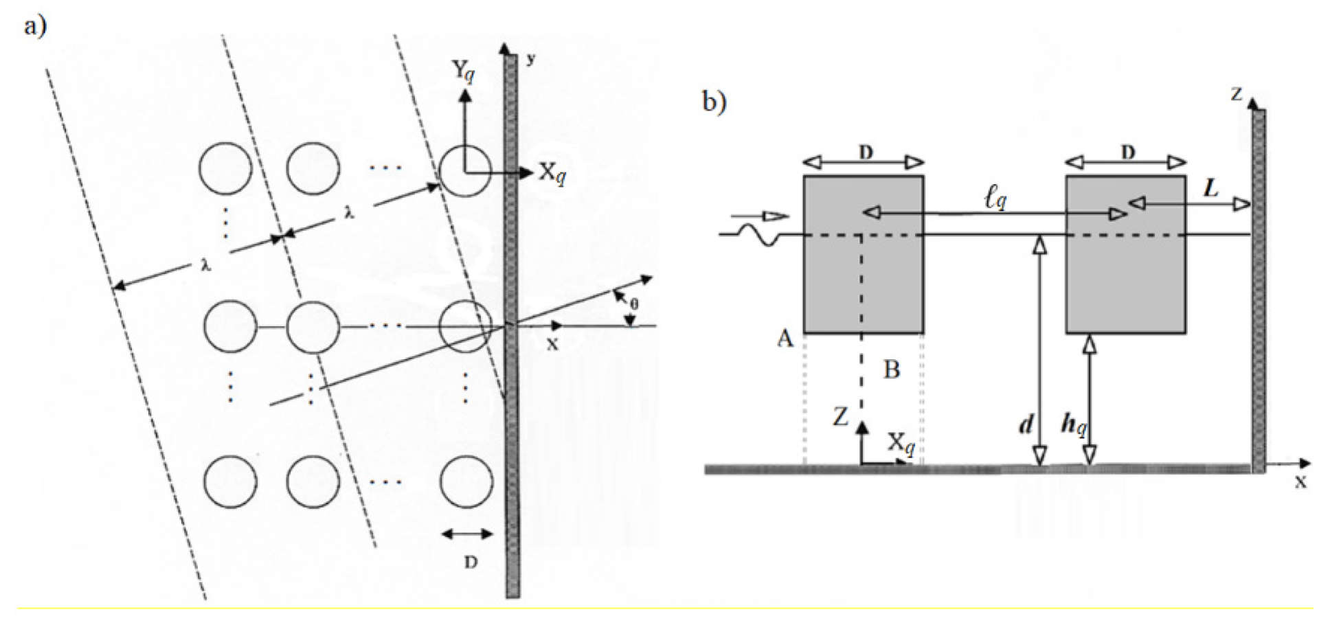
An array of N vertical cylindrical WECs placed in front of a vertical breakwater is considered. The wall and the cylinders extend beyond the undisturbed free surface, while the rigid wall is fixed on the sea bottom. The water depth is denoted by d and it is constant assuming that the sea bottom is flat and horizontal. The distance between the bottom of the k converter, i.e., k = 1,…, N, and the flat bottom is denoted by hk, whereas the diameter of each converter is denoted by D. The converters are exposed to the action of a plane incident wave train of frequency ω and amplitude A propagating at an angle θ with respect to the positive x-axis. A global, right-handed Cartesian coordinate system O-xyz is introduced with origin O located at the bottom of the breakwater with its vertical axis Oz directed upwards. Moreover, for each of the converters in the array, a local cylindrical coordinate system (), q = 1,2,…, N is defined with origin at the intersection (), i.e., and , of the sea bottom with the vertical axis of symmetry of each body. The distance between the wall and the center of the closest to the wall converter is denoted by L, whereas the distance between the centers of adjacent converters of the array is denoted by ℓq, k = 1,2,…, N (see Figure 1).
The diffraction and the motion radiation problems are considered within the linear potential theory assuming an inviscid, incompressible liquid and irrotational flow. The fluid flow around each converter q, q = 1,…,2N, (including the N number of the initial WECs of the array and the N number of their image converters [35]) can be described in a local cylindrical coordinate system (), q = 1,2,…, N, by the potential function, and expressed, on the basis of linear modeling, as a superposition of incident , scattered, and radiated wave fields, , as follows:
Here, denotes the potential of the wave field around the q body induced by the forced oscillation of converter p in the j-th direction, the remaining ones considered restrained, whereas is the diffraction potential equal to .
The fluid domain is denoted by Ω and extends to infinity. The volume of the converters is excluded from Ω. The undisturbed free surface is denoted by SF, which also extends to infinity. Similarly, the cross sections of all the converters on the undisturbed free surface are excluded from SF. The mean wetted surface of converter q, q = 1,…, 2N, is denoted by Sq. The boundary value problem can be composed by the following set of equations:
Here denotes the derivative in the direction of the outward unit normal vector to the mean wetted surface Sp of converter p; is Kronecker’s symbol; denotes the amplitude of the linear translation and rotation motions of floater q; and are the generalized normal components defined by
where is the position vector of a point on Sq with respect to converter q’s forced oscillations center expressed in the local coordinate system ().
Finally, a radiation condition must be imposed which states that propagating disturbances must be outgoing. Equation (2) is the Laplace equation. Equation (3) is the combined linear kinematic and dynamic boundary condition on the free surface. Equation (4) is the zero-velocity condition on the flat sea bottom. Equations (5) and (6) are the kinematic conditions on the wetted surface of all the converters.
2.2. Determination of the Velocity Potentials
The diffraction and the motion radiation potential around converter q, expressed in its own cylindrical coordinate system, can be expressed as follows:
The complex functions and represent the principal unknowns of the problem. They can be determined in the way proposed by [35,36,37], by combining the single-body hydrodynamic characteristics through the physical idea of multiple scattering to account for interference effects and the method of images to simulate the effect of the breakwater behind the array. According to the method of images, the problem under investigation (i.e., N number of WECs placed in front of a vertical wall) is equivalent to the one of an array of 2N WECs consisting of N initial converters and their N image virtual bodies, with respect to the breakwater. The 2N WECs are exposed to the action of surface waves without the presence of the breakwater. A more detailed description of the method is presented in [10,35]. As far as the applied method of multiple scatterings is concerned, exact representations of the total wave field around each converter of the array can be obtained by superposing the incident wave potential and various orders of propagating and evanescent wave modes that are scattered and radiated by the bodies of the array. The advantage of this method is the low storage requirements in computer applications since the boundary conditions on each converter are satisfied successively without retaining the partial wave amplitudes simultaneously around all the bodies of the array. This method, applied to arrays of an arbitrary number of bodies, has been described in detail in [36,37,38].
Having simulated the effect of the breakwater onto the WEC array and determined the interaction phenomena between the bodies of the array, the unknown functions involved in Equations (8) and (9) are established through the method of matched axisymmetric eigenfunctions expansions. According to the matching technique, the velocity and the pressure fields should be continuous across the common boundaries of the coaxial ring-shaped fluid regions, denoted by A and B (see Figure 1), which the flow field around each converter has been subdivided in. In particular, the velocity potential around each converter of the array can be written as different series expansions in each fluid regions, i.e., . These series representations are solutions of the Laplace equation (see Equation (2)) and satisfy the kinematic boundary condition at the walls of the float (see Equations (5) and (6)), the linearized condition at the free surface (see Equation (3)), the kinematic condition at the sea bed (see Equation (4)), and the radiation condition at infinity. More specifically, the following relations should be satisfied:
Here are the velocity potentials of converter q of the array at the A and B fluid regions, respectively.
After determining the unknown coefficients and , the velocity potential of converter q at each fluid region A and B can be established. Herein, it should be noted that analytical representations of the velocity potentials around an arbitrary shape WEC can be found in [35]; thus, no further elaboration is made in this article.
3. Efficiency of a WEC Array
3.1. Motion Equation System
The motion system of an array of N independently floating vertical cylindrical bodies placed in front of a vertical breakwater in the frequency domain can be written as follows:
where is the six-degree displacement vector of the p floater of the array; is the mass matrix of the q floater; and are the frequency-dependent hydrodynamic mass and damping matrix, respectively, of floater q in the k-th direction due to the forced oscillation of floater p in the j-the direction (see Equation (19) in [35]); is the total stiffness matrix, consisting of the converter’s hydrostatic restoring stiffness and the stiffness of a linear mooring (i.e., assuming a WEC spring system); represents the exciting wave force on floater q floater in the k-th direction (see Equation (17) in [35]); and is Kronecker’s symbol.
In the present contribution, the WECs in the array are assumed to move only in the heave direction (i.e., k = j = 3). Furthermore, the PTO mechanism of converter q is modelled as a linear damping system with damping coefficient actuated from the heave motion of the corresponding converter. Thus, Equation (12) can be rewritten for an array of N heaving WECs in front of a breakwater as follows:
3.2. Absorbed Wave Power—q Factor
In regular incident waves, the power extracted at each wave frequency by each converter of the array is
Whereas, the extracted power by the whole WEC array is derived by
In order to examine the positive or negative effect of the breakwater on the efficiency of the WECs, the q factor as introduced in [38] is applied. More specifically, the factor equals the ratio of the total extracted power by the whole WEC array to the extracted power by N isolated WECs (i.e., without taking into consideration the hydrodynamic interactions) for a given wave frequency. Thus,
Here, corresponds to the extracted power by a similar WEC in isolation conditions, and N is the number of the converters in the array.
If there were no interaction phenomena between the converters and the breakwater then the extracted power by each converter would be the same as if it were in isolation, thus the q factor would be equal to unity for every examined wave frequency. However, as presented and discussed in the next Section 4, the interaction phenomena between the bodies of the array and the vertical wall have a major impact on the q factor and consequently on the efficiency of the array.
4. Numerical Results
In the present section, three different array configurations of vertical cylindrical WECs are examined. The WECs are placed in front of a vertical breakwater in (a) parallel to the wall arrangement, C1; (b) in a rectangular arrangement in front of the wall, C2; and (c) perpendicular to the wall arrangement, C3; (see Figure 2). The same arrangements were examined also in [35] concerning the effect of the breakwater on the hydrodynamic characteristics of the WECs.
The incoming waves are assumed to propagate at indicative angles of θ = 0, 45 and 60° with respect to the x-axis (see Figure 1). The examined point absorbers have a radius D = 2 m; a draught (d−h)/D = 1; at a water depth d/D = 5 (see Figure 1). The distance between the center of the closest to the wall converter and the breakwater is L, whereas the inter-body spacing for adjacent WECs is lb = 10D (in C2 array, see Figure 2, the distance from the 4th to the 5th device and from the 1st to the 2nd device is 1.732lb). The mass of each examined WEC equals 6440 kg, whereas all the WECs are assumed to have the same PTO characteristics, i.e.,, equal to the heave radiation damping of a similar isolated WEC at its heave natural frequency [39]. According to the presented analysis, the heave natural frequency of an isolated WEC has been calculated equal to 1.95 rad/s; thus, the heave radiation damping of the converter equals 446.9 kg/s (i.e., kg/s). Initially, additional stiffness due to moorings is not considered.
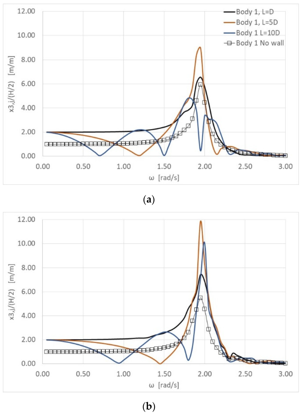
In the next figures, the effects of the breakwater on the WECs’ heave responses are presented for various examined distances between the devices and the vertical wall, i.e., L = D, 5D and 10D. In Figure 3 and Figure 4 the modulus of the heave responses of the first and the third WEC of the C1 arrangement (i.e., parallel to the wall, see Figure 2), normalized by A, are presented for the previously defined wave heading angles and distances. The results are compared with the corresponding heave responses of the same WECs of the array without, however, the presence of the vertical wall. In Figure 5, Figure 6, Figure 7 and Figure 8 the corresponding modulus of the heave responses of the 1st and the 3rd WEC devices are presented for the C2 and C3 arrangements (i.e., rectangular and perpendicular, see Figure 2), respectively. In Appendix A, the corresponding modulus and phase of the heave responses of the 1st WEC device are also presented in a tubular form, for indicative values of wave frequencies, to allow more accurate comparisons to be made with other numerical estimates.
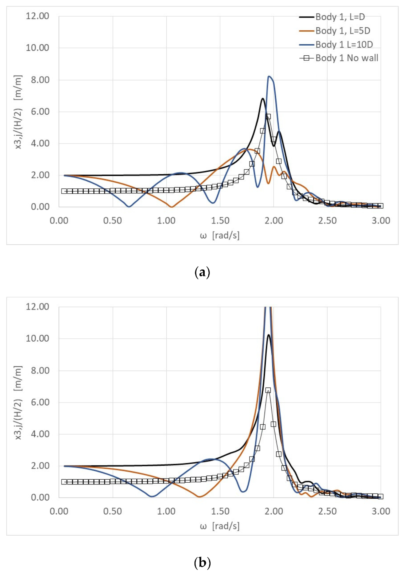
It can be seen in Figure 3 that the heave displacement of the 1st converter is almost two times larger than the heave displacement of the same converter of the array, without the presence of the breakwater. This is occurring for ω tending to zero, at all the examined distances from the wall and the wave heading angles. This was also the case for the heave exciting wave forces and the heave damping coefficient of the same converter of the array as presented in [35] (see Figures 9, 10, 16 and 18 in [35]). Following the conclusions of [24], the duplication of the heave displacement for wave frequencies tending to zero can be traced back to the fact that in the applied image method a fully wave-reflecting wall of infinite length has been assumed. Furthermore, it can be seen from Figure 3 that for the distance examined closer to the wall (i.e., L = D), the heave displacement of the converter does not attain any minimizations for wave frequencies lower than 2 rad/s. The same behavior is also depicted for the array without the presence of the vertical wall. However, in the WEC breakwater case and for the distances L = 5D, 10D, the WEC’s heave displacement attain minimizations for ω < 2 rad/s. These minimizations are shifted to smaller wave frequencies as the distance between the converters and the wall increases. Moreover, the wave frequencies where these minimizations appear are also affected by the angle of the incoming wave. More specifically, for larger wave heading angles these resonances are shifted to higher wave frequencies. Thus, for the highest examined wave angle, i.e., 60°, and for the largest examined distance from the wall, i.e., L = 10D, the minimization of the heave displacement is attained at ω = 1.20 rad/s. On the other hand, for a zero-wave angle and for the same distance L = 10D, the heave displacement minimizes three times (i.e., at ω = 0.7, 1.5 and 1.9 rad/s). The zeroing of the heave displacement is due to the interaction phenomena between the converters and the breakwater, and in particular it appears when the distance between the examined converter and its image device (i.e., derived from the image method) equals a multiple value of the half wave length [40]. Furthermore, it can be seen in Figure 3 that the heave displacements resonate in the neighborhood of the WEC’s heave natural frequency, i.e., at ω = 1.95 rad/s, regardless the examined wave heading angles and distances between the WECs and the vertical wall. This is also evident for the L = 10D and θ = 0° cases, where the WEC’s natural frequency is very close to the minimization frequency of the WEC’s heave displacement.
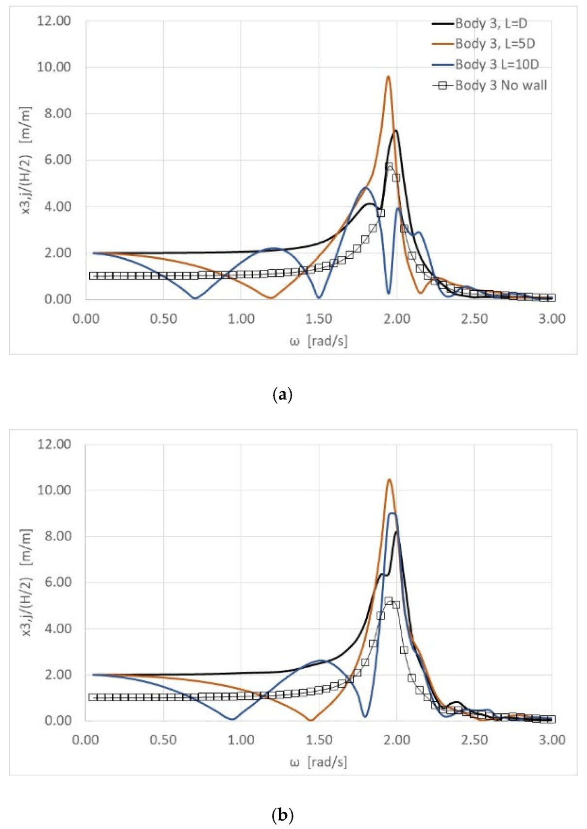
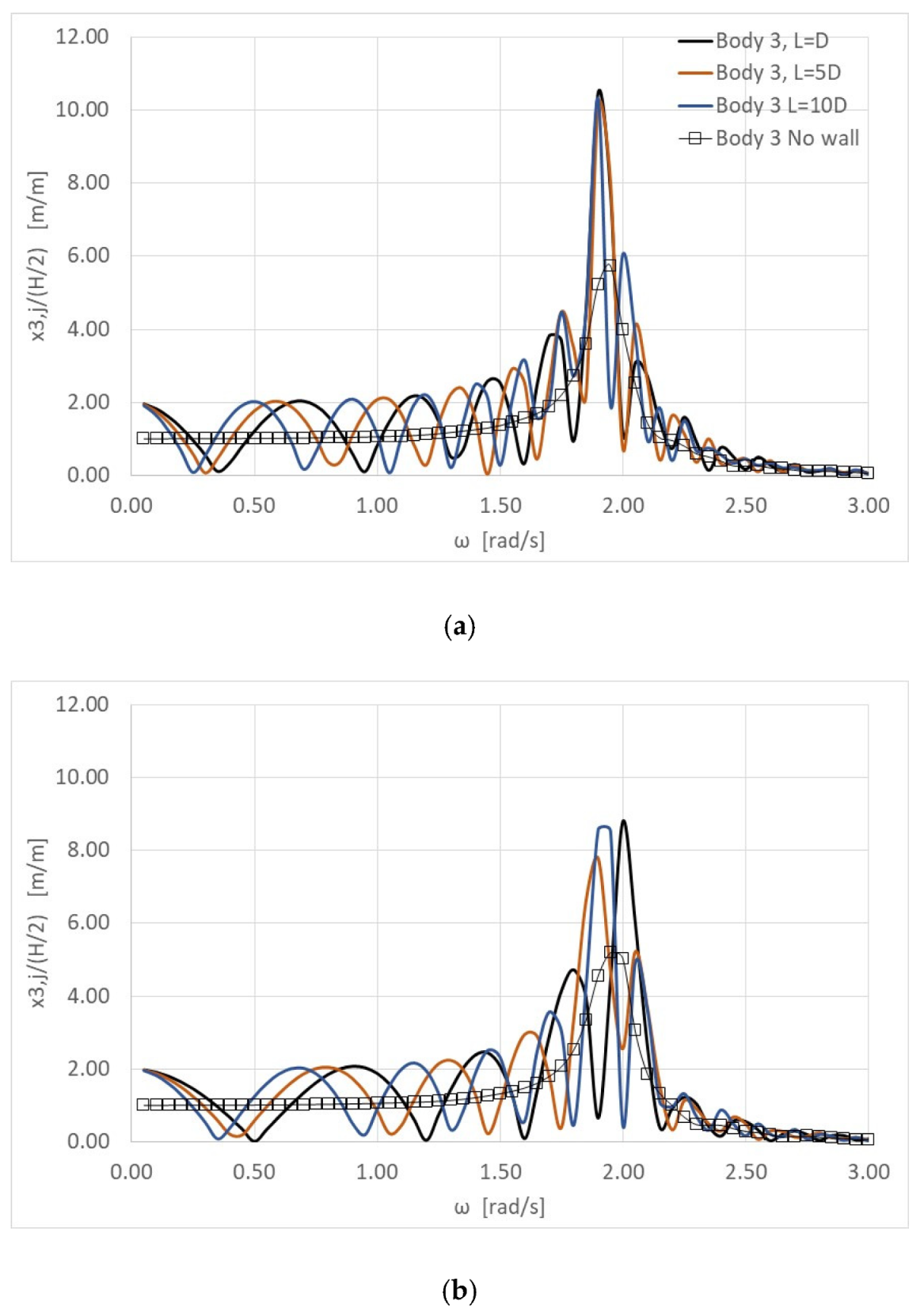
In Figure 4 the heave displacement of the 3rd converter (see Figure 2) is presented for the previous described distances between the WECs and the vertical wall and the angles of the incoming wave. The same conclusions as in Figure 3 can be drawn here, concerning the duplication of the heave displacement at wave frequencies tending to zero and the minimization of the heave motions at specific wave frequencies, relevant to the distance L and the angle θ. It is also worthwhile to mention in Figure 4 that in the L = D case, the heave displacement of the 3rd converter appears at a local maximum at ω = 1.80 rad/s. This additional peak is due to the interaction phenomena between the WECs of the array, and it is evident at every examined wave heading angles.
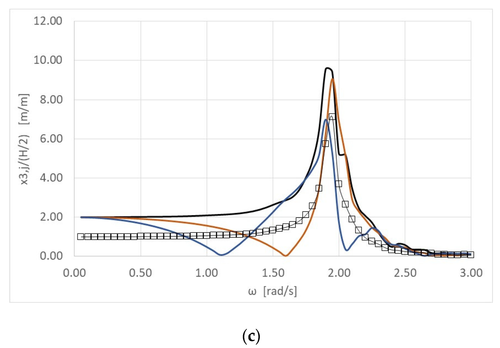
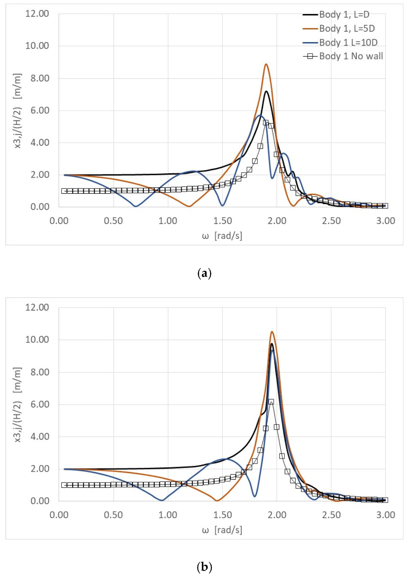
Figure 5, Figure 6, Figure 7 and Figure 8 depict the effect that the type of the WEC arrangement has (i.e., rectangular and perpendicular, see Figure 2) on the WECs heave displacement. Here, the previous WEC wall distance cases, i.e., L = D, 5D, 10D, and wave heading angles, i.e., θ = 0, 45 and 60°, are examined. In these figures, results corresponding to the same WEC array without the presence of the vertical wall are also included. It can be seen from the figures that the WECs’ heave responses exhibit a similar behavior as in the previous examined C1 configuration, concerning their duplication at ω tending to zero, and their maximization around the WEC’s heave natural frequency. Furthermore, comparing the heave motions of the 1st WEC (i.e., converter closer to the wall) at the three arrangements, C1, C2, C3, for zero wave angle (i.e., Figure 3a, Figure 5a, Figure 7) it can be seen that the wave frequencies where the converter’s displacement attains a minimum value are the same for the parallel and perpendicular arrangements. As far as the rectangular arrangement is concerned, the WEC’s heave displacement minimizes at lower wave frequencies compared to their counterparts for the C1, C3 arrangements. For the 3rd WEC of the three examined arrangements, for a zero-wave angle (see Figure 4a, Figure 6a, Figure 8a) the values of the WEC’s heave motions oscillate around the corresponding values of the same converter of the array, without the presence of the breakwater, attaining additional minimizations. These oscillations become more pronounced for the rectangular and for the perpendicular to the wall arrangement and are due to the scattered and reflected waves that seem to strongly affect the wave field around these arrangements with respect to the incident wave direction. As far as the examined wave heading angles is concerned, it can be seen from Figure 5b,c and Figure 7b,c that the heave responses of the 1st WEC for the C2 and C3 arrangement follow a similar variation pattern as in the C1 arrangement. More specifically, the resonant frequencies are shifted to higher values as the wave angle increases. As a result, the number of the WEC heave-motion-minimizations, for the L = 10D case, decrease as the wave angle increases (see Figure 5 and Figure 7). The same conclusion can be drawn when the heave response of the 3rd WEC is examined. However, due to the WECs position in the arrangement, with respect to the incoming wave, this reduction in the number of frequencies where the heave motion zeroes can be also obtained for the middle distance case (i.e., L = 5D).
Compared to the no-wall WEC array, the results from Figure 3, Figure 4, Figure 5, Figure 6, Figure 7 and Figure 8 illustrate that the presence of the wall has a significant impact on the WECs’ heave responses, at every examined distance from the wall and wave angle, in almost the entire wave frequency range. More specifically, for ω < 2.5 rad/s, the WECs’ heave motions exhibit either higher values than the corresponding ones from the no-wall case (i.e., Cl arrangement) or values that are oscillating around those of the no-wall case (i.e., C2, C3 arrangements). On the other hand, the effect of the breakwater becomes less pronounced for ω > 2.5 rad/s, since the WEC wall cases and the no-wall case appear as comparable results.
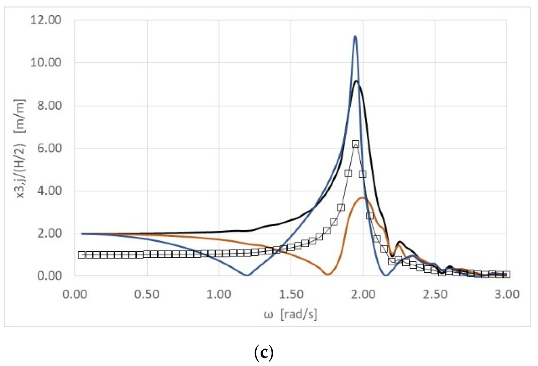
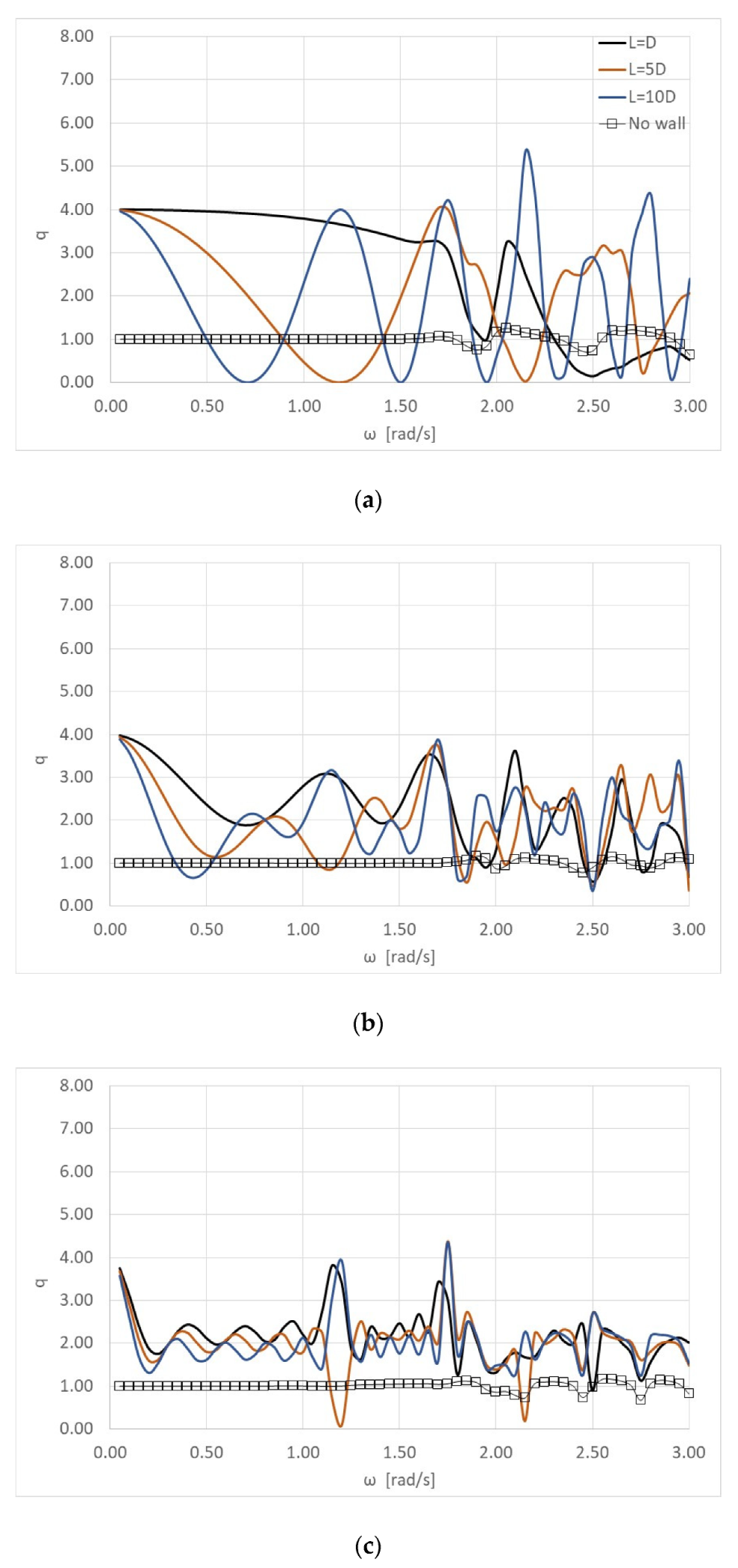
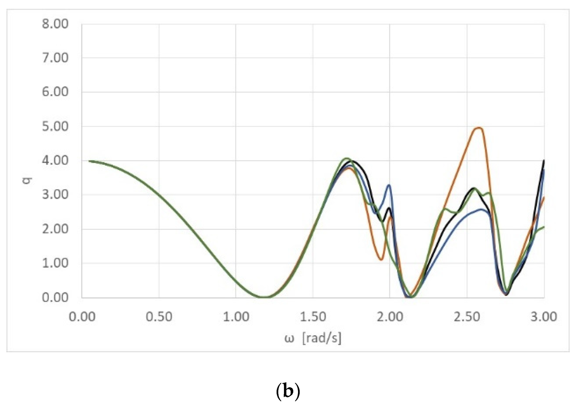
In order to examine the effect of the vertical wall on the efficiency of the WEC arrays, the q factor (see Equation (17)) is plotted in the next figures. Starting with the efficiency of each WEC array arrangement (i.e., C1, C2, C3), Figure 9 depicts the q factor for the three distance configurations (i.e., L = D, 5D, 10D) and for the 0° wave angle case. Next, in Figure 10 and Figure 11 the q factor of the WECs arrangements in several distance cases (i.e., L = D, 5D, 10D) is presented for wave heading angles of 45 and 60°, respectively.
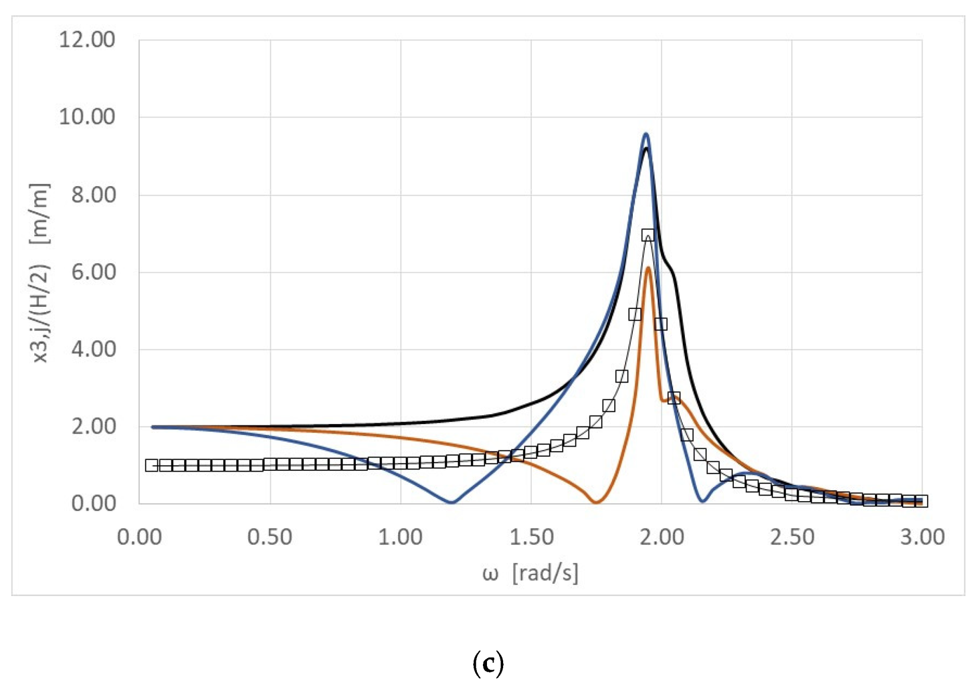
The results of Figure 9, Figure 10 and Figure 11 demonstrate that the presence of the breakwater behind the WEC array has a major impact on the converters’ efficiency. For L = D, the power efficiency (q factor) of every examined arrangement (i.e., C1, C2, C3) attains higher values than unity, in the majority of the examined wave frequencies, at every wave angle. Thus, the presence of the breakwater seems to have a positive impact on the arrays’ power absorption compared to the corresponding one of an array of five isolated WECs in the open sea (i.e., isolated case). On the other hand, for the L = 5D, 10D cases, at the frequencies where the value of the q factor is lower than unity, the breakwater has a negative effect on the arrays’ power absorption, whereas at the frequencies where q >1, the presence of the wall positively affects the arrays’ absorbed wave power compared to the isolated case. As far as the types of the WEC arrangements are concerned, it can be seen from Figure 9a, Figure 10a and Figure 11a that the q factor of the C1 arrangement attains higher values than in the C2 and C3 cases for the majority of the examined wave frequencies. On the other hand, the q factor of the C2 and C3 cases seems to attain higher values than unity in more wave frequencies than in the parallel arrangement. Taking all the above into consideration, it can be concluded that the parallel WEC wall arrangement (i.e., C1) and the L = D distance case lead to the best power absorption in the majority of the examined wave frequencies.
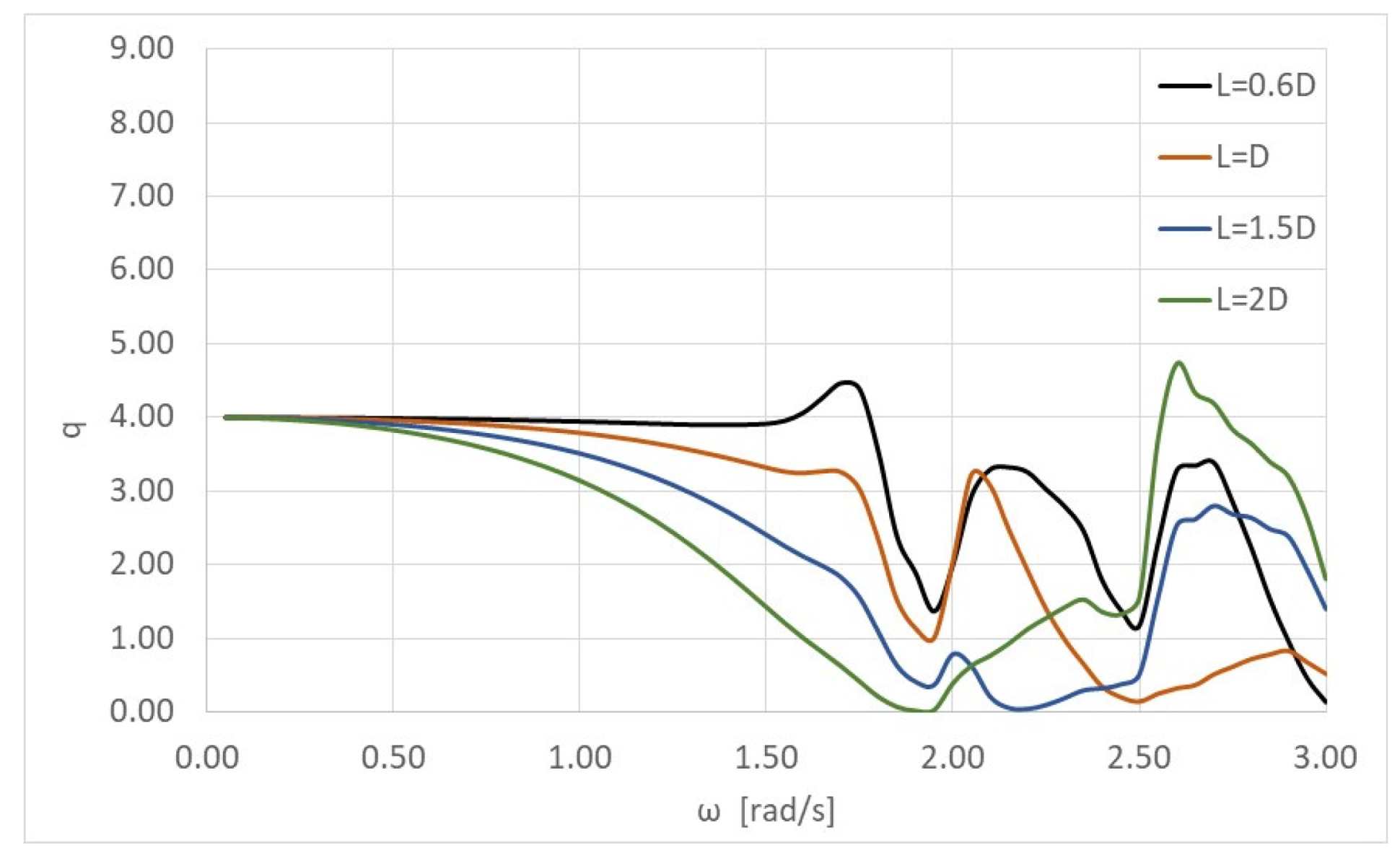
In order to find the critical value of L that maximizes the wave power absorption by the WEC array, three additional WEC–wall distance cases, in the neighborhood of the aforementioned L = D case, i.e., L = 0.6D, 1.5D and 2D, are examined. Herein, only the parallel WEC arrangement, C1, is considered, since the latter is found to be the optimum arrangement for maximum wave power absorption of an array in front of a breakwater. In Figure 12 the q factor of the C1 configuration (see Figure 2), for a zero-wave angle, is presented for the close-to-wall distance cases (i.e., L = 0.6D, D, 1.5D and 2D). It can be observed from the figure that for a wave frequency ω < 2 rad/s, the distance case that induces the maximum absorbed power by the array is L = 0.6D, whereas in the frequency range of 2 rad/s < ω < 2.5 rad/s, the cases L = 0.6D and L = D seem to attain higher values of absorbed power than the L = 1.5D and 2D cases. However, outside this frequency range, i.e., ω > 2.5 rad/s, the WEC arrays placed away from the wall, i.e., L = 1.5D and L = 2D, attain higher values of absorbed power than in the close-to-wall cases (i.e., L = 0.6D and D), for ω > 2.5 rad/s and ω > 2.75 rad/s, respectively. Consequently, from Figure 12 it can be derived that the L = 0.6D and L = D distance cases attain the most enhanced power absorption by the WEC array.
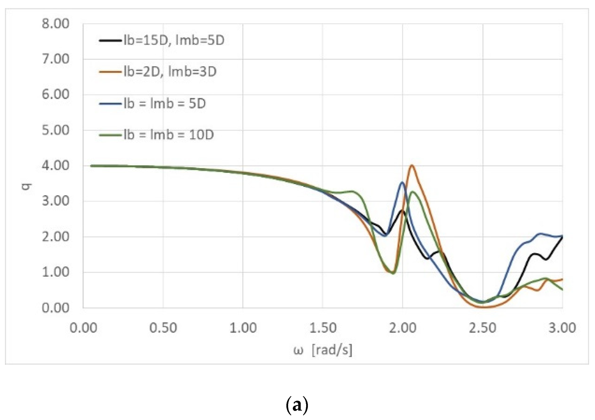
The effect of the inter-body spacing on the arrays’ efficiency is examined in the below figures. Herein, only the parallel arrangement, C1 (see Figure 13), is considered, since this has been found to be the most proper arrangement in terms of power absorption enhancement. The dimensionless parameters defining the system are the same as in the previous configurations, i.e., radius D = 2, draught (d−h)/D = 1, water depth d/D = 5, and distance from the wall L/D = 1, 5, 10. Four different inter-body spacing cases are examined, i.e., lb = 15D, lmb = 5D, lb = 2D lmb = 3D, lb = lmb = 5D and lb = lmb = 10D, for the θ = 0° wave angle case. The lb denotes the inter-body spacing between the 1st and the 2nd body (also the distance between the 4th and the 5th body) and lmb the inter body spacing between the 2nd and the 3rd body (also the distance between the 3rd and the 4th body) (see Figure 13). In addition to the equal distances between the WECs of the array, unequal distances were chosen to be examined in order to study their impact on the WECs performance.
In Figure 14 the q factor of the WEC arrangement is presented for the above inter-body spacing cases, for L/D = 1 and 5. It can be seen in Figure 14a that for a wave frequency ω < 1.5 rad/s the inter-body spacing between the WECs does not affect the arrays’ efficiency since comparable results can be reported for each examined case. However, for wave frequencies outside this frequency range (i.e., ω > 1.5 rad/s) the results differentiate. The same conclusion can be drawn also from Figure 14b. Specifically, for the lower-frequency band (i.e., ω < 1.5 rad/s), the examined inter-body spacing cases do not introduce any significant discrepancies in the q factor value. On the other hand, for ω > 1.5 rad/s the lmb = 3D and lb = 2D cases (i.e., the more dense examined WEC array) lead to an increase of the array’s q factor. It is worthwhile to mention that due to the type of the examined arrangement, with respect to the wave direction (i.e., parallel configuration, θ = 0° case), the inter-body spacing affects the array’s absorbed power, but not to such a great extent. However, in the WEC array case that is arranged perpendicular to the wall, for θ = 0°, the inter-body spacing is expected to have a significant impact on the array’s efficiency. This can be traced back to the appearance of near trapped waves between the converters as presented in [41].
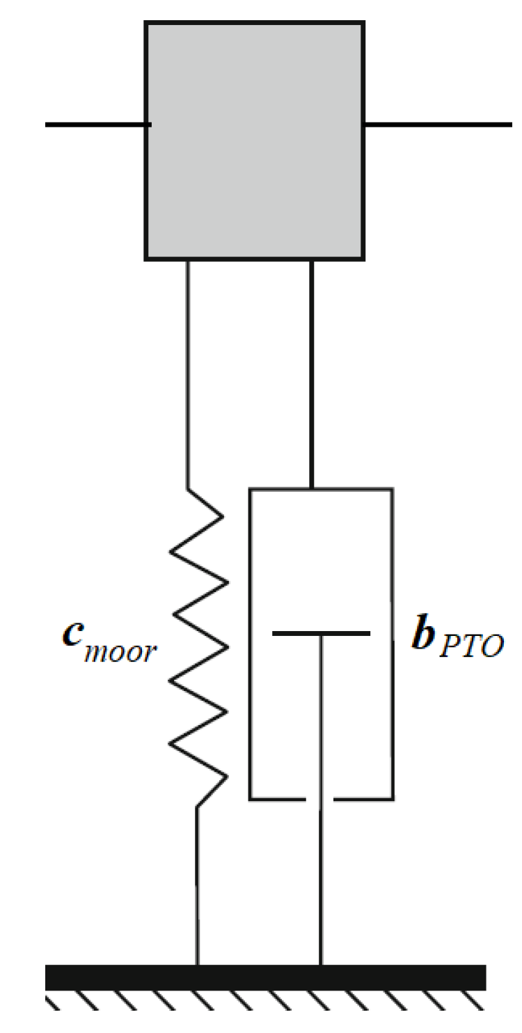
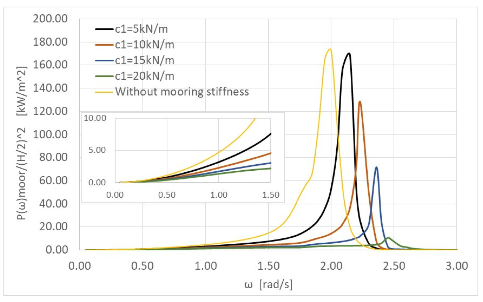
Next, additional stiffness due to moorings is considered. The WEC–mooring system is treated as a single degree of freedom system as illustrated in Figure 15. All the WECs are assumed to have the same mooring stiffness, i.e.,. Four different values of are examined, i.e., . Herein, for comparison reasons, all the WECs are also assumed to have the aforementioned PTO characteristics, i.e., bPTO = 446.9 kg/s. In Figure 16 the total absorbed power by the WECs for various values of mooring stiffness, P(ω)moor (see Equation (15)), (i.e., the WECs are placed in a parallel direction to the wall, with inter-body spacing lmb = lb = 10D and distance from the wall L = D) is presented, assuming wave heading angle θ = 0°. The results are compared with the corresponding absorbed power by the array without taking into consideration the mooring stiffness.
It can be observed from Figure 16 that the additional mooring stiffness imposes a shifting of the WEC’s natural frequencies to higher values, where the total absorbed power attains higher values than the no-mooring case. Nevertheless, for the remaining wave frequencies the additional stiffness due to mooring has a negative effect on the total absorbed power by the WEC array.
5. Conclusions
This study dealt with the theoretical evaluation of the efficiency of an array of WECs placed in front of a reflecting vertical breakwater. The image method has been applied to simulate the effect of the breakwater on the array, and the multiple scattering approach has been used to evaluate the interaction phenomena between the WECs.
Three different types of array configurations in front of the vertical wall have been investigated, i.e., a parallel, a perpendicular and a rectangular arrangement, for various cases of distances from the wall, inter body spacing, wave heading angles and mooring stiffness values. Based on the theoretical computations shown and discussed in the dedicated sections, the main findings of the present research contribution concern the effect of the breakwater on the WECs’ absorbed power, which should not be neglected when designing a WEC array in front of a vertical wall. This effect, the significance of which depends on (a) the distances between the converters and the wall, (b) the inter body spacing, (c) the angle of the incoming wave, (d) the type of the arrangement with respect to the incident wave direction, and (e) the value of the mooring stiffness, can lead to an increase of the values of the arrays’ absorbed wave power at specific wave frequencies. The presented figures showed that the most power-efficient WEC arrangement is the one parallel to the breakwater. As far as the optimum distance between the converters and the wall is concerned, it has been derived that the close-to-wall distance cases are more power-efficient in the majority of the wave frequencies compared to the absorbed power by arrays placed farthest from the wall. Although the distance between the WECs and the wall affects the system’s efficiency, the inter-body spacing, for the parallel array arrangement, does not seem to affect the absorbed wave power by the WECs. Also, when no additional mooring stiffness is being considered, the efficiency of the WECs increases compared to the examined WEC mooring cases.
Furthermore, compared to the no-wall array, the presence of the wall has a positive impact on the system’s power absorption since it results in a significant increase in the absorbed power, in the majority of the wave frequencies, for every examined arrangement, wave angle and inter-body spacing. This positive effect is amplified for the parallel, close-to-wall case for every incoming wave angle.
The effect of the breakwater on the energy performance of a WEC system is considered efficient overall, irrespectively of the system characteristics. Nevertheless, this positive effect can be optimized by proper selection of (a) the WECs’ dimensions, (b) the type of the arrangement with respect to the incoming wave, (c) the distance of the WECs from the wall, and (d) their inter-body spacing with respect to the wave properties at the installation site.
Author Contributions
Conceptualization, S.A.M.; methodology, S.A.M., D.N.K; software, S.A.M., D.N.K.; validation, D.N.K.; investigation, D.N.K., S.A.M.; data curation, D.N.K.; writing—original draft preparation, D.N.K.; writing—review and editing, S.A.M.; supervision, S.A.M.; project administration, S.A.M. All authors have read and agreed to the published version of the manuscript.
Funding
This research received no external funding.
Conflicts of Interest
The authors declare no conflicts of interest.
Appendix A
In Table A1, Table A2 and Table A3 the modulus and the phase of the heave responses of the 1st WEC device of the C1, C2, C3 arrangement are presented against indicative values of wave frequencies. Here the wave heading angle equals 0°.

Table A1.
Heave responses (modulus and phase) of the 1st WEC device for the C1 arrangement.
| L = D | L = 5D | L = 10D | ||||
|---|---|---|---|---|---|---|
| ω | Modulus | Phase | Modulus | Phase | Modulus | Phase |
| 0.2000 | 2.0008 | 0.0003 | 1.9613 | 0.0003 | 1.8393 | 0.0004 |
| 0.4000 | 2.0038 | 0.0012 | 1.8400 | 0.0015 | 1.3562 | 0.0022 |
| 0.5000 | 2.0064 | 0.0020 | 1.7435 | 0.0025 | 0.9946 | 0.0037 |
| 0.7000 | 2.0157 | 0.0043 | 1.4618 | 0.0059 | 0.0544 | 0.0122 |
| 0.8000 | 2.0235 | 0.0059 | 1.2661 | 0.0089 | 0.4973 | −3.1334 |
| 1.0000 | 2.0516 | 0.0108 | 0.7271 | 0.0199 | 1.5992 | −3.1281 |
| 1.2000 | 2.1144 | 0.0202 | 0.0672 | 3.1071 | 2.2104 | −3.1234 |
| 1.3000 | 2.1718 | 0.0279 | 0.5816 | −3.1124 | 2.0358 | −3.1146 |
| 1.5000 | 2.4166 | 0.0613 | 1.8569 | −3.0789 | 0.0674 | −2.8550 |
| 1.7000 | 3.3197 | 0.1951 | 3.7393 | −2.9835 | 3.5448 | 0.1435 |
| 1.9000 | 6.0516 | 0.7489 | 8.5278 | −2.5052 | 3.7537 | 0.6989 |
| 2.0000 | 5.7637 | 1.8289 | 4.8576 | −1.1047 | 3.3664 | −0.6393 |
| 2.2000 | 1.2536 | 2.9904 | 0.6132 | 2.6193 | 1.8353 | −0.3297 |
| 2.3000 | 0.5786 | −3.0874 | 0.8055 | 2.9180 | 0.2097 | −0.4343 |
| 2.5000 | 0.1110 | −2.8392 | 0.4916 | 2.6394 | 0.4678 | 2.6346 |
| 2.7000 | 0.0941 | −0.5789 | 0.1694 | −3.0218 | 0.2451 | −0.2786 |
| 2.8000 | 0.0831 | −0.1999 | 0.0772 | −0.0923 | 0.2160 | −0.4910 |
| 3.0000 | 0.0447 | −0.0520 | 0.0898 | −0.4302 | 0.0917 | 2.7800 |
Table A2.
Heave responses (modulus and phase) of the 1st WEC device for the C2 arrangement.
| L = D | L = 5D | L = 10D | ||||
|---|---|---|---|---|---|---|
| ω | Modulus | Phase | Modulus | Phase | Modulus | Phase |
| 0.2000 | 2.0014 | 0.0003 | 1.9439 | 0.0004 | 1.8063 | 0.0005 |
| 0.4000 | 2.0059 | 0.0019 | 1.7682 | 0.0027 | 1.2295 | 0.0036 |
| 0.5000 | 2.0093 | 0.0035 | 1.6284 | 0.0048 | 0.8049 | 0.0064 |
| 0.7000 | 2.0176 | 0.0083 | 1.2240 | 0.0098 | 0.2591 | −3.1390 |
| 0.8000 | 2.0232 | 0.0111 | 0.9501 | 0.0122 | 0.8494 | −3.1326 |
| 1.0000 | 2.0453 | 0.0162 | 0.2281 | 0.0236 | 1.8822 | −3.1233 |
| 1.2000 | 2.1085 | 0.0232 | 0.7503 | −3.1085 | 2.0669 | −3.1163 |
| 1.3000 | 2.1748 | 0.0303 | 1.3225 | −3.1070 | 1.5060 | −3.1055 |
| 1.5000 | 2.4347 | 0.0809 | 2.5325 | −3.0725 | 1.1436 | 0.0545 |
| 1.7000 | 3.1884 | 0.1717 | 3.4615 | −2.9981 | 3.6184 | 0.1323 |
| 1.9000 | 6.8404 | 1.0488 | 2.8544 | −2.0463 | 2.6023 | −2.5470 |
| 2.0000 | 3.8435 | 1.6568 | 2.5416 | 2.7659 | 7.8437 | −0.8686 |
| 2.2000 | 1.2622 | −3.1016 | 1.5394 | 2.7891 | 0.4806 | 0.4493 |
| 2.3000 | 0.5502 | −2.9091 | 1.1892 | 2.8538 | 0.8812 | 2.8927 |
| 2.5000 | 0.2347 | −2.2849 | 0.1617 | 3.0906 | 0.0818 | −3.0315 |
| 2.7000 | 0.0881 | −0.6917 | 0.2237 | −0.1849 | 0.1847 | −0.4820 |
| 2.8000 | 0.1035 | 0.2892 | 0.2167 | −0.6014 | 0.0788 | 3.1056 |
| 3.0000 | 0.0724 | −0.0201 | 0.0052 | −0.0492 | 0.0231 | 2.7385 |
Table A3.
Heave responses (modulus and phase) of the 1st WEC device for the C3 arrangement.
| L = D | L = 5D | L = 10D | ||||
|---|---|---|---|---|---|---|
| ω | Modulus | Phase | Modulus | Phase | Modulus | Phase |
| 0.2000 | 2.0019 | 0.0006 | 1.9622 | 0.0007 | 1.8401 | 0.0007 |
| 0.4000 | 2.0057 | 0.0024 | 1.8415 | 0.0024 | 1.3577 | 0.0026 |
| 0.5000 | 2.0097 | 0.0037 | 1.7460 | 0.0040 | 0.9969 | 0.0045 |
| 0.7000 | 2.0204 | 0.0078 | 1.4655 | 0.0081 | 0.0571 | 0.0215 |
| 0.8000 | 2.0308 | 0.0112 | 1.2705 | 0.0122 | 0.4965 | −3.1324 |
| 1.0000 | 2.0628 | 0.0197 | 0.7355 | 0.0239 | 1.6085 | −3.1218 |
| 1.2000 | 2.1451 | 0.0182 | 0.0578 | 3.1055 | 2.2208 | −3.1241 |
| 1.3000 | 2.2337 | 0.0545 | 0.5778 | −3.1087 | 2.0866 | −3.0936 |
| 1.5000 | 2.4939 | 0.1083 | 1.9252 | −3.0429 | 0.0983 | −2.9389 |
| 1.7000 | 3.2472 | 0.2510 | 3.8320 | −2.8967 | 3.6565 | 0.2412 |
| 1.9000 | 7.1944 | 1.1433 | 8.8875 | −2.1145 | 5.2251 | 0.9882 |
| 2.0000 | 4.1945 | 2.2283 | 4.0644 | −0.8197 | 2.4805 | −1.0937 |
| 2.2000 | 1.1219 | −3.0935 | 0.4064 | 2.7441 | 1.8300 | −0.2992 |
| 2.3000 | 0.5504 | −3.0650 | 0.7905 | 2.9267 | 0.2236 | 0.0693 |
| 2.5000 | 0.1351 | −1.9768 | 0.5312 | 2.6718 | 0.5642 | 2.6916 |
| 2.7000 | 0.0765 | −0.4791 | 0.1220 | 3.1242 | 0.2068 | −0.0698 |
| 2.8000 | 0.0490 | 0.2306 | 0.0303 | −0.2045 | 0.2361 | −0.3223 |
| 3.0000 | 0.0905 | 0.0835 | 0.1137 | 0.0724 | 0.1148 | −3.0764 |
References
- Falnes, J. A review of wave-energy extraction. Mar. Struct. 2007, 20, 185–201. [Google Scholar] [CrossRef]
- McCormick, M.E. Ocean Wave Energy Conversion; Courier Corporation: North Chelmsford, MA, USA, 1981. [Google Scholar]
- Pelc, R.; Fujita, R.M. Renewable energy from the ocean. Mar. Policy 2002, 26, 471–479. [Google Scholar] [CrossRef]
- Aderinto, T.; Li, H. Ocean wave energy converters: Status and challenges. Energies 2018, 11, 1250. [Google Scholar] [CrossRef] [Green Version]
- MacGillivray, A.; Jeffrey, H.; Hanmer, C.; Magagna, D.; Raventos, A.; Badcock-Broe, A. Ocean Energy Technology: Gaps and Barriers. SI Ocean: 2013. Available online: www.si-ocean.eu (accessed on 1 February 2020).
- Belibassakis, K.; Bonovas, M.; Rusu, E. Novel method for estimating wave energy converter performance in variable bathymetry regions and applications. Energies 2018, 11, 2092. [Google Scholar] [CrossRef] [Green Version]
- Bonovas, M.; Belibassakis, K.; Rusu, E. Multi-DOF WEC performance in variable bathymetry regions using a hybrid 3D BEM and optimization. Energies 2019, 12, 2108. [Google Scholar] [CrossRef] [Green Version]
- Mustapa, M.A.; Yaakob, O.B.; Ahmed, Y.M.M.; Rheem, C.K.; Koh, K.K.; Faizul, A.A. Wave energy device and breakwater integration: A review. Renew. Sustain. Energy Rev. 2017, 77, 43–58. [Google Scholar] [CrossRef]
- Vicinanza, D.; Margheritini, L.; Kofoed, J.P.; Buccino, M. The SSG wave energy converter: Performance, status and recent developments. Energies 2012, 5, 193–226. [Google Scholar] [CrossRef] [Green Version]
- Mavrakos, S.A.; Katsaounis, G.M.; Nielsen, K.; Lemonis, G. Numerical performance investigation of an array of heaving wave power converters in front of a vertical breakwater. In Proceedings of the 14th International Offshore and Polar Engineering Conference (ISOPE 2004), Toulon, France, 23–28 May 2004. [Google Scholar]
- Mavrakos, S.A.; Katsaounis, G.M.; Kladas, A.; Kimoulakis, N. Numerical and experimental investigation of performance of heaving WECs coupled with DC generators. In Proceedings of the 9th European Wave and Tidal Energy Conference, Southampton, UK, 5–9 September 2011. [Google Scholar]
- McIver, P.; Porter, R. The motion of a freely floating cylinder in the presence of a wall and the approximation of resonances. J. Fluid Mech. 2016, 795, 581–610. [Google Scholar] [CrossRef] [Green Version]
- Teng, B.; Ning, D.Z. Wave diffraction from a uniform cylinder in front of a vertical wall. Ocean Eng. 2003, 21, 48–52. [Google Scholar]
- Teng, B.; Ning, D.Z.; Zhang, X.T. Wave radiation by a uniform cylinder in front of a vertical wall. Ocean Eng. 2004, 31, 201–224. [Google Scholar] [CrossRef]
- Zheng, S.; Zhang, Y. Wave diffraction from a truncated cylinder in front of a vertical wall. Ocean Eng. 2015, 104, 329–343. [Google Scholar] [CrossRef]
- Zheng, S.; Zhang, Y. Wave radiation from a truncated cylinder in front of a vertical wall. Ocean Eng. 2016, 111, 602–614. [Google Scholar] [CrossRef]
- Konispoliatis, D.N.; Mavrakos, S.A. Theoretical performance investigation of a vertical cylindrical oscillating water column device in front of a vertical breakwater. J. Ocean Eng. Mar. Energy 2019. [Google Scholar] [CrossRef]
- Schay, J.; Bhattacharjee, J.; Soares, C.G. Numerical modelling of a heaving point absorber in front of a vertical wall. In Proceedings of the 32nd International Conference on Ocean, Offshore and Arctic Engineering, 9–14 June 2013; Volume 8. Paper No. OMAE2013-11491. [Google Scholar]
- Spring, B.W.; Monkmeyer, P.L. Interaction of plane waves with a row of cylinders. In Proceedings of the 3rd Specialty Conference of Civil Engng in Oceans (ASCE), Newark, DE, USA, 9–12 June 1975; pp. 979–998. [Google Scholar]
- Yeung, R.W.; Sphaier, S.H. Wave-interference effects on a truncated cylinder in a channel. J. Eng. Math. 1989, 23, 95–117. [Google Scholar] [CrossRef]
- Mavrakos, S.A. The scattered wave field by vertical cylinders in a narrow tank. In Proceedings of the 4th National Symposium on Theoretical and Applied Mechanics, Xanthi, Greece, 26–29 June 1995; Volume II, pp. 819–829. [Google Scholar]
- Butler, B.P.; Thomas, G.P. The diffraction of water waves by an array of circular cylinders in a channel. Ocean Eng. 1993, 20, 295–311. [Google Scholar] [CrossRef]
- McIver, P. The wave field scattered by a vertical cylinder in a narrow wave tank. Appl. Ocean Res. 1993, 15, 25–37. [Google Scholar] [CrossRef]
- Loukogeorgaki, E.; Chatjigeorgiou, I. Hydrodynamic performance of an array of wave energy converters in front of a vertical wall. In Proceedings of the 13th European Wave and Tidal Energy Conference (EWTEC, 2019), Naples, Italy, 1–6 September 2019. [Google Scholar]
- Loukogeorgaki, E.; Boufidi, I.; Chatjigeorgiou, I. Performance of an array of oblate spheroidal heaving wave energy converters in front of a wall. Water 2020, 12, 188. [Google Scholar] [CrossRef] [Green Version]
- Zhao, X.L.; Ning, D.Z.; Zhang, C.W.; Liu, Y.Y.; Kang, H.G. Analytical study on an oscillating buoy wave energy converter integrated into a fixed box-type breakwater. Math. Probl. Eng. 2017, 3960401. [Google Scholar] [CrossRef]
- Zhao, X.L.; Ning, D.Z.; Liang, D.F. Experimental investigation on hydrodynamic performance of a breakwater-integrated WEC system. Ocean Eng. 2019, 171, 25–32. [Google Scholar] [CrossRef]
- Howe, D.; Nader, J.R. OWC WEC integrated within a breakwater versus isolated: Experimental and numerical theoretical study. Mar. Energy 2017, 20, 165–182. [Google Scholar] [CrossRef]
- He, F.; Huang, Z.; Law, A.W.K. Hydrodynamic performance of a rectangular floating breakwater with and without pneumatic chambers: An experimental study. Ocean Eng. 2012, 51, 16–27. [Google Scholar] [CrossRef]
- Zheng, X.; Zeng, Q.; Liu, Z. Hydrodynamic performance of rectangular heaving buoys for an integrated floating breakwater. J. Mar. Sci. Eng. 2019, 7, 239. [Google Scholar] [CrossRef] [Green Version]
- Ning, D.Z.; Zhao, X.L.; Chen, L.F.; Zhao, M. Hydrodynamic performance of an array of wave energy converters integrated with a pontoon-type breakwater. Energies 2018, 11, 685. [Google Scholar] [CrossRef] [Green Version]
- Martins-rivas, H.; Mei, C.C. Wave power extraction from an oscillating water column at the tip of a breakwater. J. Fluid Mech. 2009, 626, 395–414. [Google Scholar] [CrossRef]
- Martins-rivas, H.; Mei, C.C. Wave power extraction from an oscillating water column along a straight coast. Ocean Eng. 2009, 36, 426–433. [Google Scholar] [CrossRef]
- Naty, S.; Viviano, A.; Foti, E. Wave energy exploitation system integrated in the coastal structure of a Mediterranean port. Sustainability 2016, 8, 1342. [Google Scholar] [CrossRef] [Green Version]
- Konispoliatis, D.N.; Mavrakos, S.A.; Katsaounis, G.M. Theoretical evaluation of the hydrodynamic characteristics of arrays of vertical axisymmetric floater of arbitrary shape in front of a vertical breakwater. J. Mar. Sci. Eng. 2020, 8, 62. [Google Scholar] [CrossRef] [Green Version]
- Mavrakos, S.A.; Koumoutsakos, P. Hydrodynamic interaction among vertical axisymmetric bodies restrained in waves. Appl. Ocean Res. 1987, 9, 128–140. [Google Scholar] [CrossRef]
- Mavrakos, S.A. Hydrodynamic coefficients for groups of interacting vertical axisymmetric bodies. Ocean Eng. 1991, 18, 485–515. [Google Scholar] [CrossRef]
- Mavrakos, S.A.; McIver, P. Comparison of methods for computing hydrodynamic characteristics of arrays of wave power devices. Appl. Ocean Res. 1997, 19, 283–291. [Google Scholar] [CrossRef]
- Falnes, J. Ocean Waves and Oscillating Systems: Linear Interactions Including Wave-Energy Extraction; Cambridge University Press: Cambridge, UK, 2002. [Google Scholar]
- Faltinsen, O.M. Sea Loads on Ships and Offshore Structures; Cambridge University Press: Cambridge, UK, 1990. [Google Scholar]
- Konispoliatis, D.N.; Chatijigeorgiou, I.K.; Mavrakos, S.A. Near trapped wave phenomena in an array of truncated cylinders in a perpendicular arrangement in front of a vertical breakwater. J. Appl. Math. Model. 2020. [Google Scholar] [CrossRef]
Figure 1.
2-D representations of a random array of N cylindrical Wave Energy Converters (WECs) in front of a breakwater: (a) plane view of array of N WECs in front of a breakwater; (b) side view of two adjacent WECs in front of a breakwater.
Figure 1.
2-D representations of a random array of N cylindrical Wave Energy Converters (WECs) in front of a breakwater: (a) plane view of array of N WECs in front of a breakwater; (b) side view of two adjacent WECs in front of a breakwater.

Figure 2.
Three different examined WEC array configurations with respect to the incoming wave direction: (a) the array is placed in parallel arrangement to the wall, C1; (b) the array is placed in a rectangular arrangement in front of the wall, C2; and (c) the array is arranged perpendicularly to the wall, C3.

Figure 3.
Dimensionless heave displacement of the 1st WEC, j = 1, of the parallel to the wall array, against ω, for three different examined distances from the vertical wall and three wave heading angles. Comparisons are made for the heave displacements of the same converter of the array without the presence of the breakwater: (a) θ = 0°; (b) θ = 45°; (c) θ = 60°.


Figure 4.
Dimensionless heave displacement of the 3rd WEC, j = 3, of the parallel to the wall array, against ω, for three different examined distances from the vertical wall and three wave heading angles. Comparisons are made for the heave displacements of the same converter of the array without the presence of the breakwater: (a) θ = 0°; (b) θ = 45°; (c) θ = 60°.


Figure 5.
Dimensionless heave displacement of the 1st WEC, j = 1, of the rectangular to the wall array, against ω, for three different examined distances from the vertical wall and three wave heading angles. Comparisons are made for the heave displacements of the same converter of the array without the presence of the breakwater: (a) θ = 0°; (b) θ = 45°; (c) θ = 60°.


Figure 6.
Dimensionless heave displacement of the 3rd WEC, j = 3, of the rectangular to the wall array, against ω, for three different examined distances from the vertical wall and three wave heading angles. Comparisons are made for the heave displacements of the same converter of the array without the presence of the breakwater: (a) θ = 0°; (b) θ = 45°; (c) θ = 60°.


Figure 7.
Dimensionless heave displacement of the 1st WEC, j = 1, of the array arranged perpendicularly to the wall, against ω, for three different examined distances from the vertical wall and three wave heading angles. Comparisons are made for the heave displacements of the same converter of the array without the presence of the breakwater: (a) θ = 0°; (b) θ = 45°; (c) θ = 60°.


Figure 8.
Dimensionless heave displacement of the 3rd WEC, j = 3, of the array arranged perpendicularly to the wall, against ω, for three different examined distances from the vertical wall and three wave heading angles. Comparisons are made for the heave displacements of the same converter of the array without the presence of the breakwater: (a) θ = 0°; (b) θ = 45°; (c) θ = 60°.


Figure 9.
The q factor term of the WEC array, against ω, for the three different WEC–wall distance cases and for 0° wave heading angle. Comparison concerning the q factor of the same array without the presence of the breakwater: (a) parallel arrangement; (b) rectangular arrangement; (c) perpendicular arrangement.

Figure 10.
The q factor term of the WEC array, against ω, for the three different WEC–wall distance cases and for 45° wave heading angle. Comparison concerning the q factor of the same array without the presence of the breakwater: (a) parallel arrangement; (b) rectangular arrangement; (c) perpendicular arrangement.

Figure 11.
The q factor term of the WEC array, against ω, for the three different WEC–wall distance cases and for 60° wave heading angle. Comparison concerning the q factor of the same array without the presence of the breakwater: (a) parallel arrangement; (b) rectangular arrangement; (c) perpendicular arrangement.

Figure 12.
The q factor term of the parallel to the wall WEC array, against ω, for 0° wave heading angle and for distances L = 0.6D, D, 1.5D, and 2D.
Figure 12.
The q factor term of the parallel to the wall WEC array, against ω, for 0° wave heading angle and for distances L = 0.6D, D, 1.5D, and 2D.

Figure 13.
Examined WEC array configuration placed in parallel arrangement to the wall.

Figure 14.
The q factor term of the WEC array, against ω, for the four different inter-body spacing cases: (a) the distance of the array from the breakwater equals L = D; (b) the distance of the array from the breakwater equals L = 5D.
Figure 14.
The q factor term of the WEC array, against ω, for the four different inter-body spacing cases: (a) the distance of the array from the breakwater equals L = D; (b) the distance of the array from the breakwater equals L = 5D.


Figure 15.
A mechanical system with one degree of freedom.

Figure 16.
Total absorbed power by the WEC array for four different mooring stiffness values. Here the WECs are placed in a parallel to the wall direction, with inter-body spacing lmb = lb = 10D and distance from the wall L = D. The results are compared also with the total absorbed power by the WEC, without mooring stiffness.

© 2020 by the authors. Licensee MDPI, Basel, Switzerland. This article is an open access article distributed under the terms and conditions of the Creative Commons Attribution (CC BY) license (http://creativecommons.org/licenses/by/4.0/).
Share and Cite
MDPI and ACS Style
Konispoliatis, D.N.; Mavrakos, S.A. Wave Power Absorption by Arrays of Wave Energy Converters in Front of a Vertical Breakwater: A Theoretical Study. Energies 2020, 13, 1985. https://0-doi-org.brum.beds.ac.uk/10.3390/en13081985
AMA Style
Konispoliatis DN, Mavrakos SA. Wave Power Absorption by Arrays of Wave Energy Converters in Front of a Vertical Breakwater: A Theoretical Study. Energies. 2020; 13(8):1985. https://0-doi-org.brum.beds.ac.uk/10.3390/en13081985
Chicago/Turabian StyleKonispoliatis, Dimitrios N., and Spyridon A. Mavrakos. 2020. "Wave Power Absorption by Arrays of Wave Energy Converters in Front of a Vertical Breakwater: A Theoretical Study" Energies 13, no. 8: 1985. https://0-doi-org.brum.beds.ac.uk/10.3390/en13081985
Note that from the first issue of 2016, this journal uses article numbers instead of page numbers. See further details here.