A Review of the Cascade Refrigeration System


1
School of Mechanical Engineering, Guangxi University, Nanning 530004, China
2
College of Light Industry and Food Engineering, Guangxi University, Nanning 530004, China
3
School of Electric Power, South China University of Technology, Guangzhou 510640, China
4
Systems, Power & Energy Research Division, School of Engineering, University of Glasgow, Glasgow G12 8QQ, UK
*
Author to whom correspondence should be addressed.
Energies 2020, 13(9), 2254; https://0-doi-org.brum.beds.ac.uk/10.3390/en13092254
Submission received: 26 December 2019
/
Revised: 4 March 2020
/
Accepted: 28 March 2020
/
Published: 4 May 2020
(This article belongs to the Section I: Energy Fundamentals and Conversion)
Abstract
:This paper provides a literature review of the cascade refrigeration system (CRS). It is an important system that can achieve an evaporating temperature as low as −170 °C and broadens the refrigeration temperature range of conventional systems. In this paper, several research options such as various designs of CRS, studies on refrigerants, and optimization works on the systems are discussed. Moreover, the influence of parameters on system performance, the economic analysis, and applications are defined, followed by conclusions and suggestions for future studies.
1. Introduction
Refrigeration technology plays an important role in human production and life; it is widely used in daily lives, commerce, and industrial production. The traditional single-stage compression refrigeration system (STCRS) and absorption refrigeration system (STARS) are two basic forms of the refrigeration technology. STCRS is used in air conditioning, human life, food storage, and transportation [1]. However, some applications, e.g., rapid freezing and the storage of frozen food, require rather low temperatures in the evaporator (ranging from −40 to −50 °C) [2], high compression ratio, or the high temperature difference in heat exchanger. In addition, the coefficient of performance (COP) and the volumetric efficiency of STCRS will be reduced by the high output temperature and pressure of the refrigerants [3]. STARS is commonly used for freezing applications and can effectively convert the low-grade waste heat into high-grade cold energy. However, when the temperature difference between cold energy and heat source increases, both COP and economy of STARS will decrease [4]; thus, the application of refrigeration system at a low evaporation temperature is seriously limited. Therefore, CRS has been proposed to achieve lower refrigeration temperatures. CRS has a wide range of applications, for example in the field of hypothermal medicine, cryopreservation for instrument, and cryogenics, e.g. liquefied gas [5]. It is also widely used in the storage and distribution of food, supermarkets, small refrigeration devices, air conditioning, etc. The system can conform to not only a suitable evaporation pressure at a lower evaporation temperature, but also a moderate condensation pressure at ambient temperature.
The two-stage cascade absorption refrigeration system (CARS) is a type of CRS that can operate with two or more different refrigerants; the performance of CARS with R744 and R717 as working fluids has been analyzed to realize the cold energy production at lower temperatures. The results show that CARS is very suitable for low heat source temperature and low refrigeration temperature system [6]. The two-stage vapor compression cascade refrigeration system (CCRS) is another commonly used CRS, consisting of two circuits—high-temperature cycle (HTC) and low-temperature cycle (LTC). The two circuits are connected to each other through a heat exchanger, which is simultaneously used as the condenser of the HTC and the evaporator of the LTC [7,8]. The design configuration of the two-stage CRS offers better cooling capacities and higher COP than that of STRS. However, the higher electricity consumption is a disadvantage of two-stage CRS; thus, a compression–absorption cascade refrigeration system (CACRS) driven by heat and power has been proposed to reduce electricity consumption [9]. This refrigeration system is in cascade with a compression system at LTC and an absorption system at HTC. The two subsystems operate with different refrigerants and the evaporation temperature can reach as low as −170 °C [10]. Many studies have confirmed that CACRS shows better performance than the two-stage CRS. For example, according to Garimella et al. [11], CACRS reduced the electricity demand by 31%, and increased COP, which was not the case for CCRS. To further meet demands, many studies related to structural optimization of CRS have been proposed [12,13,14,15,16,17,18]. For instance, applying ejector in CRS significantly improves the performance of cascade refrigeration [12,13]. Combining the solar with CRS not only optimizes the use of energy, but also improves the efficiency of the system [14]. A CRS powered by the organic Rankine cycle reduces CO2 emissions [15,16]. Moreover, some other types of refrigeration systems may be applied to make lower or upper cascade, e.g. a CRS with an inverse Brayton cycle on the cold side and an ammonia vapor compression cycle at the top is proposed for cold store applications; the system configuration has a 50% higher COP than the corresponding simple Brayton cycle at −50 °C [17]. A novel ejector–expansion TRCC (transcritical CO2) cascade refrigeration cycle which the top cycle is an ejector–expansion transcritical cycle and the bottom cycle is a sub-critical CO2 cycle is proposed [18]. Different low temperature technologies such as Stirling coolers have been compared with conventional refrigeration systems. The results show that Stirling and reciprocating steam compression refrigeration system had similar overall thermodynamic efficiency (14%), followed by the linear steam compression refrigeration system (8%), and then the thermoelectric cooler (1%) [19].
In this paper, we introduce four fundamental CRSs: CCRS, CARS, CACRS, and ACRS. The working principle of the system is elaborated first. Then, the development and application of the refrigerants in CRS secondly are presented. Third, studies related to the optimization of the performance of the systems are extensively reviewed to provide references for the research trends and possible further improvement of CRS. Fourth, various experiments regarding to CRS are reviewed, mainly focusing on the influence of parameters such as evaporation temperature, condensation temperature, temperature difference in heat exchanger, subcooling, and superheating on system performance. Fifth, an economic analysis is introduced, considering the thermoeconomic optimization to obtain the relationships among annual cost, exergy destruction, and COP. Finally, applications of CRS are extensively reviewed. This paper aims to provide useful information for further studies related to the refrigeration technology.
2. Different Cascade Refrigeration Systems
The cascade refrigeration system mainly includes four different systems: CCRS, CARS, CACRS, and ACRS. CCRS are comprised of two STCRSs and can achieve an evaporation temperature of −80 °C. CARS with two STARSs can also achieve a lower evaporation temperature. CACRS consists of a STCRS and a STARS, which are cascaded by a heat exchanger. ACRS realizes cascade between high and low boiling point components by an evaporative condenser; it has a wide application area and can easily achieve low evaporation temperature below −40 °C [20]. Table 1 shows the associated fluids and temperature ranges for the various CRS. In this part, we introduce these four different CRSs, respectively.
2.1. Two-Stage Compression Cascade Refrigeration System (CCRS)
STCRS is a traditional refrigeration system, which is widely used in air-conditioning systems. However, when the evaporation temperature continues to decrease, the single-stage compression system with a single refrigerant will be limited by too low evaporation pressure, which can even solidify the refrigerant. To solve these problems, two or more stage compression refrigeration systems should be cascaded by a heat exchanger, i.e. two-stage compression cascade refrigeration system (CCRS).
2.1.1. The Working Principle of CCRS
CCRS consists of two separate subsystems: one is a HTC, which usually uses NH3 as the refrigerant, and the other is a LTC, usually with CO2 as refrigerant [21]. Both cycles consist of a compressor, a condenser, an expansion valve, and an evaporator, and the two cycles are connected to each other through a heat exchanger, which is used as the condenser in the HTC and the evaporator in the LTC simultaneously (see Figure 1) [22].
2.1.2. The Working Fluids in CCRS
The selection of working fluids has a great influence on the system performance. In the selection of working fluids, besides thermodynamic properties, physical and chemical properties of working fluids should also be considered, such as toxicity, combustibility, explosivity, interaction with metal materials, interaction with lubricants, low boiling temperature, and atmospheric environmental friendliness. In addition, the critical temperature of refrigerant should be higher and the condensation temperature should be lower. The critical temperature determines whether the refrigerant can liquefy in the range of ordinary low temperature. The boiling point should be as low as possible to produce a lower temperature. Moreover, the evaporation pressure of the refrigerant should be close to or slightly higher than the atmospheric pressure to increase the chance of air mixing into the system. Table 2 shows the standard parameters of various refrigerants. In the past, the traditional CFCs and HCFCs refrigerants, such as R11, R12, R22, R13, R500, and R520, were widely used in CRS. However, these refrigerants have higher Ozone Depletion Potential (ODP), leading to ozone layer depletion [24]. HFCs do not affect the ozone layer and are regarded as a replacement for CFCs and HCFCs. However, HFCs highly contribute to global warming due to its high ODP values and high permanency in the atmosphere. Therefore, these refrigerants have been gradually phased out since 1996. According to Montreal Protocol and its amendments from the United Nations Environment Programme (UNEP), these have been prohibited since 2010 [25]. Therefore, finding new alternative refrigerants is a task of top priority. Environmentally friendly refrigerants, e.g. R744, R717, and hydrocarbons, have been developed [6]. R717 [26], R1270 [27], R170 [28], R600 [29], and R290 [30] are usually used in the HTC of CCRS, while R744 [31], R170 [32], R152a [26], R23 [26], and N2O [33] are widely used in the LTC of CCRS. R744 and R717 are the most widely used refrigerants in two-stage CCRS due to their good characteristics, which have been shown to be the most promising natural refrigerants across a broad spectrum of commercial and industrial refrigeration and air-conditioning systems [34]. R744 is a kind of non-toxic, nonflammable gas with a positive vapor pressure at low temperatures; therefore, it is suitable for the low temperate circuit [21]. Due to the high triple point of R744, the lowest refrigeration temperature is limited above −55 °C [19]. The triple point is a temperature and pressure value in thermodynamics that enables a substance to coexist in three phases (gas phase, liquid phase, and solid phase). It is worth mentioning that, when R744 is applied in ultra-low-temperature CRS, sedimentation of R744 may occur when the flow velocity, condensation temperature, and heating power are low. With the increase of mass flow rate, dry ice particles partly gather on the wall of the expansion tube, which causes the blockage. Therefore, we can add a heater on the inlet tube or increase the opening conditions to solve this problem; increasing the opening condition or the input heat fluxes can also avoid blockages [29]. R717, as an environmentally friendly refrigerant, has been widely used in CRS [21]. Moreover, its apparent disadvantages of toxicity and moderate flammability cannot be ignored [35]. R717 with air is flammable when its concentration is about 25% by volume [36]. Therefore, the current R717 refrigeration system should strengthen the pipeline welding and air tightness standards to avoid flammability and toxicity issues. It is worth mentioning that R290 and R717 have similar thermodynamic properties in CRS, and have no significant difference in economic and exergy efficiency objectives. R290 has 0 ODP and low GWP, but R290 has poor performance against chlorinated solvents and aromatics [23]. Moreover, the level of inherent safety of R717 is higher than R290 [30]. In addition to R744 and R717, mixture refrigerants, especially those exhibiting azeotropic phase equilibrium behaviors, have excellent performance in CRS. For instance, the binary mixture of R744 and R290 is regarded as a promising alternative to R13 when the evaporation temperature is above 201 K [37]. The ozone-friendly refrigerants pair R507A and R23 is considered as a replacement for CFC refrigerant R13 in low temperature applications. R507A is an azeotropic mixture comprised of R125 (50%) and R143a (50%) on a mass basis. R23 is a single component HFC refrigerant applied as replacement to CFC refrigerant [38]. Moreover, the options of low GWP refrigerant group for a three-stage CRS were developed by Sun et al. [39]. In the middle-temperature cycle, R41 and R170 could replace R23. To obtain a better performance, R170 would be considered first because the optimum condensation temperature of using R41 in MTC is higher than that of using R170 once the refrigerants of HTC and LTC were fixed. In HTC, refrigerants such as R717, R152a, and R161 would be recommended. Out of environmental and safety concern, R717 should be recommended as an environmentally-friendly refrigerant in the larger refrigeration system. Figure 2 shows the vapor-pressure curve of selected refrigerants, such as CFCs, HCFCs, HCFs, and HFOs. It can be seen that the vapor-pressure curve of R-1234yf is similar to those of R-12 and R-134a [40]. The selection of refrigerant facilitates timely conversion from CFC to HCFC, HCFC to HFC or HFO, and HFC or HFO to natural refrigerants [41].
Considering the advantages of the mixed refrigerants and the requirements of environmental protection, safety, and system performance, HFC/HFO mixed refrigerants are considered to be a promising alternative in the near future and even in the long term. For example, DR7 is the HFC/HFO blend of R32 and R1234yf, which is a novel low-GWP alternative to R404A with 94% lower GWP. This refrigerant is an alternative to low-charge R404A systems [42]. Mota-Babiloni et al. [43] summarized the research on HFC/HFO mixed refrigerants, as shown in Table 3.
2.1.3. The Various Designs Based on CCRS and Optimization
To improve performance, many efforts have been made to innovate CRS. For instance, some high energy efficient techniques have been presented to enhance the cascade performance, such as using an internal heat exchanger or expander to replace expansion valve. Moreover, applying two-phase ejector instead of the conventional expansion devices also significantly improves the performance of CRS [44]. In this section, we elaborate various designs based on CCRS and their optimization.
• A novel ejector–expansion CO2/NH3 cascade refrigeration cycles
The ejector is a mechanical device which conveys a low-pressure fluid to a higher-pressure fluid at a diffuser outlet by using a high pressure and velocity fluid. Because of its lower cost, no moving components, and ability to deal with two-phase fluid without harm, the ejector attracts attention in recent years [18]. The utilization of ejector not only can improve the cooling capacity and reduce the compressor power, but also can recover expansion process loss by isentropic expansion process to improve the performance of cascade refrigeration system [44]. COP of an ejector–expansion refrigeration system was tested. The authors concluded that COP of system with ejector was 15% higher than that of the conventional system [45]. Li et al. [46] proposed an experimental investigation on a modified CCRS that applied an ejector in LTC. An ultra-low-temperature freezer prototype with the proposed system was designed to test the performance of proposed system, and the results show that the energy consumption of prototype with proposed system was lower than that of the baseline freezer. Different from the above studies, applying two ejectors in both subsystems of the novel ejector–expansion CO2/NH3 cascade refrigeration cycles were proposed by Dokandari et al. [12]. Figure 3 shows the process of the novel system. The maximum COP of the novel system was increased by 7% compared to the conventional system. The utilization of ejectors leads to the result that the exergy destruction rate and exergy losses through expansion valves both decrease [12]. From these data, we can know that the utilization of the ejector has a positive effect on the cascade refrigeration system and the novel ejector–expansion CO2/NH3 cascade refrigeration cycle has good prospects for development.
• Various inventions related to cascade refrigeration systems
The high power consumption is still a big problem for two-stage CCRS. Therefore, many inventions aimed at reducing power consumption have gradually attracted people’s attention. Howard [47] proposed an invention to provide a method for operating a CCRS, wherein the power consumption of two compressors are monitored and the pressure and power values are transported to a process controller. This method could reduce the overall power consumption to achieve more efficient operating pressures compared to CCRS. Another invention has been proposed that combines temperature responsive flow mechanism with two-stage CCRS [48]. The controller operates a valve to increase the refrigerant flow according to the signal delivered from a temperature sensor at the evaporator output, thus the capacity of system is improved. This invention can greatly meet the larger cooling demands during periods of increased access [48].
• Three-stage cascade refrigeration system (TCRS)
Generally, the lowest evaporation temperature of two-stage CRS can only reach −80 °C; if the required evaporation temperature continues to decrease, for instance in the temperature range from −80 to −100 °C, multistage CRS consisting of three or more single-stage refrigeration cycles can also be selected [39]. Yoon et al. [49] designed a new natural gas liquefaction cycle with staged compression cycles and simulated the cycle with HYSYS software. This TCRS operated with R290, N2O, and N2. The results show that COP of this new cascade system was 25% higher than that of STCRS. Sun et al. [39] proposed a novel three-stage cascade refrigeration system that includes a LTC, a HTC, and a medium-temperature cycle (MTC). In the LTC evaporator, the working fluids absorb cooling load Qe from the cold space. The MTC refrigerant transfers the heat to the LTC refrigerant in CHX of LTC. Similarly, the MTC refrigerants transfer the heat to the HTC refrigerant in CHX of MTC. The amount of the heat transferred in CHX of LTC is equal to the sum of Qe and the input power of the LTC compressor. The amount of the heat transferred in CHX of MTC equals the sum of heat transferred in CHX of LTC and the input power of the MTC compressor [39]. It is possible to produce four-stage or even higher-stage CRS to achieve lower evaporation temperature. However, as the number of cascades increases, the system cost, such as the cost of rack and components, will also increase. Therefore, it is not economical to adopt multistage CRS.
To verify the superiority of CCRS, many experiments have been proposed. The performance comparison of STRS and two-stage CCRS has been proposed. The results indicate that CCRS could provide better refrigeration capacities for any given evaporation temperature than STRS because of the lower condensation temperature. However, the total compressor power in CCRS is higher than that of STRS due to the utilization of the second compressor in CCRS. To provide the same refrigeration capacity, CRS needs more power [50]. In addition, the performance comparison between CCRS and two-stage refrigeration system has been developed. The results show that CCRS is a better alternative to two-stage refrigeration system in commercial application (ranging from −30 °C to −50 °C) [2].
2.1.4. The Experimental Research of CCRS
Various parameters, such as evaporator temperature, condenser temperature, temperature differences in cascade heat exchanger, subcooling, and superheating, have an important influence on the performance of the system. To get the optimal performance, many experiments have been carried out. Wang et al. [51] discussed the performance of two-stage CCRS operating with CO2/NH3 as refrigerants and obtained the influence of parameters on system performance. With the increase of the evaporation temperature, COP of CCRS increases. With the increase of condensation temperature, both COP of CO2 cycle and cooling capacity all decrease sharply while COP of NH3 cycle has contrary tendency. Therefore, we can slightly reduce the condensation temperature of CO2 cycle to obtain a larger cooling capacity [38]. Moreover, in a similar study, an optimization work based on the optimum CO2 condensation temperature was conducted. With the increase of the CO2 evaporation and NH3 condensation temperatures, the CO2 optimum condensation temperature value increases. The correlation of condensation temperature is determined to obtain the CO2 optimal condensation temperature, as follows [6]:
According to Park et al. [52], when the temperature difference in cascade heat exchanger increases, COP decreases. Moreover, the optimal condensation temperature of the cascade–condense based on the given parameters, including TE, TC, and ΔT, has been presented [21]. Referring to the three design parameters, the maximum COP and optimal condensation temperature of the cascade–condense can be obtained from Equations (2) and (3).
where MC is the condensation temperature of LTC
As shown in Equation (2), as the TC, TE, and ΔT increase, the optimal condensation temperature of a cascade condenser increases. As shown in Equation (3), the maximum COP increases with increasing TE while decreases as TC or ΔT increases.
Different degrees of subcooling and superheating also have an effect on COP of CCRS under the condition that other operating parameters are constant; COP of cascade system rises with the degree of superheating in HTC and decreases with the degree of superheating in LTC; and the maximum COP significantly increases with the increase of subcooling and slightly increases with the increase of superheating [38].
The intermediate temperature level also has a significant effect on COP of CCRS, which is affected by the evaporation temperature of the HTC or the condensation temperature of the LTC. The optimal intermediate temperature will result in the maximum COP; with the increase of condensation temperature, the optimal intermediate temperature is also elevated and the relevant maximum COP will decrease. When the evaporation temperature increases, both the optimal intermediate temperature and relevant maximum COP escalate [52]. Moreover, the temperature difference in a cascade heat exchanger also has an effect on COP; when the temperature difference increases, the optimal intermediate temperature decreases. The optimum intermediate temperature level can be obtained to reach the best performance of the system [7].
2.1.5. Thermoeconomic Analysis of CCRS
As it is well known that CCRS effectively improves the performance compared to the traditional STRS. However, the cost of CCRS, such as the increasing cost of power supply as the number of cascades increases, and the efficiency of the cycle should not only to be considered, but also a series of economic problems. For example, when the temperature difference in cascade heat exchanger increases, COP of system decreases, but when the temperature difference in cascade decreases, heat exchanger size and cost will also increase. Therefore, as the size of the heat exchanger increases, the performance of the system can be improved but the cost of system also increases [53]. It is unrealistic to achieve the minimum cost and the highest efficiency at the same time. Therefore, thermoeconomic optimization is proposed to optimize the performance of cascade refrigeration. In this part, we elaborate on thermoeconomic optimization for CCRS. Because the parameters, working fluids, and calculation for different optimization processes are different, the optimized results will be different. Nasruddin et al. [53] applied thermoeconomic optimization to point out optimal operating parameter values of the system and address the relationship between exergy efficiency and costs. Similarly, Keshtkar [54] presented thermoeconomic optimization of CCRS operating with R717/R744 pairs; one multi-objective optimization strategy (MOS) was used in CCRS, which can achieve the best balance between thermodynamic efficiency and economic cost. Two single-objective optimization strategies (SOS), which consist of exergetic optimization and cost optimization, were used in CCRS. The first SOS is to maximize the exergetic efficiency while the second SOS is to minimize the total annual cost of the system. The simulation result shows that the first SOS could improve exergetic efficiency, and the consumption of the HTC and the LTC were reduced, while the second SOS not only could improve exergetic efficiency, but also could reduce the total system cost and consumption of work in the entire system. Apart from some components costs similar to those Keshtkar et al., the review structure of Rezayan et al. [3] added electricity costs to economical aspects, the annual cost of which is determined as an objective function, consisting of annualized capital and electricity costs of the system components. The result shows that, compared to the base case design for the same cooling capacity, annual cost of the system was reduced by 9.34%. Moreover, the result of exergy analysis on the optimized system also showed that the highest exergy destruction occurred in the condenser, while the lowest exergy destruction occurred in expansion valve of the R744 circuit [3]. According to Sholahudin et al. [32], two objective functions need to be optimized: the total annual cost including the capital and operational cost and the total exergy destruction. The results show that, with the increase of total cost, the exergy destruction obviously decreases while COP increases obviously. With the increase of R744 fraction, the cost of LTC compressor and condenser decrease, while the cost of evaporator and cascade condenser increase.
2.2. Cascade Absorption Refrigeration System (CARS)
2.2.1. The Working Principle of CARS
To get a lower evaporation temperature, CARS is proposed on the basis of STARS, using evaporator in HTC to cool condenser in LTC.
CARS consists of a NH3-H2O system and a LiBr-H2O system. The evaporator in LiBr-H2O HTC is used to cool the condenser in NH3-H2O. Figure 4 shows the schematic diagram of CARS [55]. Yang et al. proposed a CARS that is composed of a NH3-H2O cycle and a LiBr-H2O cycle to produce −40 °C cold energy using low-grade waste heat. Different parameters were investigated to get the maximum COP of developed system. The result shows that the maximum COP was 0.19 and exergy efficiency achieved 9.71%, respectively [56]. The economic performance of CARS was compared with that of industrial application. The results show that CARS has good adaptability, indicating that CARS will attract more attention on the waste heat recovery [56].
2.2.2. The Working Fluid in CARS
In CARS, NH3-H2O and LiBr-H2O are commonly used as refrigerants. However, crystallization may occur when the temperature of LiBr solution is too low or the concentration is too high. Therefore, it is difficult for the LiBr-H2O absorption system to work at a condensation temperature higher than 40 °C [57]. It is worth mentioning that the refrigeration temperature of LiBr-H2O must be above 0 °C [58]. Yang et al. [59] tested the performance of CARS operating with NH3-LiBr. The system was driven by low-grade waste heat below 150 °C and was applied to a coal-to-SNG project as a case study. The result shows that COP and absolute gain of proposed system were 0.17 and 3.4 × 10⁷ million CNY per year, respectively.
2.2.3. The Various Designs Based on CARS and Optimization
The absorption refrigeration system is an effective way to recover waste heat, which helps to reduce the energy consumption. The cascade method is an effective way to improve the performance of absorption refrigeration system. For example, the cascade of a Rankine cycle and an absorption refrigeration cycle has been proposed effectively. The HTC of the waste heat is used for power generation, while the LTC is used for refrigeration [60]. In addition, the residual heat of the power subsystem is recovered by the refrigeration subsystem. The simulation results show that, compared with the single power system and refrigeration system, the energy consumption of the system is reduced by 17.1% under the same output power [60].
2.2.4. The Experimental Research of CARS
In this section, the effects of many parameters on performance of system are introduced. Cui et al. [55] used NSGA-II technology to test the performance of CARS by energy, exergy, and economic (3E) analyses. The results show that, when the LiBr-H2O evaporator, NH3-H2O condenser, and absorber temperatures increased, COP decreased and exergy destruction increased, but the total heat transfer area and total annual cost decreased. Yang et al. [56] tested the performance analysis of a novel cascade absorption refrigeration (NCAR) for low-grade waste heat recovery. The NCAR system was composed of an NH3-H2O AR cycle and a LiBr-H2O AR cycle. The results indicate that COP of NCAR dropped with the decrease of LiBr condenser temperature, and increased quickly when the cold energy temperature increased. Moreover, the effects of the condenser temperature and absorber temperature on the performance of CARS have been investigated. With the increase of condenser temperature in the HTC, COP decreases gradually. With the increase of the absorber temperature in CARS, heat put at generator in the HTC does not change. When the evaporator temperature reaches −10 and 0 °C, heat output at the generator in the HTC decreases first and then increases, leading to the result that COP increases first and then decreases after reaching a peak [61].
2.2.5. Thermoeconomic Analysis of CARS
Based on the performance investigation of CARS from three aspects of energy, exergy, and economy, where the two objectives are total exergy destruction and total annual cost, it can be concluded from the optimization scheme that, when total exergy destruction achieves the minimum value and COP achieves the maximum value, the total cost is the highest [59]. When the total cost has minimum values, exergy destruction shows the highest value; therefore, we should adjust the balance between them under different cases [55]. Moreover, the result shows that the maximum exergy destruction occurred in generator and absorber, which accounted for 50% of the total exergy destruction [55].
2.3. The Compression–Absorption Cascade Refrigeration System (CACRS)
Although the two-stage CRS can produce low evaporating temperature, their higher electricity consumption is a serious problem. Under this circumstance, the compression–absorption cascade refrigeration system is proposed.
2.3.1. The Working Principle of CACRS
CACRS is another kind of CRS that can effectively improve the performance compared with the conventional refrigeration system. There are still many CACRSs driven by heat source, which can be engine flue gas, process waste heat, solar energy, etc. [9]. These systems can achieve a low-temperature refrigeration load (ranging from −40 to −50 °C) without power and electricity input. Chen et al. [9] proposed a novel system which consists of a heat-driven power generation subsystem with NH3-H2O mixture as the working fluid and an absorption–compression refrigeration subsystem. The results show that COP and cooling capacity of the proposed system improved compared to a heat-driven double-stage compression refrigeration system. The schematic diagram of CACRS is shown in Figure 5 [62].
2.3.2. The Working Fluid in CACRS
Because CACRS is similar with CCRS and CARS, the working fluids in CACRS are the same as those of CCRS and CARS. In this part, the experiments proposed by researchers are briefly introduced. NH3-H2O and LiBr-H2O as refrigerants are widely used in absorption cycle [7]. The first utilization of LiBr-H2O in CACRS was proposed by Cimsit and Ozturk [63], and the performance of LiBr-H2O fluid pair and NH3-H2O pair was compared. The results show that COP of the system with LiBr-H2O is 33% better than that of NH3-H2O under the same conditions. Many different refrigerants are applied in the vapor compression cycle of CACRS. For instance, the 0 ODP and low GWP refrigerants including R1234yf, R1234ze (E), and R1233zd (E) have been used in the vapor compression section. It is also worth mentioning that systems operating with R1234yf obtained a higher COP in the system based on LiBr-H2O, and the systems using R1234ze (E) obtained a higher COP in the system based on LiCl-H2O [64]. Jain et al. [65] introduced the size and cost estimation of CRCRS with R410A and LiBr as working fluid in the compression and absorption sections, which could be used as reference for designers in the manufacture and test of such systems.
2.3.3. The Various Designs based on CACRS and Optimization
To improve the performance, researchers have made many efforts to innovate cascade refrigeration systems. For example, the combination of compression–absorption cascade refrigeration system and organic Rankine cycle saves the environment energy effectively [16]; adding a second economizer and a condenser–generator to the absorption cycle in compression–absorption double-stage (CADS) system can improve COP of the system [66]; a solar driven dual-evaporator vapor compression–absorption cascade refrigeration system effectively saves the energy and improves the performance; etc. [14]. In this section, we introduce various designs based on CACRS and their optimization.
• Combined vapor compression–absorption cascade refrigeration system (CACRS) and organic Rankine cycle (ORC)
With the rise in fuel prices and environmental pollution, energy efficient, environmentally friendly, and commercially viable systems attract attention [67]. ORC can operate with low temperature energy sources, such as biomass [68], geothermal [69], solar thermal [70], ocean thermal [71], etc. energy. For example, Patel et al. [72] proposed a CACRS powered by solar–biomass organic Rankine cycle and evaluated the performance and commercial viability of the system. In another study, Patel et al. [16] proposed a new CACRS which powered by waste heat based on ORC. ORC provides input to the vapor compression refrigeration system and heat to the absorption refrigeration system. The optimization result shows that the annualized cost of the system was decreased by 12% compared to the base case. The break-even point and the simple payback period were, respectively, decreased by 3.48 and 4.50 years [16]. In summary, the combination of ORC and CACRS makes full use of the waste heat, which effectively cuts down the annualized cost of the system and improves the efficiency. In recent years, a novel trigeneration system based on organic quadrilateral cycle (QLC) integrated with CACRS for waste heat recovery has been proposed; using QLC to replace ORC in the combined system can not only improve the overall performance of the system from the perspective of energy and exergy under the same input value, but also generate electricity [73].
• A compression–absorption double-stage (CADS) system
A new novel compression–absorption double-stage cascade refrigeration system has been proposed. CADS is similar to CACRS, but a second economizer and a condenser–generator are added to the absorption cycle in CADS to improve COP of the system. The comparison between a compression–absorption single-stage (CASS) system and compression–absorption double-stage (CADS) system has been presented. The result shows that COP of CADS was higher than that of CASS compared to CASS and the heat supplied to the generator in CADS was reduced [66]. The circulation process is shown in Figure 6.
• A solar driven dual-evaporator vapor compression–absorption cascade refrigeration system
At present, renewable energy resources are being developed around the world, including solar energy, wind energy, biomass energy, geothermal energy, and tidal energy. Solar energy becomes the most promising alternative energy to generate electricity in the future due to its unique advantages [74]. The solar energy can be used in many applications, because it can be converted into useful heat through solar collectors or directly into electrical energy through photovoltaic panels [75,76]. Therefore, the solar assisted refrigeration system has been examined by many researchers in recent years. Furthermore, solar cooling/refrigeration applications can reduce the high peaks of electricity consumption in summer and solve severe problems in the grid energy distribution [77]. Bellos et al. [78] presented an analysis of a solar-assisted CACRS for various operating scenarios and evaluated the sustainability of this system. According to the results, the system could produce a lot of cooling capacity and save a lot of electric energy, and the financial indexes showed that the installation of the system was a feasible choice.
• The compression–absorption cascade refrigeration system powered by a cogeneration system
CACRS is powered by a cogeneration system that simultaneously provides electricity to the compression system and heat to the absorption system. The primary energy ratio is taken to test the possibility of the cascade system with a cogeneration system. The data show that the energy requirements of the cascade refrigeration system were significantly lower than the energy supplied by cogeneration system and there would be surplus energy for other applications; thus, the proposal that cascade refrigeration powered by cogeneration system should be discharged [7].
To test the superiority of CACRS, Garimella et al. [11] compared the performance of the two systems. The result shows that CACRS reduces electricity demand by 31% compared with an equivalent vapor-compression system. COP of CACRS is constantly higher than that of two-stage refrigeration system. Over the heat rejection temperature, the cascade refrigeration system has a constant advantage than two-stage vapor-compression system. In a similar study, the electric power consumption in a CACRS is 61% less than that of an independent STCRS and COP of the compression section is improved by 155% compared to STCRS [79].
2.3.4. The Experimental Research of CACRS
Many experiments are proposed to obtain the influence of different parameters on performance. Although the refrigerants, basic parameters, and methods in experimental research of CACRS are different, the conclusions are the same. Ansari et al. [80] applied a mathematical model to analyze energy and exergy efficiency of CACRS. With the increase of the generator temperature, COP increases to a maximum value and then decreases. With the evaporator temperature decreases, both COP and exergetic efficiency decrease while the irreversibility of the system decreases. When the condenser temperature increases, COP and exergetic efficiency both decrease while the irreversibility of the system increases [80]. In addition, Cimsit et al. [63] analyzed the effect of different parameters on performance of CACRS. The results show that, as the temperature difference increases, the general COP of the system decreases. With the increase of the condenser temperature, COP of the system decreases. Moreover, when the generator temperature increases, COP of absorption section and entire cascade cycle increases. According to Jain et al. [79], COP of the system increases with the increase of subcooling and decreases with the increase of superheating. COP of the system becomes lower when the temperature difference in cascade heat exchanger becomes larger. However, the lower values lead to the increase of the cost and size for cascade heat exchanger.
2.3.5. Thermoeconomic Analysis of CACRS
In this part, we elaborate on the thermoeconomic optimization for CACRS based on the review of existing literature. For CACRS, the electric power requirement of CACRS is reduced substantially compared to the conventional compression refrigeration system, while the total size of CACRS is increased in comparison with the conventional compression refrigeration system, and the running cost decreases because the utilization of available waste heat decreases [79]. When the condenser temperature becomes lower, the overall performance of the system from the point of view of energy and exergy analysis increases; however, the system size and cost also increase. The lower is the degree of the overlap, the better is the performance from energy and exergy points of view, but it is not economical [65]. Therefore, optimizing the system from thermal and economical aspects is essential. In CACRS, the exergy destruction consists of four parts: the first exergy destruction occurs when the working fluids absorb heat from heat source; the second exergy destruction and loss occurs when the heat rejects to the heat sink; since CACRS has more internal heat exchangers than the two-stage CCRS does, the third exergy destruction of CACRS is higher than that of CCRS; and the fourth exergy destruction occurs in all components such as the turbine, compressors, pumps, and valves. According to the optimization results proposed by Cimsit et al. [81], the evaporator equipage has maximum exergy destruction and exergy loss when it has the minimum exergy efficiency. The generator has the maximum exergy efficiency. Similarly, Salhi et al. [64] found that the highest irreversibility occurred in the generator, evaporator–condenser, and compressor. Moreover, the total irreversibility operated with LiCl-H2O was slightly higher than that operated with LiBr-H2O in the vapor compression section [64]. Jain et al. [82] carried out the thermoeconomic and environmental analyses based on the multi-objective optimization of CACRS using NSGA-II technique. The total irreversibility rate and the total product cost were regarded as two objective functions. The results indicate that the multi-objective design based on thermodynamic and total product cost criteria is better than the single-objective designs.
2.4. Auto-Cascade Refrigeration System (ACRS)
As can be seen from the above analysis, the cascade refrigeration system can achieve lower evaporation temperature. However, the operation and maintenance of cascade refrigeration also increase compared to STRS. Therefore, in recent years, people pay more attention to the study of mixed refrigerants. Refrigeration systems with mixed refrigerants driven by single-stage compressors are widely used in commercial applications, because the zeotropic mixture has the characteristic of variable temperature condensation/evaporation, and can obtain a variety of fluids with different compositions through partial condensation. The auto-cascade refrigeration system has also been applied in the cold region in recent years.
2.4.1. The Working Principle of ACRS
Compared with the cascade refrigeration system, the auto-cascade refrigeration system has the following advantages:
- ACRS has lower construction cost, as it only needs a single compression.
- ACRS can improve performance parameters to achieve a better refrigeration effect by changing the mass flow rate of refrigerants.
- ACRS with multi-component refrigerant mixture can greatly reduce the throttling pressure.
- The refrigerant with high boiling point is liquid after flowing through the condenser and returns to the cryogenic pipeline after throttling valve, which prevents the solidification phenomenon in the cryogenic environment and avoids the blockage of throttling valve.
The schematic diagram of ACR system is shown in Figure 7. The principle is applying different compositions of mixture working fluids under different pressure processes as well as different vaporizing and condensation temperatures [5]. Due to its design and working reliability with high level performance, ACRS has a wide application area that obtains a low temperature of −60 °C [83,84]. Moreover, Yan et al. [84,85] proposed an internal auto-cascade refrigeration cycle (IARC) and compared the performance between IARC and conventional refrigeration cycle. According to the simulation results, COP and volumetric refrigeration capacity of IARC were increased by 7.8–13.3% and 10.2–17.1%, respectively. Aprea and Maiorino [85,86] also developed an ARC system for achieving ultra-low temperature, although it has low COP values.
An auto-cascade absorption refrigeration system (ACARS) is another kind of ACRS. The auto-cascade processes occur in separator, valve 2, and condenser–evaporator. Figure 8 shows the schematic diagram of ACARS [87].
Scientists have investigated the performance of ACARS, which provides precooling at low temperatures for LNG liquefaction by utilizing low-grade thermal energy such as the waste heat of engine. The results show that, compared to an NH3-H2O absorption refrigeration system, ACARS at low refrigeration temperatures has more advantages for pre-cooling for LNG liquefaction [87].
2.4.2. The Working Fluid in ACRS
Because pure refrigerants have many limitations, causing poor performance, mixed refrigerants have been proposed, which may improve the performance of the refrigeration system and reduce the limitations of pure refrigerants. Mixed refrigerants are composed of two or more pure refrigerants in a certain proportion. We can obtain the desired thermodynamic properties of fluids by adjusting the composition of mixture. Missimer [88] compared the advantages and disadvantages of different refrigerant mixtures in ACRS, and proposed a method to replace the CFC refrigerant mixture with the HFC mixture. According to the azeotropic properties of the mixed solution, it can be divided into azeotropic refrigerants and zeotropic refrigerants [88]. It is proved that azeotropic refrigerants have excellent performance in CRS compared to pure refrigerants. The azeotropic refrigerants have following advantages:
- When the azeotropic refrigerants evaporate under a certain evaporation pressure, they have an almost constant evaporation temperature, and the evaporation temperature is generally lower than that of the single component.
- Under a certain evaporation temperature, the cooling capacity per unit volume of azeotropic refrigerants is larger than that of a single refrigerant.
- Azeotropic refrigerants have a better chemical stability.
Compared to the azeotropic refrigerants, zeotropic refrigerants have their own advantages. First, they can increase cooling capacity and save energy over a wide temperature range. Second, they can obtain lower evaporation temperature under moderate pressure in single-stage compression refrigeration system.
The experiment results show that the utilization of zeotropic refrigerants could achieve a lower evaporator temperature in ACRS according to Tan et al. [13]. Moreover, we can achieve the optimum mixture composition to obtain the maximum COP of the system. Based on the existing literature and research achievements, we introduce various kinds of zeotropic refrigerants operated in ACRS. In addition, R744–R290 as the working fluids was used in a small-sized auto-cascade refrigeration cycle to test the performance of the system. The authors concluded that the cycle performance could be improved by increasing the mass fraction of R744 or decreasing cooling water temperature [89]. The zeotropic mixture (R290/R23/R14 and R1270/R170/R14) has been used in a three-stage auto-refrigerating cascade system to investigate the exergy and energy analysis of the system. The results show that zeotropic mixture of R290/R23/R14 with the mass fraction of 0.218:0.346:0.436 had a better performance and could be used as alternative refrigerant at very low evaporation temperature [90].
2.4.3. The Various Designs Based on ACRS and Optimization
In this section, we introduce two designs based on ACRS and their optimization works: an auto-cascade ejector refrigeration cycle (ACERC) and a low-temperature absorption–compression cascade refrigeration system (LACRS).
• An auto-cascade ejector refrigeration cycle (ACERC)
The ejector has many advantages, for instance, low cost and no moving parts; therefore, it is attractive for the development of high-performance refrigeration systems. Hao et al. [91] proposed a hybrid auto-cascade refrigeration system (HACRS) coupled with a heat-driven ejector cooling cycle. The simulation results indicate that energy consumption of the compressor in HACRS was 50% less than that in the conventional ACRS. In another similar study, the COP and exergy efficiency improvement achieved in an ejector–enhanced auto-cascade refrigeration cycle reached 9.6% and 25.1%, respectively [92]. In a similar study, Tan et al. [13] carried out a novel auto-cascade ejector refrigeration cycle (ACERC) based on the conventional ejector refrigeration and auto-cascade refrigeration principle to obtain a lower refrigeration temperature. They analyzed the exergetic, economic, and environmental impact performances of ACRS and ejector enhanced internal auto-cascade refrigeration system (EACRS). The result shows that EACRS had a better performance than ACRS [93].
• A low-temperature absorption–compression cascade refrigeration system (LACRS)
A low-temperature absorption–compression cascade refrigeration system (LACRS) is composed of an absorption subsystem (AS) and a vapor compression auto-cascade subsystem (CS). In this system, low-grade heat of the AS is used to subcool the CS to obtain the cold energy at 170 °C. The evaporator of the AS and the condenser of the CS are the same, and there is only heat transfer but no mass transfer between the two subsystems [94]. Figure 9 shows the schematic diagram of LACRS.
Comparing with the compression auto-cascade cycle, COP and the cooling capacity have been significantly improved [94]. Therefore, LACRS can be widely used in coal-bed methane liquefaction and boil off gas liquefaction during transportation. These experiment results have great guiding significance for future research directions.
2.4.4. The Experimental Research of ACRS
Since the performance of ACRS is affected by various parameters, the difference in mixture compositions and proportional mixture composition will have a different cycle performance. Therefore, we can optimize the proportional mixture composition to gain the maximum cycle efficiency [5]. Previous studies have investigated the performance of an auto-cascade refrigeration system using zeotropic refrigerant mixtures of R744/134a and R744/290. The result shows that, when inlet temperature of the secondary heat transfer fluid to condenser increased, the compressor power, COP, and refrigeration capacity all decreased. Moreover, when the percentage of R744 in mixed refrigerants increased, the cooling capacity and compressor power increased while COP decreased [95]. Yu et al. [96] proposed a novel ACRC and tested the influence of major parameters on the desired system performance. The results show that, with the pressure ratio of compressor decreased, COP increased. In ACR system with one separator, when opening of the valve attached to the evaporator increases or opening of the valve under the phase separator decreases, the concentration of low boiling components of the stream passing through compressor increases, while the high boiling components decrease [83]. As the openings of the throttle valves increase, the condensation pressure decreases and the evaporation pressure increases, while the concentration of volatile components of the stream which passes through the evaporator decreases [83]. When the temperature of cooling water decreases, the discharge pressure and suction decrease and the pressure ratio also decreases, leading to the decrease in the compressor power consumption [97]. The change of environmental conditions also has a big influence on the stability of the operation. The efficiency is related to many factors, such as the heat exchanger and mixed working fluids. We can improve the performance through enhancing heat exchanging effect and rectifying devices, or improving the heat exchanging performance and the effect of gas–liquid separation [97].
2.4.5. Thermoeconomic Analysis of ACRS
The exergy analysis based on the first and second laws of thermodynamics reveals the thermodynamic ineffectiveness of the refrigeration system. In addition, the economy of the system should also be considered. Thermoeconomic method is an appropriate method to analyze the system from the perspective of thermodynamics and economics [98]. This method combines the economic and exergy analysis aspects to minimize the cost of the overall system [65]. In the literature, there are few articles about the advanced exergy and exergoeconomic analysis of ACRS. Asgari et al. [99] presented an advanced exergy and exergoeconomic analysis for an internal auto-cascade refrigeration cycle operating with R600. The total avoidable exergy destruction and cost rates were regarded as three objective functions and the NSGA-II algorithm was used to achieve multi-criteria optimization. The multi-objective optimization result shows that total avoidable investment, avoidable exergy destruction rate, and total avoidable exergy destruction cost rates increased by 38.66%, 76.78%, and 103.38% relative to the base point, respectively.
3. Application
3.1. Freezing and Cold Storage Application
The CO2/NH3 CRS is the most widely used in various kinds of CRSs because of the environmentally-friendly characteristic of CO2 and NH3. The application of the CO2/NH3 CRS in freezing and cold storage application mainly concentrates on the storage and distribution of food, supermarkets, and small refrigeration devices.
3.1.1. The Storage and Distribution of Food
With the rapid development of pelagic fishing in China, especially tuna enclosure and fishing industry, the construction of ultra-low-temperature cold storage has made progress. To maintain the quality and color of tuna, freezing processing (from −55 to −60 °C) and freezing storage at −60 °C are needed immediately after fishing operation. Therefore, the CO2/NH3 CRS is widely used in the storage and distribution of food. Shandong Ocean Food Co. Ltd. has built the first ultra-low-temperature cold storage system in China, which marks a new step in the ultra-low-temperature process of aquatic products storage in China.
3.1.2. Supermarkets
CO2 can be released directly into the food without risk of poisoning because it is non-toxic and harmless, which meets the requirements of frozen and refrigeration in supermarkets.
3.1.3. Small Refrigeration Devices
Small refrigeration devices mainly include display case, ice cream machine, and vending machine.
3.2. Chemical Pharmaceuticals Application
CRSs are also widely used in chemical pharmaceuticals. Many synthetic reactions in the production of chemical raw materials require to be carried out at low temperature; for example, the temperature of the reaction system is required to be as low as −60 °C in the synthesis of semisynthetic antibiotics. Therefore, CRSs can meet the demands.
3.3. Air Conditioning and Refrigeration Application
Air conditioning systems commonly use STCRS; however, COP of the system will be reduced with the continuous decrease of refrigeration temperature. Therefore, CRS has been gradually applied to air conditioning rooms. Currently, a novel solar-assisted CRS attracts more attention and interest from researchers. When the sunshine intensity increases, the refrigeration efficiency of the system increases. When the sunshine intensity decreases, the refrigeration efficiency also decreases. This system can greatly meet the demand of air conditioning room and reduce energy consumption.
3.4. Natural Gas Liquefaction
In the face of the increasingly serious situation of ecological environmental pollution, natural gas, as a clean and efficient ecological energy and fuel, has attracted more and more attention. Nowadays, both industry and civil use are increasingly dependent on natural gas. For economic reasons, it is not feasible to transport natural gas in pipelines, thus CRS is used to first liquefy natural gas, which is then transported by marine ships in specially made insulated tanks. The advantages of the cascade liquefaction process are low energy consumption, independent refrigeration cycle and natural gas liquefaction system, less mutual restriction, and stable operation. In this part, a multistage cascade refrigeration system for liquefied natural gas is introduced.
4. Conclusions
This paper reviews the cascade refrigeration systems based on refrigerants, various designs, research on optimization, related experiment studies, applications, and economical analysis. Some conclusions are as follows:
- Many types of CRSs have been developed; however, the system complexities are increased over a conventional STRS. At this time, CACRS is a high-performance system compared with the two-stage vapor CCRS. Moreover, an ejector–expansion CRS is another good option because of its less system complexities. The results show that the maximum COP of this system is improved by 7% compared with the conventional system [12].
- The influence of the parameters on the performance is discussed. COP increases with the increasing evaporation temperature and decreasing condensation temperature. When the temperature difference in cascade heat exchanger increases, the cooling capacity almost linearly decreases and the system COP decreases more rapidly. When subcooling occurs in the both subsystems, the increase of COP in the cascade system is higher than that in the subsystems. COP of cascade slightly rises with superheating in both the HT and LT circuits [79].
- The multi-objective optimization is an effective way to optimize the performance of CRS, which can achieve an optimal balance between thermodynamic efficiency and economic cost.
Although the cascade refrigeration system can greatly broaden the refrigeration temperature zone, the production cost and complexity of the system also increase. In addition, the improvement of the complexity of the system also makes the operation and maintenance more complicated, and the system operation stability decreases.
This paper aims to help arouse interest in the field of CRS technology, and it can be used as a reference for future studies in this field.
Author Contributions
Conceptualization, H.Z. and Y.L.; methodology, M.P., D.L.; formal analysis, Y.Z.; and investigation, G.B. All authors have read and agreed to the published version of the manuscript.
Funding
This work was supported by Natural Science Foundation of China (31960484) and Nanning Scientific Research and Technological Development Plan (No.20181079).
Conflicts of Interest
The authors declare that there is no interest.
Nomenclature
| CRS | Cascade refrigeration system |
| STRS | Single-stage refrigeration system |
| STCRS | Single-stage compression refrigeration system |
| STARS | Single-stage absorption refrigeration system |
| CARS | Two-stage cascade absorption refrigeration system |
| CCRS | Two-stage compression cascade refrigeration system |
| CACRS | Compression–absorption cascade refrigeration system |
| ACRS | Auto-cascade refrigeration system |
| IARC | Internal auto-cascade refrigeration cycle |
| ACARS | Auto-cascade absorption refrigeration system |
| ACERC | Auto-cascade ejector refrigeration cycle |
| UNEP | United Nations Environment Programme |
| ΔT | The temperature difference in cascade heat exchanger |
| ORC-VCC | Organic Rankine cycle and vapor-compression cycles |
| ORC-CRS | Organic Rankine cycle and cascade compression system |
| TCRS | Three-stage cascade refrigeration system |
| MOS | Multi-objective optimization strategy |
| SOS | Single-objective optimization strategies |
| NCAR | Novel cascade absorption refrigeration |
| CADS | Compression–absorption double-stage |
| CASS | Compression–absorption single-stage |
| HCFCs | Hydrochlorofluorocarbons |
| LACRS | Low-temperature absorption–compression cascade refrigeration system |
| COP | Coefficient of performance |
| HTC | High-temperature cycle |
| LTC | Low-temperature cycle |
| MTC | Medium-temperature cycle |
| ODP | Ozone Depletion Potential |
| GWP | Global Warming Potential |
| LNG | Liquefied natural gas |
| ORC | Organic Rankine cycle |
| Cond | Condenser, condensation |
| Opt | Optimum |
| Evap | Evaporator, evaporation |
| TE | The evaporation temperature |
| Tc | The condensation temperature |
| AS | Absorption subsystem |
| CS | Compression auto-cascade subsystem |
| QLC | Quadrilateral cycle |
| TRCC | Transcritical CO2 |
| crit | Critical |
| b | Normal boiling point |
| CFCs | Chlorofluorocarbons |
| HFOs | Hydrofluoroolefins |
| CHX | Cascade heat exchanger |
References
- Zhao, L.; Cai, W.; Ding, X.; Chang, W. Model-based optimization for vapor compression refrigeration cycle. Energy 2013, 55, 392–402. [Google Scholar] [CrossRef]
- Messineo, A. R744-R717 cascade refrigeration system: Performance evaluation compared with a HFC two-stage system. Energy Procedia 2012, 14, 56–65. [Google Scholar] [CrossRef] [Green Version]
- Rezayan, O.; Behbahaninia, A. Thermoeconomic optimization and exergy analysis of CO2/NH3 cascade refrigeration systems. Energy 2011, 36, 888–895. [Google Scholar] [CrossRef]
- Yang, S.; Deng, C.; Liu, Z. Optimal design and analysis of a cascade LiBr/H2O absorption refrigeration/transcritical CO2 process for low-grade waste heat recovery. Energy Convers. Manag. 2019, 192, 232–242. [Google Scholar] [CrossRef]
- Shi, Y.; Nie, X.; Zhang, B.; Zhou, D.; Wang, J.; Wang, Z. Design and experimental investigation on a 150K auto-cascade refrigeration system. In Proceedings of the 2011 International Conference on Materials for Renewable Energy & Environment, IEEE, Shanghai, China, 20–22 May 2011; Volume 2, pp. 1240–1244. [Google Scholar]
- Dopazo, J.A.; Fernández-Seara, J.; Sieres, J.; Uhía, F. Theoretical analysis of a CO2–NH3 cascade refrigeration system for cooling applications at low temperatures. Appl. Therm. Eng. 2009, 29, 1577–1583. [Google Scholar] [CrossRef] [Green Version]
- Fernandez-Seara, J.; Sieres, J.; Vazquez, M. Compression–absorption cascade refrigeration system. Appl. Therm. Eng. 2006, 26, 502–512. [Google Scholar] [CrossRef]
- Sánchez, D.; Cabello, R.; Llopis, R.; Catalán-Gil, J.; Nebot-Andrés, L. Energy assessment and environmental impact analysis of an R134a/R744 cascade refrigeration plant upgraded with the low-GWP refrigerants R152a, R1234ze (E), propane (R290) and propylene (R1270). Int. J. Refrig. 2019, 104, 321–334. [Google Scholar] [CrossRef]
- Chen, Y.; Han, W.; Jin, H. An absorption–compression refrigeration system driven by a mid-temperature heat source for low-temperature applications. Energy 2015, 91, 215–225. [Google Scholar] [CrossRef]
- Xu, Y.; Chen, F.S.; Wang, Q.; Han, X.; Li, D.; Chen, G. A novel low-temperature absorption–compression cascade refrigeration system. Appl. Therm. Eng. 2015, 75, 504–512. [Google Scholar] [CrossRef]
- Garimella, S.; Brown, A.M.; Nagavarapu, A.K. Waste heat driven absorption/vapor-compression cascade refrigeration system for megawatt scale, high-flux, low-temperature cooling. Int. J. Refrig. 2011, 34, 1776–1785. [Google Scholar] [CrossRef]
- Dokandari, D.A.; Hagh, A.S.; Mahmoudi, S.M.S. Thermodynamic investigation and optimization of novel ejector-expansion CO2/NH3 cascade refrigeration cycles (novel CO2/NH3 cycle). Int. J. Refrig. 2014, 46, 26–36. [Google Scholar] [CrossRef]
- Tan, Y.; Wang, L.; Liang, K. Thermodynamic performance of an auto-cascade ejector refrigeration cycle with mixed refrigerant R32+ R236fa. Appl. Therm. Eng. 2015, 84, 268–275. [Google Scholar] [CrossRef]
- Boyaghchi, F.A.; Mahmoodnezhad, M.; Sabeti, V. Exergoeconomic analysis and optimization of a solar driven dual-evaporator vapor compression-absorption cascade refrigeration system using water/CuO nanofluid. J. Clean. Prod. 2016, 139, 970–985. [Google Scholar] [CrossRef]
- Lizarte, R.; Palacios-Lorenzo, M.E.; Marcos, J.D. Parametric study of a novel organic Rankine cycle combined with a cascade refrigeration cycle (ORC-CRS) using natural refrigerants. Appl. Therm. Eng. 2017, 127, 378–389. [Google Scholar] [CrossRef]
- Patel, B.; Desai, N.B.; Kachhwaha, S.S. Optimization of waste heat based organic Rankine cycle powered cascaded vapor compression-absorption refrigeration system. Energy Convers. Manag. 2017, 154, 576–590. [Google Scholar] [CrossRef]
- Giannetti, N.; Milazzo, A.; Rocchetti, A.; Saito, K. Cascade refrigeration system with inverse Brayton cycle on the cold side. Appl. Therm. Eng. 2017, 127, 986–995. [Google Scholar] [CrossRef]
- Yari, M.; Mahmoudi, S.M.S. Thermodynamic analysis and optimization of novel ejector-expansion TRCC (transcritical CO2) cascade refrigeration cycles (Novel transcritical CO2 cycle). Energy 2011, 36, 6839–6850. [Google Scholar] [CrossRef]
- Hermes, C.J.L.; Barbosa, J.R., Jr. Thermodynamic comparison of Peltier, Stirling, and vapor compression portable coolers. Appl. Eng. 2012, 91, 51–58. [Google Scholar] [CrossRef]
- di Nicola, G.; Giuliani, G.; Polonara, F.; Stryjek, R. Blends of carbon dioxide and HFCs as working fluids for the low-temperature circuit in cascade refrigerating systems. Int. J. Refrig. 2005, 28, 130–140. [Google Scholar] [CrossRef]
- Yılmaz, F.; Selbaş, R.; Özgür, A.E.; Balta, M.T. Performance Analyses of CO2-N2O Cascade System for Cooling, Energy, Transportation and Global Warming; Springer: Cham, Switzerland, 2016. [Google Scholar]
- Aminyavari, M.; Najafi, B.; Shirazi, A.; Rinaldi, F. Exergetic, economic and environmental (3E) analyses, and multi-objective optimization of a CO2/NH3 cascade refrigeration system. Appl. Therm. Eng. 2014, 65, 42–50. [Google Scholar] [CrossRef]
- Lee, T.S.; Liu, C.H.; Chen, T.W. Thermodynamic analysis of optimal condensing temperature of cascade-condenser in CO2/NH3 cascade refrigeration systems. Int. J. Refrig. 2006, 29, 1100–1108. [Google Scholar] [CrossRef]
- Bolaji, B.O.; Huan, Z. Ozone depletion and global warming: Case for the use of natural refrigerant—A review. Renew. Sustain. Energy Rev. 2013, 18, 49–54. [Google Scholar] [CrossRef]
- Banks, J.H. Montreal Protocol on Substances that Deplete the Ozone Layer, United Nations Environment Programme (UNEP). 2002 Report of the Methyl Bromide Technical Options Committee; UNEP: Nairobi, Kenya, 2002. [Google Scholar]
- Kilicarslan, A.; Hosoz, M. Energy and irreversibility analysis of a cascade refrigeration system for various refrigerant couples. Energy Convers. Manag. 2010, 51, 2947–2954. [Google Scholar] [CrossRef]
- Sachdeva, G.; Jain, V.; Kachhwaha, S.S. Performance study of cascade refrigeration system using alternative refrigerants. Int. Sch. Sci. Res. Innov. 2014, 8, 522–528. [Google Scholar]
- Getu, H.M.; Bansal, P.K. Thermodynamic analysis of an R744–R717 cascade refrigeration system. Int. J. Refrig. 2008, 31, 45–54. [Google Scholar] [CrossRef]
- Yamaguchi, H.; Niu, X.D.; Sekimoto, K.; Nekså, P. Investigation of dry ice blockage in an ultra-low temperature cascade refrigeration system using CO2 as a working fluid. Int. J. Refrig. 2011, 3, 466–475. [Google Scholar] [CrossRef]
- Eini, S.; Shahhosseini, H.; Delgarm, N.; Lee, M.; Bahadori, A. Multi-objective optimization of a cascade refrigeration system: Exergetic, economic, environmental, and inherent safety analysis. Appl. Therm. Eng. 2016, 107, 804–817. [Google Scholar] [CrossRef]
- Cabello, R.; Sánchez, D.; Llopis, R.; Catalán, J.; Nebot-Andrés, L.; Torrella, E. Energy evaluation of R152a as drop in replacement for R134a in cascade refrigeration plants. Appl. Therm. Eng. 2017, 110, 972–984. [Google Scholar] [CrossRef] [Green Version]
- Sholahudin, S.; Giannetti, N. Optimization of a cascade refrigeration system using refrigerant C3H8 in high temperature circuits (HTC) and a mixture of C2H6/CO2 in low temperature circuits (LTC). Appl. Therm. Eng. 2016, 104, 96–103. [Google Scholar]
- Bhattacharyya, S.; Garai, A.; Sarkar, J. Thermodynamic analysis and optimization of a novel N2O–CO2 cascade system for refrigeration and heating. Int. J. Refrig. 2009, 32, 1077–1084. [Google Scholar] [CrossRef]
- Pearson, A. Carbon dioxide-new uses for an old refrigerant. Int. J. Refrig. 2005, 28, 1140–1148. [Google Scholar] [CrossRef]
- Person, A. New developments in industrial refrigeration. ASHRAE J. 2001, 43, 54–58. [Google Scholar]
- Muthu, V.; Saravanan, R.; Renganarayanan, S. Experimental studies on R134a-DMAC hot water based vapour absorption refrigeration systems. Int. J. Therm. Sci. 2008, 47, 175–181. [Google Scholar] [CrossRef]
- Niu, B.; Zhang, Y. Experimental study of the refrigeration cycle performance for the R744/R290 mixtures. Int. J. Refrig. 2007, 30, 37–42. [Google Scholar] [CrossRef]
- Parekh, A.D.; Tailor, P.R. Thermodynamic analysis of R507A-R23 cascade refrigeration system. Int. J. Aerosp. Mech. Eng. 2011, 5, 1919–1923. [Google Scholar]
- Sun, Z.; Wang, Q.; Dai, B.; Wang, M.; Xie, Z. Options of low global warming potential refrigerant group for a three-stage cascade refrigeration system. Int. J. Refrig. 2019, 100, 471–483. [Google Scholar] [CrossRef]
- Navarro, E.; Martínez-Galvan, I.O.; Nohales, J.; Gonzálvez-Maciá, J. Comparative experimental study of an open piston compressor working with R-1234yf, R-134a and R-290. Int. J. Refrig. 2013, 36, 768–775. [Google Scholar] [CrossRef]
- Abas, N.; Kalair, A.R.; Khan, N.; Haider, A.; Saleem, Z.; Saleem, M.S. Natural and synthetic refrigerants, global warming: A review. Renew. Sustain. Energy Rev. 2018, 90, 557–569. [Google Scholar] [CrossRef]
- Kasaeian, A.; Hosseini, S.M.; Sheikhpour, M.; Mahian, O.; Yan, W.M.; Wongwises, S. Applications of eco-friendly refrigerants and nanorefrigerants: A review. Renew. Sustain. Energy Rev. 2018, 96, 91–99. [Google Scholar] [CrossRef]
- Mota-Babiloni, A.; Navarro-Esbrí, J.; Barragán-Cervera, Á.; Molés, F.; Peris, B. Analysis based on EU Regulation No 517/2014 of new HFC/HFO mixtures as alternatives of high GWP refrigerants in refrigeration and HVAC systems. Int. J. Refrig. 2018, 52, 21–31. [Google Scholar] [CrossRef]
- Megdouli, K.; Ejemni, N.; Nahdi, E.; Mhimid, A.; Kairouani, L. Thermodynamic analysis of a novel ejector expansion transcritical CO2/N2O cascade refrigeration (NEETCR) system for cooling applications at low temperatures. Energy 2017, 128, 586–600. [Google Scholar] [CrossRef]
- Lee, J.S.; Kim, M.S.; Kim, M.S. Studies on the performance of a CO2 air conditioning system using an ejector as an expansion device. Int. J. Refrig. 2014, 38, 140–152. [Google Scholar] [CrossRef]
- Li, Y.; Yu, J.; Qin, H.; Sheng, Z.; Wang, Q. An experimental investigation on a modified cascade refrigeration system with an ejector. Int. J. Refrig. 2018, 96, 63–69. [Google Scholar] [CrossRef]
- Howard, H.E. Method for Operating a Cascade Refrigeration System. U.S. Patent 6,557,361, 6 May 2003. [Google Scholar]
- Weng, C. Multiple Stage Cascade Refrigeration System Having Temperature Responsive Flow Control and Method. U.S. Patent 6,324,856, 4 December 2001. [Google Scholar]
- Yoon, J.I.; Choi, W.J.; Lee, S.; Choe, K.; Shim, G.J. Efficiency of cascade refrigeration cycle using C3H8, N2O, and N2. Heat Transf. Eng. 2013, 34, 959–965. [Google Scholar] [CrossRef]
- Hoşöz, M. Performance comparison of single-stage and cascade refrigeration systems using R134a as the working fluid. Turk. J. Eng. Environ. Sci. 2005, 2, 285–296. [Google Scholar]
- Wang, B.M.; Wu, H.G.; Li, J.F.; Xing, Z.W. Experimental investigation on the performance of NH3/CO2 cascade refrigeration system with twin-screw compressor. Int. J. Refrig. 2009, 32, 1358–1365. [Google Scholar]
- Park, H.; Kim, D.H.; Kim, M.S. Thermodynamic analysis of optimal intermediate temperatures in R134a–R410A cascade refrigeration systems and its experimental verification. Appl. Therm. Eng. 2013, 54, 319–327. [Google Scholar] [CrossRef]
- Nasruddin, N.; Arnas, A.; Faqih, A.; Giannetti, N. Thermoeconomic optimization of cascade refrigeration system using mixed carbon dioxide and hydrocarbons at low temperature circuit. Makara J. Technol. 2016, 20, 132–138. [Google Scholar] [CrossRef] [Green Version]
- Keshtkar, M.M. Effect of subcooling and superheating on performance of a cascade refrigeration system with considering thermo-economic analysis and multi-objective optimization. J. Adv. Comuput. Sci. Technol. 2016, 5, 42–47. [Google Scholar] [CrossRef] [Green Version]
- Cui, P.; Yu, M.; Liu, Z.; Zhu, Y.; Yang, S. Energy, exergy, and economic (3E) analyses and multi-objective optimization of a cascade absorption refrigeration system for low-grade waste heat recovery. Energy Convers. Manag. 2019, 184, 249–261. [Google Scholar] [CrossRef]
- Yang, S.; Wang, Y.; Gao, J.; Zhang, Z.; Liu, Z.; Olabi, A.G. Performance analysis of a novel cascade absorption refrigeration for low-grade waste heat recovery. ACS Sustain. Chem. Eng. 2018, 6, 8350–8363. [Google Scholar] [CrossRef]
- Izquierdo, M.; Venegas, M.; Rodríguez, P.; Lecuona, A. Crystallization as a limit todevelop solar air-cooled LiBr–H2O absorption systems using low-grade heat. Sol. Energy Mater. Sol. Cells 2004, 81, 205–216. [Google Scholar] [CrossRef]
- Macriss, R.A.; Gutraj, J.M.; Zawacki, T.S. Absorption Fluids Data Survey: Final Report on Worldwide Data; Oak Ridge National Lab.: Oak Ridge, TN, USA; Institute of Gas Technology: Chicago, IL, USA, 1988. [Google Scholar]
- Yang, S.; Liang, J.; Yang, S.; Qian, Y. A novel cascade refrigeration process using waste heat and its application to coal-to-SNG. Energy 2016, 115, 486–497. [Google Scholar] [CrossRef]
- Sun, L.; Han, W.; Jing, X.; Zheng, D.; Jin, H. A power and cooling cogeneration system using mid/low-temperature heat source. Appl. Eng. 2013, 112, 886–897. [Google Scholar] [CrossRef]
- Songara, A.K.; Fatouh, M.; Murthy, S.S. Thermodynamic studies on HFC134a–DMA double effect and cascaded absorption refrigeration systems. Int. J. Energy Res. 1998, 22, 603–614. [Google Scholar] [CrossRef]
- He, L.; Wang, S.; Liu, S.L.; Wu, X. Numerical and experimental evaluation of the performance of a coupled vapour absorption-compression–absorption cascade system for refrigeration, configuration. Int. J. Refrig. 2019, 99, 429–439. [Google Scholar]
- Cimsit, C.; Ozturk, I.T. Analysis of compression–absorption cascade refrigeration cycles. Appl. Therm. Eng. 2012, 40, 311–317. [Google Scholar] [CrossRef]
- Salhi, K.; Korichi, M.; Ramadan, K.M. Thermodynamic and thermo-economic analysis of compression–absorption cascade refrigeration system using low-GWP HFO refrigerant powered by geothermal energy. Int. J. Refrig. 2018, 94, 214–229. [Google Scholar] [CrossRef]
- Jain, V.; Sachdeva, G.; Kachhwaha, S.S. NLP model based thermoeconomic optimization of vapor compression–absorption cascaded refrigeration system. Energy Convers. Manag. 2015, 93, 49–62. [Google Scholar] [CrossRef]
- Colorado, D.; Rivera, W. Performance comparison between a conventional vapor compression and compression-absorption single-stage and double-stage systems used for refrigeration. Appl. Therm. Eng. 2015, 87, 273–285. [Google Scholar] [CrossRef]
- Islam, S.; Dincer, I.; Yilbas, B.S. System development for solar energy-based hydrogen production and on-site combustion in HCCI engine for power generation. Sol. Energy 2016, 136, 65–77. [Google Scholar] [CrossRef]
- Al-Sulaiman, F.A.; Dincer, I.; Hamdullahpur, F. Energy and exergy analyses of a biomass trigeneration system using an organic Rankine cycle. Energy 2012, 45, 975–985. [Google Scholar] [CrossRef]
- Coskun, C.; Oktay, Z.; Dincer, I. Thermodynamic analyses and case studies of geothermal based multi-generation systems. J. Clean. Prod. 2012, 32, 71–80. [Google Scholar] [CrossRef]
- Rodríguez, J.M.; Sánchez, D.; Martínez, G.S.; Ikken, B. Techno-economic assessment of thermal energy storage solutions for a 1 MWe CSP-ORC power plant. Sol. Energy 2016, 140, 206–218. [Google Scholar] [CrossRef]
- Yang, M.H.; Yeh, R.H. Analysis of optimization in an OTEC plant using organic Rankine cycle. Renew. Energy 2014, 68, 25–34. [Google Scholar] [CrossRef]
- Patel, B.; Desai, N.B.; Kachhwaha, S.S. Thermo-economic analysis of solar-biomass organic Rankine cycle powered cascaded vapor compression-absorption system. Sol. Energy 2017, 157, 920–933. [Google Scholar] [CrossRef]
- Zoghi, M.; Habibi, H.; Chitsaz, A.; Javaherdeh, K.; Ayazpour, M. Exergoeconomic analysis of a novel trigeneration system based on organic quadrilateral cycle integrated with cascade absorption-compression system for waste heat recovery. Energy Convers. Manag. 2019, 198, 111818. [Google Scholar] [CrossRef]
- Mekhilef, S.; Saidur, R.; Safari, A. A review on solar energy use in industries. Renew. Sustain. Energy Rev. 2011, 15, 1777–1790. [Google Scholar] [CrossRef]
- Qiu, Y.; He, Y.L.; Li, P.; Du, B.C. A comprehensive model for analysis of real-time optical performance of a solar power tower with a multi-tube cavity receiver. Appl. Energy 2017, 185, 589–603. [Google Scholar] [CrossRef] [Green Version]
- Bellos, E.; Tzivanidis, C.; Moschos, K.; Antonopoulos, K.A. Energetic and financial evaluation of solar assisted heat pump space heating systems. Energy Convers. Manag. 2016, 120, 306–319. [Google Scholar] [CrossRef]
- Mohan, G.; Kumar, U.; Pokhrel, M.K.; Martin, A. A novel solar thermal polygeneration system for sustainable production of cooling, clean water and domestic hot water in United Arab Emirates: Dynamic simulation and economic evaluation. Appl. Energy 2016, 167, 173–188. [Google Scholar] [CrossRef]
- Bellos, E.; Tzivanidis, C.; Tsifis, G. Energetic, Exergetic, Economic and Environmental (4E) analysis of a solar assisted refrigeration system for various operating scenarios. Energy Convers. Manag. 2017, 148, 1055–1069. [Google Scholar] [CrossRef]
- Jain, V.; Kachhwaha, S.S.; Sachdeva, G. Thermodynamic performance analysis of a vapor compression–absorption cascaded refrigeration system. Energy Convers. Manag. 2013, 75, 685–700. [Google Scholar] [CrossRef]
- Ansari, N.A.; Arora, A.; Manjunath, K. Optimum Performance Analysis of a Hybrid Cascade Refrigeration System Using Alternative Refrigerants. Mater. Today Proc. 2018, 5, 28374–28383. [Google Scholar] [CrossRef]
- Cimsit, C.; Ozturk, I.T.; Kincay, O. Thermoeconomic optimization of LiBr/H2O-R134a compression-absorption cascade refrigeration cycle. Appl. Therm. Eng. 2015, 76, 105–115. [Google Scholar] [CrossRef]
- Jain, V.; Sachdeva, G.; Kachhwaha, S.S.; Patel, B. Thermo-economic and environmental analyses based multi-objective optimization of vapor compression–absorption cascaded refrigeration system using NSGA-II technique. Energy Convers. Manag. 2016, 113, 230–242. [Google Scholar] [CrossRef]
- Du, K.; Liao, K. A research on auto-cascade refrigeration system. Cryogenics 2002, 3, 29–33. [Google Scholar]
- Yan, G.; Hu, H.; Yu, J. Performance evaluation on an internal auto-cascade refrigeration cycle with mixture refrigerant R290/R600a. Appl. Therm. Eng. 2015, 75, 994–1000. [Google Scholar] [CrossRef]
- Aprea, C.; Maiorino, A. Auto cascade refrigeration system—experimental results in achieving ultra low temperature. Int. J. Energy Res. 2009, 33, 565–575. [Google Scholar] [CrossRef]
- Xu, X.; Liu, J.; Cao, L. Mixed refrigerant composition shift due to throttle valves opening in auto cascade refrigeration system. Chin. J. Chem. Eng. 2015, 23, 199–204. [Google Scholar] [CrossRef]
- He, Y.; Li, R.; Chen, G.; Wang, Y. A potential auto-cascade absorption refrigeration system for pre-cooling of LNG liquefaction. J. Nat. Gas Sci. Eng. 2015, 24, 425–430. [Google Scholar] [CrossRef]
- Missimer, D.J. Refrigerant conversion of auto-refrigerating cascade (ARC) systems. Int. J. Refrig. 1997, 20, 201–207. [Google Scholar] [CrossRef]
- Zhang, L.; Xu, S.; Du, P.; Liu, H. Experimental and theoretical investigation on the performance of CO2/propane auto-cascade refrigerator with a fractionation heat exchanger. Appl. Therm. Eng. 2015, 87, 669–677. [Google Scholar] [CrossRef]
- Sivakumar, M.; Somasundaram, P. Exergy and energy analysis of three stage auto refrigerating cascade system using Zeotropic mixture for sustainable development. Energy Convers. Manag. 2014, 84, 589–596. [Google Scholar] [CrossRef]
- Hao, X.; Wang, L.; Wang, Z.; Tan, Y.; Yan, X. Hybrid auto-cascade refrigeration system coupled with a heat-driven ejector cooling cycle. Energy 2018, 161, 988–998. [Google Scholar] [CrossRef]
- Bai, T.; Yan, G.; Yu, J. Experimental investigation of an ejector-enhanced auto-cascade refrigeration system. Appl. Therm. Eng. 2018, 129, 792–801. [Google Scholar] [CrossRef]
- Boyaghchi, F.A.; Asgari, S. A comparative study on exergetic, exergoeconomic and exergoenvironmental assessments of two internal auto-cascade refrigeration cycles. Appl. Therm. Eng. 2017, 122, 723–737. [Google Scholar] [CrossRef]
- Xu, Y.; Chen, G.; Wang, Q.; Han, X.; Jiang, N.; Deng, S. Performance study on a low-temperature absorption–compression cascade refrigeration system driven by low-grade heat. Energy Convers. Manag. 2016, 119, 379–388. [Google Scholar] [CrossRef]
- Kim, S.G.; Kim, M.S. Experiment and simulation on the performance of an autocascade refrigeration system using carbon dioxide as a refrigerant. Int. J. Refrig. 2002, 25, 1093–1101. [Google Scholar] [CrossRef]
- Yu, J.; Zhao, H.; Li, Y. Application of an ejector in autocascade refrigeration cycle for the performance improvement. Int. J. Refrig. 2008, 31, 279–286. [Google Scholar] [CrossRef]
- Du, K.; Zhang, S.; Xu, W.; Niu, X. A study on the cycle characteristics of an auto-cascade refrigeration system. Exp. Therm. Fluid Sci. 2009, 33, 240–245. [Google Scholar] [CrossRef]
- Shirazi, A.; Aminyavari, M.; Najafi, B.; Rinaldi, F.; Razaghi, M. Thermal–economic–environmental analysis and multi-objective optimization of an internalreforming solid oxide fuel cell–gas turbine hybrid system. Int. J. Hydrogen Energy 2012, 37, 19111–19124. [Google Scholar] [CrossRef]
- Asgari, S.; Noorpoor, A.R.; Boyaghchi, F.A. Parametric assessment and multi-objective optimization of an internal auto-cascade refrigeration cycle based on advanced exergy and exergoeconomic concepts. Energy 2017, 125, 576–590. [Google Scholar] [CrossRef]
- Kamalinejad, M.; Amidpour, M.; Naeynian, S.M. Thermodynamic design of a cascade refrigeration system of liquefiednatural gas by applying mixed integer non-linear programming. Chin. J. Chem. Eng. 2015, 23, 998–1008. [Google Scholar] [CrossRef]
Figure 1.
Schematic diagram of a CO2/NH3 cascade refrigeration system [23]. Reproduced with permission from [Elsevier], Elsevier, 2020.
Figure 1.
Schematic diagram of a CO2/NH3 cascade refrigeration system [23]. Reproduced with permission from [Elsevier], Elsevier, 2020.

Figure 2.
Critical temperatures and pressures of synthetic refrigerants [41]. Reproduced with permission from [Elsevier], Elsevier, 2020.
Figure 2.
Critical temperatures and pressures of synthetic refrigerants [41]. Reproduced with permission from [Elsevier], Elsevier, 2020.

Figure 3.
The process of a novel ejector–expansion CO2/NH3 cascade refrigeration cycles [12]. Reproduced with permission from [Elsevier], Elsevier, 2020.
Figure 3.
The process of a novel ejector–expansion CO2/NH3 cascade refrigeration cycles [12]. Reproduced with permission from [Elsevier], Elsevier, 2020.

Figure 4.
The schematic diagram of CARS [55]. Reproduced with permission from [Elsevier], Elsevier, 2020.
Figure 4.
The schematic diagram of CARS [55]. Reproduced with permission from [Elsevier], Elsevier, 2020.

Figure 5.
The process of CACRS [62]. Reproduced with permission from [Elsevier], Elsevier, 2020.
Figure 5.
The process of CACRS [62]. Reproduced with permission from [Elsevier], Elsevier, 2020.

Figure 6.
Schematic diagram of compression–absorption double-stage (CADS) system [66]. Reproduced with permission from [Elsevier], Elsevier, 2020.
Figure 6.
Schematic diagram of compression–absorption double-stage (CADS) system [66]. Reproduced with permission from [Elsevier], Elsevier, 2020.

Figure 7.
The process of ACR with one phase separator: A, compressor; B, condenser (after cooler); C, phase separator; D, evaporative condenser (regenerative heat exchanger); E and G, throttle valves; F, evaporator; and 1–10 node numbers in ACR cycle [83,86]. Reproduced with permission from [Elsevier], Elsevier, 2020.

Figure 8.
Schematic diagram of an auto-cascade absorption refrigeration system (ACARS) [87]. Reproduced with permission from [Elsevier], Elsevier, 2020.
Figure 8.
Schematic diagram of an auto-cascade absorption refrigeration system (ACARS) [87]. Reproduced with permission from [Elsevier], Elsevier, 2020.

Figure 9.
The schematic diagram of LACRS [94]. Reproduced with permission from [Elsevier], Elsevier, 2020.
Figure 9.
The schematic diagram of LACRS [94]. Reproduced with permission from [Elsevier], Elsevier, 2020.

Figure 10.
Schematic of cascade refrigeration cycle. Only one stage for each refrigerant cycle is shown for simplicity [100]. Reproduced with permission from [Elsevier], Elsevier, 2020.
Figure 10.
Schematic of cascade refrigeration cycle. Only one stage for each refrigerant cycle is shown for simplicity [100]. Reproduced with permission from [Elsevier], Elsevier, 2020.


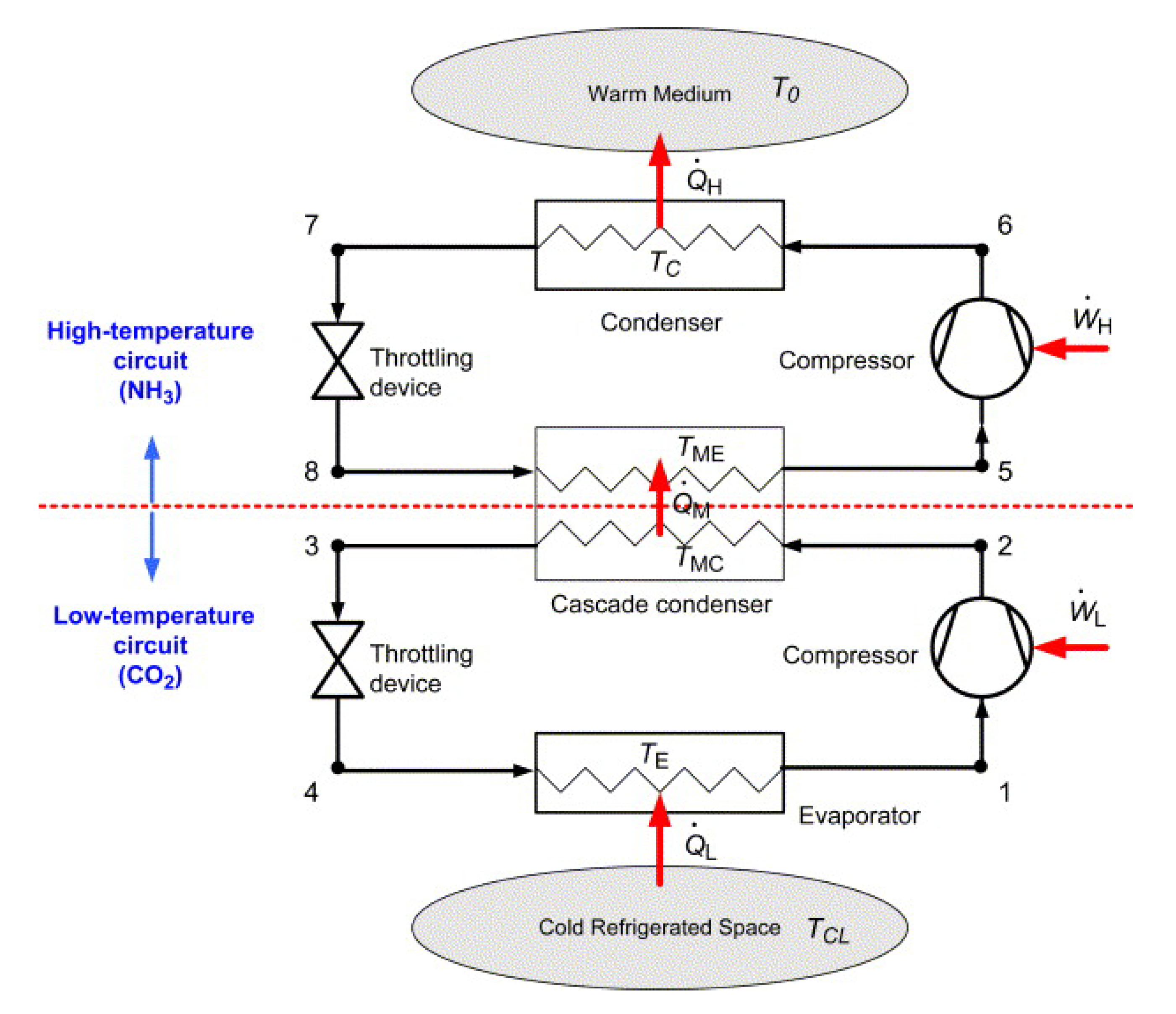
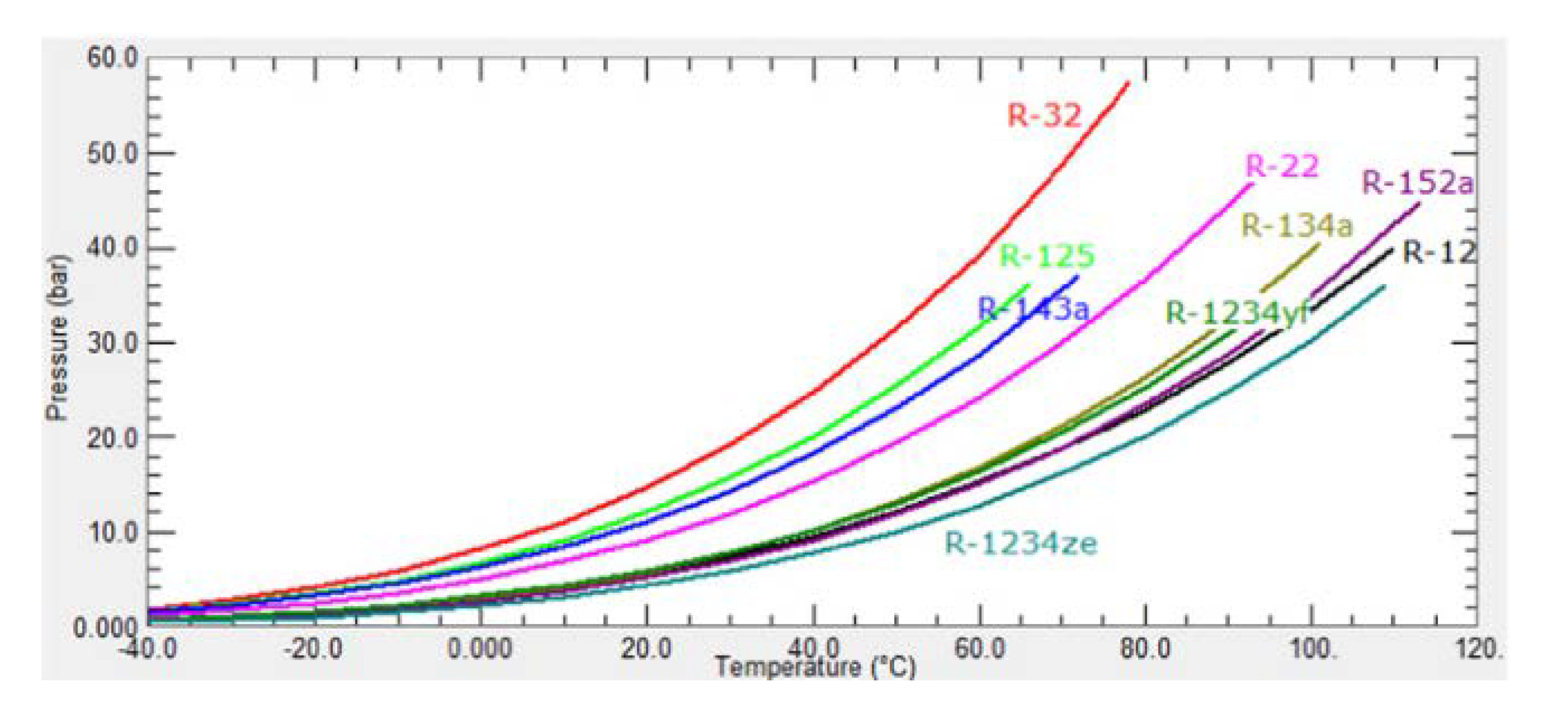
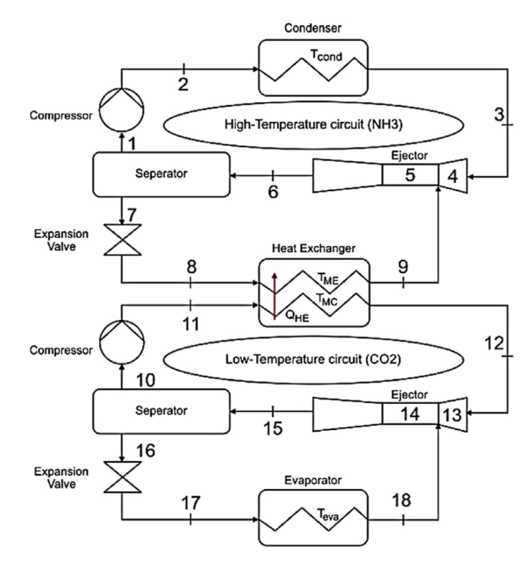
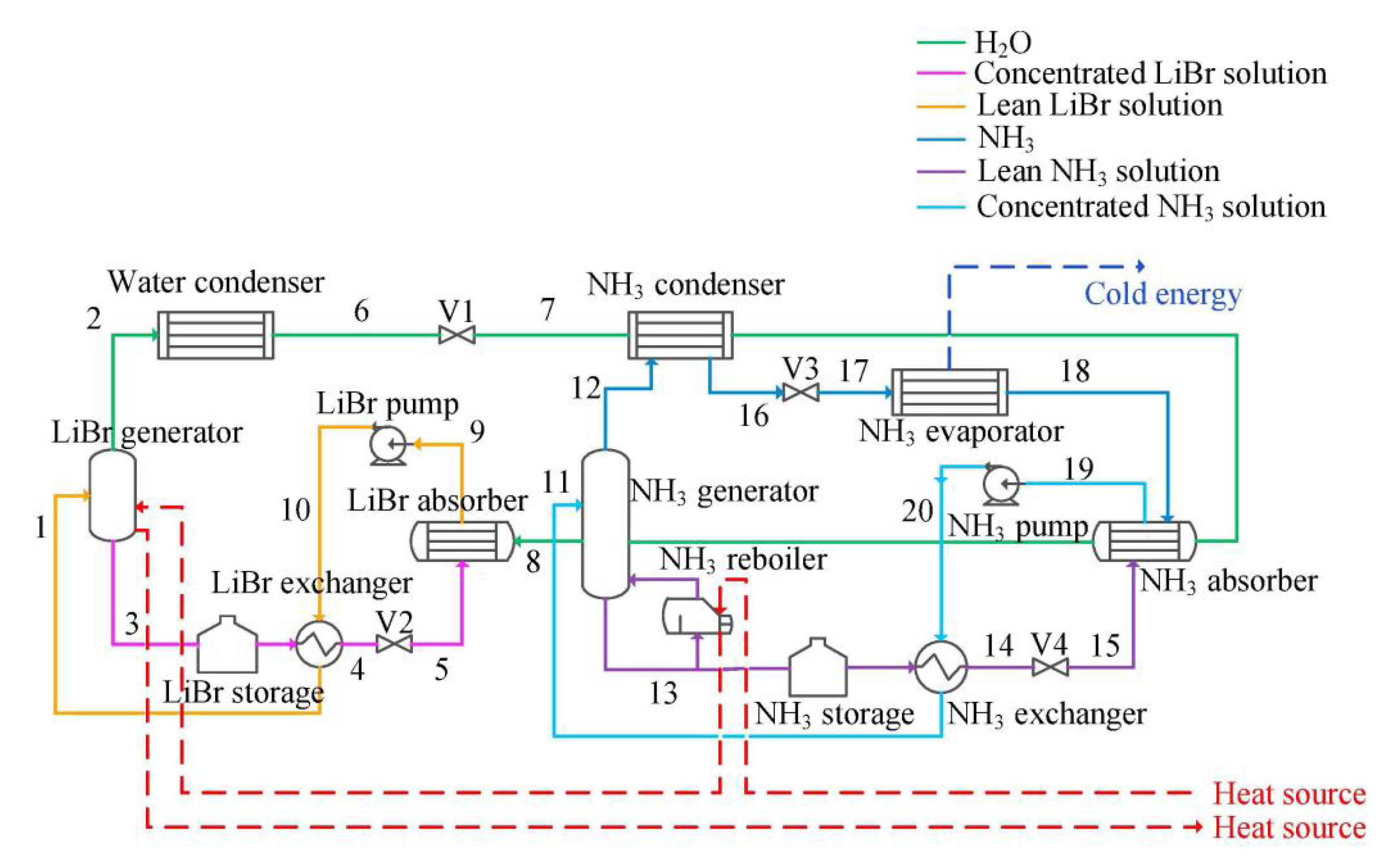
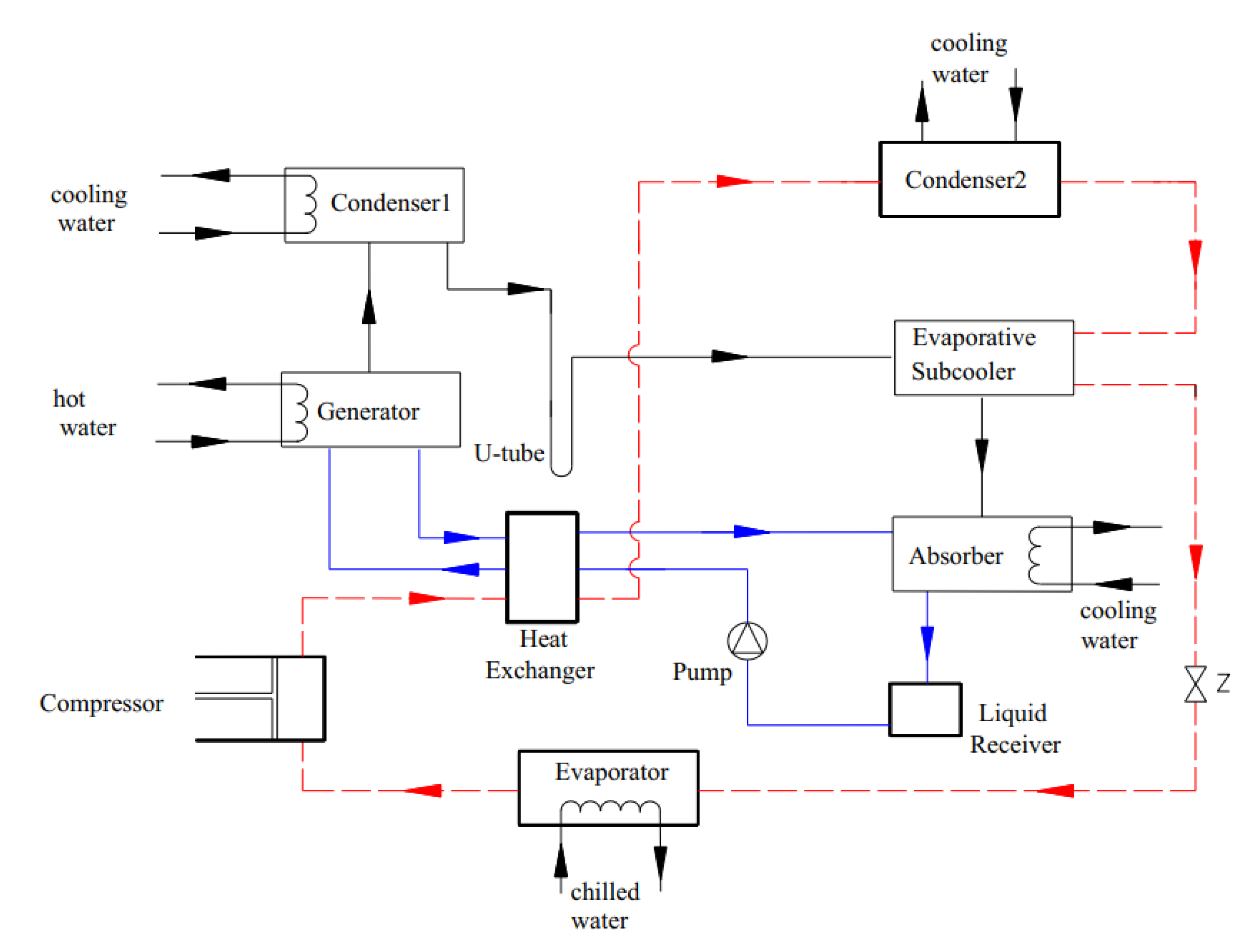
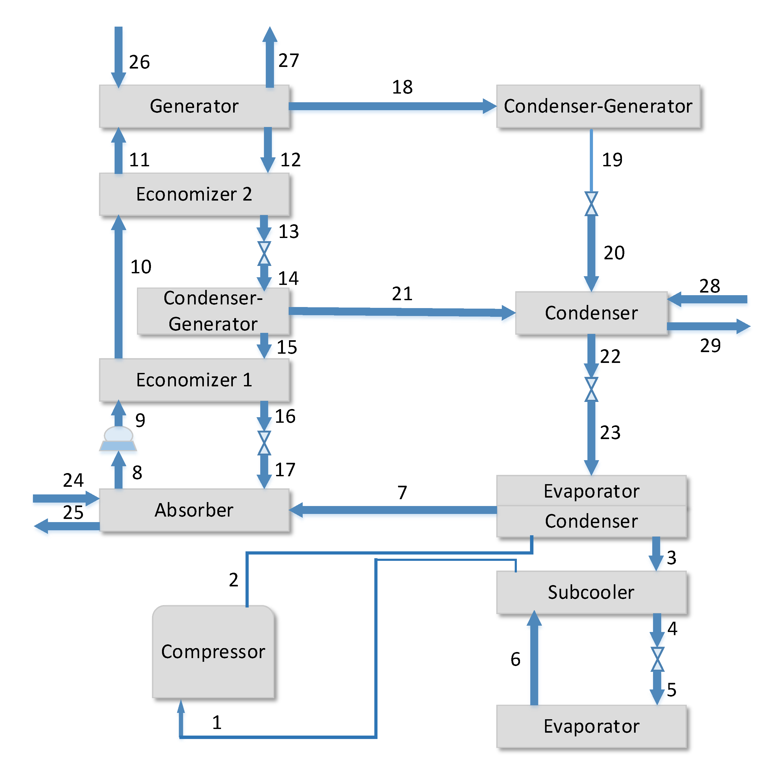
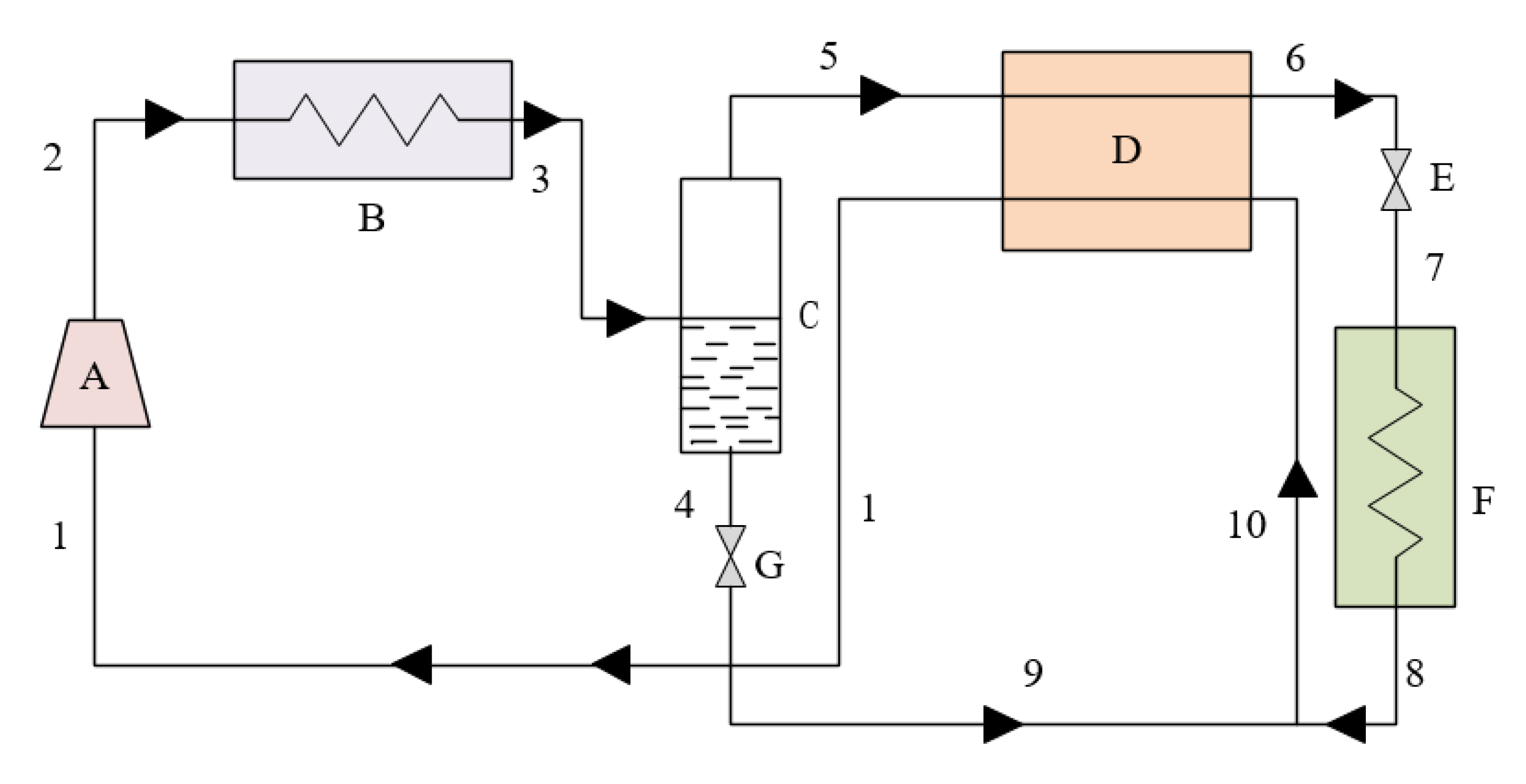
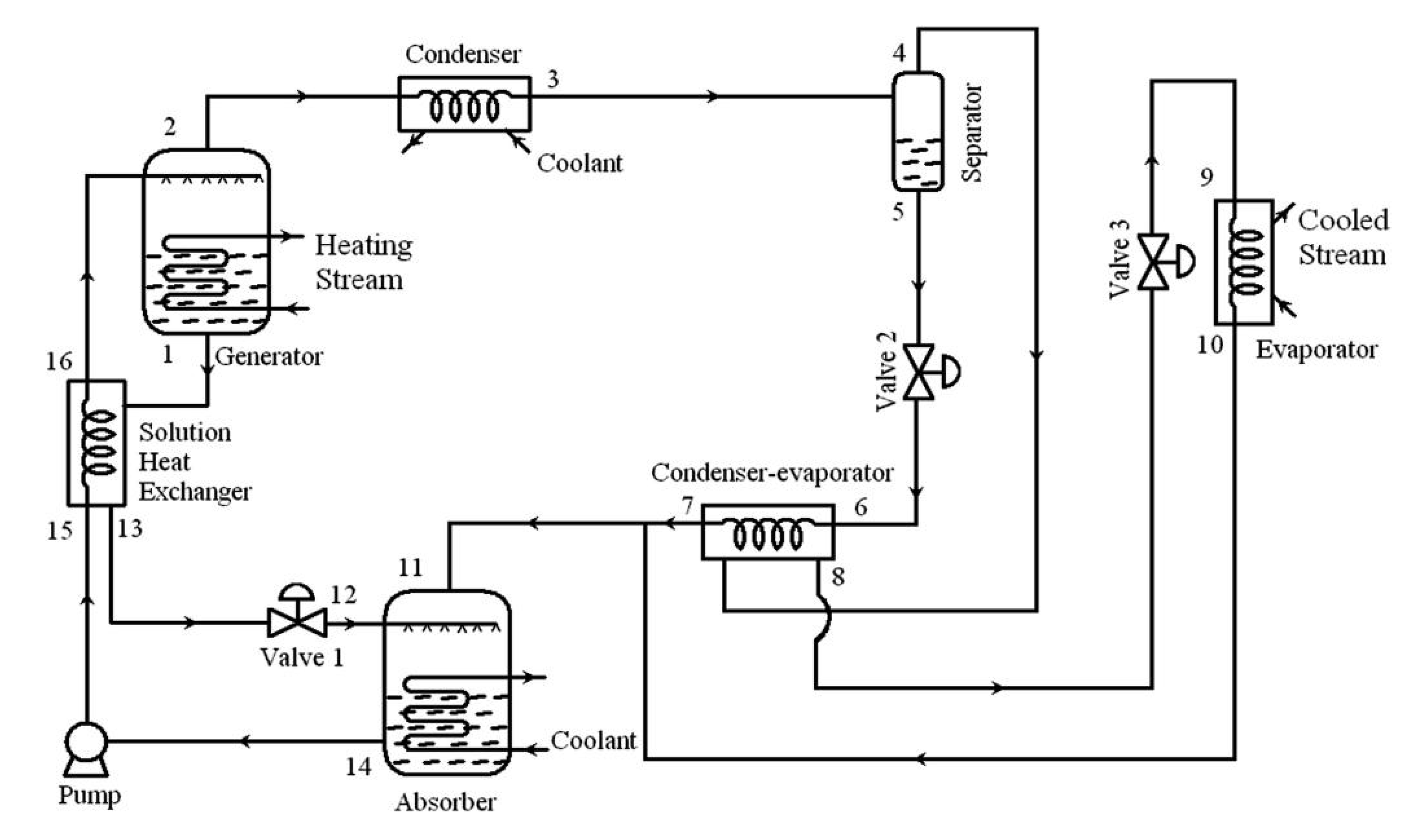
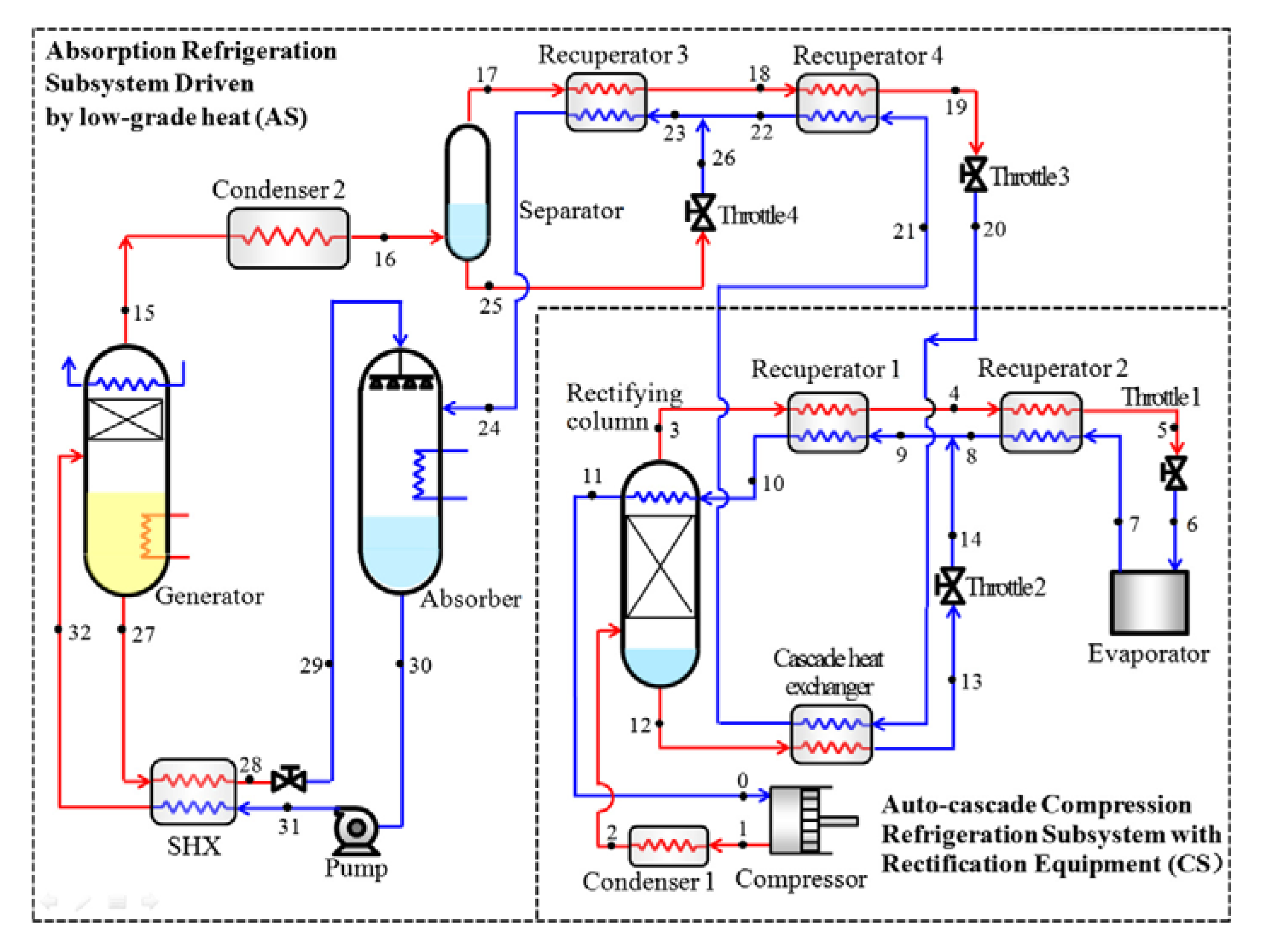
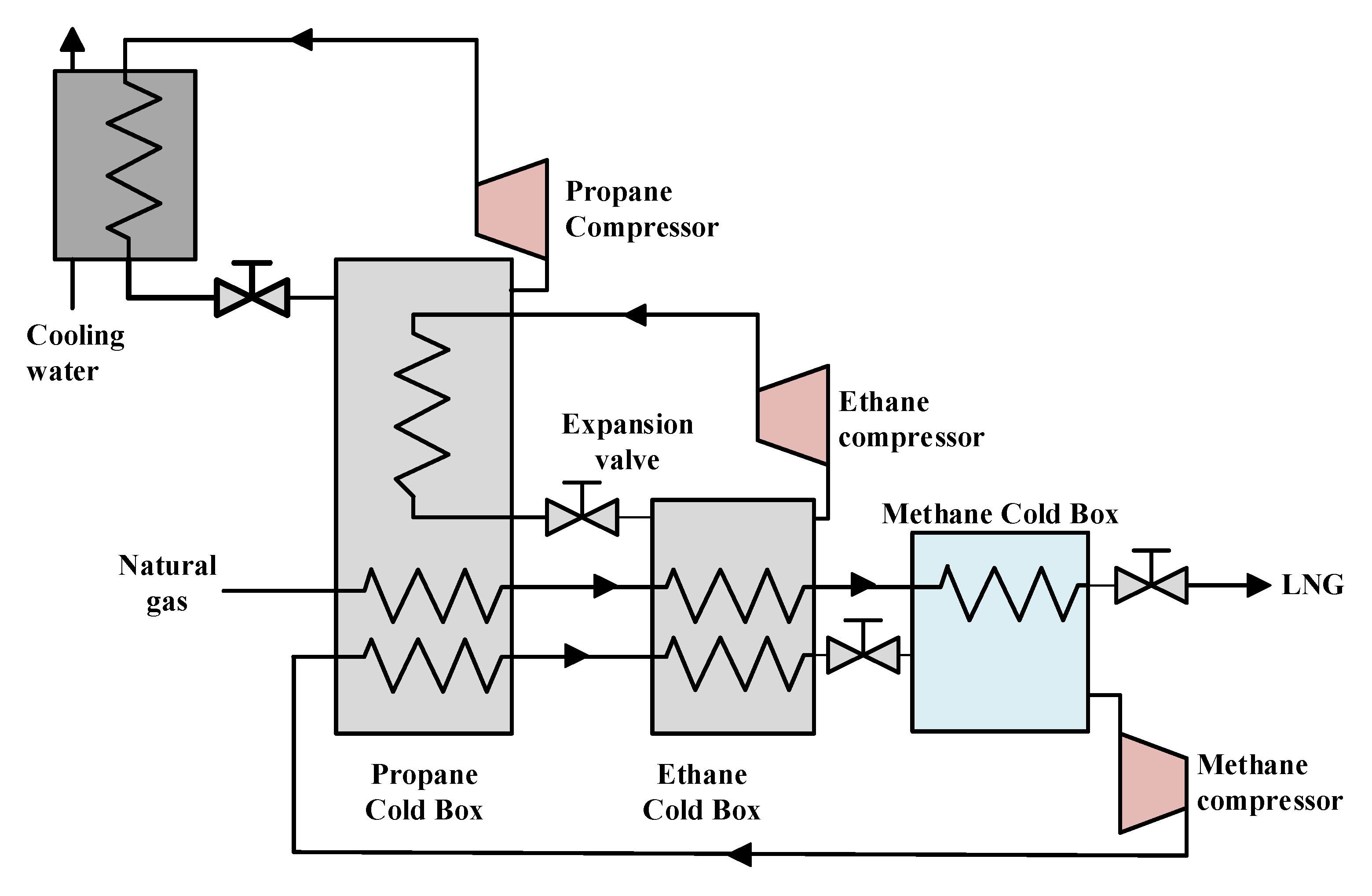
Table 1.
The associated fluids and temperature ranges for the various CRS in the investigations reviewed in this work.
Table 1.
The associated fluids and temperature ranges for the various CRS in the investigations reviewed in this work.
| Cycle Type | Main Working Fluids | Temperature Range |
|---|---|---|
| CCRS | R744, R717 | −60 °C to −80 °C |
| TCRS | C3H8, N2O, N2 | −80 °C to −100 °C |
| CARS | R717, LiBr-H2O | <−40 °C |
| CACRS | R717, LiBr-H2O, R744 | −40 °C to −50 °C |
| ACRS | R23, R50 N2, R170, R290 | <−60 °C |
Table 2.
Standard parameters of various refrigerants reviewed in CRS.
| Refrigerant | ODP | GWP | Tb (°C) | Tcrit (°C) | Pcrit (bar) | Flammability |
|---|---|---|---|---|---|---|
| R744 | 0 | 1 | −78.46 | 31.5 | 73.77 | non-flammability |
| R717 | 0 | 0 | −33.33 | 132.4 | 113.33 | flammability |
| R600 | 0 | 20 | −0.49 | 151.9 | 37.96 | flammability |
| R1270 | 0 | 20 | −47.62 | 92.4 | 45.55 | flammability |
| R161 | 0 | 12 | −37.5 | 102 | 51 | flammability |
| R170 | 0 | 20 | −88.58 | 32.3 | 48.72 | flammability |
| R290 | 0 | 20 | −42.11 | 96.9 | 42.512 | flammability |
| R404a | 0 | 3850 | −46.1 | 72.4 | 36.9 | non-flammability |
| R152a | 0 | 124 | −25 | 113.26 | 45.2 | flammability |
| R23 | 0 | 5.7 | −84 | 25.7 | 48.4 | non-flammability |
| R41 | 0 | 107 | −78.31 | 44.13 | 58.97 | flammability |
| R1234yf | 0 | 4 | −29.45 | 94.7 | 33.82 | flammability |
| R1234ze (E) | 0 | 6 | −18.95 | 109 | 36.32 | non-flammability |
| R1233zd (E) | 0 | 7 | 18.26 | 166.5 | 36.24 | non-flammability |
Table 3.
HFC/HFO Mixtures composition by mass percentage [43]. Reproduced with permission from [Elsevier], Elsevier, 2020.
Table 3.
HFC/HFO Mixtures composition by mass percentage [43]. Reproduced with permission from [Elsevier], Elsevier, 2020.
| Baseline | Mixture | R125 | R134a | R152a | R32 | R744 | R1234yf | R1234ze (E) |
|---|---|---|---|---|---|---|---|---|
| R134a | AC5X | 40% | 7% | 53% | ||||
| ARM-41a | 63% | 6% | 30% | |||||
| D-4Y | 40% | 60% | ||||||
| N13 (R450A) | 42% | 58% | ||||||
| XP-10 | 44% | 56% | ||||||
| AC5 (R444A) | 5% | 12% | 83% | |||||
| ARM-42a | 11% | 7% | 82% | |||||
| R404A | ARM-32a | 30% | 25% | 25% | 20% | |||
| DR-33 | 25% | 24% | 26% | 25% | ||||
| N40 (R448A) | 26% | 26% | 7% | 21% | 20% | |||
| ARM-30a | 29% | 71% | ||||||
| ARM-31a | 28% | 21% | 51% | |||||
| D2Y65 | 35% | 65% | ||||||
| DR-7 | 36% | 64% | ||||||
| L-40 | 10% | 40% | 30% | 20% | ||||
| R410A | ARM-70a | 10% | 50% | 40% | ||||
| D2Y60 | 40% | 60% | ||||||
| DR-5 | 72.5% | 27.5% | ||||||
| HPR1D | 60% | 6% | 34% | |||||
| L41 (R447A) | 3.5% | 68.0% | 28.5% |
© 2020 by the authors. Licensee MDPI, Basel, Switzerland. This article is an open access article distributed under the terms and conditions of the Creative Commons Attribution (CC BY) license (http://creativecommons.org/licenses/by/4.0/).
Share and Cite
MDPI and ACS Style
Pan, M.; Zhao, H.; Liang, D.; Zhu, Y.; Liang, Y.; Bao, G. A Review of the Cascade Refrigeration System. Energies 2020, 13, 2254. https://0-doi-org.brum.beds.ac.uk/10.3390/en13092254
AMA Style
Pan M, Zhao H, Liang D, Zhu Y, Liang Y, Bao G. A Review of the Cascade Refrigeration System. Energies. 2020; 13(9):2254. https://0-doi-org.brum.beds.ac.uk/10.3390/en13092254
Chicago/Turabian StylePan, Mingzhang, Huan Zhao, Dongwu Liang, Yan Zhu, Youcai Liang, and Guangrui Bao. 2020. "A Review of the Cascade Refrigeration System" Energies 13, no. 9: 2254. https://0-doi-org.brum.beds.ac.uk/10.3390/en13092254
Note that from the first issue of 2016, this journal uses article numbers instead of page numbers. See further details here.