Retrofit Decarbonization of Coal Power Plants—A Case Study for Poland


1
Qvist Consulting Limited, Middlesex, Southall UB1 3EP, UK
2
Faculty of Energy and Fuels, AGH University of Science and Technology, 30-059 Krakow, Poland
3
Department of Power Engineering and Turbomachinery, Silesian University of Technology, 44-100 Gliwice, Poland
4
Faculty of Geology, Geophysics and Environmental Protection, AGH University of Science and Technology, 30-059 Krakow, Poland
*
Author to whom correspondence should be addressed.
Energies 2021, 14(1), 120; https://0-doi-org.brum.beds.ac.uk/10.3390/en14010120
Submission received: 12 October 2020
/
Revised: 21 December 2020
/
Accepted: 22 December 2020
/
Published: 28 December 2020
(This article belongs to the Section F: Electrical Engineering)
Abstract
:Out of 2 TWe of coal power plant capacity in operation globally today, more than half is less than 14 years old. Climate policy related to limiting CO2-emissions makes the longer-term operation of these plants untenable. In this study, we assess the spectrum of available options for the future of both equipment and jobs in the coal power sector by assessing the full scope of “retrofit decarbonization” options. Retrofit decarbonization is an umbrella term that includes adding carbon capture, fuel conversion, and the replacement of coal boilers with new low-carbon energy sources, in each case re-using as much of the existing equipment as economically practicable while reducing or eliminating emissions. This article explores this idea using the Polish coal power fleet as a case study. Retrofit decarbonization in Poland was shown to be most attractive using high-temperature small modular nuclear reactors (SMRs) to replace coal boilers, which can lower upfront capital costs by ~28–35% and levelized cost of electricity by 9–28% compared to a greenfield installation. If retrofit decarbonization is implemented globally by the late 2020s, up to 200 billion tons of otherwise-committed CO2-emissions could be avoided.
Keywords:
retrofit decarbonization; decarbonization; climate change; repowering; renewable; nuclear; coal; CO21. Introduction
Power sector emissions represent the largest source of greenhouse gas emissions globally, and coal-fired power stations are the biggest source of emissions within this sector [1]. To avoid the worst impacts of climate change, rapid decarbonization of coal-heavy economies is essential. It is the ambition of this study to assess:
- To what extent existing coal power plant assets may play a role in a future decarbonized power system, either by adding carbon capture, replacing the feedstock to biomass, or replacing the coal boilers with low-carbon energy sources.
- What the most effective retrofit decarbonization options are for the most modern coal units in operation or under construction today.
- Whether such replacements or retrofits makes technical and economic sense, compared to abandoning existing coal plant assets entirely and building a new low-carbon power system from scratch.
In existing decarbonization strategies, two major pathways have been suggested for the future of existing coal power plant equipment:
- Retire the coal power plants and replace their function with a combination of energy efficiency (reducing demand for heat and electricity) and new, greenfield, low-carbon energy production, or
- Maintain the assets and decarbonize them by reducing direct emissions by adding carbon capture or lifecycle emissions by switching to biomass combustion.
Any successful decarbonization strategy for a heavily coal-dependent economy may include some component of both of the strategies above. In this study we assess the potential of these strategies as options in a broader general strategy, which we call “retrofit decarbonization” of coal power units. The definition of retrofit decarbonization used in this study is an umbrella term that encompasses:
- The repowering of a coal power unit with a new low-carbon energy source
- The conversion of feedstock from coal to a sustainable sourced biofuel
- The retrofit installation of carbon capture at a coal power unit
To qualify as a retrofit decarbonization project, the decarbonized plant must fulfil the following objectives:
- Lifecycle emissions lower than 50 gCO2-eq/kWh, in line with what is assessed by the OECD to be the required average power system emissions intensity globally by 2050 in order to meet the 2015 Paris Agreement goals [2] and the local requirement by earlier dates in many countries to achieve national targets (for example in the UK by 2030 [3]).
- Maintaining an annual energy production (electricity and/or heat) of at least 50% of the reference value of the coal unit within the existing site footprint. This corresponds to an areal generation capacity of ~1 MWh/m2/y.
- Not just the power plant site, but existing coal plant equipment, representing at least 5% of original plant capital expenditure (CAPEX), is re-utilized and remains in operation at the retrofit decarbonized plant.
To assess the relative merits of various retrofit decarbonization options, the coal power sector in Poland was used for a detailed case study. Poland’s power sector, responsible for around 50% of its total greenhouse gas emissions, is tightly coupled with the domestic coal sector. Coal power makes up nearly 80% of annual electricity generation and 70% of the available generating capacity [4]. In addition, a quarter of polish heating is provided through district heating networks by combined heat and power (CHP) and heat-only stations that are fueled by coal.
The possible retrofit options that were identified as a part of this study include the following:
- Adding post-combustion carbon capture
- Converting to biomass feedstock
- Converting to natural gas combined cycle (NGCC) with added carbon capture
- Wind power
- Solar photovoltaic (PV) power
- Combinations of wind power and solar PV
- Solar thermal power
- Adding a nuclear reactor heat source
- Adding a geothermal heat source
For options #4–9, IPCC estimates of the median lifecycle emissions are below the threshold of 50 gCO2-eq/kWh [5], whereas for options #1–3, adherence to this criterion is challenging and will need to be proven on a case-by-case basis. Analysis for the potential for options #1 and #2 for the Polish power system is covered in the Supplementary Materials document in Section 2 and Section 3. Direct emissions of NGCCs with CCS can be brought down to ~25 gCO2-eq/kWh with >95% CO2 capture [5]. Thus, if lifecycle methane emissions from the gas supply system can be brought down below 30 gCO2-eq/kWh, NGCCs can meet the requirements of this study, but this option was not studied in detail. As will be described in detail in Section 7.6, Section 7.7, Section 7.8 and Section 7.9, the huge areal power density difference between a typical coal plant and options #4–7 mean they are unable to fulfill the second condition of retrofit decarbonization defined above, since the annual electricity production from the decarbonized site would then drop by at least 96%. In addition, no realistic way was found in which retrofit criterion #3 (re-utilization of equipment) could be fulfilled by technology options #4–6 (wind and solar PV). Assessing the potential of the remaining options #8 and #9, nuclear and geothermal heat source integrations, is therefore the main focus of this article.
2. Research Method and Paper Structure
This research was carried out using a combination of literature review, qualitative research, as well as quantitative comparative analysis. The structure of this paper is as follows:
- In Section 1 (Introduction), we introduced and defined the concept of “retrofit decarbonization” of coal power plants and briefly presented nine main possible technical options.
- In Section 2, we describe the structure of this analysis and research.
- In Section 3, we present a literature review and overview of the present status of research and implementation of the technical options that were identified for retrofit decarbonization.
- In Section 4, we present the likely remaining carbon budgets for different global warming targets (below 1.5 °C and 2 °C, respectively) and analyze what implications these budgets have for the future operation of existing and planned coal power plants. The analysis in Section 4 illustrates the need for existing and planned coal power capacity to be either scrapped ahead of its useful technical life or to be retrofit decarbonized.
- In Section 5, we analyze the remaining useful life and economic value of existing coal power plant equipment, which determines the overall potential for retrofit decarbonization of any kind.
- In Section 6, we determine the physical footprint of existing coal power plants. As a condition of the analysis in this paper, the retrofit decarbonized plant must fit inside the original site boundary of the coal plant that is to be decarbonized.
- In Section 7, we analyze the physical footprint requirements of each of the nine retrofit decarbonization technology options to determine whether sufficient annual energy production is possible on-site for the plant to qualify as a retrofit decarbonization option (criterion #2 in Section 1). On the basis of this analysis, four out of the nine original technical options are discarded from further analysis.
- In Section 8, we introduce the technical characteristics of the coal power plant fleet of Poland, including the age distribution, size of units, steam parameters, and applications. From this analysis, existing Polish coal plants are grouped in to three major categories. For each category, we define one specific representative coal unit to use for more detailed analysis.
- In Section 10 and Section 11, we present and analyze in detail the prospects of retrofit decarbonization of coal plants in Poland using high-temperature geothermal energy and nuclear energy, respectively.
- Finally, in Section 12, we summarize the results and conclusions, comparing all of the studied options for retrofit decarbonization in terms of economics and the overall potential scale of possible implementation both in Poland and globally.
3. Literature Review
Our extensive literature search did not yield any previous studies that evaluate and compare a wide range of options for retrofit decarbonization of coal power plants. Out of the nine technical alternatives defined in the introductory section, several have however been studied individually. Numerous existing studies have analyzed the addition of post-combustion carbon capture (option #1), converting to biomass feedstock (#3), switching to combined cycle natural gas with carbon capture (#3), and integrating solar thermal power (#7). Options #1, #2, and #7 have also seen real-world implementation.
Re-utilization of coal power plant assets as a general strategy has been gaining traction in the last two decades primarily through the conversion to, or addition of, natural gas and biomass fuel. Such conversions are typically referred to as “repowering” [6]. The most common form of repowering is the conversion from coal to natural gas, often through “heat recovery repowering”, which re-uses the entire existing coal plant steam and heat rejection systems [7]. In such cases, the coal boilers at the plant are decommissioned and replaced by natural gas turbines and a heat recovery steam generator [8]. In the United States between 2011 and 2019, a total of 104 coal-fired plants converted the steam boiler to burn other fuels, most commonly natural gas (86 out 104 units representing 14.3 GWe of capacity), although some were configured to burn petroleum coke (a refinery by-product) or biomass (in the form of waste materials from paper and pulp production, or solid wood waste) [9]. While none of the coal-to-gas conversions so far have featured the addition of carbon capture, the general technology option of NGCC plants with carbon capture has already been demonstrated at small scale (for example the 40 MW slipstream capture at Bellingham NGCC) and has been the subject of extensive research over many years [10]. The main other type of repowering that is becoming increasingly popular, particularly in the United Kingdom, Germany, and the Nordic region, is the conversion (partial or full) from coal to biomass. A recent survey identified 21 units representing 7 GWe of coal capacity outside of the US that have undergone full biomass conversions since 2005 [11,12].
At least three small “solar-coal hybrid” plants, in which solar thermal collectors are used to augment the feedwater heating of a coal power plant, have been in operation so far [13]. While these projects and supporting studies have proven that solar thermal integration can lower the emissions intensity of coal power plants, impacts are typically limited to emissions intensity reductions of a few percent, and option #7 does therefore not constitute a realistic full retrofit decarbonization option.
Nuclear repowering of coal power plants has been mentioned as an idea previously [14], but we were unable to identify any published study on the topic. Nor did we find any previous studies that have examined the integration of geothermal heat sources to an existing coal power plant. Since these new ideas are introduced in this paper, they are the main focus of the analysis in this paper and are presented in greater detail, while other technical options are evaluated either in the Supplementary Materials document (options #2–3) or are discarded on the basis of the general criteria for retrofit decarbonization set out in the introductory section (options #4–7).
4. Carbon Budgets and the Future of Unabated Coal Power
Limiting global warming requires constraining the total cumulative global anthropogenic emissions of CO2, that is, staying within a total “carbon budget”. In 2018, the Intergovernmental Panel on Climate Change (IPCC) published a special report on limiting global warming to 1.5 °C, which provides best-estimates of the remaining total carbon budget to reach this target [15]. Using global mean surface air temperature (GSAT) gives an estimate of the remaining carbon budget of 580 GtCO2 for a 50% probability of limiting warming to 1.5 °C above pre-industrial levels globally, and 420 GtCO2 for a 66% probability. Alternatively, using global mean surface temperature (GMST) gives estimates of 770 and 570 GtCO2, for 50% and 66% probabilities of <1.5 °C respectively. Lowering the climate mitigation ambition to below 2 °C warming increases the carbon budget estimates to 1170–1500 GtCO2 (GSAT, 66% & 50% probability) and 1320–1690 GtCO2 (GMST, 66% & 50% probability).
In the time that has passed since the carbon budget of the 2018 IPCC report was defined (at the end of 2017), the budget has been reduced by a further estimated 36.6 GtCO2 in 2018, 39.6 GtCO2 in 2019 [1] and a likely ~35 GtCO2 for the full year of 2020 (estimated from modelling in ref. [16]), for a cumulative further budget reduction of 111 GtCO2 from the end of 2020. Climate change mitigation scenarios have previously allotted a median ~14% of the remaining carbon budget for electricity generation [17]. Combining the IPCC-calculated 1.5 °C warming carbon budget range, the reductions in budget that have happened since its publication and the typical power sector allocation of total emissions gives a rough estimate for the remaining power sector carbon budget as defined in Figure 1.
Most climate mitigation pathways also include a quite speculative role for bioenergy with carbon capture and storage (BECCS) as a future negative emissions source within the power sector. The median value from the scenarios surveyed by Pfeiffer et al. [17] include an amount of BECCS generation that would remove ~110 GtCO2 from the atmosphere by the end of the 21st century, thereby increasing the carbon budget for the power sector by this amount. Thus, with generous assumptions (<2 °C warming with 50% probability, GSAT), allocating 14% of the total budget to power generation and giving 110 GtCO2 emissions credit to future BECCS implementation, an absolute ceiling for cumulative < 2 °C power sector emissions budget post 2020 of 330 GtCO2 can be defined, which corresponds to ~20 years of current power sector emissions (14 GtCO2/year in 2018 [18]). If we do not credit the carbon budget with negative emissions from future BECCS and use the 66% probability GMST-value for <2 °C warming, maintaining current power sector emissions would consume the carbon budget in 10 years. On the extreme low end, 66% probability of <1.5 °C warming with no credit to BECCS, the remaining power sector carbon budget is equivalent to just three years of current power sector emissions.
Regardless of whether the power sector carbon budget ceiling is set at the equivalent of three, 10, or 20 years of current emissions, there is widespread scientific agreement that continued unabated emissions from the operation of existing and planned coal power plants is incompatible with the carbon budgets that limit warming to below either 1.5 °C or 2 °C [19,20,21,22]. Already committed emissions, meaning the cumulative emissions that could result from coal power capacity currently in operation, and new capacity under construction, exceeds the emissions that can reasonably be allotted to coal power generation in available carbon budgets. Each newly constructed 1 GW of coal plant capacity risk committing to an additional 200 ± 100 million tons of cumulative CO2 emissions (calculations details are available in the Appendix A of the Supplementary Materials).
In 2020, the world has 2047 GWe of operational coal power capacity and at least 190 GWe under construction, for a total applicable near-term capacity of 2237 GWe [23]. A more recent report (June 2020) finds even higher values than previously expected for the Chinese coal expansion during 2020, with 98 GWe in construction and a further 152 GWe in planning [24], indicating that the global value of 190 GWe might be a conservative estimate. The global effective age of coal power plant capacity (when including capacity currently under construction) is approximately 18 years based on calendar time, calculated with data from Global Coal Plant Tracker. Using the simple method described in Appendix A of the Supplementary Materials, we calculate global committed emissions from these coal plants to be 294 ± 120 GTCO2. The International Energy Agency estimates this figure at 328 GTCO2 [25], while analysis by The Global Coal Plant Tracker (endcoal.org) reached a value of 235 GTCO2 [26]. Tong et al., include operating as well as proposed plants and calculate 357 GTCO2 with a sensitivity span of 244–479 GTCO2 [27]. Edenhofer et al. [28] and Pfeiffer et al. [29] also include proposed plants and reach values of 340 and 430 GTCO2, respectively. These values can be compared to the span of total remaining estimated power sector carbon budget of 40–220 GTCO2.
According to the analysis of Pfeiffer et al. (2016) [30], if other sectors of the economy outside of the power sector continue to fail to meet very rapid emissions reductions consistent with a <2 °C warming pathway, even a premature retirement of all global fossil fuel electricity capacity today would not be sufficient to provide a 50% probability of limiting temperature increases to 2 °C. Analysis by Cui et al. [22] state that “no country can stay on track with the long-term Paris goals without accelerating coal retirement along with canceling new projects”. While the above analysis shows that global unabated coal power capacity will need to be decommissioned or repurposed on a greatly accelerated schedule, with existing plants not allowed to operate to their full technical lifetimes, the phaseout will not need to happen at the same rate everywhere [30]. Wealthier nations, who have caused an outsized proportion of cumulative historic global CO2 emissions compared to the size of their populations and are in a more favorable economic position to make large climate-related investments, are typically subject to more rapid emissions reduction pathways. For example, in analysis by Climate Analytics, all European Union coal power plants will need to be phased out before 2030 [31]. The same analysis indicates that the country chosen for the case study here, Poland, needs to phase out (or repurpose) nearly all of its unabated coal power capacity already by 2025.
5. The Lifespan and Value of Coal Power Plant Equipment
The cost-effectiveness of options for retrofit decarbonization for coal plants as well as the financial implications of stranding existing assets depend critically on the estimation of the remaining useful life of the equipment, which can be defined as the difference between the “effective age” and the maximum useful service life. The “effective age” of a coal plant at any point in time can be in principle be calculated only if the condition of major plant components is well known. Its value can be assumed to increase with calendar time for the first ~15–20 years of the plant’s life, before any major and costly components are changed out. Modernisations and renovations of major aging components past this point can halt the progression of effective age and even temporarily reduce its value even as calendar time passes. A 25-year-old plant in calendar time with many major components replaced or refurbished might have an effective age of 15 years, and therefore at that point in time have more remaining useful life (and more economic value) than a 20-year-old plant that has not yet been refurbished. This plant-level detail is inevitably missed when conducting global or regional analysis, if the effective age is only approximated by the calendar time elapsed since the plant originally started operation. In terms of the potential for re-using equipment for retrofit decarbonization, one need not only know a more precise value for the plant effective age, but also the condition of different parts of the plant, some of which can be re-used, others that will be scrapped. This is the main reason why this study narrowly focuses specifically on one economy (Poland) for detailed analysis, which allows for a more precise determination of the real condition of the coal power plant fleet.
The determination of the value of the maximum possible lifetime of a coal power plant depends on how the term is defined and may fall into the category of the ancient paradox and thought experiment “The Ship of Theseus” (“The Ship of Theseus” is a thought experiment that raises the question of whether an object that has had all of its components replaced remains fundamentally the same object. The concept has been discussed in Western philosophy for more than 2000 years [32]). Any individual component of a power plant has a finite operational lifetime, which is heavily impacted by the quality and frequency of maintenance but nevertheless can be determined within a reasonable range [33]. Plant lifetime limits can typically not be inferred from plant retirement data, since there is a wide range of reasons why coal plants have retired apart from physical causes. These include changing regulations related to emission standards, rising prices for coal, and falling whole-sale market prices for electricity. Rode et al. [34] studied the physical life of US power generating assets from detailed datasets over the period 1900–2014, to determine mortality curves. Defining the “lifetime” as the calendar age at which more than half of the capacity of a specific type of power plant is retired, they found a value of 70–75 calendar years for coal plants that started operation in the 1930s and 40s. Cycles of increasingly strict or lenient interpretations of air pollution regulations have influenced whether power plant owners use maintenance and refurbishment to prolong the plants’ physical lives, or withhold such investment and retire the plants instead. The IEA defines an upper range of coal power plant lifetime of 90 years [25], while analysis by the National Renewable Energy Laboratory (NREL) limits the lifetime of larger coal units to 75 years [35]. However, these lifetimes assume that most of the equipment at the plants is refurbished or replaced entirely at least once, since very few individual components can be expected to last this long in continuous operation. Based on the 270 cost-categories presented for subcritical and supercritical coal power plants in ref. [36], the capital cost breakdown of relevance to retrofit decarbonization of a hypothetical new 550 MWe subcritical pulverized coal boiler plant is given in Figure 2.
Varying levels of integration and re-use of the existing equipment will enable varying degrees of retained value (avoided stranded costs) and avoided greenfield costs for any new low-carbon energy source that is used for the retrofit decarbonization. The cost share fractions of Figure 2 relate only to a coal power plant unit, so they cannot be used to assess the cost savings compared to greenfield for a new power source. Apart from the coal-related equipment, the most important components are the steam turbogenerator systems, condenser cooling system, and electrical equipment. The lifetime of this equipment is estimated at 35–50 years with proper maintenance. According to ref. [37], the expected lifespan of steam turbines and associated heat exchangers with a capacity of 50–300 MW and steam parameters of 13–24 MPa is 220,000 h, which with a typical coal power plant capacity factor means roughly 40–45 calendar years, but this value changes with different operational characteristics [38]. Gas-insulated switchgear equipment is expected to last “at least 40 years”, and according to ref. [39], “no generic life limiting mechanisms have been reported so far”. Transmission cables and larger power plant cooling towers have expected lifetimes exceeding 50 years, as evidenced by the large number of thermal power plants still in operation approaching or exceeding this age with their original cooling towers and grid connection and cables.
Compared to very early retirement, re-using non-coal-related auxiliary buildings and electrical equipment, turbogenerators, cooling water systems, cooling towers, and pumphouses can thus avoid the stranding of up to 40% of the initial investment at a new coal plant. Additionally, major coal power stations are connected by high-voltage AC transmission lines, in Poland either at 220 kV or 380–400 kV. A “grid connection equipment cost” of €190/kW for coal plants is assumed in NREL modeling studies, equivalent to ~€60 million for a 500 MW connection. The cost of a new high-capacity transmission line is on the order of €2000–3000/MW/km [40], or about €50 million for a 500 MWe connection spanning 40 km. These costs, on the order of €100 million for a 500 MWe plant, would also have to be borne by any greenfield powerplants sited away from existing transmission grid connections, but can be avoided entirely at brownfield retrofit sites.
The overnight capital costs of new coal power plants outside of China and India lie in the range €2600–€6300 per kWe [41,42]. For China and India, costs are more likely in the vicinity of €1000/kW [43]. Using data from the Global Coal Plant Tracker, we estimate conservatively that around 1300 GWe of coal power units globally could be applicable for retrofit decarbonization by 2030. Applying a capacity-weighted average cost of €1500/kW for the coal plants that are eligible for retrofit decarbonization in 2030 and applying a linear depreciation schedule to 40 years with an average effective age of 15 years at that point, the potentially stranded value (as measured from cost), if these assets are abandoned, is ~€1200 billion. Re-utilizing rather than stranding 40% of the value of these investments for retrofit decarbonization can thus be expected to save decarbonization efforts at least €500 billion.
6. The Physical Footprint of a Coal Power Plant or Unit
Coal power production equipment (such the coal boiler buildings, the steam turbine and generator buildings, and the switchyards) are of a fairly uniform in size for a given power level at any plant. A description and illustration of a typical coal power plant layout is given in the Supplementary Materials Section 2. It is still very difficult to give one indicative normalized number for the amount of direct land area taken up by a “typical” coal power plant with a given capacity, as values differ greatly from site to site. The main determining factors for the plant footprint are:
- Rural, semi-urban, or urban siting
- Size of on-site coal and ash storage piles
- Open (direct) cooling or the use of cooling towers
Plants that use natural draft cooling towers and cooling ponds, sited in rural areas with large on-site storage of both coal and ash, can take up many times more space than an equivalent semi-urban sited plant with a layout aimed at minimizing land use. Literature values for the normalized footprint (in m2/MW) differ by up to a factor of 30. Studying the results of eight different reports focused primarily on coal plants in the United States (ref. [44,45,46,47,48,49,50]) yielded a combined average of approximately 2700 m2 per MW, or a total site area of 2.7 km2 for a 1000 MW coal power plant. For the 303 coal-fired power units, we have assessed in this study in Poland; no central database or report detailing site sizes was found. To assess the footprint of coal plants in Poland, a number of plants were mapped out using online mapping tools, which yielded values in the lower range of the literature review results. The smaller normalized footprint is likely due to a combination of a higher utilization of ash (which means smaller on-site ash storage) and the higher fraction of semi-urban-sited coal power plants in Poland as compared to the United States. Typically, the larger the capacity of a coal plant becomes, the smaller the land use requirement per MWe, since much of the equipment can be shared between several coal boiler units. In our assessment, the total land use of Polish coal power plants with a capacity above 50 MWe lies in the range of 500–2000 m2/MWe, with some large-capacity units approaching the lower limit of this range.
7. The Physical Footprint of Retrofit Decarbonization Options
7.1. Introduction
The third requirement for retrofit decarbonization described in Section 1 states that the new decarbonized plant should be able to produce at least half the amount of annual electricity of the original plant. The uppermost value in the range of coal plant footprints is 2000 m2/MW, while the very worst operating coal plants applicable for retrofit decarbonization run at an annual capacity factor of about 45%. The retrofit decarbonized plant would therefore have to be able to achieve at the very minimum an areal power production density of ~1 MWh/m2/y.
7.2. Adding Carbon Capture
A coal power plant site can be directly decarbonized to a large extent by adding carbon capture equipment, for which there is adequate room available at nearly all existing larger coal power stations. Based on our assessment of the added footprint for CCS equipment at Boundary Dam power station in Estevan, Saskatchewan, Canada, and the Petra Nova project at the W.A. Parish coal power plant in Texas, USA, an indicative additional space requirement for the addition of capture equipment is approximately 10–20% of the original plant area [51]. Additional land needs to be made available on the site for a capture unit building, a CO2 compression building and, if needed, additional scrubbing and heat rejection systems. The total area requirement, including separation distances between buildings, is on the order of 50 m2/MW. In all but the most cramped site layouts, this equipment can be installed without needing to increase the overall site area. Since the capture equipment requires energy (both steam and electricity), the net output of the site is reduced if the coal plant itself is used to power the capture equipment. The impact on net output is a reduction on the order of 17–25% of annual electricity generation [52,53,54]. Another option is to add a new combined cycle natural gas plant to an existing coal power plant specifically to run the capture equipment. However, adding both a natural gas plant and capture equipment may not be possible at all coal power stations without expanding the overall site area.
7.3. Converting to Biomass Feedstock
A biomass conversion, meaning that the boiler units are reconfigured to combust only biomass and no coal, typically has little impact on the power plant site footprint, and would re-use most of the existing site equipment. Depending on the type of biomass feedstock, the site may need to add biomass storage silos, and accompanying new receiving and transfer infrastructure.
7.4. Converting to Natural Gas and Carbon Capture
A natural gas plant takes up significantly less land area than an equivalent coal power plant due to the omission of spacious coal and ash handling areas. Natural gas arrives in a pipeline and leaves no ash behind when combusted. It is therefore highly space efficient. New or converted natural gas boilers with added carbon capture can easily fit in to any existing coal power plant, and the net site annual power output can be maintained even with the addition of capture equipment. However, only coal plants relatively close to an existing natural gas transmission pipeline are applicable for this type of retrofit.
7.5. Switching Out Coal Boilers for Nuclear Reactors
A thorough review of the land required for nuclear reactors is available in the Supplementary Materials, Section 6.3. Nuclear power plants require less than 500 m2/MW of space, and typically operate at significantly higher capacity factors than coal power plants due to the lower marginal production costs. Since equal or more nuclear generating capacity can be placed on site, one can expect a maintained (or more likely higher) annual power generation from the site after making the conversion than before.
7.6. Wind Turbines
The direct physical land footprint of onshore wind turbines is very small, and the area in between turbines can be used for other purposes. However, siting wind turbines too close together has a number of negative consequences resulting from the turbulent nature of the air exiting turbines and entering adjacent turbines. Consequently, wind turbine manufacturers and wind farm designers typically recommend separation distances of seven rotor diameters for turbines in line with the prevailing wind direction and five rotor diameters for turbines abreast. The latest satellite-observation based studies indicate an areal power density of approx. 2.7 MW/km2 for onshore wind farms, equivalent to a total normalized footprint, including spacing between turbines, of 370,000 m2/MW [55]. Given the spacing requirements of wind turbines and the typical capacity factors of onshore wind (25–45%), it is not possible to achieve an annual electricity generation of more than ~0.5% of a typical coal plant electricity generation (or ~0.01 MWh/m2/y) by replacing it with a wind farm of any kind on the same site.
7.7. Solar Photovoltaic Panels
According to satellite-observation-based studies, a typical utility-scale solar PV farm has an areal power density of approx. 24 MWAC /km2, equivalent to a total land use of 33,000 m2/MWAC (solar panels produce direct current (DC) power, which is then inverted to alternating current (AC) to be fed to the electricity grid. Typically, the installed panel power (DC) is higher than the installed inverter capacity (AC) by a factor of 1.3) [55]. The expected capacity factor of utility-scale solar PV farms in Poland is approx. 12%, or about one quarter that of an average coal power plant [56]. The resulting annual power output from a solar PV farm at a coal power plant site is therefore limited to ~1.6% of the coal power plant output (or ~0.03 MWh/m2/y). For mine-mouth lignite coal plants, it could also be possible to convert part of the adjacent coal mine into an artificial lake, on top of which a floating solar PV farm could be installed. This would substantially increase the total area and generation from solar PV at the site but could still not bring the figures within the criteria defined in Section 1.
7.8. Onshore Wind + Solar Photovoltaic Panels
Given the very low direct overground footprint of wind turbine foundations and the fact that solar PV panels mounted close to the ground do not interfere with the wind resource, more capacity and generation can be put at a coal power plant site by combining the two resources. Depending on the location of the wind turbines, access roads may take up some of the space otherwise available for solar panels. To reflect this and the direct land taken up by the wind turbine foundations, the solar PV density was reduced by 20% from 24 to 19 MW/km2 in this example. Combining both solar PV and wind turbines may increase the expected annual generation up to a maximum of ~1.8% of the output of the existing coal power plant (or ~0.036 MWh/m2/y).
7.9. Concentrating Solar Power
According to the US National Renewable Energy Laboratory (NREL), the direct average land footprint of CSP plants without storage is 31,200 m2/MW, while total land use is 40,000 m2/MW [57]. The expected annual capacity factor for a CSP plant without storage is ~12% in Poland, or about one quarter that of an average coal power plant [57]. The resulting maximum annual power output from a CSP plant at a coal power plant site is therefore ~1.7% of the coal power plant output (or ~0.034 MWh/m2/y).
7.10. Geothermal Power
At a geothermal power plant, a number of relatively small-footprint wells are dispersed throughout a large resource area. The spacing of wells depends on the porosity and permeability of the reservoir rocks. The density of wells in existing geothermal fields across the world ranges from one well per 40,000 m2 to one well per 160,000 m2 [49]. On average, about 2000 m2 per well is required for access roads and the pipeline system that delivers hot water or steam. Given the low geothermal temperature gradient and lack of shallow-depth hot spots in Poland, the only feasible geothermal power plant technology for producing electricity using a steam cycle at large scale are enhanced geothermal systems (EGS) with deep drilling technology that utilizes hot dry rock as the energy source. From available data, such a system can in theory reach a footprint as energy-dense as 4000 m2/MW [49], although other more recent estimates puts this number at ~20,000 m2/MW for any plant above 100 MWe [58]. The most optimistic number (4000 m2/MW) would mean a peak power output capacity corresponding to up to 50% of that of the existing coal power plant could fit within the same site. Geothermal plants operate at an industry-average annual capacity factor of ~70%, but individual plants can reach well above 90%. Assuming an annual capacity factor of 80%, the resulting hypothetical annual power output from a geothermal power plant at a coal power plant can therefore reach up to 90% of the coal power plant output on the same site (or ~1.75 MWh/m2/y).
7.11. Other Low-Carbon Energy Sources
Hydroelectric, tidal, and wave power plants require adequate water-energy resources that are not available for exploitation at Polish coal power plants. They are thus not applicable technologies for any type of coal plant conversion, including re-using just the site itself. Biogas, if it could be sourced in sufficient quantities at acceptable cost, would function in a similar way to natural gas but without the need for carbon capture. Offshore wind farms could hypothetically make some use of the available switchyard and grid transmission connection at a coal plant if they would be located directly adjacent to a site. There does not appear to be any suitable sites for this in Poland. In practice, all offshore wind farms of >200 MW scale include offshore substations and transfer the power onshore through high-voltage direct current (HVDC) cables.
7.12. Summary
It is clear from this survey that adding carbon capture equipment is feasible within the existing site boundary, and one could in many cases maintain current annual output by adding an external heat and power source to run the capture equipment, such as a combined cycle natural gas plant. Conversions to biomass feedstock, natural gas with carbon capture or adding a nuclear heat source would allow the site to maintain or even increase existing capacity and annual generation. Advanced deep-drill enhanced geothermal systems may, at least in theory, be developed that could cover up to 90% of the annual generation of a smaller coal power plant or unit within the same site boundary. Due to the large difference in footprint compared to thermal power sources, solar and wind “conversions” would reduce the site annual power output by 98% or more. It is highly likely that many existing coal power plant sites will become hosts to new solar PV farms and wind farms in the future as a part of decarbonization efforts. One may refer to such developments as “conversions” or “decarbonizations” of coal plants, but in reality, it essentially amounts to the removal of a coal power plant with a small amount of replacement generation added back in. If the capacity and annual generation from the coal power plant was needed for the power system, the actual replacement for this generation and capacity would still have to be found in other locations. A summary of the land requirement implications is given in Table 1.
As described in the introduction, decarbonization through adding carbon capture and converting to biomass or natural gas feedstock are not only well studied options but are also already implemented and proven. Therefore, the focus of this study is primarily on the potential for coal power plant conversion to nuclear and geothermal heat sources, which appears to have potential as new decarbonization pathways, and which, based on an extensive literature search, do not appear to have been studied to date.
8. The Existing Polish Coal Power Fleet
8.1. Age and Size of Units
The current Polish power and heat sector included in this study consists of 303 larger coal units with a combined installed capacity of 33.3 GWe. All data were collected from annual reports of the Agencja Rynkyy Energii S.A., primarily ref. [59,60]. A single coal power plant often consists of more than one coal “unit”. A unit here is defined as each individual coal boiler and turbine-generator set. Out of these units, not all are relevant for analysis for retrofit decarbonization. Some are too old and have not undergone substantial modernizations, others are too small for any retrofit decarbonization project to be economically viable. An identified “major refurbishment”, including the modernization of the steam turbines and generators, re-sets the clock for “unit age” in this study. The conditions applied in this study are defined in Table 2.
Applying the first (age) condition of Table 2 to the Polish coal power plant data, we find 17,500 MWe of capacity that was either constructed in the last 20 years (since the year 2000) or has undergone significant modernization and renovation in that time period. The remaining 16,900 MWe of capacity is older than 20 years and have not undergone any major recent modernizations and can thus be expected to instead be decommissioned and replaced by greenfield low-carbon energy. Applying both conditions of Table 2, we find that exactly half of the existing capacity (16,900 MWe across 55 units) are applicable for analysis of retrofit options. Two percent of existing unit capacity is less than 20 years old but with individual capacities smaller than 50 MWe and is excluded from retrofit decarbonization analysis on this basis of being too small. Of the units that were identified as applicable for retrofit decarbonization analysis, half of the capacity is six years old or less. This means that a large resource base of modern equipment with many decades of technical lifetime remaining is in place in Poland today. Figure 3 gives the capacity distribution by unit age.
Out of the units identified as applicable for retrofit decarbonization, more than half of the total capacity resides in units with individual electric power ratings of 200–400 MWe.
8.2. Steam Parameters
Of the 55 units that make up the 16,900 MWe of applicable capacity for retrofit decarbonization options, more than 75% operate steam cycles with peak (live or reheat) temperatures in the range of 530–570 °C. Only three combined heat and power units (263 MWe combined capacity) operate at lower steam temperatures (510 and 515 °C). Four large modern units, with a combined capacity of 3822 MWe, operate with steam temperatures in excess of 600 °C. This distribution is shown in Figure 4.
The second characteristic of any thermal power plant steam cycle is the pressure of the live steam, which determines the classification of either subcritical (<22.1 MPa), super-critical (>22.1 MPa and <25.0 MPa) and ultra-supercritical (>25.0 MPa). As seen in Figure 5, about two thirds of the applicable Polish coal power plant of capacity runs subcritical steam cycles.
8.3. Applications
Of the larger more modern coal units included in this study, 75% have steam cycles configured solely for the production of electricity, with the remaining 25% have the capacity to also provide either district or process heat, or both. Heat-only coal plants have not been included in this analysis.
8.4. Polish Coal Unit Categorization
For the purposes of retrofit decarbonization analysis, the coal units in Poland have been subdivided in to three general categories, as defined in Table 3.
Figure 6 shows this categorization, with green to the left indicating small combined heat and power units, brown in the middle the “200-units” and Bełchatów units 3–12 (“360-units”), and purple to the right marking larger power units (Turow-11, a 496 MW unit that will become part of the purple section of Figure 6 was not included, since it had not yet entered commercial operation at the time of writing. Some large units, such as Opole 5 and 6, are effectively combined heat and power plants, but are still categorized in the large unit category). The units marked in red are the representative units from each category chosen for more detailed analysis in this study, as described in the following section.
The three representative coal units are presented in detail in the Section 4 of the Supplementary Materials.
9. Retrofit Decarbonization with a New Low-Carbon Heat Source
9.1. Re-Utilizing Existing Equipment
Varying levels of integration and re-use of the existing equipment will enable varying degrees of retained value (avoided stranded costs) and avoided greenfield costs for any new low-carbon energy source that is used for the retrofit decarbonization. The five levels of re-utilization of existing equipment are summarized in Figure 7.
At the very lowest level of integration (Step 1, Location re-use), just the site itself is repurposed for a new type of power plant. This is the limit of integration with power sources such as wind and solar PV. According to criterion #2 of Section 1, just re-using land does however not qualify as a “retrofit decarbonization”. Concentrating solar power (CSP) plants, which are thermal power plants, could in theory make use of existing steam cycle equipment; however, as described in Section 7.9, the power density difference is so large that in practice, nothing can be re-used. On the site of a 500 MWe coal unit, one could fit a CSP with a peak power rating up to ~20 MWe.
The next level of integration (Step 2, Equipment re-use) is where the new energy source makes use of the existing switchyard equipment and the transmission grid connection. This has considerable advantages both for the national electricity grid and for the power plant developer. The developer can avoid costly installations and permitting for both on-site switchyard equipment and for new transmission cable lines, while the grid operator, who runs a system reliant on a specific capacity being available at that specific connection point, can continue to rely on this. For many sites, integration up to Step 2 might be the most realistic option, especially if the other equipment on site is aged or in poor condition.
The next step (Step 3, Interface integration) only applies to combined heat and power plant units and involves, in addition to the integration in Step 2, also the re-use of equipment related to the supply of district and process heat to external consumers. While transmission power cables, switchyards, and related infrastructures are expensive, they are easier and cheaper to connect to a new greenfield site compared to heat transport equipment. The ability to make use of an existing district heating or process heating network connection can dramatically alter the economic prospects for new low-carbon combined heat and power plants. New power units at sites that have heat connections will very likely utilize these to increase revenue and profitability, and it may in fact in many cases be the primary motivation to re-utilize a brownfield coal site.
Further integration (Step 4, Process integration) relates to adding-in the complete re-use of the entire existing steam cycle, including steam turbines, feedwater heaters, generators, and condenser cooling systems. This step can unlock very significant further cost savings compared to greenfield new power plants. Past the point of steam generation, all of the equipment at a thermal power plant is heat-source-agnostic and will operate in the same way regardless of what heat source generated the steam, assuming the steam parameters (temperature, quality, flow, and pressure) are the same.
The prospects of what existing equipment can remain in use is to a large extent dependent on the parameters of steam produced by the new heat source. Figure 8 gives a rough schematic of the relationship between the maximum steam temperature produced by a new low carbon heat source brought on site, and the existing coal power plant equipment. Any new heat source capable of producing low temperature steam or hot water above ~100 °C can in theory supply district heating; however, given temperature drops in heat exchangers and losses in transport and distribution systems, at-source temperatures of 120–150 °C are typically needed for a smooth integration with existing systems in Poland. It is in principle possible to design thermal electricity production facilities that utilize heat at temperatures as low as 80 °C. However, such a system located at an existing coal plant site could not be made large enough (in terms of power output) to make use of the switchyard of a coal power plant. The very low efficiency of any electric conversion cycle based on very low temperature heat, paired with the low power density of the most applicable such heat source (geothermal power), means such a system would be dimensioned for a much smaller power output than the existing equipment is designed for. Therefore, to make substantive or even full use of the existing switchyard equipment, the new heat source must achieve temperatures at or higher than 200 °C. Process heating applications vary greatly in temperature requirements depending on the process. The Polish coal units that supply process heating do so for industries like fertilizer and rubber production, for which many processes require temperatures at or above 250 °C. To re-use existing steam cycle equipment without detrimentally lowering the efficiency or requiring potentially costly modifications, the new heat source must be able to supply the same live steam parameters (temperature, pressure, and quality) as the original coal unit did.
9.2. Matching Thermal Output
The capacity of non-thermal low-carbon technologies such as solar PV and wind can be scaled up almost continuously, in ~200-watt increments for solar and in 2–5 MWe increments for wind. It is therefore in theory not a limitation for such systems to be accurately dimensioned for essentially any specific peak power. For example, if a coal power plant site was large enough, one could dimension the inverter capacity of a solar PV farm to match up exactly to the rating of the existing on-site switchyard and transmission cables. The same is in general not true of thermal power plants, which are designed at specific and higher thermal power rating levels. For example, if one wants to match up a 320 MWth nuclear heat source with a coal unit to re-use the entire steam cycle, the coal unit thermal power rating needs to be a multiple of 300–320 MWth. The only direct matching coal unit options available for such a nuclear unit is therefore coal units with thermal power ratings of 300–320 MWth (one reactor module), 600–640 MWth (two reactor modules), 900–960 MWth (three reactor modules), and so on. This consideration has been taken into account explicitly in this study, and results in an effective limitation to the retrofit decarbonizations sites available to specific technologies. Adding thermal storage, which was not assessed in this study but is a subject of future work, would allow for a “mismatch” between thermal output of the heat source and the capacity of the steam turbine cycle. A smaller heat source coupled to a larger-capacity existing coal plant steam cycle via a thermal storage system would allow for considerable flexibility in electric power output while maintain the heat source at full load. This is an increasingly valuable feature in power grids with higher fractions of solar and wind power generation.
9.3. Water Scarcity Issues
For thermal power plants (coal, combined-cycle gas, oil, nuclear, biomass, etc.) using condensing steam cycles situated at rivers, the availability and temperature of cooling water may give rise to problems, particularly during times of drought or during heat waves. In such cases, the power plants may have to reduce their power output or temporarily stop production. This is usually in response to environmental regulations, which limit the temperature at which the plant is allowed to return cooling water to a river. Since curtailment events occur infrequently and typically only lasts for a few days, it has not been deemed cost-effective to make the investments required to be able to carry on producing at maximum capacity during such events at all thermal power plants. The lost income from reduced electricity sales during some days in the summer every few years may be less than the expenses incurred from investments required to avoid foregoing this production. While lost generation is marginal compared to annual output, the larger worry is the availability of capacity during the hours and days when reliable electricity is critical. Changes in the global climate make extreme weather events such as severe droughts and heat waves more likely going forward. Some power plants located on large rivers in Poland use open loop (once-through) cooling. These are the types of plants that most commonly face curtailment during heat waves or at other times of water scarcity [61]. The problem of low water levels and high temperatures in rivers in Poland have been seen at plants of relevance to this study with open-cycle cooling sited on the Wisła (“200-units” at Kozienice & Połaniec) and Narew river (Units 2 and 3 at Ostrołęka B). In total, the total power of the thermal units that have been in some degree affected by river water scarcity, and are relevant for retrofit decarbonization, is about 3000 MWe. Adding recirculating wet cooling towers at these sites would reduce water withdrawal from the river by at least 95% and, given enough area available for towers, could be dimensioned in a way as to preclude any future curtailment. The total cost for new cooling tower capacity for a 1 GWe output plant is approximately €90 million [62].
9.4. Coal Plant Decommissioning Costs and Salvage Value
A variety of environmental concerns are associated with the decommissioning of coal plants. The most substantial and most uncertain costs are typically from closing ash handling facilities. In some cases, particularly for older plants, environmental remediation such as asbestos abatement also constitutes a large share of costs. Demolition and other costs vary widely from site to site and are typically driven by the complexities of safely demolishing smokestacks, boilers, and other large infrastructure. If such demolition is required for some specific equipment to free up space at a retrofit decarbonized site, the demolition work becomes more complicated and costly. Cleaning up coal storage areas, which is likely to happen for any retrofit decarbonization alternative not involving carbon capture, can in some cases exceed 50% of total decommissioning costs. The scrap resale value of existing equipment and materials (primarily steel and copper) is typically very small compared to the cost of decommissioning. For any coal power plant owner that does not have the intention of continuing to run (and invest in) the plant, it can safely be assumed to be economically beneficial to transfer ownership without receiving payment, or even for the plant owner to pay for such a transfer. While taking ownership of such a plant may thus be considered “free”, up-front costs are still involved with regards to decommissioning of equipment as required to retrofit–decarbonize the unit with a new heat source. A summary of 28 different decommissioning reports for coal plants in the United States gives a cost span of €25–424/kWe, with a mean value of €106/kWe. According to a POWER Magazine report, decommissioning costs for a typical 500-MWe coal-fired power plant range from €4.5 million to €13.5 million net of scrap [63], equivalent to €9–27/kWe. This assessment appears optimistic when compared to other data for coal plant decommissioning costs of that size. According to ref. [64], the normalized costs depend on plant size range, with > 1000 MWe plants typically coming in below €100/kWe, while costs above €200/kWe only apply to plants with capacities less than 200 MWe. Depending on the amount of decommissioning involved, and what amount of equipment remains in use, effective costs are in the range €50–100/kWe. A complete decommissioning schedule can range from 18 to 30 months, while partial decommissioning as required to begin retrofit decarbonization project works can be assumed to take 12 months.
10. Retrofit Decarbonization Using Geothermal Energy
10.1. Introduction
Local geologic and tectonic phenomena play a major role in determining the location and quality of a particular geothermal resource. Regions of higher-than-normal heat flow are located at tectonic plate boundaries or in areas of geologically recent volcanic events (younger than about one million years). This is why geothermal energy is most developed in places where such conditions are found—such as Iceland, New Zealand, or Japan (plate boundaries) or at Yellowstone National Park (volcanism). Poland, which lies far away from tectonic boundaries and with no volcanic activity, has comparatively “cold” ground, and has only seen modest utilization of geothermal energy. The only type of geothermal utilization that is conceivable as a retrofit decarbonization option (adhering to the defined constraints) is one utilizing dry hot rocks. This category of technology is called “enhanced geothermal systems” (EGS) [58,65]. The retrofit decarbonization of a coal plant with an EGS system would entail the decommissioning of the coal boilers, ash and coal handling systems, and a general clean-up of the site. One would then drill a number of injection and production wells and install heat exchangers. Ideally, the heat carried in brine from the production wells can be transferred in heat exchangers to a clean closed-loop steam cycle that re-uses the existing coal site steam cycle equipment.
10.2. Experience in Poland
In Poland, low-temperature (<100 °C) geothermal resources are used primarily for space heating, but also for therapeutic and recreational purposes. No geothermal heat source has been used for electricity production in Poland to date, but the possibilities have been studied (see for example ref. [66]). Currently in Poland, only hydrogeothermal resources are utilized. For several years, work to assess the possibility of using higher temperature sources have been carried out [67]. Currently, six geothermal district heating plants are in operation: in the Podhale region and in the municipalities of Pyrzyce, Mszczonów, Poddębice, Uniejów, and Stargard. The total installed geothermal capacity is 76.2 MWth, and the combined heat production averages around 240 GWhth per year. In addition, fifteen geothermal recreation centers and ten health resorts use geothermal water. Minor uses of geothermal heat also include fish farming [68]. The six geothermal plants that are in operation use 42–86 °C water from boreholes at 2–3 km depth. A 7 km deep well will be drilled for a geothermal heating and, potentially, power production project in Szaflary (in the Podhale region). This would become the deepest and hottest geothermal well in Poland so far with a considerable margin. The original plan was to drill to a depth of 5.3 km, but plans have been amended and the aim is now to reach 7 km. The original drilling plan carried an expected cost of about €10.4 million.
10.3. The Polish Geothermal Energy Resource Base
The geothermal conditions in Poland are relatively well characterized [69], and major geothermal studies have been carried out since the 1980s. Comprehensive information about Poland’s geothermal resources is provided by a series of Geothermal Atlases, covering the areas of the Polish Lowland [70,71], Carpathians [72,73], and the Carpathian Foredeep [74]. These works mainly indicate the possibilities of using hydrogeothermal resources for purposes like heating, balneotherapy, and recreation. They have been supplemented by the “Atlas of geothermal water use in energy cogeneration in binary systems in Poland” [66], published in 2014, which also indicates the opportunities of using the existing low-temperature resources for the production of electricity. In recent years, further research focused on evaluating the energy potential of using hot dry rocks (HDR) in enhanced geothermal systems (EGS) [67,75,76].
10.4. High-Temperature EGS Prospects in Poland
10.4.1. Existing Research
Higher-temperature dry-rock geothermal energy resources in Poland have been identified in three different geological conditions: sedimentary, volcanic, and crystalline rocks. Based on the work carried out so far in Poland for EGS, three areas have been shortlisted [66,67]:
- The Gorzow block area and the Parczew area, where there is the potential to build a ~1 MWe geothermal power plant, using a ~153 °C reservoir at the depth of 4.3 km.
- Szklarska Poręba, supporting a ~1–2 MWe plant with a 165 °C reservoir at 4 km.
- Central part of Polish Lowlands, supporting a ~1.5–2 MWe plant with reservoirs at 5.5 km
These explorations have so far been limited to reservoirs with depths less than 5 km, which for Poland means temperatures below 200 °C. In order to qualify as a viable option for retrofit decarbonization of a coal unit, temperatures and power outputs would need to be raised significantly, which means going to deeper depths.
10.4.2. Deep-Drill EGS Potential in Poland
Research conducted by Majorowicz et al. [77] has recently produced ground temperature maps for Poland depths up to 60 km, allowing for the exploration of deeper-drill EGS system potential across Poland. Majorowicz et al. also defined Curie temperature depth, defined as temperature at which rocks and minerals lose their permanent magnetic properties (which occurs at a temperature close to 580 °C) [78]. This exploration, shown to the right in Figure 9, is exceptionally useful for the prospects of matching up high-temperature geothermal resources with steam cycles of existing coal units, which operate with live steam at 510–600 °C. Hot enough rock to, in theory, satisfy land footprint energy density and power output constraints for retrofit decarbonization is available in certain locations at depths less than 15 km in Poland. Such resources could potentially be accessed by advanced new drilling technologies (see Supplementary Materials Section 5.4), but no experience with operating geothermal wells in such conditions exists today.
10.5. Geothermal Retrofit Decarbonization Potential in Poland
If the technology for drilling and extracting geothermal heat out of very deep, very high temperature rock were to be developed, the ability to re-use a coal power plant or unit site and equipment requires that the geothermal wells are drilled at, or adjacent to, the existing coal power plant sites. The prospect for this can be explored by overlaying major coal power units with the heat temperature maps produced by Majorowicz et al. [77]. At 10 km depth, as seen on the left side in Figure 9 (red dots mark major coal units), the Poznań-Karolin and Pątnów plants are within areas expected to have ground temperatures in excess of 300 °C. While no coal plant steam cycle equipment could effectively be re-used at such low temperature without modifications, the theoretical potential for re-use of site and some of the site equipment (make-up water supply, district heating connections, switchyard) cannot be excluded.
From the isocline map of 580 °C (Figure 9b), it becomes clear that the Pątnów plant is most suitably located for geothermal retrofit in Poland, with a depth-to-580 °C of 15 km. In fact, the Pątnów plant is located within the small region where such temperatures are most shallow in all of Poland. At Poznań-Karolin, a ground temperature of 580 °C is expected at a depth of around 20 km, which can be discarded as unrealistically deep for any implementation within a realistic timeframe. At the Pątnów site, there are three coal units in operation that meet the criteria for retrofit decarbonization analysis in this study. These units are listed in Table 4.
Thus, we can define the total theoretical potential for EGS retrofit decarbonization in Poland at around 1 GWe. However, in practical terms, confining EGS development to the Pątnów coal power plant site is unlikely to be a cost-effective strategy. In the near term (before 2050), the actual realistic potential for EGS retrofit decarbonization of coal units in Poland is therefore marginal.
11. Repowering Coal Units with Nuclear Reactors
11.1. Introduction
Nuclear power plants are made up of three parts:
- A nuclear building (or “island”) that houses the nuclear steam supply system (NSSS) whose main function is to supply steam, as well as the equipment necessary for the operation such as facilities for the receipt and interim storage of fuel
- A conventional, non-nuclear turbine island, devoted to the generation of electricity, the turbines of which are driven by steam.
- The balance of plant (BOP) equipment, which covers all items of mechanical and electrical equipment not related to the operation of the nuclear island and the turbine, such the cooling water intake station and cooling towers of the condenser, administrative buildings, switchyards, and incoming and outgoing grid connections.
The two latter, non-nuclear, parts of any nuclear plant are essentially functionally identical to that of a conventional coal power plant unit. The major difference between conventional nuclear steam supply systems and the steam produced by coal boilers is the temperature and pressure of the live steam. Out of the worlds 441 nuclear power reactors in operation, 424 units (96% of units, 98% of capacity) are cooled by water [79]. The designation “power reactor” excludes reactors operating on ships, research reactors and specialized systems such as medical isotope production reactors. Using water as the primary coolant has so far limited live steam temperatures of most existing nuclear systems to below 300 °C. Table 5 summarizes the various water-cooled reactor classes and their steam supply temperatures. However, a number of water-cooled nuclear reactors have in fact produced electricity using higher-temperature steam cycles, by superheating the steam produced by the reactor to higher temperatures by fossil-fueled combustion. Plants of such design include Indian Point Unit One, Elk River, Carolinas–Virginia Tube Reactor and Saxton in the United States, and the Lingen reactor in Germany.
The small modular reactors (SMRs) that are closest to commercial implementation today, such as the NuScale power unit (Corvallis, OR, USA) or the BWRX-300 system from GE-Hitachi (Wilmington, NC, USA), are also cooled by water and therefore have steam parameters within the range defined in Table 5. Given the large difference in live steam conditions, these water-cooled systems cannot utilize the existing steam turbines at a coal power plants without significant modifications. The costs of modifying existing coal unit steam turbines and feedwater heating systems to work at these lower temperatures could eliminate some of the potential cost savings, making the economic incentives for such a re-utilization smaller. The costs associated with the modification of existing coal plant steam cycles to operate at lower live steam temperature and pressure to enable integration with water-cooled SMRs will be studied in detail in future work. However, in addition to water-cooled systems, a number of other primary reactor coolants have been used, and are under development, which allow for the nuclear system to produce steam with parameters (temperature and pressure) comparable to those of a conventional coal power plant, avoiding the need for extensive modifications. The main development pathways for higher temperature nuclear systems are summarized in Table 6.
Out of the reactor classes in Table 6, SFRs and HTGRs are established technology, and a number of units of both types have been in operation. There are currently (in 2020) three SFRs and 14 HTGRs in operation. LFRs have previously been in operation powering submarines in the soviet navy, but no commercial power reactor has so far been operated. Construction has started on the lead-cooled reactor BREST-OD-300 in Russia, and the unit is scheduled to enter commercial operation in 2026 [80]. Two small experimental molten salt reactors have been in operation in the United States, but no large power reactor has so far operated. A new MSR system, the 2 MWth TMSR-LF1 (Thorium-based Molten Salt Reactor-Liquid Fuel) developed by SINAP (Shanghai, China), is under construction and will likely be the first modern MSR to enter operation in 2021/2022. A large number of reactor vendors focusing on salt cooled systems have emerged during the last decade, and the first commercial systems are expected to start operation in the late 2020s [81,82]. Super-critical water reactors, which aim to use water at pressures higher than 25 MPa as the primary coolant medium, have never been constructed, and no commercial offering is currently being developed. A full view of the possible steam temperature from these various nuclear reactor types, compared to that of coal plants, is given in Figure 10.
As is clear from Figure 10, out of the nuclear reactor types that are under serious development and commercialization, salt and gas-cooled reactors offer the highest chances for successful steam-cycle integration with existing coal power plant equipment with minimal modifications. A summary of some of the applicable concepts under active development is given in Table 7.
The column “expected first operation” in Table 7 refers to published estimates, timelines, and schedules by developers themselves. In our assessment, is highly unlikely that all of these concepts will end up becoming commercially available products, at the expected timeline as stated in Table 7, or indeed at all. However, given the very substantial amount of development work and dedicated funding by both private capital and government funding, it is in our assessment likely that some subset of these projects will become commercially available offerings by the early 2030s. In this study, we have set an upper limit for coupling of six SMR units to one existing steam turbine cycle, based on the highest number of reactors coupled to one turbine-set proposed by a vendor (which is that of the HTR-PM600, which consists of six HTR-PM units powering one steam turbine set). This maximum unit number, combined with the threshold capacity requirement of Table 2 (>50 MWe), disqualifies SMR units with a unit capacity below 20 MWth, since more than six such units would be needed to repower even the smallest included coal unit.
11.2. Licensing Aspects
The main issues for the siting of novel small modular reactors at any existing coal power plant site are:
- Possibility of obtaining a construction and operating license from the relevant nuclear regulatory authority at the site of a suitable existing coal power unit
- Local social acceptance for the siting of a nuclear energy facility
Assuming the general reactor technology itself is approved by the regulator, the main issue determining whether retrofit decarbonization will be possible are the rules regarding emergency planning for the site. Most current nuclear regulatory principles are based on large conventional light-water reactors (LWRs) and include three or four different emergency planning zones of increasing size surrounding a nuclear power reactor. The most important, and restrictive for the siting of a nuclear reactor, is the size of the inner-most evacuation planning zone. Detailed plans for the evacuation for anyone living or working inside this area must be approved as part of the license application. The typical expected dose limit following a very severe (“design basis”) accident that determines the size of this area is 50 mSv. The size of this innermost zone vary from 3 km in the UK and China; 5 km in France; 10 km in Germany, Japan, and South Africa; all the way up to 16 km in the United States [83]. However, developments are underway to amend these regulations for new technology. In the United States, the Nuclear Regulatory Commission has developed a change to the U.S. regulation governing emergency planning that would enable a performance-based, scalable planning zone for any new SMR, which includes reduction of the zone down to the site boundary if performance requirements are demonstrated [84]. Such a regulatory development would enable SMRs to be sited at essentially any existing coal power plant. See Supplementary Materials Section 6.1. for more information.
In parallel with regulatory approval, it is of great importance than any new energy infrastructure has acceptance and social license from both the local and general population. Support for the construction of the first nuclear power plant in Poland among residents of municipalities of Choczewo, Gniewino, and Krokowa, in the region west of Gdansk in northern Poland where the first (greenfield) nuclear power reactor project is likely to be located, have been consistently growing and in late 2019 amounted to 71% (up from 69% in 2018). The majority of local residents (67%) maintain their support for the construction of a nuclear power plant, even if it is located near their place of residence [85]. Such polling data are not available for the sites discussed in this study. A 2017 nation-wide poll (not focused on residents of specific municipalities) by the website Bankier.pl had 71% of respondents replying that they are “definitely in favor” of nuclear power being established in Poland, with only 14% of respondents negative about the idea. A larger and more recent nationwide poll conducted by the Polish Climate Ministry had 57% of respondents in favor of building nuclear power plants in Poland, 20% against, and the remainder undecided [86]. The numbers above indicate the potential for general social acceptance of retrofit decarbonization by new nuclear, but this issue will need to be further assessed on a case-by-case (site-by-site) basis.
11.3. General Site Requirements
The general site requirements for the location of a coal power plant and a nuclear power plant overlap to a great extent, making most existing coal sites technically suitable to host nuclear reactor units. Once in operation, a coal plant has a higher need for effective logistics due to its much larger throughput of fuel than a nuclear plant, while any nuclear plant has historically had far more strict site requirements in terms of seismic stability and external hazards such as:
- extreme wind speeds
- probability and severity of flooding
- extreme snow or rainfall
- probability of aircraft crashes on the site
- nearby industrial hazards, e.g., blast and pressure loadings arising from ignition of gas clouds escaping from rail, road or water-borne tankers or nearby storage facilities in close enough proximity to physically impact the nuclear plant
A summary comparison of the main technical site requirements is given in Table 8.
Both coal and nuclear plant equipment impose very heavy loading on the subsoil which must be able to support it with suitably designed foundations. A detailed survey of the subsoil conditions must be carried out to determine the ability to carry the loads. For retrofit decarbonization, such surveys should already be accessible from the documentation supporting the establishment, expansion, and modernization of the coal units on site, but updates may be required. The subsoil investigations already carried out usually involve a number of exploratory boreholes and trenches dug to expose geological features. Samples are tested both in situ and at soil mechanics laboratories to determine the thickness, strength, and other physical properties of the strata under the site. In general, a site suitable to carry to loads of a large coal power plant will also be suitable to host small modular nuclear reactors, whose largest components typically are significantly smaller and lighter. Some individual coal boiler components weigh up to 1000 metric tons [87], which is at least twice the weight of the heaviest components of any of the reactor concepts of Table 7. A complete coal boiler, with heat-transfer equipment and auxiliary components, can weigh in excess of 13,000 tons [87], requiring the equivalent of 500 railroad cars to deliver the materials to the construction site.
11.4. Seismic Conditions
Nuclear reactors are designed to safely withstand a certain magnitude of earthquake, and if local conditions indicate a probability for a larger earthquake or higher ground acceleration than the design basis, siting will not be possible without revising the design. Revisions may include to seismically isolate the reactor building, which would allow for a higher ground acceleration. Poland is one of the most seismically stable countries in Europe. Only the southernmost mountainous border region with Slovakia and the Czech Republic has expected peak ground acceleration magnitude and probability of occurrence high enough to be of any real safety analysis interest to nuclear power plant siting. One specific consideration to assess more carefully in terms of retrofit decarbonization of coal units are the risks of induced seismicity due to coal mining activities, which primarily is a potential issue at sites located adjacent to large lignite mines, such as at Bełchatów [88]. Further information regarding seismic analysis, adaptation, and the situation in Poland is available in the Supplementary Materials Section 6.2.
11.5. Establishing Construction Sites
Reactor buildings and associated auxiliary structures can easily fit on most, if not all, existing coal power plants as part of retrofit decarbonization. It is more challenging to find available space for the establishment of the associated construction sites. In general, temporary construction areas for coal plants are accommodated on the (future) coal store areas, indicating that new nuclear reactor building construction sites could also be established on these existing areas [87]. For a large, 1000–1200 MWe nuclear power plant, a minimum of ~0.3 km2 of area is required to provide adequate working and storage areas for the contractors and for construction car and bus parking [87]. In addition, storage space will be required for the topsoil removed during excavations and for excavated material required for backfill. The current full construction site of the 3200 MWe Hinkley Point C plant in the UK is 1.7 km2 large [89], or about 500 m2/MW, while the total construction site are of the 1200 MWe Sizewell B was about 0.8 km2, or 650 m2/MW [87]. For both of these plants, construction included not just reactor buildings but turbine buildings, auxiliary buildings, cooling systems, and switchyards. The reduced on-site construction site footprint requirements due to the higher fraction of factory prefabricated modular components in any SMR can be assumed to reduce normalized construction site footprint requirements by 25%. A further reduction of construction site size of 25% is possible due to the re-utilization of existing equipment and buildings, which lead to an approximate coal-to-nuclear retrofit decarbonization construction site requirement of ~200 m2/MWe. More information and illustrations for specific coal power sites are available in the Supplementary Materials Section 6.5.
11.6. Reactor and Coal unit Pairing
Based on the prospects for coupling reactor units with the “representative coal units” (marked in red in Figure 6) steam cycles, a set of reactor unit and coal unit pairing were chosen for more detailed analysis:
- The HTR-PM reactor unit was analyzed for retrofit decarbonization for the representative “large power unit” (Łagisza B10). The reactor unit was selected primarily based on its level of maturity, with two units already constructed in China and power operations scheduled for 2021. Pairing analysis of HTR-PM with other representative coal units was omitted due to thermal power mismatch.
- The Kairos KP-FHR reactor unit was analyzed for retrofit decarbonization of all representative coal units, because its thermal power output allows for effective pairing in each case.
- A “representative molten salt reactor unit”, with parameters based primarily on the ThorCon TMSR design and with a thermal power rating of 275 MWth, was used to assess pairing with CHP (CEZ Chorzów) and 200-units. Pairing with Łagisza B10 was omitted due to the thermal power mismatch.
The three reactor units chosen above span a wide range of high-temperature SMR types, with HTR-PM being a gas-cooled reactor, the KP-FHR a salt-cooled solid-fuel design and the representative MSR being a salt-cooled and salt-fuel design. These reactor systems are introduced in greater detail in the Supplementary Materials, Section 6.4. The approach for pairing and integration studies was defined as follows:
- The reactor design should be maintained as is and operating at nominal thermal load.
- The existing steam unit modernization should be minimized to maximize the utilization of existing infrastructure.
Detailed mathematical models of reference coal-fired units were used to simulate retrofitted plants equipped with new nuclear heat sources. The technical integration studies of these reactor units with these coal units will be published in separate papers. Successful ways of integrating the nuclear reactors thermal output and the existing steam cycles were found and required minimal modifications to existing equipment.
11.7. Cost Savings from Retrofit Decarbonization Compared to Greenfield
11.7.1. Advanced High-Temperature SMR Units with Steam Cycle Integration
For any country already committed to adding a nuclear energy component to the energy system such as Poland [90], one of the main points of interest of this study is to determine whether it would make more sense to introduce nuclear energy in the form of coal retrofit decarbonization projects rather than as greenfield projects. This is of extra interest for countries specifically looking to implement high-temperature SMRs in the near term (for Poland specifically HTGRs [91]), as these systems can unlock the highest possible savings from retrofit. From the approximate expected capital cost category breakdown of an advanced high-temperature SMR, it is possible to calculate the savings from implementing retrofit decarbonization based on the cost of the equipment that does not need to be purchased up-front. Re-utilized assets are assumed to be otherwise stranded, thus freely available (see Section 9.4). The overnight capital cost breakdown, and the potential cost savings introduced by retrofit decarbonization compared to a greenfield SMR project, is summarized in Table 9. This table was developed in collaboration with experts from high-temperature SMR vendor Kairos Power LLC.
The potential savings in upfront overnight capital costs for the retrofit option are between 28% and 35%, compared to the same plant built as a greenfield project. This number is a net-value that includes all the expected costs of performing the retrofit integration with the existing steam cycle. In most of our analyzed integration cases, values are close to the upper part of the range (~34–35%), mainly due to the rather small changes needed in the existing steam cycle. The one exception is the case of integrating HTR-PM units to repower the Łagisza 460 MWe unit, where the more substantial required changes indicate savings of 28–30%.
The costs of retrofit decarbonization of coal plants by a new low carbon energy source is here compared to a greenfield implementation of that same new low carbon energy source. Intuitively, it may seem not worth the effort to perform a retrofit installation instead of a clean greenfield construction if the remaining useful lifetime of the existing equipment is relatively short. However, the economic case for this depends critically on the applied discount rate for the economic analysis. The maximum current effective age of relevant equipment at Polish coal units included in this analysis is 20 years. The lifetime of the applicable equipment is 35–50 years, and retrofit decarbonization is not likely to happen before the very late 2020s or early 2030s. This means that existing equipment used for the retrofit will stay in operation for 5–40 years with the new energy source. At a discount rate of 10%, an investment pushed 15 years into the future is discounted to a net present cost of 23.9% of its upfront cost. A 35% upfront CAPEX reduction thus leads to a net-present capital cost-saving of ~26.6%. The resulting decrease in levelized cost of electricity (LCOE) is approximately 19% (at a greenfield reference capital cost of €4000/kWe). When applying a high discount rate, being able to push major capital expenditures forward by as little as individual years is very relevant. With a lower cost of capital and applied discount rate, the relative importance (and savings) of this type of smaller capital outlay delay diminishes. The relative and absolute cost savings by retrofit decarbonization are highest when the greenfield capital costs are assumed to be high and vice versa. This implies that the retrofit idea will be of great utility early on, when SMR unit prices can be assumed to be higher and plenty of modern coal units are still in operation, while its value decreases with time as SMR units come down in (greenfield) cost. This trend can be seen clearly in Table 10 which shows the attainable LCOE greenfield and by retrofit decarbonization for a selection of cases of assumed input data. In each case, the following assumptions were applied: fuel costs: €4.5/MWh, fixed O&M cost: €61,200/MWe/y, operational lifetime: 60 years, capacity factor: 90%, retrofit upfront CAPEX reduction: 35%, and remaining service life of retrofit equipment: 20 years. This means that in all LCOE-calculations, the upfront costs that are saved by retrofit at the onset are applied after 20 years of operation.
The retrofit cost savings of Table 10 assume that changes in absolute costs are attributable equally across the whole project and not to a specific part (for example the reactor island). Assuming an upfront CAPEX cost-savings potential of 35%, re-utilizing the same equipment at an existing coal power plant saves an absolute upfront CAPEX of €2450/kWe for a “worst case” project (€7000/kWe greenfield), while it only saves €700/kWe for the best-case project (€2000/kWe greenfield). This type of analysis reflects the findings that direct equipment costs are relatively unimportant in higher-cost nuclear construction projects [92]. In higher-cost projects, savings from retrofit do not primarily accrue due to avoiding the direct costs for purchase of new equipment, but also proportionally from all the associated indirect costs related to these parts of the plant (labor, indirect services, financing, etc.). In low-cost successful projects, the retrofit savings approach an asymptote, which eventually equals the direct equipment costs that one can avoid buying upfront. Therefore, both absolute and relative cost savings are expected to be higher for retrofit projects if the expected greenfield costs are high.
11.7.2. Water-Cooled SMR Units without Steam Cycle Integration
Water-cooled SMRs, such as the NuScale-unit or the GE-Hitachi BWRX-300, are not able to make direct use of the steam cycle of an existing coal power unit, as explained in Section 8.1. However, they will in specific cases be able to avail themselves of the prepared site, cooling water systems (such as feedwater pumps and cooling towers) and some fraction of the electrical equipment on site (such as switchyards and transmission grid connection cables). Given the information presented in Section 4 and the expected cost category breakdown of a water-cooled SMR, it appears possible to lower the initial CAPEX of water-cooled SMR system by up to ~15%, if they are implemented at existing coal plant sites rather than as greenfield projects. The resulting impact on the levelized cost of electricity for such a unit would be a reduction of up to 10%. Thus, a water-cooled SMR with a reference expected greenfield levelized cost of electricity of €45/MWh might realistically be able to lower this figure to below ~€40/MWh by partial retrofit decarbonization. Further study would be required to determine the cost impacts of reconfiguring existing coal power plant steam turbines to operate with LWR live steam conditions, and whether such a reconfiguration could be economically justified.
12. Results and Conclusions
12.1. Comparative Analysis of Retrofit Decarbonization Options
While this analysis has shown coal power plant retrofit decarbonization using either SMRs or geothermal energy can reduce the costs of these alternatives compared to greenfield implementation, this does not by itself guarantee that retrofit decarbonized SMRs or geothermal plants are cost-competitive in the overall power system. The optimal fraction of firm dispatchable power (in terms of installed capacity and annual generation) of any particular lowest-cost decarbonized power system can in principle only be found through a complete technology-neutral power system optimization study, which was not carried out as part of this work. Previous such studies that focus specifically on the Polish power system have identified a cost-optimal firm power fraction of ~40% of total annual generation (~30% from nuclear), when assuming conservative costs for the firm power (~€6000/kWe for nuclear), and aggressive future reductions in the cost of wind and solar power [93,94]. As a rough estimate, one could therefore assume that if firm dispatchable power generation technology with low marginal costs is available with a CAPEX well below ~€6000/kWe, it would make up a substantial share of the cost-optimal system. Levelized cost of electricity (LCOE) comparisons are not an applicable way to compare economic competitiveness across different types of technologies, since they do not capture value. They can, however, be used as a rough comparative guide between technologies with similar operational characteristics. For retrofit decarbonization options, the relevant category of comparison is firm dispatchable power generation and storage technology alternatives that can fill the same function. Figure 11 provides a rough indication of the LCOE of some of the main firm power options for the Polish power system as a function of carbon price (€/ton-CO2). Values include the five cost-bands for high-temperature SMRs as defined in Table 10, with the lowest value in each band corresponding to full utilization of coal plant retrofit. The calculations assume a general weighted average cost of capital of 6% for all options, coal fuel cost of €3.2/GJ, biomass fuel cost of €6.5/GJ [95], fixed O&M cost of €40/kW/y for coal and biomass, and €62/kWe/y for SMR. In each case, the avoided initial capital cost outlay stemming from the re-use of existing equipment at the sites is explicitly accounted for, with a general assumption of 20 years of remaining useful life for the re-utilized equipment in all cases. Figures for CCS includes cost of transportation and storage of CO2 of €5/MWh. Values are subject to large uncertainty, will vary from site to site, and are indicative only.
If high-temperature SMR projects are assumed to be very high-cost greenfield, they remain high cost and uncompetitive even with full retrofit. Compared to continuing the operations of an existing modern unabated coal plant, an absolutely worst case greenfield SMR has a higher LCOE even at a carbon price of €110/ton-CO2. Implementing full retrofit, this crossover point is reduced by nearly half, down to €65/ton-CO2. At the “conservative” SMR cost estimate, a greenfield plant is competitive at ~€45/ton-CO2, while the retrofit plant competes at current levels of carbon prices in Europe (€25/ton-CO2). A modestly successful greenfield SMR project (“reference”) is competitive at carbon prices above €10/ton-CO2, while a retrofit implementation is competitive at any carbon price. More successful SMR implementations, with greenfield capital costs along the lines of the best conventional large nuclear projects in recent times (€2000–3000/kWe [96]), beat out unabated coal in all circumstances.
To carry out a wider assessment of retrofit technologies that can potentially support the process of power sector decarbonization in Poland, we need to go beyond the criterion of economy effectiveness. The assessment of the two new retrofit decarbonization pathways introduced in this paper (geothermal and nuclear) was carried out by comparing them with the pathways that are already established in Polish energy research (CCS and biomass-conversion). An assessment of these four decarbonization pathways is presented in the form of a SWOT (Strength, Weaknesses, Opportunities, Threats) analysis in Table 11.
A more complete assessment also takes in to account other criteria such as different levels of technological maturity and social acceptability, tie-in with existing energy policy, and impacts on energy security. A comparison across all these factors, as well as the final resulting assessment of the potential implementation for each retrofit decarbonization pathway, is summarized in Table 12.
The preferred pathway for each of the coal-fired units that could be retrofit decarbonized in the Polish power system is illustrated in Figure 12, ordered by output size from smallest to largest from left to right.
From the combined assessment of economics (Figure 11), SWOT analysis (Table 11) and criteria analysis (Table 12), the pathways for retrofit decarbonization with the greatest future potential in Poland are SMR retrofits of small and medium coal units and CCS installations at the largest and most modern coal units. The success of the high-temperature nuclear SMR retrofit pathway depends entirely on the commercialization of the general technology class during the 2020s and maintaining the current high levels of social acceptance for nuclear technology in Poland. Success for the CCS pathway hinges on successfully demonstrating very high fractional levels of carbon capture (>95%) at reasonable cost and developing a full-scope solution to CO2 storage in Poland.
12.2. Potential for Retrofit Decarbonization Globally and in Poland
Conservatively, around 1300 GWe of coal power units globally could be applicable for retrofit decarbonization by the early 2030s. Around 70% of this capacity is located in China (900 GWe). A further 16% is in India (200 GWe), and sizeable modern coal fleets are also in operation in, for example, Indonesia (24 GWe), the United States (22 GWe), South Korea (20 GWe), and Poland (17.5 GWe). If all coal power plants currently under construction or in operation with an age less than 14 years were to be retrofit decarbonized, the electricity output from retrofit decarbonized plants would eventually match current total global coal electricity output, due to the lower marginal production cost and corresponding higher capacity factor of the new low carbon energy source. If retrofit decarbonization starts to be implemented globally at large scale by the early 2030s, we assess that up to 200 billion tons of otherwise-committed CO2-emissions could be avoided (based on the data presented in Figure 1.11, page 55, of ref. [25]). This corresponds to an avoidance of the equivalent of nearly six years of current total global CO2-emissions and would make the prospects of reaching global climate targets far more realistic.
In this case study, which focused specifically on Poland, the most applicable retrofit decarbonization option was found to be to change out coal boilers for nuclear reactors with the capability to produce live steam of comparable parameters (temperature and pressure). High-temperature deep-drill geothermal energy was also found to be a possible alternative in general, but no suitable near-term implementation sites were found in Poland specifically.
The relative cost-effectiveness of retrofit decarbonization using advanced high-temperature small modular reactors (SMRs) depends critically on the general cost-competitiveness of the technology when built greenfield. This is primarily determined by the expected capital cost of the reactor units and the cost of capital for the projects. Our economic assessment indicates that the levelized cost of electricity from advanced SMRs can be lowered by 9–28%, owing to a reduction in the overnight capital cost of ~35% when re-using the existing steam cycle and other equipment at existing coal power plant sites compared to greenfield projects. If and when SMRs are cost-competitive in general, even a partial implementation of the retrofit decarbonization strategy can therefore ensure significant cost savings, job retention, and increased energy security, compared to a strategy of abandoning coal plants as stranded assets. However, such an implementation is only realistic for a subset of the existing coal power plants and is most applicable for coal units with a thermal power rating in the range of 250–1000 MWth. In Poland, a total of 38 coal units with a combined current electric capacity of ~10 GWe was identified as applicable and suitable for retrofit decarbonization with SMRs. Given the higher average capacity factor of nuclear units, stemming both from operational characteristics as well as their placement on the marginal cost curve, around 75 TWh/year, about one third of expected future Polish power demand, could be provided from retrofit-decarbonized coal units equipped with nuclear reactors. A more detailed site-by-site analysis would be required to narrow down whether all of this capacity could be utilized in this way. Figure 13 shows the theoretical potential for different retrofit decarbonization options individually for a 225 TWh/y future Polish power system. Nuclear SMR retrofit is likely to be a cost-effective system component if capital costs fall below ~€4000/kW. Biomass conversion is only economically possible in certain locations where abundant low-cost and sustainable biomass is available locally, and the overall potential is quite low. Adding carbon-capture to existing large-scale coal units is not cost-competitive today, and is not needed in the system assuming SMR retrofit is carried out to a significant extent, but may still be part of a wider strategy that prioritizes aspects of energy security. The coal carbon capture share in Figure 13 should therefore be regarded as maximum value. “Gas w. CCS” refers to adding carbon capture to existing gas plants, not the conversion of coal plants to gas with CCS.
Since the retrofit decarbonization options provide dispatchable low-carbon power, their implementation would likely constitute the required “firm” power for a cost-effective fully decarbonized power system in Poland. With added flexibility measures such as thermal storage [96,97], this dispatchable flexible capacity would allow for a very significant fraction of the rest of the system to be composed of intermittent resources such as wind and solar PV. If retrofit decarbonization is not utilized, a cost-effective and reliable power system will still require dispatchable power or storage to compensate for the fluctuations in the output of weather-dependent renewable production. The only impact of not taking advantage of the possibilities of retrofit decarbonization for firm low-carbon capacity therefore appears to be an increase in the total transition costs, as well as increased local job losses.
Supplementary Materials
The following are available online at https://0-www-mdpi-com.brum.beds.ac.uk/1996-1073/14/1/120/s1. Supporting Information for “Retrofit Decarbonization of Coal Power Plants—A Case Study for Poland”.
Author Contributions
Conceptualization: S.Q.; methodology: S.Q.; investigation, S.Q., P.G., Ł.B. and A.S.; writing—original draft preparation: S.Q.; writing—review and editing: P.G. and Ł.B. All authors have read and agreed to the published version of the manuscript.
Funding
This research was funded by the Rodel Foundation and the Environmental Defense Fund Europe.
Institutional Review Board Statement
Not applicable.
Informed Consent Statement
Not applicable.
Data Availability Statement
Data presented in this study relating to the status of Polish coal units are available in summarized form on request from the corresponding author. This data is not publicly available due to its proprietary nature. Other data presented in this study are available on request from the corresponding author.
Acknowledgments
Baroness Bryony Worthington of the Quadrature Climate Foundation (previously Environmental Defense Fund Europe) originated the study and guided its development. Assistance with collecting data on the Polish power system was provided by Albert Kłys and Adam Blazowski. Help with data on emissions and hourly power generation of Polish coal-fired power plants was generously provided by Dave Jones of Ember (previously Sandbag) and Erik Sundell. Lou Martinez Sancho, Charalampos Andreades, Peter Hastings, Darrell Gardner, Brian Song, Melissa McMorrow, and Sean King at Kairos Power provided expert input in to advanced small modular reactor licensing, cost structure, and siting. John Thompson of Clean Air Task Force (CATF) provided expert input regarding air pollution. For helpful input that improved the quality of this manuscript, we thank the full team at Clean Air Task Force, Daniel Slesinski and Malcolm Handley of ARPA-E, Robert Arnold of UK BEIS, and Zbigniew Kubacki of the Polish Ministry of Climate.
Conflicts of Interest
The authors declare no conflict of interest. The funders had no role in the design of the study; in the collection, analyses, or interpretation of data; or in the writing of the manuscript. The funder supported the decision to publish the results.
References
- Friedlingstein, P.; Jones, M.; O’Sullivan, M.; Andrew, R.; Hauck, J.; Peters, G.; Peters, W.; Pongratz, J.; Sitch, S.; Le Quéré, C.; et al. Global Carbon Budget 2019. Earth Syst. Sci. Data 2019, 11, 1783–1838. [Google Scholar] [CrossRef] [Green Version]
- OECD/NEA. Nuclear Power and the Cost-Effective Decarbonisation of Electricity Systems; OECD: Paris, France, 2020; Available online: https://www.oecd-nea.org/news/2020/covid-19/post-covid-19-recovery/policy-brief-1-cost-effective-decarbonisation.pdf (accessed on 1 October 2020).
- UK Committe on Climate Change. The Fourth Carbon Budget; UK CCC: London, UK, 2010. [Google Scholar]
- Ministerstwo Energii. Wnioski z Analiz Prognostycznych dla Sektora Energetycznego. Zała cznik nr 1 do Polityki Energetycznej Polski do 2040 Roku (PEP2040). Projekt—w.1.2 z 23.11.2018; Ministry of Energy: Warsaw, Poland, 2018. [Google Scholar]
- IPCC Working Group III. Mitigation of Climate Change, Annex III: Technology—Specific Cost and Performance Parameters—Table A.III.2 (Emissions of Selected Electricity Supply Technologies (gCO2eq/kWh)); IPCC: Geneva, Switzerland, 2014. [Google Scholar]
- Stoll, H.G.; Smith, R.W.; Tomlinson, L.O. Performance and Economic Considerations of Repowering Steam Power Plants; GE Power Generation: Schenectady, NY, USA, 1996. [Google Scholar]
- Gülen, S.C. Repowering Revisited. Power Eng. 2015. Available online: https://www.power-eng.com/coal/repowering-revisited/ (accessed on 1 October 2020).
- Roy-Aikins, J.; Rampershad, R.J. Technical and Economic Analysis of Repowering a Coal-Fired Power Plant. In International Gas Turbine & Aeroengine Congress, Volume 3: Heat Transfer; Electric Power; Industrial and Cogeneration: Indianapolis, IN, USA, 1999. [Google Scholar]
- US Energy Information Administration. More than 100 Coal-Fired Plants Have Been Replaced or Converted to Natural Gas since 2011; EIA: Washington, DC, USA, 2020. [Google Scholar]
- US Department of Energy. Carbon Capture Opportunities for Natural Gas Fired Power Systems; US DOE: Washington, DC, USA, 2017. [Google Scholar]
- Tzelepi, V.; Zeneli, M.; Kourkoumpas, D.S.; Karampinis, E.; Gypakis, A.; Nikolopoulos, N.; Grammelis, P. Biomass Availability in Europe as an Alternative Fuel for Full Conversion of Lignite Power Plants: A Critical Review. Energies 2020, 13, 3390. [Google Scholar] [CrossRef]
- BIOFIT. Technical Options for Retrofitting Industries with Bioenergy; BIOFIT: Visoko, Slovenia, 2020. [Google Scholar]
- Mills, S. Combining solar power with coal-fired power plants, or cofiring natural gas. Clean Energy 2019, 2, 1–9. [Google Scholar] [CrossRef]
- Adams, R. Will China Convert Existing Coal Plants to Nuclear Using HTR-PM Reactors? Atomic Insights, 21 November 2016. [Google Scholar]
- Intergovernmental Panel on Climate Change. Global Warming of 1.5 °C: An IPCC Special Report on the Impacts of Global Warming of 1.5 °C above Pre-Industrial Levels; IPCC: Geneva, Switzerland, 2018. [Google Scholar]
- Le Quéré, C.; Jackson, R.B.; Jones, M.W.; Smith, A.J.P.; Abernethy, S.; Andrew, R.M. Temporary reduction in daily global CO2 emissions during the COVID-19 forced confinement. Nat. Clim. Chang. 2020, 10, 647–653. [Google Scholar] [CrossRef]
- Pfeiffer, A.; Hepburn, C.; Vogt-Schilb, A.; Caldecott, B. Committed emissions from existing and planned power plants and asset stranding required to meet the Paris Agreement. Environ. Res. Lett. 2018, 13, 054019. [Google Scholar] [CrossRef] [Green Version]
- International Energy Agency. CO2 Emissions from Fuel Combustion: Overview; IEA: Paris, France, 2020. [Google Scholar]
- Bertram, C.; Johnson, N.; Luderer, G.; Riahi, K.; Isaac, M.; Eom, J. Carbon lock-in through capital stock inertia associated with weak near-term climate policies. Technol. Forecast. Soc. Chang. 2015, 90, 62–72. [Google Scholar] [CrossRef] [Green Version]
- Davis, S.J.; Caldeira, K.; Matthews, H.D. Future CO2 Emissions and Climate Change from Existing Energy Infrastructure. Science 2010, 329, 1330–1333. [Google Scholar] [CrossRef] [Green Version]
- Climate Analytics. Global and Regional Coal Phase-Out Requirements of the Paris Agreement: Insights from the IPCC Special Report on 1.5 °C; CA: New York, NY, USA, 2019. [Google Scholar]
- Cui, R.Y.; Hultman, N.; Edwards, M.R.; He, L.; Sen, A.; Surana, K.; Shearer, C. Quantifying operational lifetimes for coal power plants under the Paris goals. Nat. Commun. 2019, 10, 1–9. [Google Scholar] [CrossRef] [Green Version]
- EndCoal. Global Coal Plant Tracker: Summary Statistics. 2020. Available online: https://endcoal.org/global-coal-plant-tracker/ (accessed on 1 October 2020).
- Shearer, C.; Myllyvirta, L. A New Coal Boom in China, New Coal Plant Permitting and Proposals Accelerate; Global Energy Monitor: San Francisco, CA, USA, 2020. [Google Scholar]
- International Energy Agency. Energy Technology Perspectives 2020; IEA: Paris, France, 2020. [Google Scholar]
- Endcoal. Global Carbon Tracker: Coal Plants by Region: Lifetime CO2 (Million Tonnes). 2020. Available online: https://docs.google.com/spreadsheets/d/1MXLMyzSU_GoXz37-9waU5Vfmm0TYvX5oFP-qO3_8gYo/edit#gid=0 (accessed on 20 September 2020).
- Tong, D.; Zhang, Q.; Zheng, Y.; Caldeira, K.; Shearer, C.; Hong, C.; Davis, S.J. Committed emissions from existing energy infrastructure jeopardize 1.5 °C climate target. Nature 2019, 572, 373–377. [Google Scholar] [CrossRef]
- Edenhofer, O.; Steckel, J.C.; Jakob, M.; Bertram, C. Reports of coal’s terminal decline may be exaggerated. Environ. Res. Lett. 2018, 13, 024019. [Google Scholar] [CrossRef]
- Pfeiffer, A.; Millar, R.; Hepburn, C.; Beinhocker, E. The “2 °C capital stock” for electricity generation: Committed cumulative carbon emissions from the electricity generation sector and the transition to a green economy. Appl. Energy 2016, 179, 1395–1408. [Google Scholar] [CrossRef]
- McGlade, C.; Ekins, P. The geographical distribution of fossil fuels unused when limiting global warming to 2 °C. Nature 2015, 517, 187–190. [Google Scholar] [CrossRef] [PubMed]
- Climate Analytics. A Stress Test for Coal in Europe under the Paris Agreement; CA: New York, NY, USA, 2017. [Google Scholar]
- Plutarchus, L.M. “Theseus,” MIT (Translation by J. Dryden), 75. Available online: http://classics.mit.edu/Plutarch/theseus.html (accessed on 4 June 2020).
- Mayer, K.H. The Expected and Actual Life of Steam Turbine Bolts and Castings. Int. J. Press. Vessel. Pip. 1989, 39, 3–27. [Google Scholar] [CrossRef]
- Rode, D.C.; Fischback, P.S.; Páez, A.R. The retirement cliff: Power plant lives and their policy implications. Energy Policy 2017, 106, 222–232. [Google Scholar] [CrossRef]
- National Renewable Energy Lab. Regional Energy Deployment System (ReEDS), NREL/TP-6A20-46534; NREL: Golden, CO, USA, 2011. [Google Scholar]
- National Energy Technology Laboratory. Cost and Performance Baseline for Fossil Energy Plants Volume 1: Bituminous Coal and Natural Gas to Electricity; NETL: Albany, OR, USA, 2010. [Google Scholar]
- Gosgortekhnadzor of Russia. Model Guidelines for Inspection of Metal and Prolongation of the Service Life of Main Components of Boilers, Turbines, and Piping Systems of Thermal Power Stations; Promyshlennaya Bezopasnost: Moscow, Russia, 2004. [Google Scholar]
- Aminov, R.Z.; Shkret, A.F.; Garievskii, M.V. Estimation of lifespan and economy parameters of steam-turbine power units in thermal power plants using varying regimes. Therm. Eng. 2016, 63, 551–557. [Google Scholar] [CrossRef]
- Krieg, T. Substations in the Power System of the Future; CIGRE Study Committee B3—Substations; ELECRAMA: Bangalore, India, 2014. [Google Scholar]
- IEA-ETSAP. Electricity Transmission and Distribution; International Energy Agency: Paris, France, 2014. [Google Scholar]
- Lazard. Lazard’s Levelized Cost of Energy, version 12.0; Lazard: New York, NY, USA, 2019. [Google Scholar]
- Sargent & Lundy. Capital Cost and Performance Characteristic Estimates for Utility Scale Electric Power Generating Technologies; U.S. Energy Information Administration: Washington, DC, USA, 2020. [Google Scholar]
- International Energy Agency. World Energy Model Documentation; IEA: Paris, France, 2019. [Google Scholar]
- Levine, E.P.; Senew, M.J.; Cirillo, R.R. Comparative Assessment of Environmental Welfare Issues Associated with Satellite Power System and Alternative Technologies; DOE/NASA, DOE/ER-0055; US Department of Energy: Washington, DC, USA, 1980. [Google Scholar]
- Dvorak, A.J. The Environmental Effects of Using Coal for Generating Electricity; Report NUREG-0252; US Nuclear Regulatory Commission: Washington, DC, USA, 1977. [Google Scholar]
- Pasqualetti, M.J.; Miller, B.A. Land Requirements for the Solar and Coal Options. Geogr. J. 1984, 150, 192–212. [Google Scholar] [CrossRef]
- Robeck, K.E. Land Use and Energy; US Department of Energy: Washington, DC, USA, 1980. [Google Scholar]
- USDOE. Environment Characterization Information Report: Coal-Fired Power Plant; US Department of Energy: Washington, DC, USA, 1980. [Google Scholar]
- STRATA. The Footprint of Energy: Land Use of U.S. Electricity Production; STRATA: Logan, UT, USA, 2017. [Google Scholar]
- U.S. Environmental Protection Agency. Development Document for Effluent Limitations Guidelines and New Source Performance Standards for the Steam Electric Power Generating Point Source Category, EP A/440/l-74-029a; USEPA: Washington, DC, USA, 1974. [Google Scholar]
- Gibbons, J. Insights from Post-Combustion Capture: Knowledge-Building and Cost-Reduction through Open-Access Deployment Activities; UK CCS Research Centre: Sheffield, UK, 2020. [Google Scholar]
- Bellotti, D.; Sorce, A.; Rivarolo, M.; Magistri, L. Techno-economic analysis for the integration of a power to fuel system with a CCS coal power plant. J. CO2 Util. 2019, 33, 262–272. [Google Scholar] [CrossRef]
- Bartela, Ł.; Skorek-Osikowska, A.; Kotowicz, J. An analysis of the investment risk related to the integration of a supercritical coal-fired combined heat and power plant with an absorption installation for CO2 separation. Appl. Energy 2015, 156, 423–435. [Google Scholar] [CrossRef]
- Black, J. Cost and Performance Baseline for Fossil Energy Plants Volume 1: Bituminous Coal and Natural Gas to Electricity. Report. DOE/NETL-2010/1397; US DOE: Washington, DC, USA, 2010. [Google Scholar]
- Miller, M.L.; Keith, D.W. Addendum: Observation-based solar and wind power capacity factors and power densities. Environ. Res. Lett. 2019, 14, 079401. [Google Scholar] [CrossRef]
- Renewables Ninja. Poland, PV (MERRA-2), PV (1985-2016, SARAH), PV (NUTS-2, MERRA-2); Renewables Ninja: London, UK, 2020. [Google Scholar]
- Ong, S. Land-Use Requirements for Solar Power Plants in the United States; NREL: Golden, CO, USA, 2013. [Google Scholar]
- Tester, J.W.; Anderson, B.J.; Batchelor, A.S.; Blackwell, D.D. The Future of Geothermal Energy. Impact of Enhanced Geothermal Systems (EGS) on the United States in the 21st Century; MIT: Cambridge, MA, USA, 2006; Available online: http://energy.mit.edu/wp-content/uploads/2006/11/MITEI-The-Future-of-Geothermal-Energy.pdf (accessed on 6 June 2020).
- Agencja Rynkyy Energii, S.A. Katalog Elektrowni i Elektrociepłowni Zawodowyc; ARE: Warsaw, Poland, 2019. [Google Scholar]
- Agencja Rynkyy Energii, S.A. Katalog Elektrociepłowni Przemysłowych; ARE: Warsaw, Poland, 2019. [Google Scholar]
- Sawicki, B. Upały męczą polskie elektrownie. Zapytaliśmy spółki o ryzyko; Bizneralert.pl. 2018. Available online: https://biznesalert.pl/elektroenergetyka-upaly-zagrozenie/ (accessed on 1 July 2020).
- Rademaekers, K. Investment Needs for Future Adaptation Measures in EU Nuclear Power Plants and Other Electricity Generation Technologies Due to Effects of Climate Change; European Commission: Brussels, Belgium, 2011. [Google Scholar]
- Malley, E. Coal Power Plant Post-Retirement Options. POWER Magazine, 1 September 2016. [Google Scholar]
- Raimi, D. Decommissioning US Power Plants Decisions, Costs, and Key Issues; Resources for the Future: Washington, DC, USA, 2017. [Google Scholar]
- Anderson, A.; Rezaie, B. Geothermal technology: Trends and potential role in a sustainable future. Appl. Energy 2019, 248, 18–34. [Google Scholar] [CrossRef]
- Bujakowski, W.; Tomaszewska, B. Atlas of the Possible Use of Geothermal Waters for Combined Production of Electricity and Heat Using Binary System in Poland; MEERI PAS: Kraków, Poland, 2014; p. 305. [Google Scholar]
- Wójcicki, A.; Sowiżdżał, A.; Bujakowski, W. Evaluation of Potential, Thermal Balance and Prospective Geological Structures for Needs of Closed Geothermal Systems (Hot Dry Rocks) in Poland; PIG: Warsaw/Kraków, Poland, 2013. [Google Scholar]
- Kępińska, B. Geothermal Energy Use—Country Update for Poland, 2016–2018. In Proceedings of the European Geothermal Congress, The Hague, The Netherlands, 11–14 June 2019. [Google Scholar]
- Górecki, W.; Sowiżdżał, A.; Hajto, M.; Wachowicz-Pyzik, A. Atlases of geothermal waters and energy resources in Poland. Environ. Earth Sci. 2014, 74, 7487–7495. [Google Scholar] [CrossRef] [Green Version]
- Górecki, W. (Ed.) Atlas of Geothermal Resources of Mesozoic Formations in the Polish Lowlands; ZSE AGH; Ministry of Environment: Kraków, Poland, 2006. [Google Scholar]
- Górecki, W. (Ed.) Atlas of Geothermal Resources of Paleozoic Formations in the Polish Lowlands; ZSE AGH; Ministry of Environment: Kraków, Poland, 2006. [Google Scholar]
- Górecki, W. (Ed.) Atlas of Geothermal Waters and Energy Resources in the Western Carpathians; AGH KSE; Ministry of Environment: Kraków, Poland, 2011. [Google Scholar]
- Górecki, W. (Ed.) Geothermal Atlas of the Eastern Carpathians; AGH KSE; Ministry of Environment: Kraków, Poland, 2013. [Google Scholar]
- Górecki, W. (Ed.) Geothermal Atlas of the Carpathian Foredeep; GOLDRUK: Kraków, Poland, 2012. [Google Scholar]
- Sowiżdżał, A.; Papiernik, B.; Machowski, G.; Hajto, M. Characterization of petrophysical parameters of the Lower Triassic deposits in prospective location for Enhanced Geothermal System (central Poland). Geol. Q. 2013, 57, 729–744. [Google Scholar] [CrossRef] [Green Version]
- Sowiżdżał, A.; Kaczmarczyk, M. Analysis of thermal parameters of Triassic, Permian and Carboniferous sedimentary rocks in central Poland. Geol. J. 2014, 51, 65–76. [Google Scholar] [CrossRef]
- Majorowicz, J.; Polkowski, M.; Grad, M. Thermal properties of the crust and the lithosphere–asthenosphere boundary in the area of Poland from the heat flow variability and seismic data. Int. J. Earth Sci. 2019, 108, 649–672. [Google Scholar] [CrossRef] [Green Version]
- Gasparini, P.; Mantovani, M.S.M.; Corrado, G.; Rapolla, A. Depth of Curie temperature in continental shields: A compositional boundary? Nature 1979, 278, 845–846. [Google Scholar] [CrossRef]
- International Atomic Energy Agency. Power Reactor Information System (PRIS); IAEA: Vienna, Austria, 2020. [Google Scholar]
- Nuclear Engineering International. Titan-2 Contracted to Build Russia’s Brest 300 Reactor; Nuclear Engineering International: Nottingham, UK, 2019. [Google Scholar]
- Rodenburg, A.C. Leading the Way to A Bright Energy Future, Presentation to SAMOFAR; Terrestrial Energy: Delft, The Netherlands, 2019. [Google Scholar]
- Bandyk, M. Nuclear energy storage? Advanced reactor developers trying to expand nuclear power’s selling points. Utility Dive, 12 March 2020. [Google Scholar]
- Ding, H. Development of emergency planning zone for high temperature gas-cooled reactor. Ann. Nuclear Energy 2018, 111, 347–353. [Google Scholar] [CrossRef]
- US Nuclear Regulatory Commission. Emergency Preparedness for Small Modular Reactors and Other New Technologies [2020-09666]; Federal Register; US Nuclear Regulatory Commission: Washington, DC, USA, 2020. [Google Scholar]
- PGE. Attitudes of the Residents of Site Communes towards a Nuclear Power Plant Construction; PGE: San Francisco, CA, USA, 2020. [Google Scholar]
- Ministerstwo Klimatu. Czy Elektrownia Jadrowa w Polsce Jezt Potrzebna? Ministerstwo Klimatu: Warsaw, Poland, 2020. [Google Scholar]
- Central Electricity Generating Board. Station Planning and Design: Incorporating Modern Power System Practice; British Electricity International: Colchester, UK, 1993. [Google Scholar]
- Gibowicz, S.J.; Droste, Z. The Belchatow, Poland, Earthquakes of 1979 and 1980 Induced by Surface Mining. Eng. Geol. 1981, 17, 257–271. [Google Scholar] [CrossRef]
- Hodges, J.; Dawson, R. This Is What Britain’s Biggest Construction Project Looks Like; Bloomberg: New York, NY, USA, 2019. [Google Scholar]
- Shotter, J. Poland Plans $40bn Nuclear Push to Cut Reliance on Coal. Financial Times, 8 September 2020. [Google Scholar]
- Vakarelska, R. Poland’s Plans for Nuclear Power. Nuclear Engineering International, 26 August 2020. [Google Scholar]
- Ingersoll, E.; Gogan, K.; Herter, J.; Foss, A. The ETI Nuclear Cost Drivers Project Full Technical Report. Energy Systems Catapult, 3 September 2020. [Google Scholar]
- Bukowski, M. A New Chapter Shifting Poland towards Net-Zero Economy; WiseEuropa: Warsaw, Poland, 2019. [Google Scholar]
- Antosiewicz, M. Pathways for the transition of the Polish power sector and associated risks. Environ. Innov. Soc. Transit. 2019, 35, 271–291. [Google Scholar] [CrossRef]
- Wysokie Napięcie. Rząd za 20 mld zł Zamieni Węgiel na Biomasę z Indonezji? Wysokie Napięcie: Warsaw, Poland, 2019. [Google Scholar]
- Ingersoll, E.; Gogan, K.; Herter, J.; Foss, A. Cost & Performance Requirements for Flexible Advanced Nuclear Plants in Future U.S. Power Markets; Lucid Catalyst: Cambridge, MA, USA, 2020. [Google Scholar]
- Forsberg, C.; Brick, S.; Haratyk, G. Coupling heat storage to nuclear reactors for variable electricity output with baseload reactor operation. Electr. J. 2018, 31, 23–31. [Google Scholar] [CrossRef]
Figure 1.
Estimate of remaining power sector carbon budget at the end of 2020.

Figure 2.
Approximate investment cost distribution for new coal power units.

Figure 3.
Capacity age-distribution of retrofit-applicable coal units (in the year 2020).

Figure 4.
Maximum steam temperature of modern (<20 y) large (>50 MWe) Polish coal units.

Figure 5.
Live steam pressure in large, modern, or modernized Polish coal power plants.

Figure 6.
Categorization of the 50 largest modern or modernized coal power units in Poland.

Figure 7.
General scope of re-utilization options for existing coal units.

Figure 8.
Re-utilization potential of coal plant assets based on maximum live steam temperature available from a low-carbon heat source.
Figure 8.
Re-utilization potential of coal plant assets based on maximum live steam temperature available from a low-carbon heat source.

Figure 9.
Coal unit and heat map overlay at 10 km depth (a) and 580 °C (b) [77].
Figure 9.
Coal unit and heat map overlay at 10 km depth (a) and 580 °C (b) [77].

Figure 10.
Peak live steam temperature comparison, nuclear and coal power plants.

Figure 11.
Rough indicative LCOE comparison of firm dispatchable power alternatives in Poland.

Figure 12.
Potential retrofit decarbonization pathways for 55 large and modern or modernized Polish coal units.
Figure 12.
Potential retrofit decarbonization pathways for 55 large and modern or modernized Polish coal units.

Figure 13.
Possible future pathway for the decarbonized Polish power system (225 TWh/y).


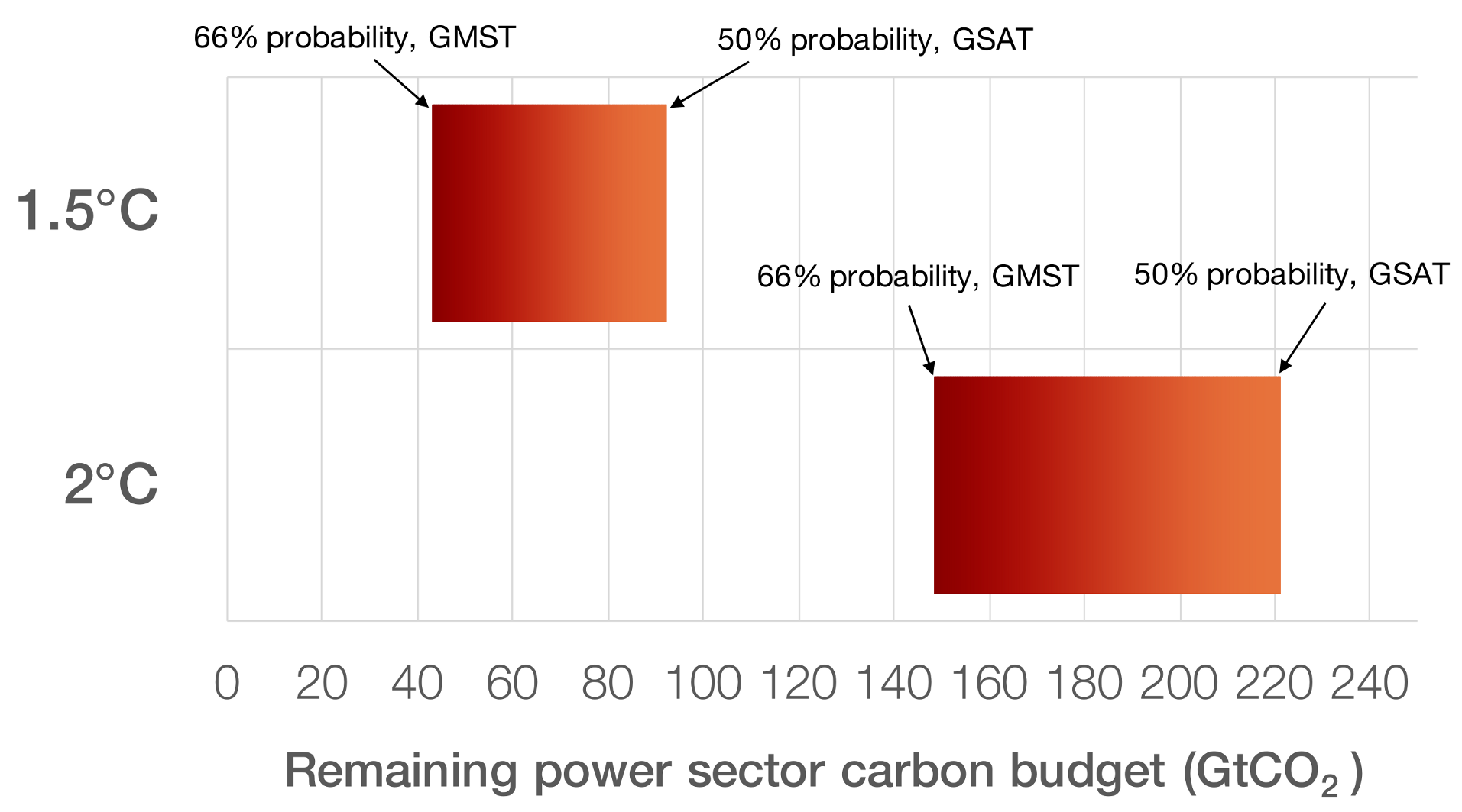
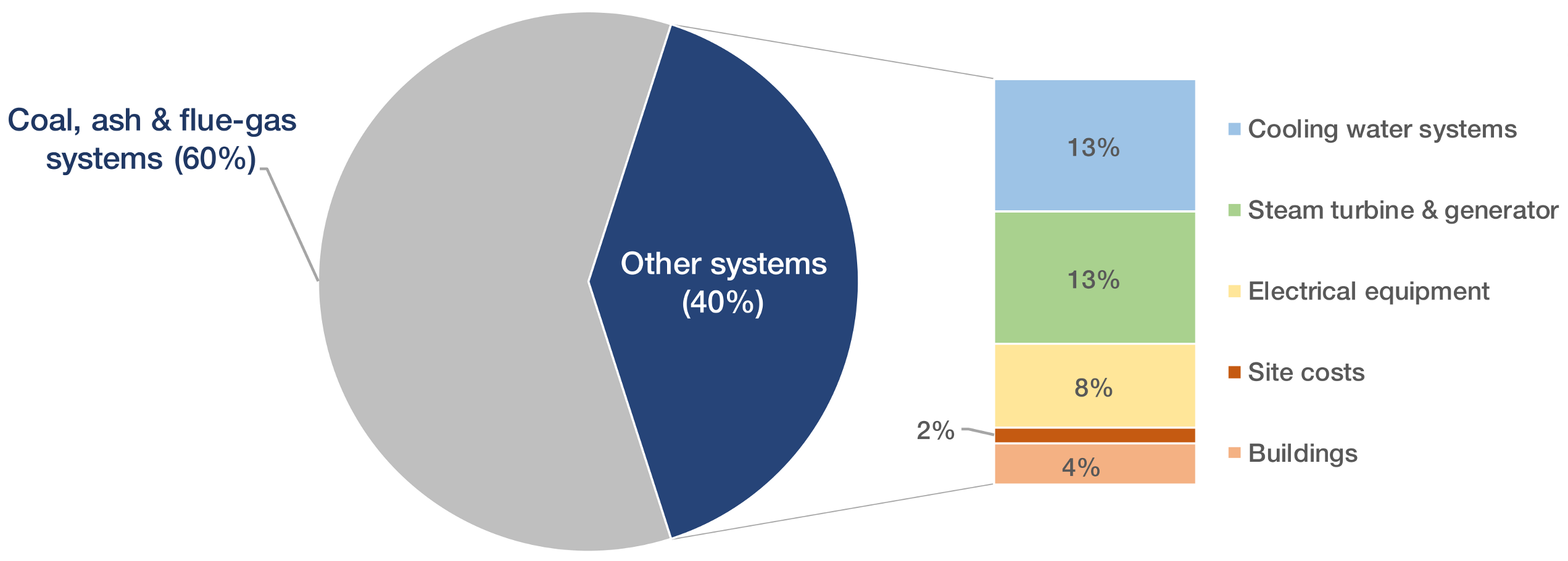
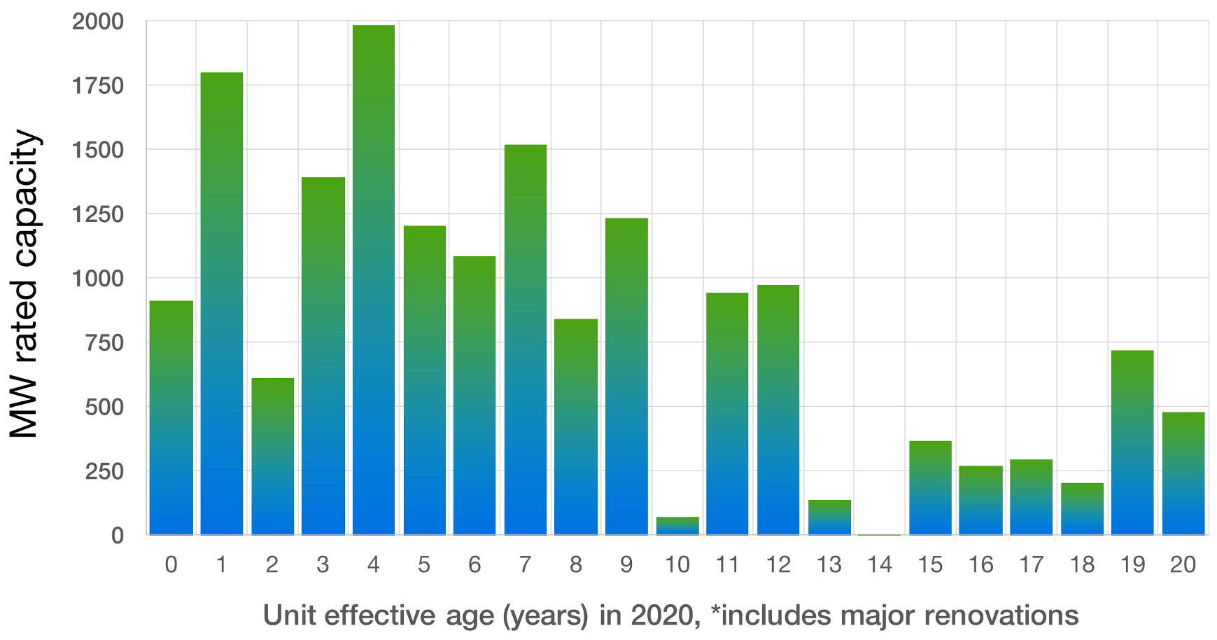
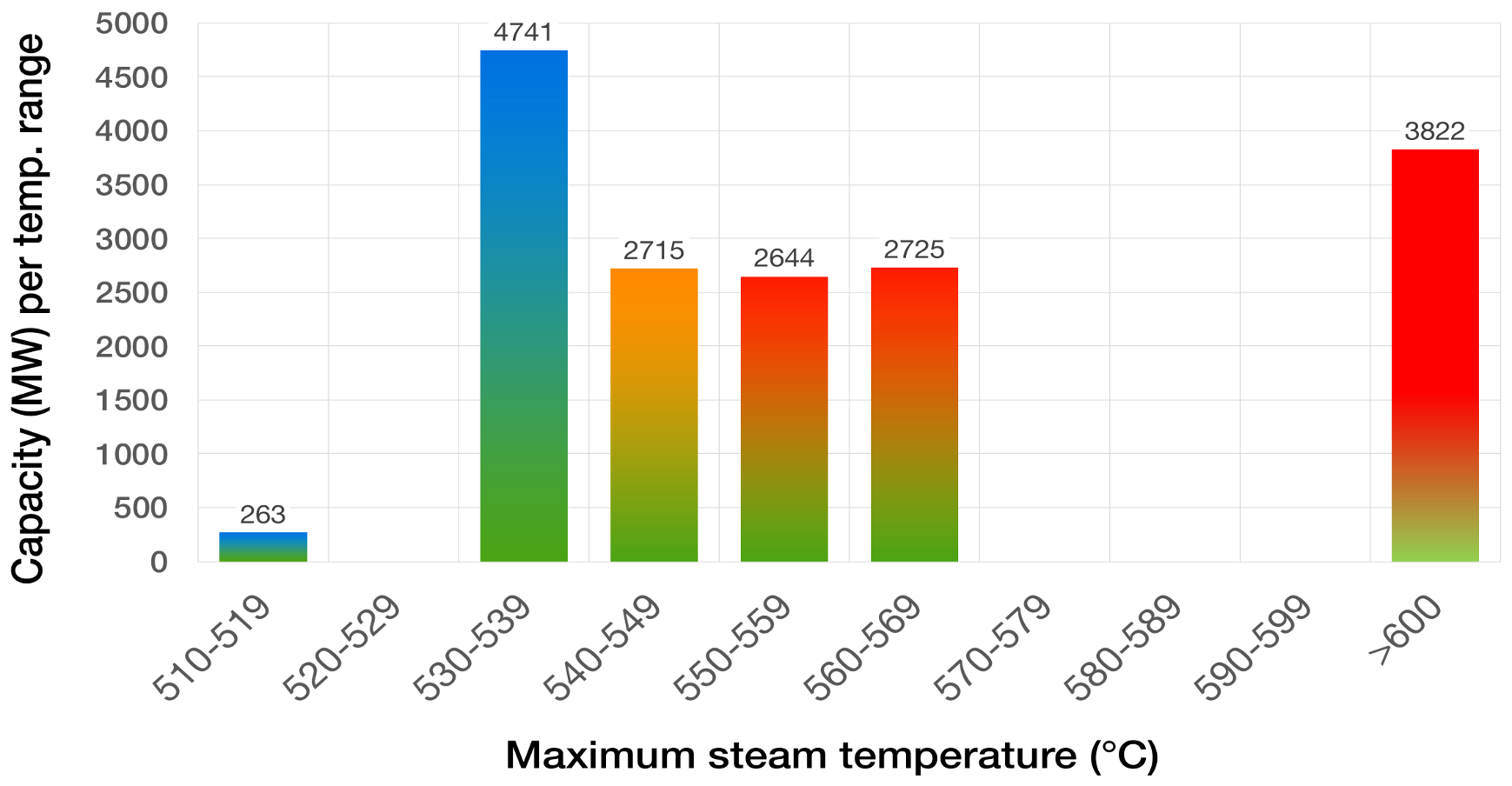
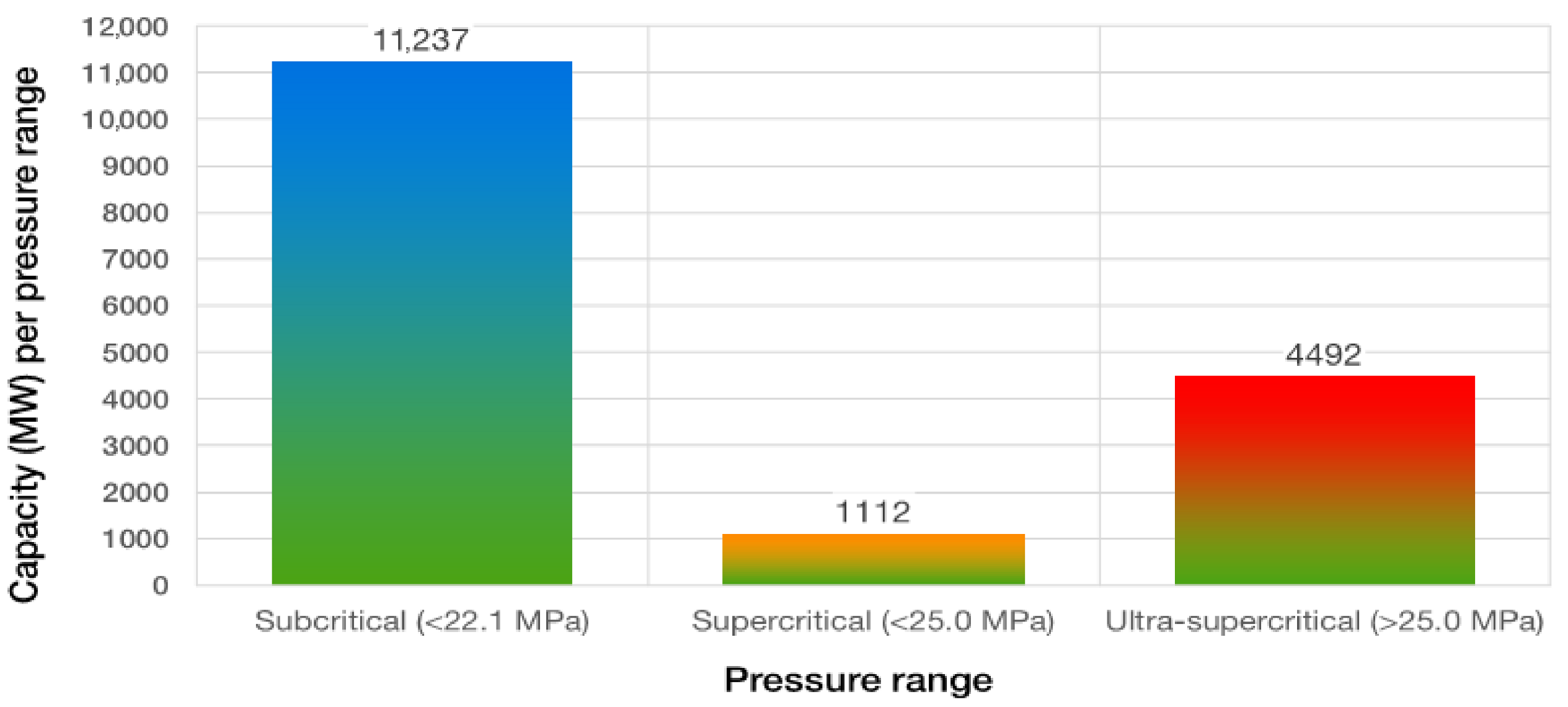
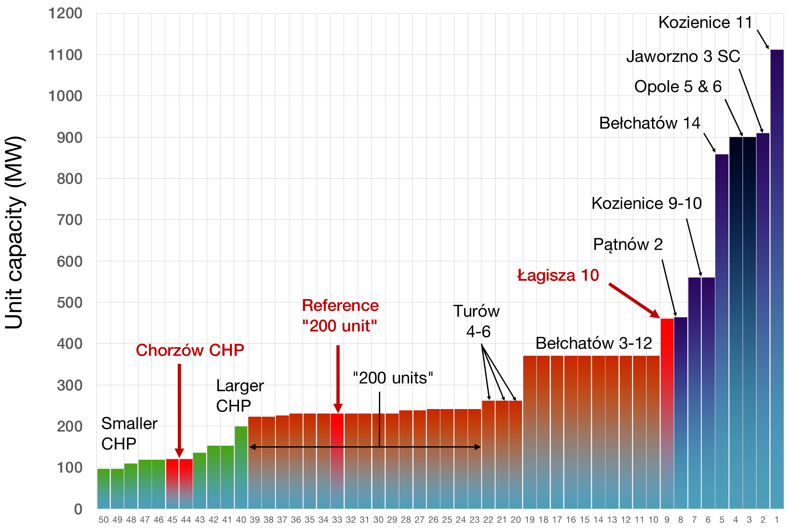
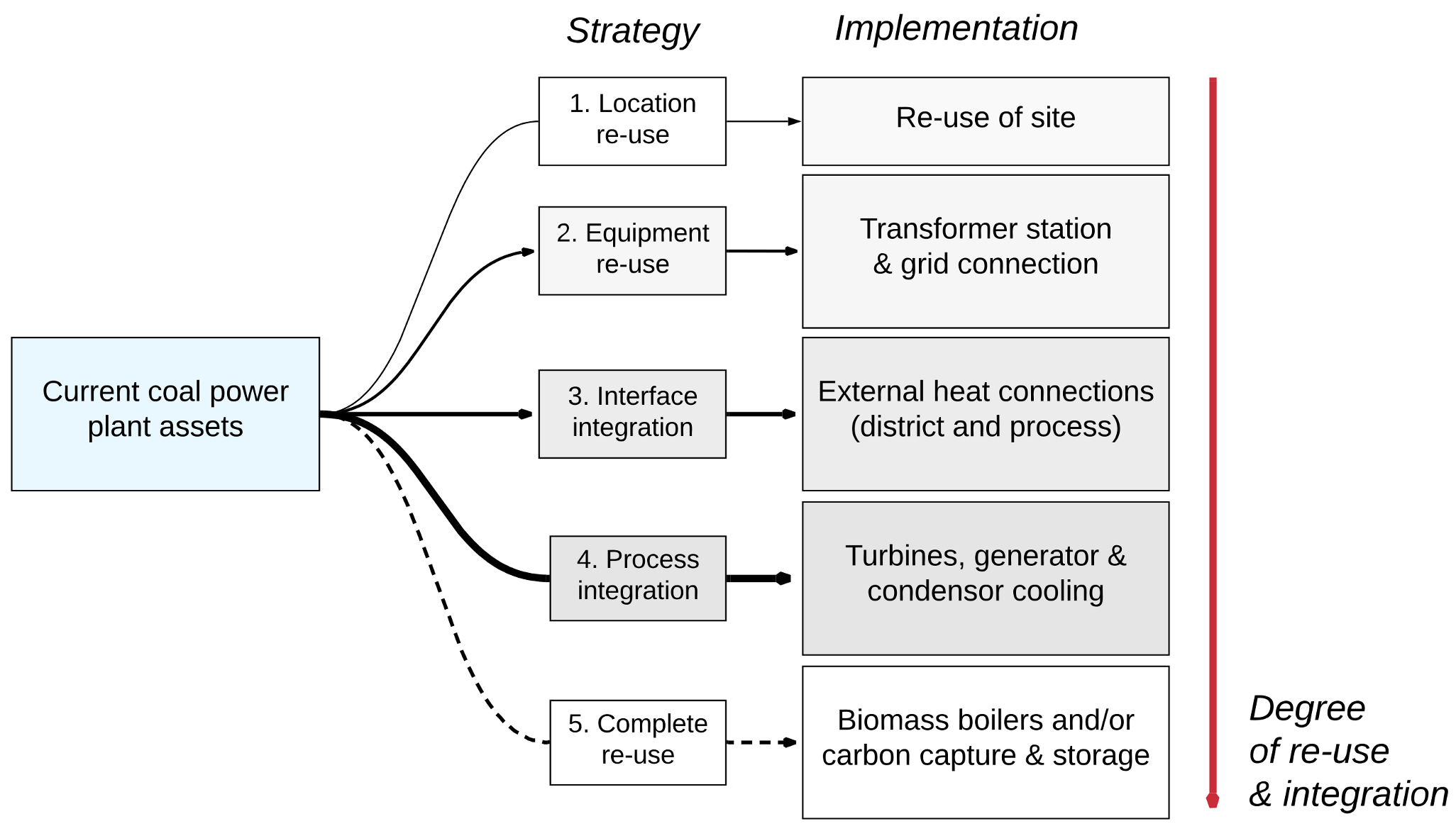
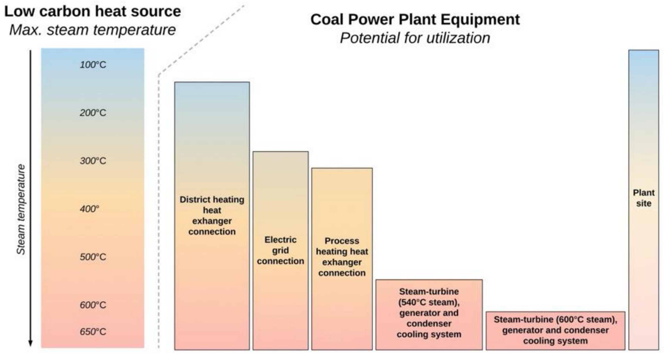
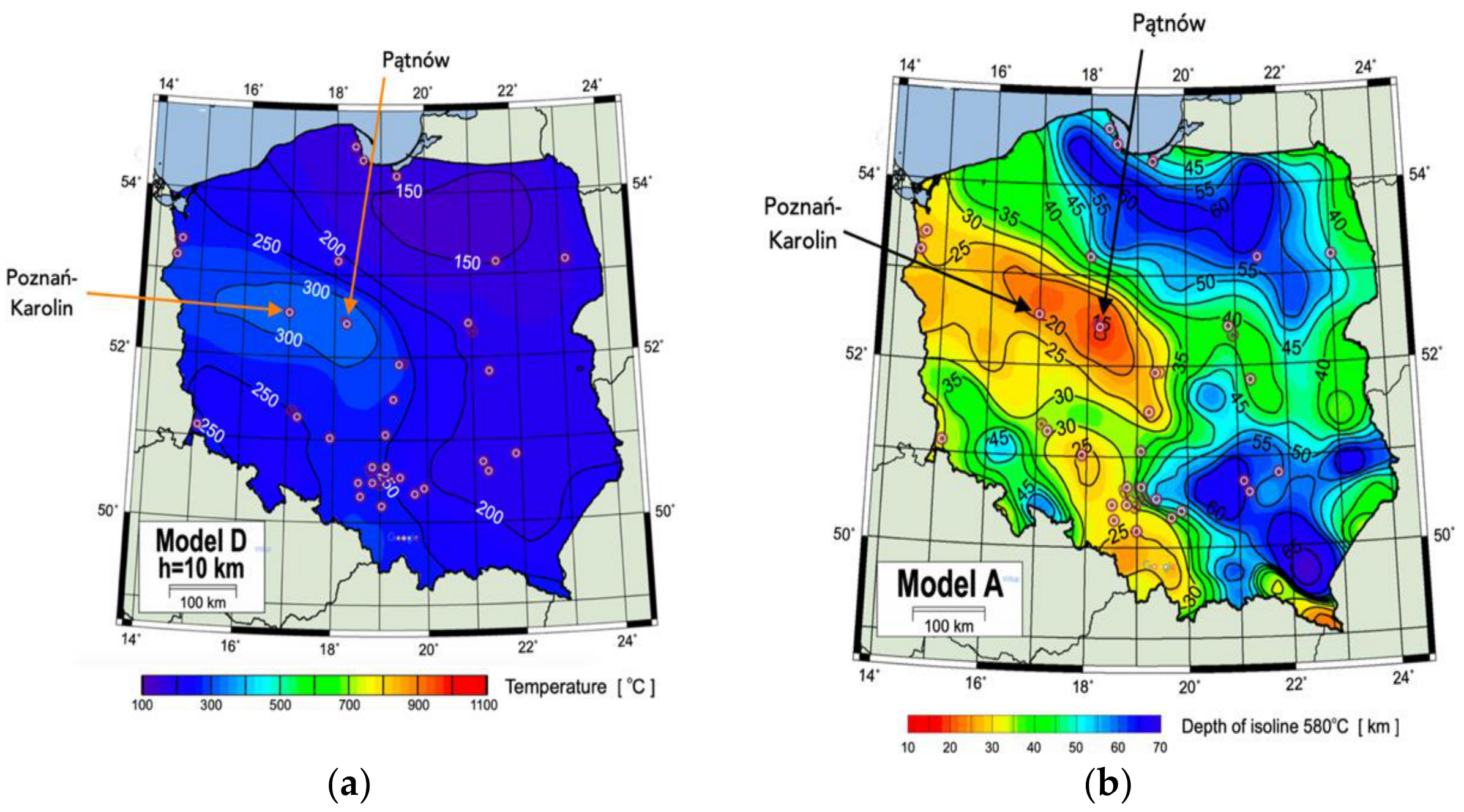
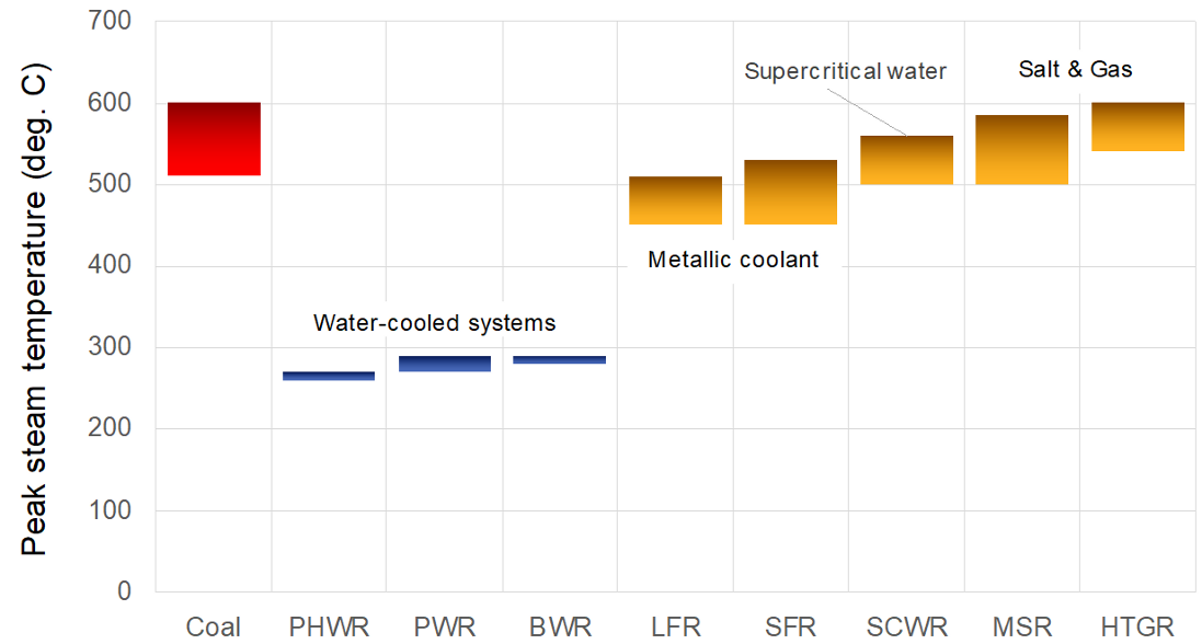
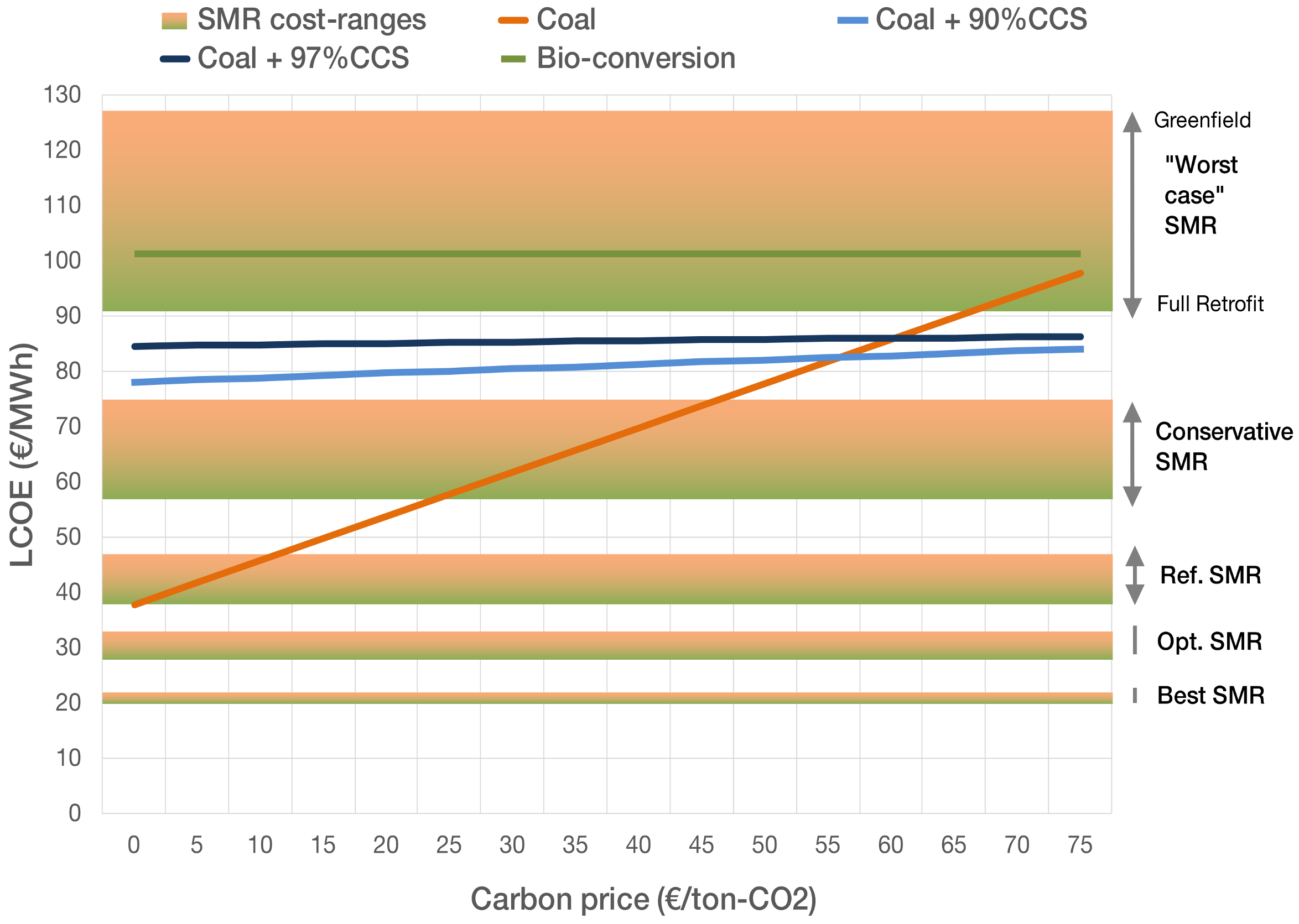
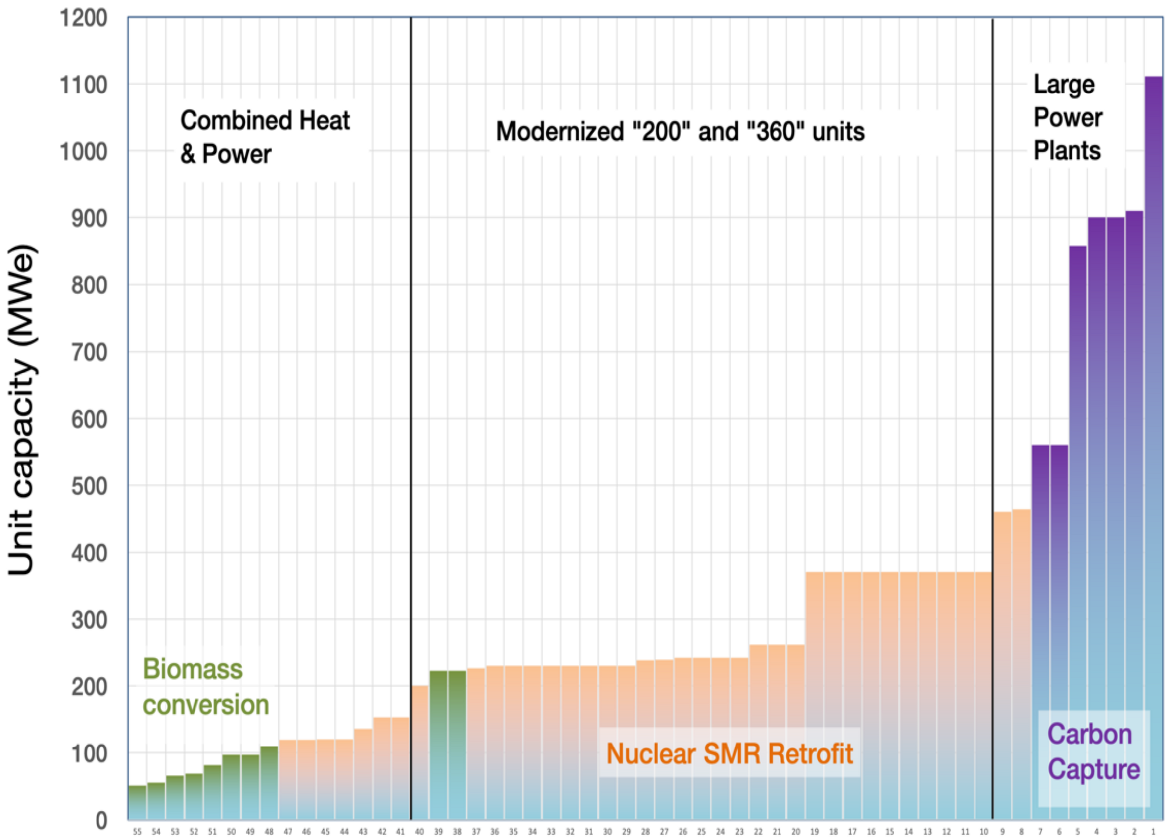
Table 1.
Direct land use of low-carbon options compared to coal power.
| Generation Type | Annual Output Replacement Possible within Site Boundary | Applicable for Retrofit Decarbonization Analysis | Assessed in this Study |
|---|---|---|---|
| Coal | 100% (reference value) | N/A | N/A |
| Coal + CCS | 80–100% | Yes | In Supplementary Materials Section 2 |
| Biomass | >50% | Yes | In Supplementary Materials Section 3 |
| NGCC + CCS | >100% | Yes | No |
| Nuclear | >100% | Yes | Yes |
| Wind (onshore) | Up to 0.6% | No | No |
| Solar PV | Up to 1.6% | No | No |
| Wind + Solar PV | Up to 1.8% | No | No |
| Solar CSP | Up to 1.7% | No | No |
| Geothermal | Up to 90% | Yes | Yes |
Table 2.
Threshold requirements for coal unit inclusion in retrofit decarbonization analysis.
| Parameter | Value | Motivation |
|---|---|---|
| Maximum current effective age of relevant equipment | 20 years | One of the main motivations for retrofit decarbonization is to make use of the remaining useful life of what would otherwise be stranded assets. Much of the equipment at units that have not undergone modernizations in the last 20 years (and thus have an “effective age” higher than this) are significantly depreciated, and such units are likely in need of substantial investments in the near-term to carry on operating. These units are much more likely to be decommissioned than to be remain viable candidates for re-use of equipment in the next 10–15 years, and they are therefore excluded from this analysis. |
| Minimum rated capacity | 50 MWe | A total of less than 400 MWe of capacity resides in coal units meeting the effective age criterion with an individual power rating lower than 50 MWe. These are mainly very small CHP units on small plot sites close to town centers, which would be very challenging sites for any retrofit project. |
Table 3.
Categorization of Polish Coal Power Units.
| Category | Description | Technical Details |
|---|---|---|
| 1. Combined heat and power plants [Green in Figure 6] | Units with an individual electric capacity of less than 200 MWe, providing electricity and district/process heating | Capacity: 1546 MWe Number of units: 15 Subcritical steam cycles Temperature: 510–550 °C Located in, or adjacent to, cities Small site footprints |
| 2. “200” and “360” units [Brown in Figure 6] | The “200-units” (essentially identical units in the range of ~200 MWe) constitute the bulk of the polish power system, built in the 1970s. Out of 12.3 GWe total installed capacity, 4.9 GWe have been modernized. “200-units” potentially applicable for retrofit decarbonization analysis are available at Kozienice, Patnów, Połaniec, Turów, Ostrołęka, and Jaworzno power plants. In addition, the Bełchatów plant has 11 units in the 380–394 MW range (“360”-units), 10 of which have been modernized between 2008 and 2016, for a combined applicable capacity of 3874 MWe in this category. At the Opole plant, units 1–4 (1532 MWe) are 360-units that have not been included here, but they are not unlikely to be further modernized in the near future and therefore are potentially applicable. | Capacity: 8824 MWe # of units: 31 Subcritical steam cycles Temperature: 535–560 °C Many units together at very large power plants Typically located in rural areas with larger site footprints Turów and Bełchatów are located at the large lignite mines that feed them |
| 3. Large units [Purple in Figure 6] | Large units are defined as having a capacity larger than 400 MWe. In total, 10 included units, nine of which were in operation at the end of 2019, are included. In addition, the 496 MW Turow-11 unit is expected to enter commercial operation before the end of 2020. | Capacity: 6723 MWe # of units: 10 Mainly supercritical steam cycles Temperature: >560 °C All units are add-ons at existing plants |
Table 4.
Modern or modernized coal units at the Pątnów site.
| Unit Name | Electric Capacity | Year of Commissioning or Modernization | Live Steam Parameters |
|---|---|---|---|
| Pątnów-1, B1 | 222 MWe | 2016 | 535 °C, 12.75 MPa |
| Pątnów-1, B2 | 222 MWe | ||
| Pątnów-2 | 540 MWe | 2008 | 540 °C, 25.8 MPa |
Table 5.
Water-cooled reactor classes and operating steam parameters.
| Type of Reactor | Reactor Coolant Pressure/Temperature | Supplied Steam Pressure/Temperature |
|---|---|---|
| Pressurized Water Reactor (PWR) | 12.7–15.5 MPa/300–330 °C | 5.7–7 MPa/270–290 °C |
| Pressurized heavy-water reactor (PHWR) | 8.7–10.0 MPa/310–320 °C | 4.0–5.1 MPa/250–260 °C |
| Boiling Water Reactor (BWR) and water-cooled, graphite moderated reactor (RBMK) | 6.9–7.5 MPa/290 °C | |
Table 6.
Non-water-cooled reactor classes and operating steam parameters.
| Type of Reactor | Supplied Steam Temperature | Development Status |
|---|---|---|
| Sodium fast reactor (SFR) | 450–530 °C | Operating |
| Lead fast reactor (LFR) | 450–530 °C | Demonstrated and Under Construction |
| High-temperature gas-cooled reactor (HTGR) | 540–600 °C | Operating |
| Molten salt reactor (MSR) | 535–585 °C | Prototype |
| Super-critical water reactor (SCWR) | 500–560 °C | Concept |
Table 7.
Examples of applicable gas and salt cooled nuclear reactors under development.
| Name | Coolant | Thermal Power Per Unit | Steam Temperature | Expected First Operation |
|---|---|---|---|---|
| HTR-PM (China) | Gas | 250 MWth | 570 °C, current 600 °C, 2nd-gen | 2021 |
| Kairos KP-FHR (US) | Salt | 320 MWth | 585 °C | 2030 or earlier |
| Terrestrial iMSR (Canada) | Salt | 400 MWth | ~585 °C (600°C coolant) | Late 2020s |
| ThorCon (US) | Salt | 557 MWth | 547 °C | Late 2020s or early 2030s |
| X-Energy (US) | Gas | 200 MWth | 565 °C | 2027 |
| Seaborg (Denmark) | Salt | 250 MWth | 570–580 °C | ~2027 |
| USNC (US/Canada) | Gas | 15 MWth | ~550 °C | Mid 2020s |
| U-Battery | Gas | 10 MWth | >600 °C | 2028 |
| Moltex SSR-W/U/Th | Salt | ~330 MWth | N/A | Early 2030s |
| Terrapower MCFR | Salt | 600–2500 MWth | N/A | Demo: 2027 Commercial: Early 2030s |
| SINAP TMSR-LF (China) | Salt | 2–373 MWth | Up to 600 °C (700 °C coolant) | 2 MWth: 2021/22 373 MWth: 2030 |
| Flibe Energy LFTR (US) | Salt | 600 MWth | N/A | N/A |
| Elysium (US) | Salt | 125 MWth (and other sizes) | N/A | 2030 |
Table 8.
Technical Site Requirements Comparison, Coal and Nuclear.
| Parameter | Coal Power Plant | Nuclear Power Plant |
|---|---|---|
| Fuel delivery | Up to several million tons per year | Low volume and infrequent |
| Cooling water a (a) Direct cooled (b) Tower cooled | (a) 3 m3/s per 100 MWe (b) 0.2 m3/s abstracted, about 0.05 m3/s evaporated per 100 MWe b | |
| Geology | Ground able to support heavy loads | Seismically stable ground able to support heavy loads with virtually no differential settlement |
| Access (a) Construction materials (b) Abnormal loads | (a) Road, rail, or sea access to deliver up to >1 million tons (b) Road or sea access to deliver about 80 very large loads | |
| Waste disposal | Means of disposing of up to 60,000 tons per year of ash per 100 MWe | Near to railhead or port for transport of irradiated fuel |
| Special considerations | Delivery of about 20,000 tons per year of limestone and disposal of about 30,000 tons per year per year of gypsum per 100 MWe | Subject to nuclear regulatory approval and local social acceptance for siting |
| Grid integration | Suitable for connection to a point on the grid able to accept output of station | |
a: Details depend on the type of coal plant (subcritical, super-critical, ultra-super-critical) and type of nuclear plant. Figures roughly correspond to a super-critical coal plant and a high-temperature nuclear plant operating on an identical steam cycle. For a typical light-water reactor steam cycle, cooling water needs are higher. b: The use of cooling towers requires that a suitable make-up water supply be identified, which would typically amount to 2% to 3% of the total cooling water flow.
Table 9.
Assumed overnight capital cost breakdown of an advanced high-temperature SMR.
| Component | Budget Share | Possible Retrofit Savings | Description |
|---|---|---|---|
| Pre-construction costs | 5% | 0% | Costs associated with development |
| Non-EPC indirect costs | 5% | ||
| Owner’s costs | 1% | ||
| Supplementary costs | 1% | ||
| Contingency | 5% | ||
| Fuel Core Load | 3% | ||
| Infrastructure, incl: | 80% | 35–44% | Depending on integration scheme |
| Reactor | 11% | 0% | Not available at coal plant |
| Primary heat transfer system | 11% | 0% | Not available at coal plant |
| Intermediate heat transfer system | 10% | 0% | Not available at coal plant |
| Steam cycle | 25% | 80–97% | Depending on required changes in the existing steam cycle |
| Reactor Aux Systems | 2% | 0% | Not available at coal plant |
| Instrumental and control | 6% | 25–35% | Control room rebuild and advanced control for the SMR |
| Plant auxiliaries | 6% | 25–35% | e.g., spent fuel handling, additional cooling pumps |
| Electrical | 4% | 50–70% | e.g., additional electrical equipment, back-up generators |
| Civil structures | 25% | 40–50% | e.g., nuclear buildings and control room needed, security perimeter |
| Capex fraction | ∑100% | 28–35% | Exact value depends on the integration scheme |
Table 10.
LCOE reductions attainable by coal retrofit of advanced SMRs.
| Case Description | WACC (%) | Build Time (Years) | Greenfield CAPEX (€/kWe) | Greenfield LCOE (€/MWh) | Retrofit LCOE (€/MWh) | Retrofit LCOE Savings |
|---|---|---|---|---|---|---|
| Worst case | 10% | 6 | 7000 | 127 | 91 | 28% |
| Conservative | 7% | 5 | 6000 | 75 | 57 | 24% |
| Reference | 6% | 4 | 4000 | 47 | 38 | 19% |
| Optimistic | 5% | 3 | 3000 | 33 | 28 | 15% |
| Best case | 3% | 2 | 2000 | 22 | 20 | 9% |
Table 11.
SWOT-analysis of retrofit decarbonization options.
| Positive Factors | Negative Factors | ||
|---|---|---|---|
| Internal | Strengths | Weaknesses | |
| Geothermal |
|
| |
| Nuclear |
|
| |
| Biomass |
|
| |
| Coal + CCS |
|
| |
| External | Opportunities | Threats | |
| Geothermal |
|
| |
| Nuclear |
|
| |
| Biomass |
|
| |
| Coal + CCS |
|
|
Table 12.
Comparison of options for retrofit decarbonization of coal power plants and their scope of potential implementation in Poland.
Table 12.
Comparison of options for retrofit decarbonization of coal power plants and their scope of potential implementation in Poland.
| Parameter | Geothermal | Nuclear SMR | Biomass | CCS |
|---|---|---|---|---|
| Technological availability | 2030s for EGS deep-drill | Early 2030s | Available | Available |
| Energy security impacts |  (no fuel) |  |  (domestic fuel) |  (domestic fuel) |
| Domestic input in project value |  |  |  |  |
| Re-utilization potential of existing infrastructure value |  |  |  |  |
| Social acceptance |  |  |  |  |
| Tie-in with Polish energy policy |  |  |  |  |
| Implementation potential for units 50–200 MWe (MW) | N/A | 1120 | 626 | 0 |
| Implementation potential for units 200–500 MWe (MW) | N/A | 8920 | 444 | 0 |
| Implementation potential for units >500 MWe (MW) | 0 | 0 | 0 | 5800 |
| Total implementation potential MW | N/A | 10,040 | 1070 | 5800 |
| Total implementation potential TWh/year | N/A | 79 | 7 | 33 |
Publisher’s Note: MDPI stays neutral with regard to jurisdictional claims in published maps and institutional affiliations. |
© 2020 by the authors. Licensee MDPI, Basel, Switzerland. This article is an open access article distributed under the terms and conditions of the Creative Commons Attribution (CC BY) license (http://creativecommons.org/licenses/by/4.0/).
Share and Cite
MDPI and ACS Style
Qvist, S.; Gładysz, P.; Bartela, Ł.; Sowiżdżał, A. Retrofit Decarbonization of Coal Power Plants—A Case Study for Poland. Energies 2021, 14, 120. https://0-doi-org.brum.beds.ac.uk/10.3390/en14010120
AMA Style
Qvist S, Gładysz P, Bartela Ł, Sowiżdżał A. Retrofit Decarbonization of Coal Power Plants—A Case Study for Poland. Energies. 2021; 14(1):120. https://0-doi-org.brum.beds.ac.uk/10.3390/en14010120
Chicago/Turabian StyleQvist, Staffan, Paweł Gładysz, Łukasz Bartela, and Anna Sowiżdżał. 2021. "Retrofit Decarbonization of Coal Power Plants—A Case Study for Poland" Energies 14, no. 1: 120. https://0-doi-org.brum.beds.ac.uk/10.3390/en14010120
Note that from the first issue of 2016, this journal uses article numbers instead of page numbers. See further details here.