Article

Unified Power Converter Based on a Dual-Stator Permanent Magnet Synchronous Machine for Motor Drive and Battery Charging of Electric Vehicles

School of Engineering, Campus of Azurém, University of Minho, 4800-058 Guimarães, Portugal
*
Author to whom correspondence should be addressed.
Submission received: 6 May 2021 / Revised: 27 May 2021 / Accepted: 2 June 2021 / Published: 7 June 2021

Abstract

:
An electric vehicle (EV) usually has two main power converters, namely one for the motor drive system and another for the battery-charging system. Considering the similarities between both converters, a new unified power converter for motor drive and battery charging of EVs is propounded in this paper. By using a single unified power converter, the cost, volume, and weight of the power electronics are reduced, thus also making possible a reduction in the final price of the EV. Moreover, the proposed unified power converter has the capability of bidirectional power flow. During operation in traction mode, the unified power converter controls motor driving and regenerative braking. Additionally, during operation in battery-charging mode, with the EV plugged into the electrical power grid, the unified power converter controls the power flow for slow or fast battery charging (grid-to-vehicle (G2V) mode), or for discharging of the batteries (vehicle-to-grid (V2G) mode). Specifically, this paper presents computer simulations and experimental validations for operation in both motor-driving and slow battery-charging mode (in G2V and V2G modes). It is demonstrated that the field-oriented control used in the traction system presents good performance for different values of mechanical load and that the battery-charging system operates with high levels of power quality, both in G2V and in V2G mode.

1. Introduction

Electric vehicles (EVs) are increasingly a reality of our days; however, the widespread introduction of EVs in the market has been constrained by several technical issues, limiting their performance and increasing their cost. Thus, the introduction of EVs brings new opportunities, namely their integration into the power grid as a stabilizing element, and also contributes to improving energy efficiency and cost reduction [1,2,3].
The power electronics associated with the powertrain systems for EVs have increased complexity, which raises technical and economic issues more relevant than those related with the electric machine. In this way, the controller of the electric machine has vital importance, being an essential part in terms of performance and overall powertrain efficiency. Conversely, the use of bidirectional power converters for battery charging allows to store the energy produced during low-consumption hours, for later return to the power grid during peak-consumption hours [4]. This feature can allow better power management whenever needed, in accordance with both the power grid and the EV user. These bidirectional systems can appear as an asset for the power grid. Taking into consideration the existing opportunities, not only in the development of powertrain systems, but also in battery-charging systems, there is a significant investment in the development of solutions for electric mobility [5,6].
An EV has a power converter that drives the electric machine accountable for the motor drive. Additionally, there is a second power converter used to charge (or discharge) the batteries. Similarities can be observed between these two power converters, which allows foreseeing a convergence between them in a single unified power converter. When the EV is circulating, the power converter operates bidirectionally for traction and regenerative braking. Similarly, when the EV is immobilized and plugged into the power grid, the power converter can also operate bidirectionally, having the function of controlling the power flow among the power grid and the batteries, in charging or discharging mode. Therefore, an opportunity was identified for the creation of a new topology of power converters that integrates the powertrain system and the battery-charging system.
The US Department of Energy and NASA proposed the first unified power converter [7], and in 1992, Rippel and Cocconi patented the first unified power converter [8]. Since then, several topologies have been studied and proposed [9,10,11]. Diversity is wide, with split-phase electric machines [12,13,14], with multiphase electric machines [15,16,17], with voltage-source power converters [2,18], with current-source power converters [19], and with [20,21] or without [22,23] galvanic isolation. In this paper, the presented unified topologies only focus on slow battery-charging mode.
In 1994, AC Propulsion Inc. patented the unified power converter topology shown in Figure 1 [24], being used in the BWM Mini E [25]. This topology uses a single-phase contactor and a contact to reconfigure the electric machine windings. In battery-charging mode, the EV is plugged into the power grid with a single-phase connection. Two windings of the electric machine are used as coupling inductors with the power grid. A single-phase contactor exists in the system to prevent a short circuit when the contact is accidentally closed [2]. To guarantee the operation with a unitary power factor, the dc-link voltage must be superior than the peak value of the power grid voltage. This restriction can be overcome by adding a dc–dc power converter between the dc-link and the batteries [2,26]. Moreover, this topology allows for bidirectional power flow.
Figure 2 presents the topology proposed by Surada et al. [27]. This topology can be used in any type of three-phase electric machine for the powertrain system. This topology can work in five modes of operation: (1) boost power converter, adjusting the battery voltage to the dc-link voltage; (2) buck power converter, charging the batteries during regenerative braking; (3) plug-in system, charging the batteries from the power grid; (4) single-phase power converter, powering loads from the EV batteries in the case of a power grid failure; and (5) connection to the power grid, injecting power from the EV traction batteries to the power grid.
The topology presented in Figure 3 uses the neutral point of the electric machine to perform a connection with the power grid. The first stage of the battery-charging system has an uncontrolled rectifier bridge, so the power flow is unidirectional. Hence, this topology does not allow the return of power to the power grid. The positive output terminal of the rectifier bridge is linked to the neutral point of the electric machine, and the negative output terminal is linked to the negative terminal of the batteries. The current in the electric machine windings is continuous; therefore, any braking system to brake the electric machine rotor is not necessary, because there is no torque produced [28].
Hegazy et al. presented in [23] a single-phase bidirectional topology, which can be seen in Figure 4. The battery-charging and powertrain systems comprise a power converter with eight fully controlled power semiconductors. Six semiconductors are used like in a classic three-phase power converter topology, while the other two are introduced in series with the semiconductors of two legs of the power converter. This power converter presents four operation modes: (1) battery charging from a single-phase power grid; (2) single-phase inverter, where part of the stored energy in the EV battery is returned back to the power grid; (3) motor drive, transferring power from the dc link to the induction machine; and (4) regenerative braking, transferring power from the electric machine to the dc link [23].
In Figure 5 is shown the integrated system proposed by Haghbin et al. [14]. This system uses a split-phase interior permanent magnet synchronous machine (PMSM) and two power converters. The stator of the electric machine has six windings, where three windings are equally shifted from the others, more specifically 120 electrical degrees. The power of the electric machine is divided between two converters. Therefore, each one can provide half of the electric machine power. It is supposed that the neutral points of the two three-phase windings are not connected between them. In addition, if one power converter fails, the electric machine can operate with half the power. When the three-phase windings are connected in star topology, the neutral points are used to connect with the power grid. In battery-charging mode, it is not necessary to brake the rotor, because the electric machine does not produce any torque. The charging system is non-isolated and bidirectional, but it does not allow fast charging [14].
Figure 6 presents a unified topology based on a switched-reluctance machine (SRM) [9], where the power converter acts as an interleaved boost converter. Similar to the aforementioned topologies, the electric machine windings are used as coupling filters with the power grid [9,29].
In traction mode, contactor KM1 stays in state 1 (up) and contactor KM2 is closed. The bottom semiconductors (S2, S4, S6, S8) are controlled, while the top semiconductors are kept in freewheeling operation. In the demagnetization stage of the windings, the stored energy is oriented to the batteries through the freewheeling diodes. The regenerative braking is controlled by shifting the commutation backward, where the electric machine acts as a generator [9]. In battery-charging mode, contactor KM1 is in state 2 (down) and contactor KM2 is open. With this configuration, the power converter works as a buck-boost dc–dc converter with power factor correction. The controlled semiconductor S5 stays turned on, while the controlled semiconductor S6 is switched. The diode De is added to prevent a short circuit when the controlled semiconductor S6 is active. The windings A and B are used as coupling filters with the power grid, and winding C is used as an energy storage element of the buck-boost dc–dc power converter [9].
This paper is summarized as follows. Section 2 describes the proposed unified power converter topology, and the applied control algorithms are presented in Section 3. Section 4 presents the simulation results, while Section 5 shows the experimental validation. Finally, Section 6 provides conclusions about the proposed solution.

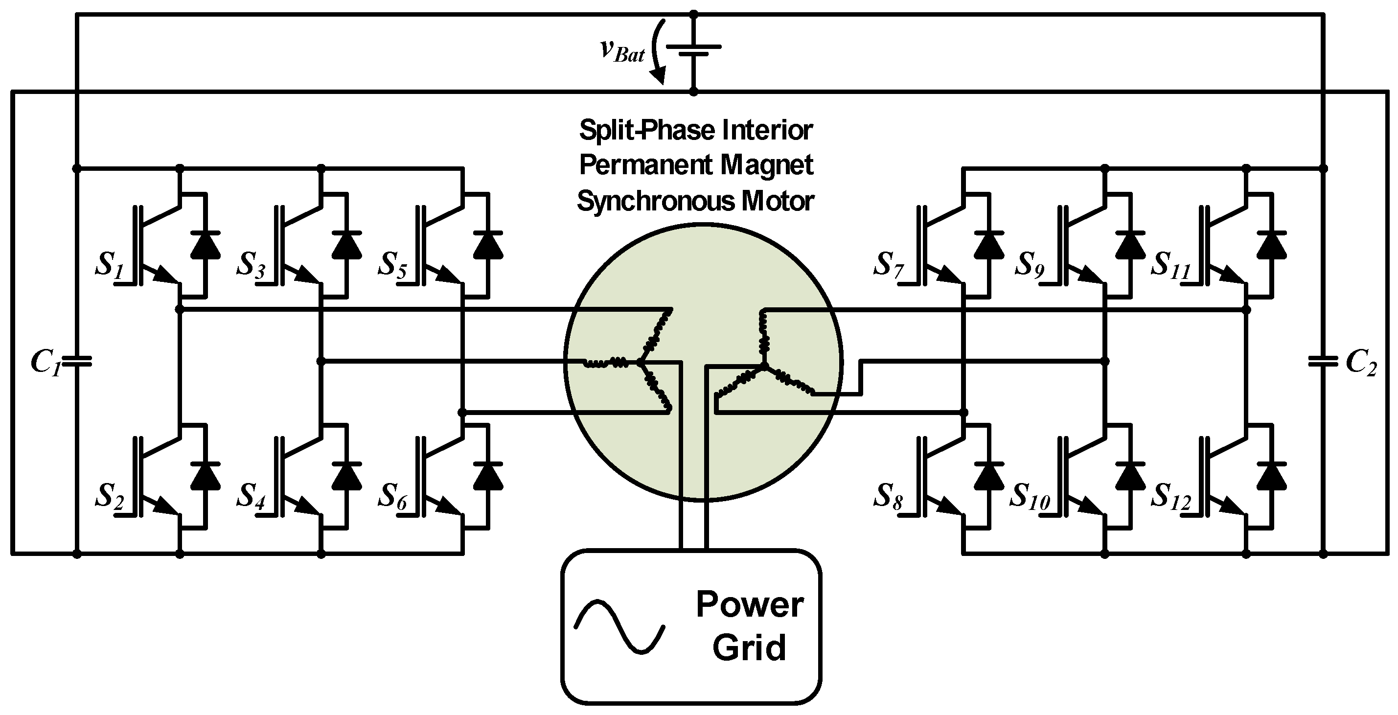
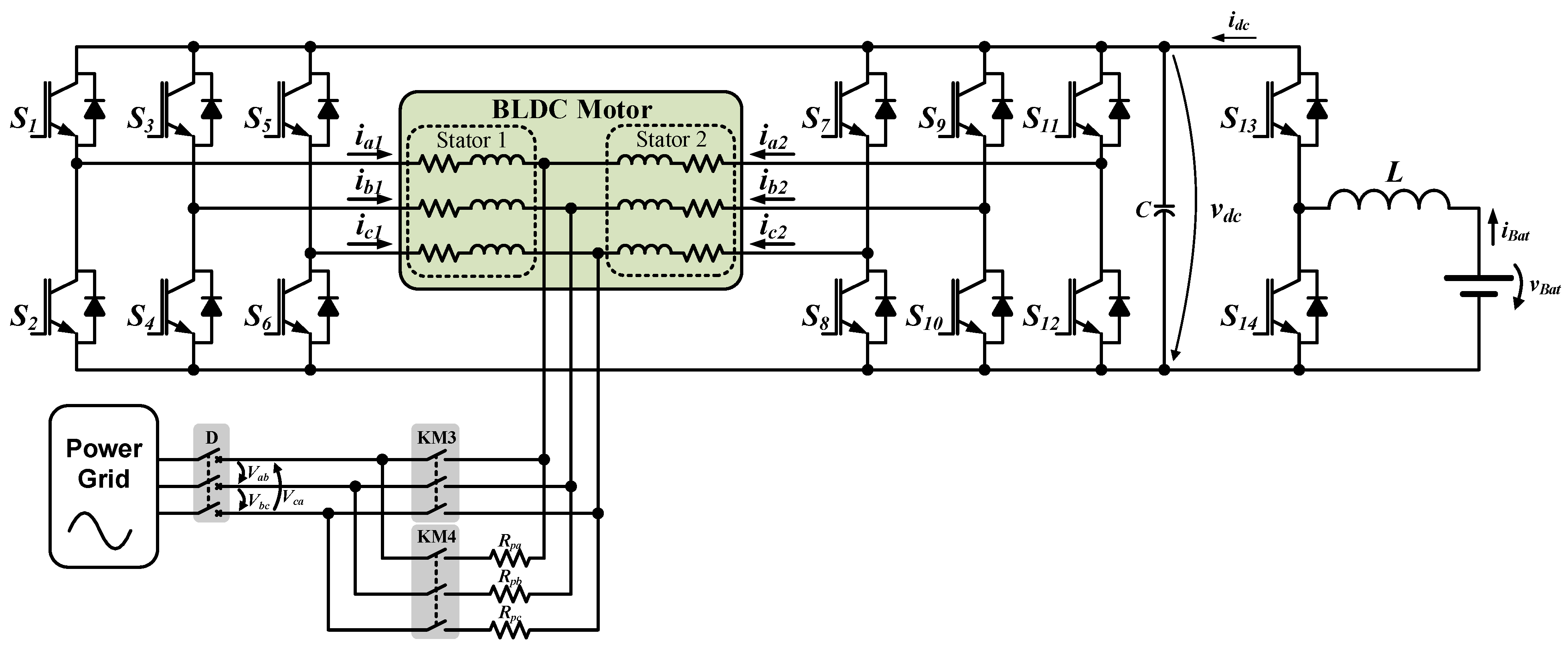
2. Proposed Unified Power Converter

Figure 7 presents the proposed unified power converter topology, which comprises an electric machine, two three-phase ac–dc converters, a pre-charge circuit (comprising resistors and contactors), and a buck-boost dc–dc converter.
The proposed topology is bidirectional and non-isolated, integrating the powertrain and battery-charging systems. The electric machine is powered by two three-phase power converters, with the system being more reliable when compared with solutions with a single power converter, since the total power is divided between the two converters. Depending on the type of failure, the electric machine can operate with half the power, which is an important characteristic of the proposed unified power converter.
In battery-charging mode, the control algorithm for this topology needs to guarantee that the current in each winding is balanced. In this way, the current on each side of the windings cancels the effect of the opposite side current. This ensures that the rotating magnetic field components developed on the stator cancel themselves. Therefore, the resultant magnetic force will be zero and the EV is kept immobilized.
In traction mode, the dc–dc power converter works as a boost converter to control the dc-link voltage and supplying power to the electric machine. In regenerative braking mode, this converter works as a buck converter. The dc-link voltage, during the charging of the batteries, is controlled by the three-phase power converters.
The proposed power converter can be used for slow or fast battery-charging operations. In both cases, the power factor is near the unit and the power grid currents are sinusoidal. The EV batteries can be charged from the power grid (grid-to-vehicle (G2V) mode), or they can deliver part of the stored energy back to the power grid (vehicle-to-grid (V2G) mode). In G2V mode, the dc–dc converter behaves as a buck converter and the ac–dc converter works as an active rectifier. In contrast, in V2G mode, the ac–dc converter operates as an inverter and the dc–dc converter as a boost converter.
Figure 7 also shows the connection with the three-phase power grid that is used to carry out fast battery charging. However, the paper focuses on the slow battery-charging operation. In this sense, it uses a single-phase connection with the power grid.
Table 1 shows a comparison that highlights the main characteristics of the unified power converters referred to in Section 1, as well as the unified power converter proposed in this paper. These unified power converters are compared according to the need of a special machine (access to winding terminals), the type of power grid connection, the necessity of hardware reconfiguration, the requirement of external inductors, and the capability of bidirectional operation (V2G mode).

3. Control Algorithms for the Unified Power Converter

This section presents the control algorithms for the proposed unified power converter. The presented control algorithms for battery-charging mode only refer to slow battery charging, being in V2G and G2V modes. V2G mode allows devolving some part of the energy stored in the batteries to the power grid, while G2V mode is used when the EV needs to be charged. The dc–dc power converter is not presented in this work.

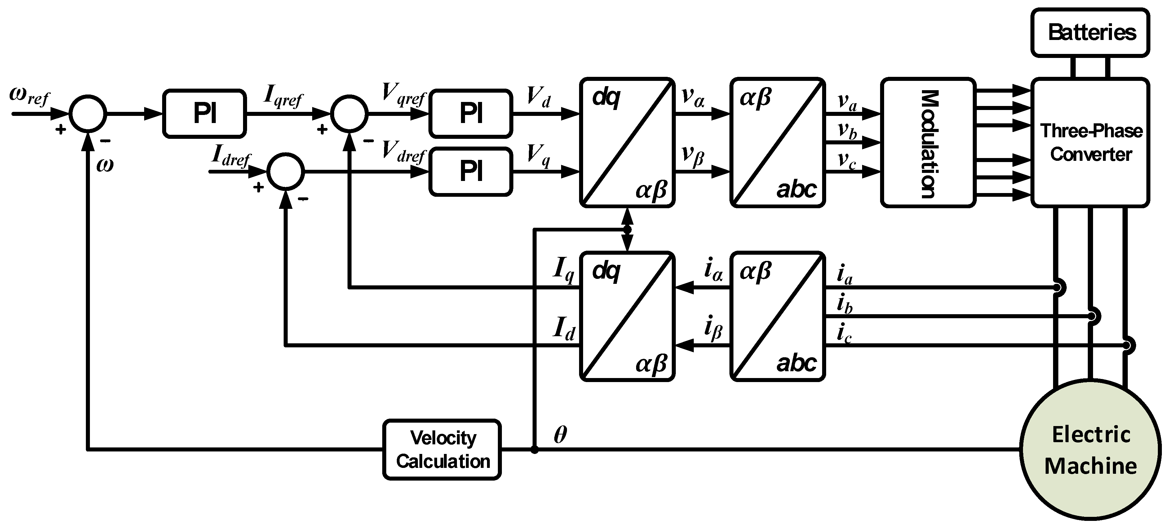
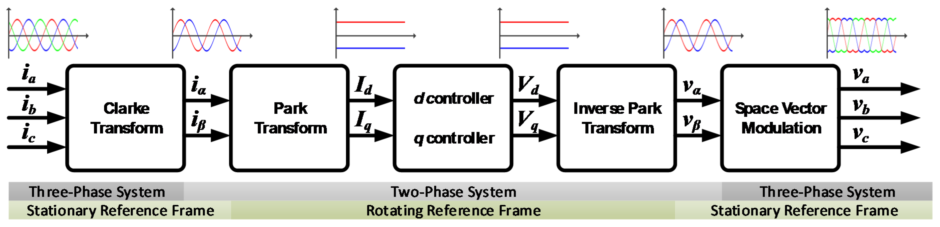
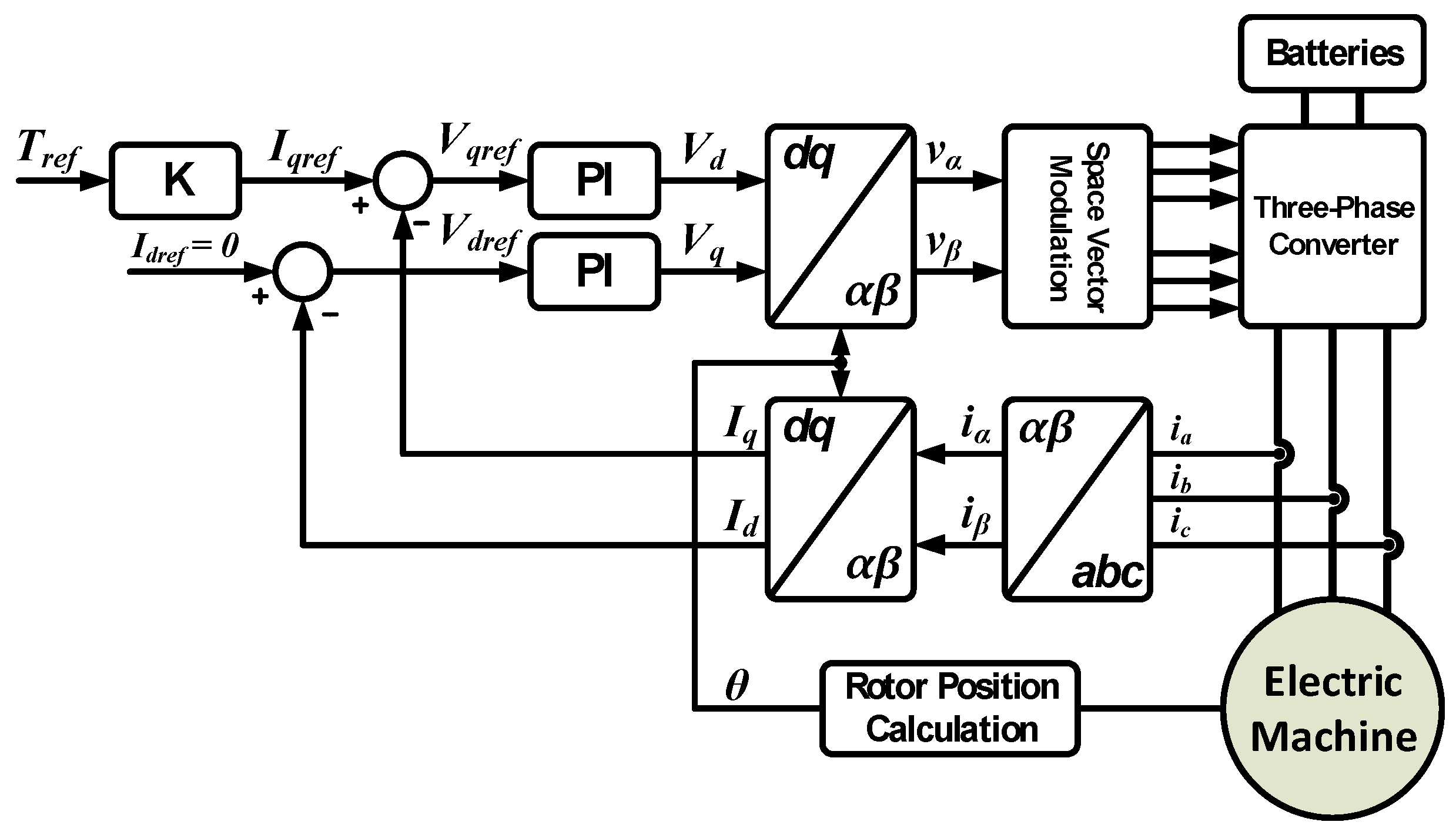
3.1. Operation in Traction Mode

With the aim of controlling the proposed unified power converter in traction mode, field-oriented control (FOC) was chosen. FOC has the advantages of low distortion and torque ripple, and it allows operation with a fixed switching frequency. FOC decomposes the stator currents of the electric machine into the dq rotational reference frame. The direct component (d) allows the adjustment of the stator flux value, while the quadrature component (q) adjusts the torque value. The components are independently controlled, consequently allowing control of the electric machine as a separately excited direct current motor [30,31]. For a permanent magnet synchronous machine, the maximum torque is obtained when the reference Idref is zero [32].
Figure 8 presents the typical block diagram of FOC. In the presented control, velocity is used as a reference variable, which can be used to implement the cruise control function. However, for controlling the electric machine in powertrain systems, torque control is more usual, where the reference torque is obtained from the throttle pedal position of the EV [31].
To implement FOC, it is essential to have knowledge of the stator winding currents and the rotor position of the electric machine. When it is not possible to incorporate a rotor position sensor in the electric machine, the rotor position can be obtained from estimation methods. This control is denominated as sensorless FOC [33,34,35,36]. Figure 9 presents the conversion stages and axes system used in FOC.
The three electric machine currents (ia, ib, and ic) are converted into a two-dimensional stationary coordinate system through the Clarke transform. The two obtained components (iα and iβ) are 90° phase-shifted. If the system is balanced, only two currents can be used as input, since the sum of the three currents is zero. Afterward, the Park transform uses the two signals obtained from the Clarke transform and converts them to a rotational system. The output signals (id and iq), as mentioned above, are used to control the values of stator torque and flux. The inverse Park transform converts the signals back to a stationary system, where the signals vα and vβ are obtained. These signals are used as inputs for a space vector modulation (SVM) block.

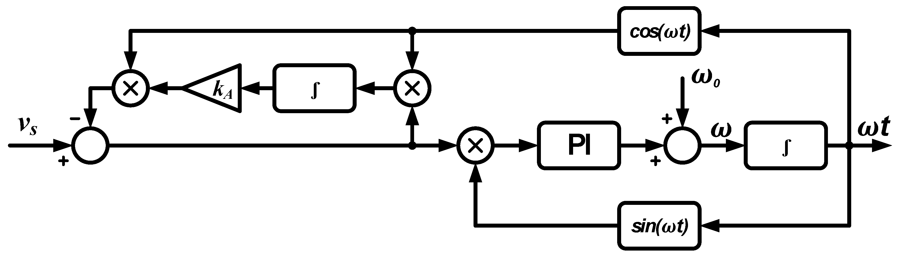
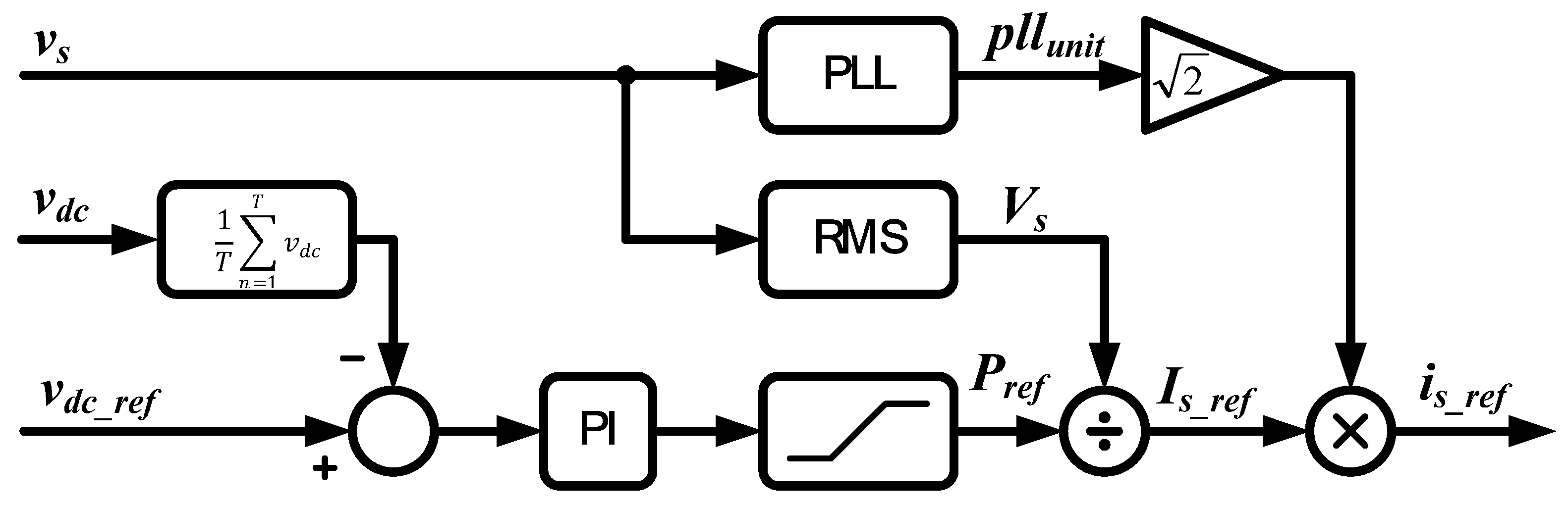
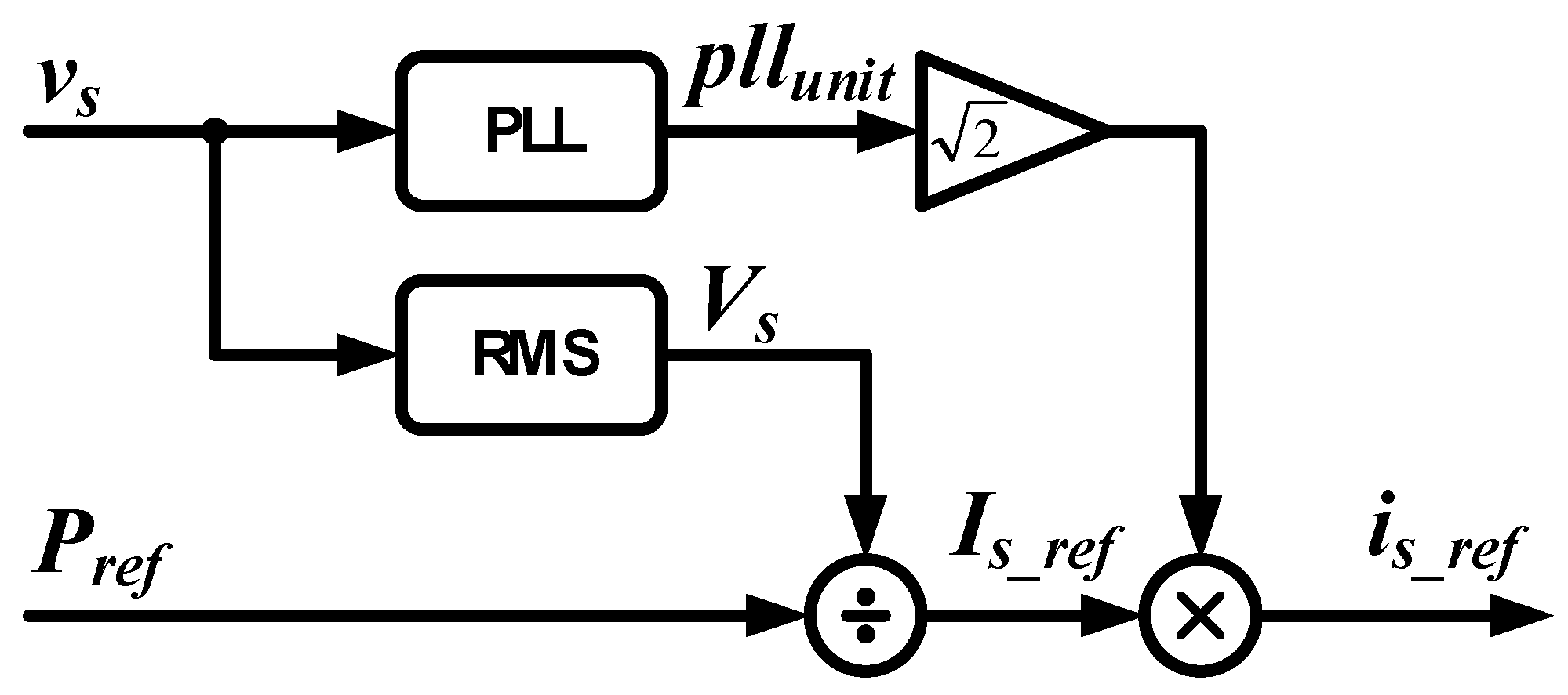
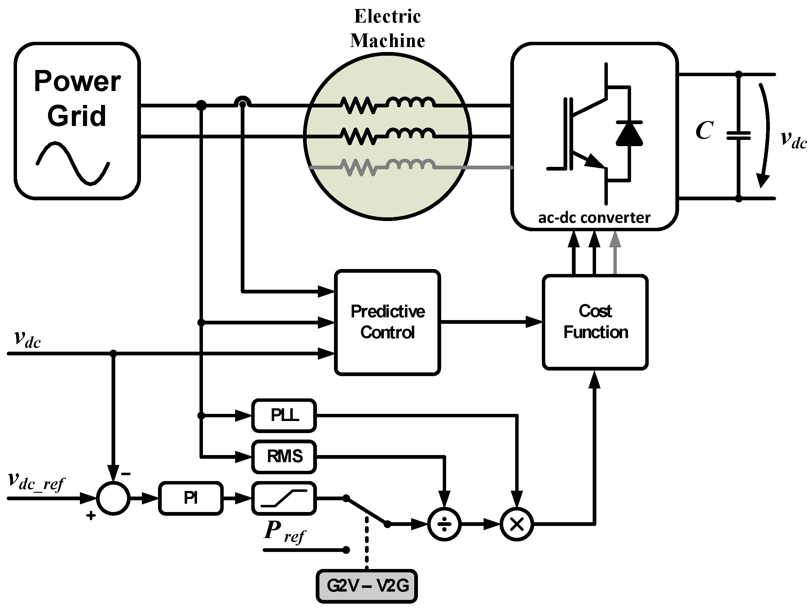
3.2. Operation in Battery-Charging Mode

A synchronization algorithm, in battery-charging mode, is necessary between the power grid voltage and the power converter. This process is important for the implementation of power quality control strategies [38], since the connection of nonlinear loads to the power grid creates imbalances and harmonic distortion in the currents and voltages of the power grid. The most used algorithm to achieve the referred synchronization is the phase-locked loop (PLL). This algorithm consists of a feedback control system that presents as a final result a sinusoidal signal in phase with the power grid voltage [39,40].
Karimi-Ghartemani et al. proposed an enhanced phase-locked loop (EPLL), whose block diagram is presented in Figure 10 [41,42] and used in this paper. The EPLL does not only guarantee phase synchronization of the signal but also calculates the amplitude of the fundamental component of the power grid voltage [42].
Cortes et al. proposed a finite control set model predictive control (FCS-MPC) that is referred to as direct power control based on model predictive control (DPC-MPC) to control three-phase ac–dc power converters [44].
The following equation gives the dynamic model of the three-phase ac–dc power converter [44]:
v s ( t ) = v R ( t ) + v L ( t ) + v i n ( t ) = R s   i s ( t ) + L s   d i s ( t ) d t + v i n ( t )   ,
where vR(t) is the voltage drop in the internal resistance of the inductor, vs(t) is the power grid voltage, vL(t) is the inductor voltage, vin(t) is the voltage generated by the converter, is(t) is the grid current, Rs is the internal resistance of the inductor, and Ls is the inductance value of the inductor. By isolating the derivative part of Equation (1), the following equation is obtained:
d i s ( t ) d t = 1 L s [ v s ( t ) R s   i s ( t ) v i n ( t ) ]   .
The dynamic model can be discretized by approximating the derivative as the difference over a sampling period (Ts) [44]:
d i s ( t ) d t = i s ( k + 1 ) i s ( k ) T s   .
Therefore, the estimated grid current is described for the sampling period by [44]:
i s [ k + 1 ] = ( 1 R s   T s L s )   i s [ k ] + T s L s [ v s [ k ] v i n [ k ] ]   .
With the use of a sampling frequency with a high value compared to the frequency of the voltages and currents, it can be assumed that the voltage at the instant [k + 1] is similar to the voltage at the instant [k], according to [44]:
v s [ k + 1 ] v s [ k ]   .
The current value is obtained by adding a step to Equation (4), where the following equation is obtained [44]:
i s [ k + 2 ] = ( 1 R s   T s L s )   i s [ k + 1 ] + T s L s [ v s [ k + 1 ] v i n [ k + 1 ] ]   .
When the EV is plugged into a single-phase power grid, the cost function commonly used in [45,46] is applied, which consists of minimizing the grid current error, which is designated by:
g = | i s _ r e f i s [ k + 2 ] |   .
Pinto et al. propound a single-phase bidirectional battery charger for EVs. Figure 11 presents the block diagram used to obtain the reference current in G2V mode [47].
In V2G operating mode, part of the energy stored in the batteries is delivered back to the power grid. In this sense, the reference power (Pref) assumes negative values. Figure 12 shows the block diagram for obtaining the reference current in V2G operating mode [47].
The block diagram in Figure 13 presents the proposed slow battery-charging strategy for the unified power converter. In slow battery-charging mode, only two legs of the proposed unified power converter are used.

4. Simulation Results

The motor drive and battery-charging system simulation results are presented in this section. As mentioned before, FOC for traction mode and MPC for battery-charging mode were chosen.
The simulations allow understanding the implemented model, and they anticipated the challenges that can occur in the experimental validation. The presented simulations were performed using PSIM software.

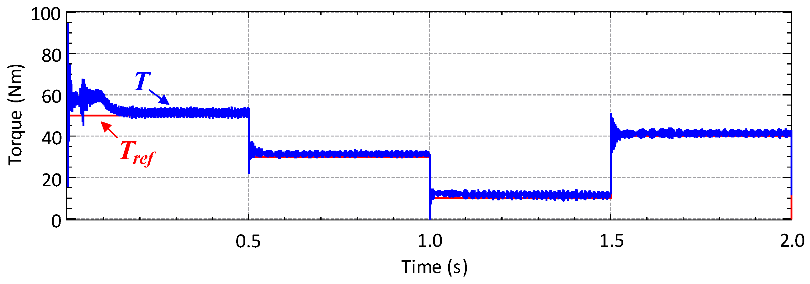
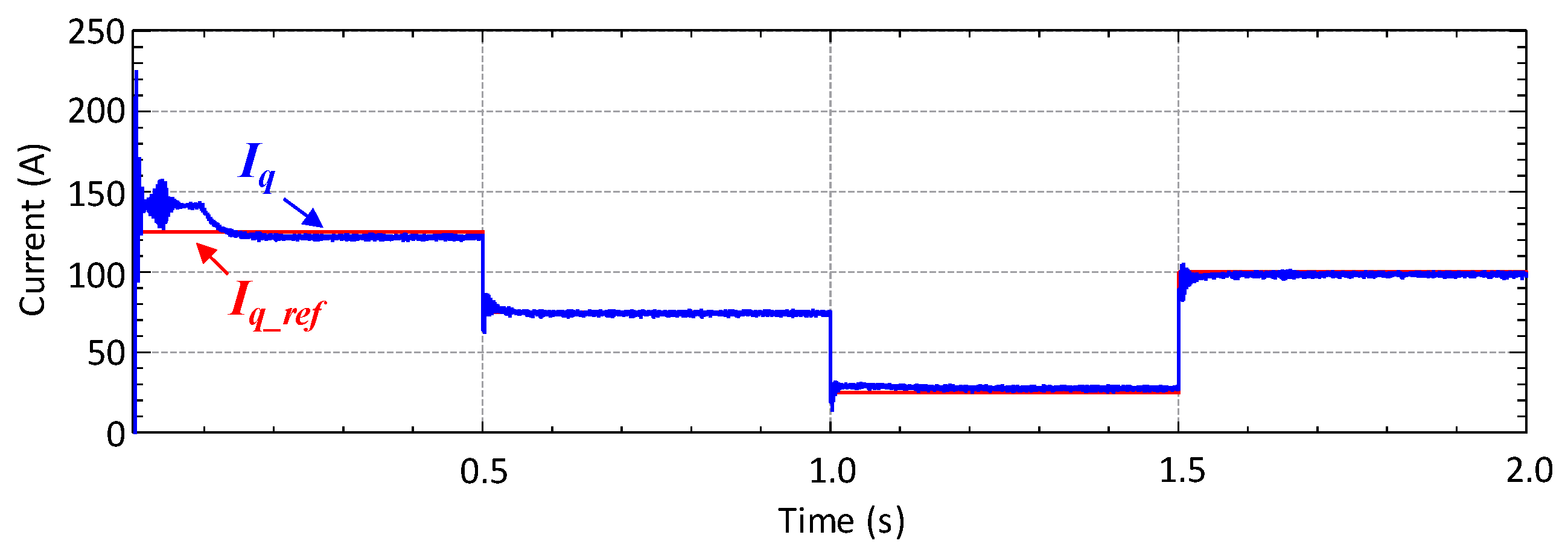
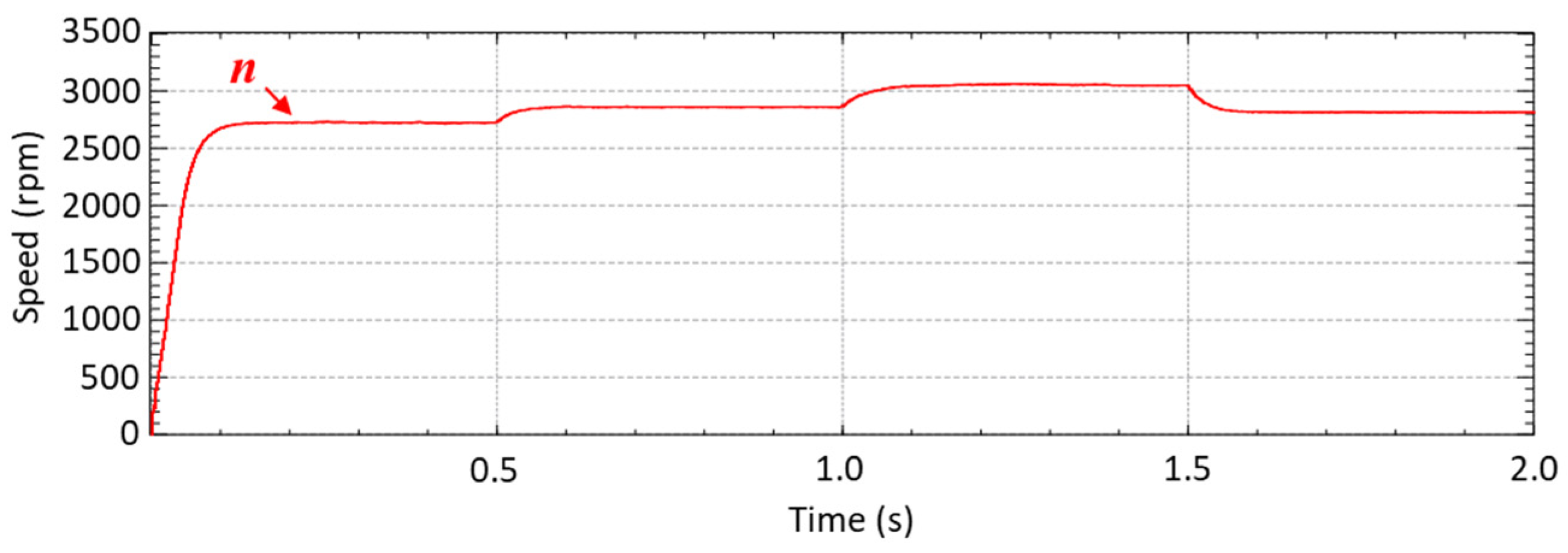
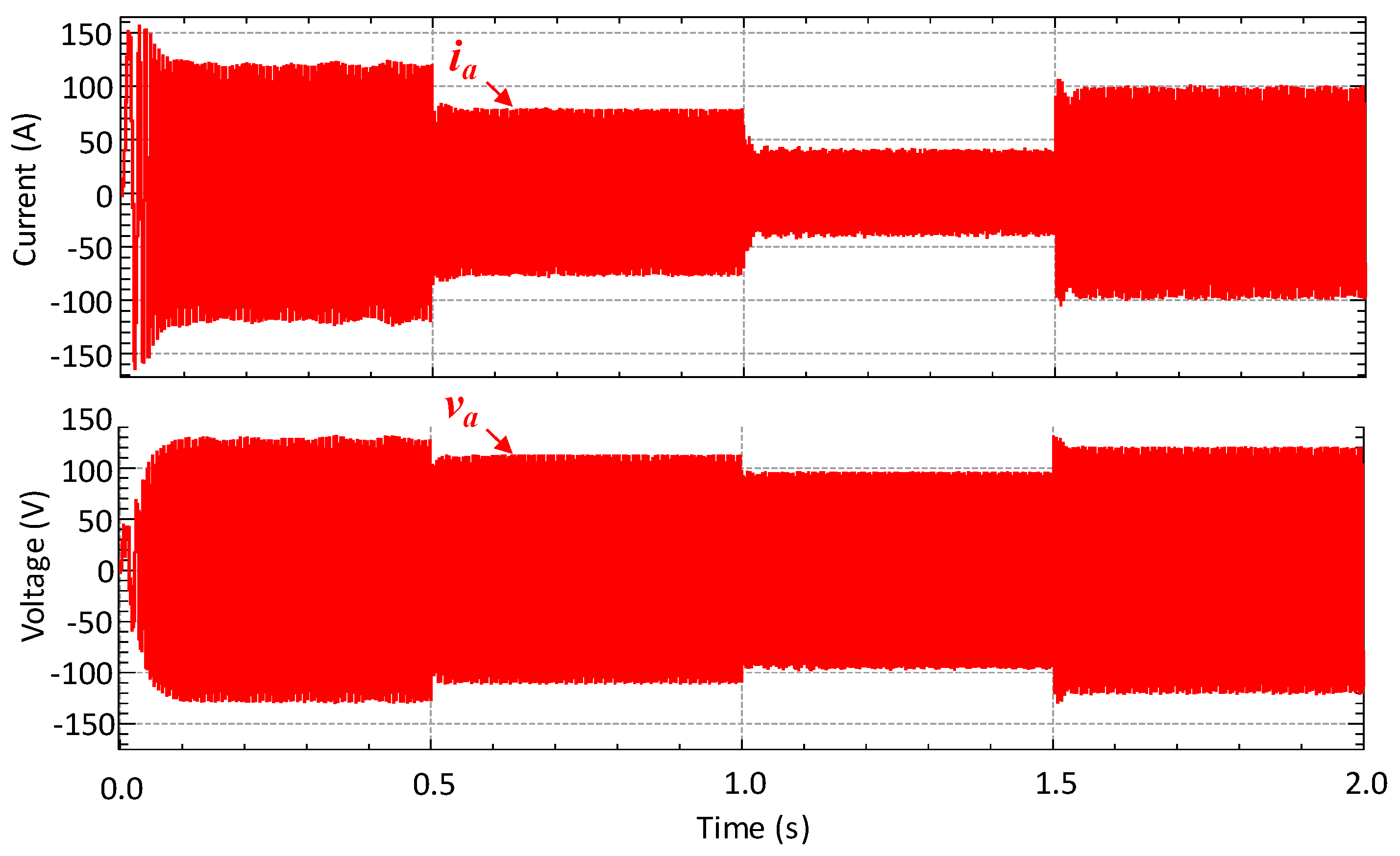
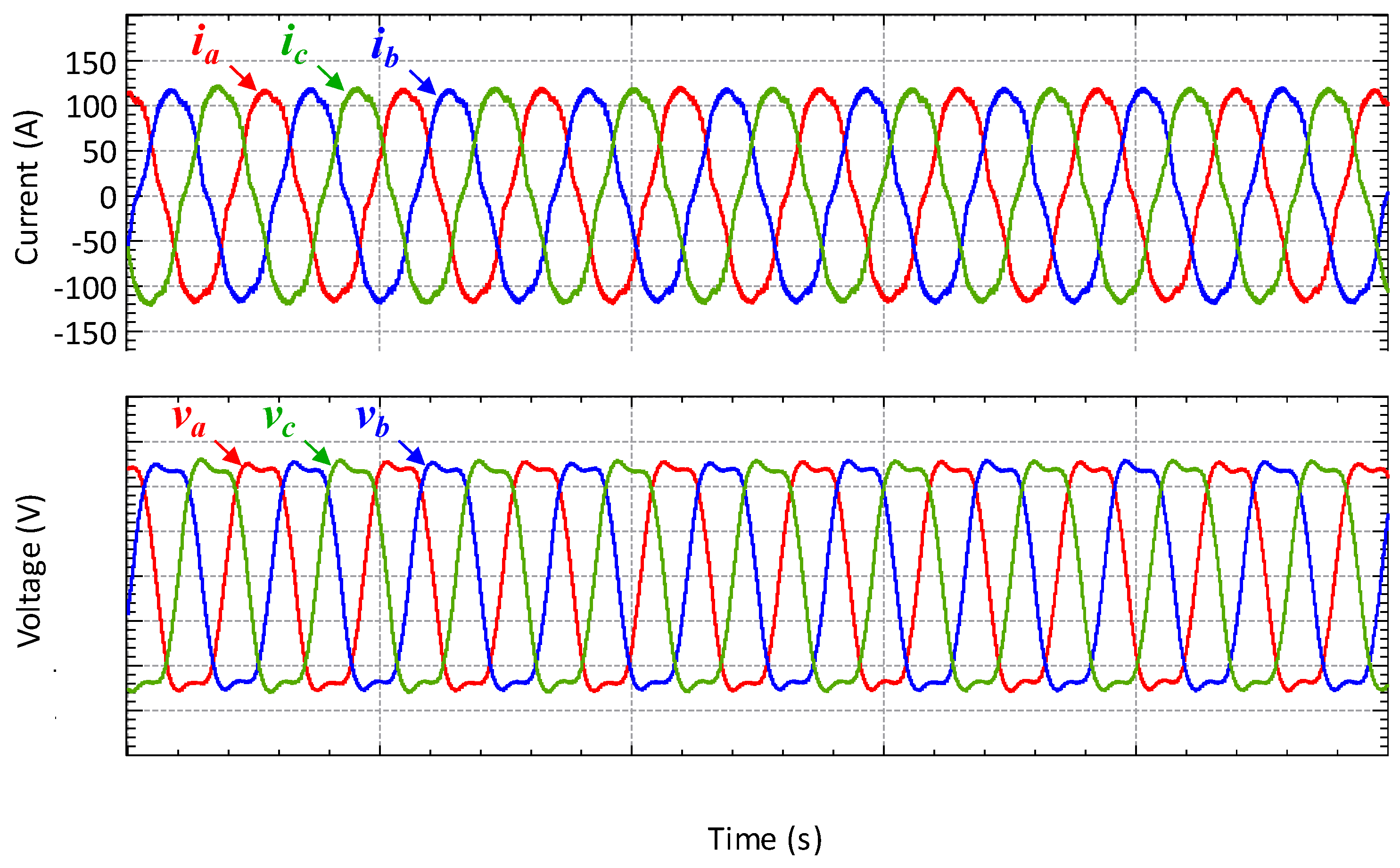
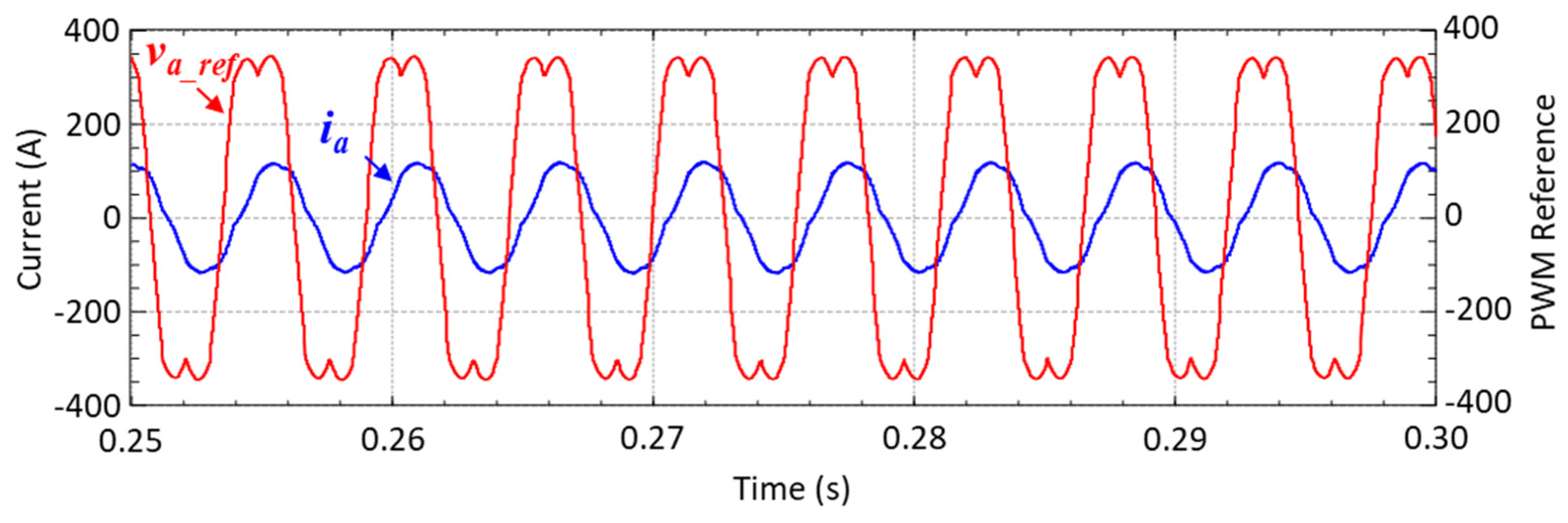
4.1. Operation in Traction Mode

Figure 14 presents the block diagram of the implemented FOC with SVM. As previously mentioned, the reference variable for the implemented control is the torque that the electric machine must produce. In EVs, the reference torque is obtained from the position of the throttle pedal. With this electric machine, the reference torque from the throttle pedal varies between 0 and 50 Nm (nominal torque of the electric machine).
The parameters of the brushless dc (BLDC) electric machine used in the simulation are presented in Table 2.
Here are presented different simulation results with different values of a mechanical load coupled in the rotor shaft in traction mode. Up to 0.5 s, a load of 50 Nm was defined; between 0.5 and 1.0 s, a load of 30 Nm was defined; between 1.0 and 1.5 s, a load of 10 nm was defined; and between 1.5 and 2.0 s, a 40 nm load was defined.
In Figure 15 are presented the reference torque (Tref) and the torque produced by the electric machine (T) for the abovementioned values of mechanical load.
In Figure 16 are presented the control signals for different values of the mechanical load obtained from the control system, namely the q-axis reference current and produced current (Iq_ref and Iq, respectively). The value of Iq_ref corresponds to the reference torque value multiplied by a constant. It should be noted that a null reference current was set for the d-axis, where the maximum available torque is obtained with the minimum amplitude of stator current.
By analyzing the waveforms presented in Figure 16, it can be concluded that the value of Iq, as expected, is proportional to the torque produced by the electric machine.
Figure 17 shows the evaluation of the electric machine speed (n) for different mechanical load values applied to the rotor shaft, where a fast response of the control system to the torque variation required by the mechanical load can be seen. The ripple of the rotation speed in the steady state is practically null. For instance, for a rotation speed of 2720 rpm, the maximum ripple is 15 rpm. For the same condition, the torque has a maximum ripple of 6 nm when the mechanical load required is 50 nm.
Figure 18 presents the voltage (va) and current (ia) in phase a of the electric machine stator winding for the mechanical load values mentioned above. As can be seen in Figure 16, Figure 17 and Figure 18, the speed of the electric machine is proportional to the stator voltage value, while the torque is directly proportional to the currents absorbed by the electric machine.
Figure 19 shows the detail of the waveforms of the currents and voltages, in each phase, absorbed by the electric machine when it has a mechanical load of 50 nm. The absorbed currents have an RMS value of 84 A, and the voltages have an RMS value of 102 V.
In Figure 20 are presented the reference modulation signal (ta_ref) and the current (ia) in phase a when the electric machine operates with a nominal mechanical load. A low-pass filter with a 1 kHz resonant frequency is applied for the reference signal.
By analyzing the phase shift between ta_ref and ia, it is concluded that the current has a phase delay of 40° relative to the reference signal when the electric machine operates with a nominal mechanical load. This phase shift occurs due to the intrinsically resistant torque of the system and electric machine inductance.

4.2. Operation in Battery-Charging Mode

The battery-charging mode is performed for slow battery charging. In both situations (G2V and V2G modes), the power factor is near the unity and the grid current is sinusoidal.
In slow battery-charging mode, only two legs of the three-phase power converter are used because it is used a single-phase connection with the power grid. An extra inductor is added in series with the power grid because it is observed that the inductance value of the electric machine windings is low. Table 3 presents the simulation parameters used in G2V mode.
To ensure the power quality from the power grid perspective, a synchronization process between the power grid and the power converter is required. In this sense, Figure 21a shows the PLL results for a single-phase voltage (va) with a harmonic distortion similar to that of the power grid voltage. The voltage has a total harmonic distortion (THD) of 4.7%. The PLL algorithm was implemented in C language, with a sampling frequency of 40 kHz. The PLL synchronizes with the power grid voltage after some cycles. Figure 21b shows the evolution of the angle ωt. Figure 22 shows a detail of the synchronism (between the power grid and the PLL) during two cycles of the power grid voltage.
G2V slow battery-charging mode is started after synchronism with the power grid is obtained. Figure 23 shows the dc-link voltage regulation to 350 V. A pre-charge was performed until the dc-link voltage (vdc) reached 290 V, which occurs at approximately 2 s. After this time, the control algorithm comes into operation and a load of 1.5 kW is connected. The dc-link voltage in the steady state has a ripple of around 0.9%.
Figure 24 presents the simulation results of the absorbed current (ia), the reference current (ia_ref), and the power grid voltage (va) during G2V operation. As it is possible to verify, the current in the power grid is sinusoidal and in phase with the voltage. During the pre-charge process, the absorbed current has the typical characteristics of the current consumed by a single-phase bridge rectifier with a capacitive filter. This happens because the ac–dc converter is not active during the pre-charge process, acting as a passive diode rectifier. After this process (t > 2 s), the control system is activated, and the absorbed current is sinusoidal and in phase with the power grid voltage. In the steady state, the current absorbed from the power grid has an RMS value of 7.4 A and a THD of 16%.
The following simulation results were obtained in V2G operating mode. Figure 25 presents the reference current (ia_ref), the current supplied to the power grid by the EV battery (ia), and the power grid voltage (va). The current supplied to the power grid has an RMS value of 6.7 A and a THD of 18%.

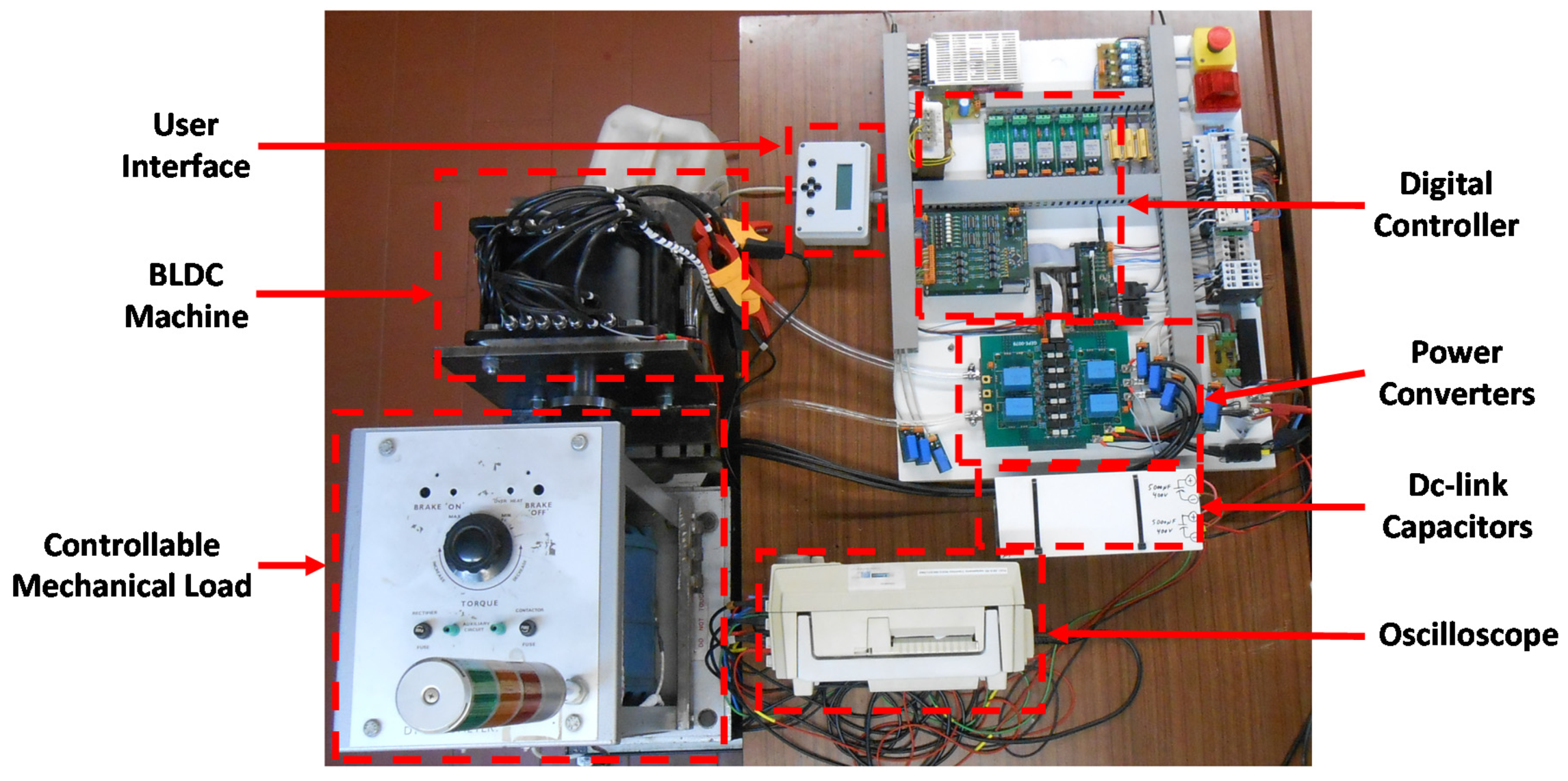
5. Experimental Validation

In this section, the experimental validation of the propounded unified power converter is presented. As mentioned before, the presented results refer only to the ac–dc power converter. In traction mode, a test bench was used to apply different mechanical loads to the electric machine. The test bench allows the coupling of different types of electric machines to an electromagnetic brake. It is possible to adjust the applied torque between 0 and 47 Nm. To ensure that the obtained results were as accurate as possible, the test bench was calibrated according to the procedure described in [48]. In battery-charging mode, resistors were used as a load, instead of batteries. Transformers were also used to test the system with galvanic isolation and with low voltage values.
The laboratorial prototype of the proposed unified power converter is presented in Figure 26. The experimental results presented in this section were obtained using the Yokogawa DL708E oscilloscope.

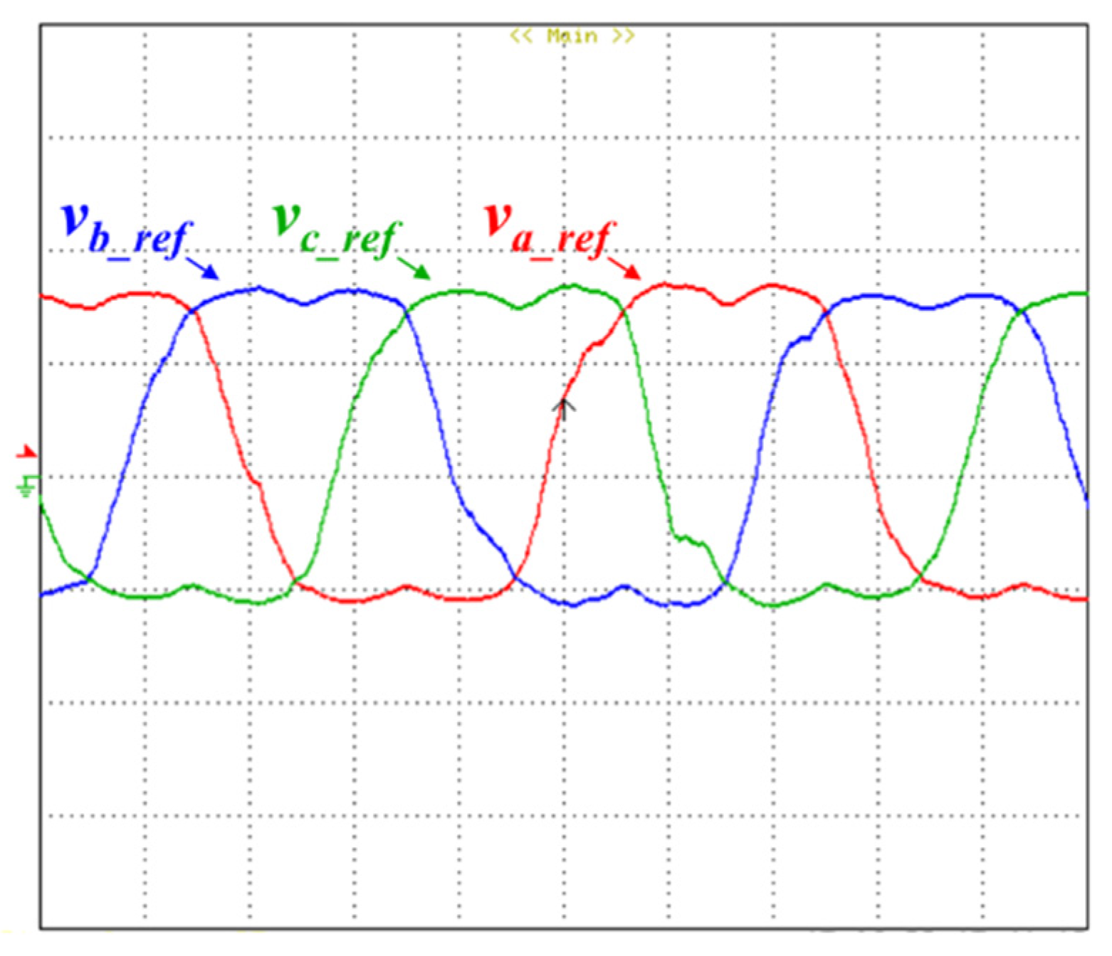
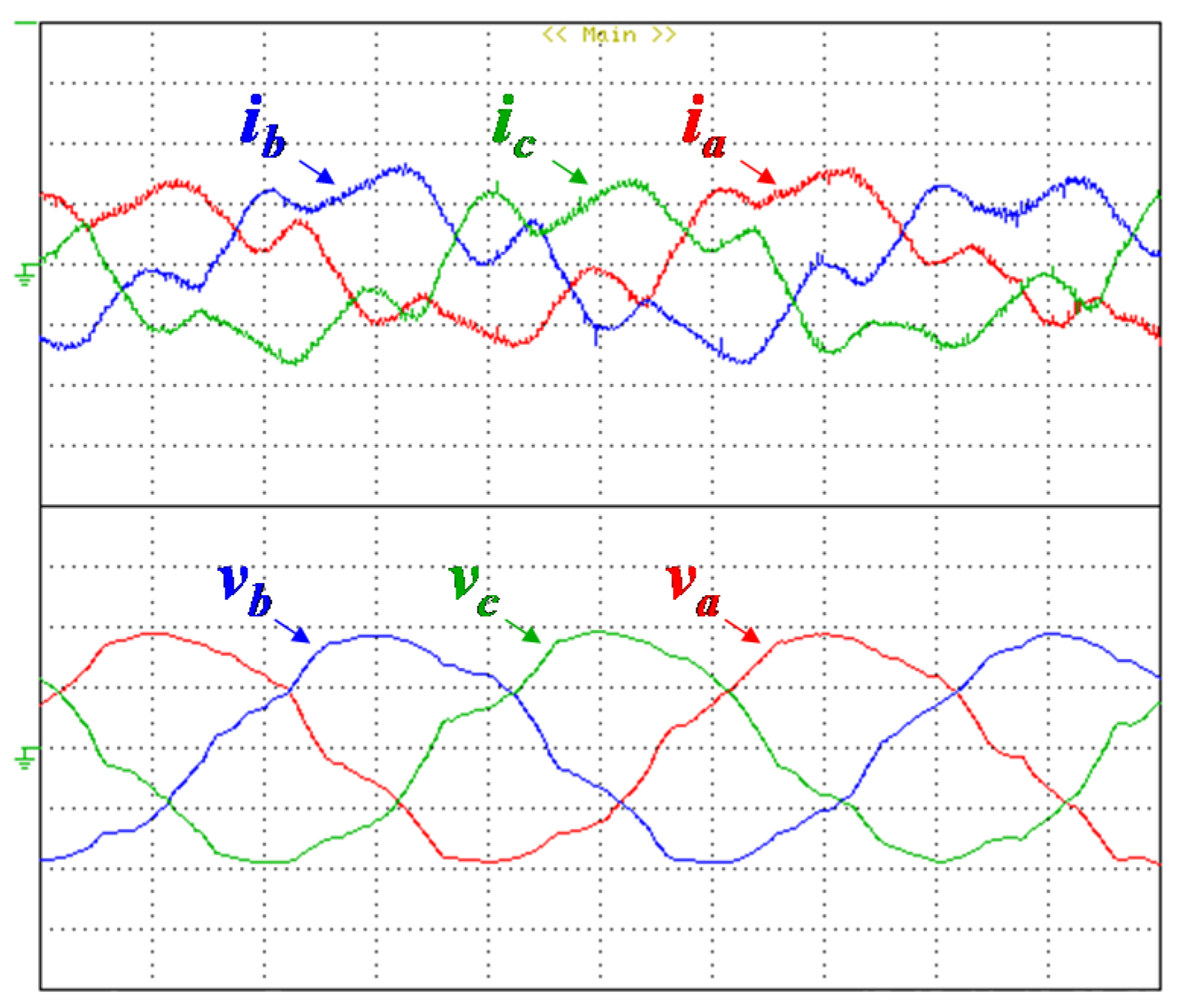
5.1. Operation in Traction Mode

In this subsection, experimental results obtained for the operation of the electric machine with different coupled mechanical loads are presented. Due to the limits of the test bench, the maximum mechanical load was limited to 45 nm. Figure 27 shows the reference signals (ta_ref, tb_ref, and tc_ref) applied to the three legs of the power converter when a mechanical load of 9 Nm is applied to the electric machine. To present the signals, a 500 Hz resonance frequency digital low-pass filter was applied. The cut-off frequency was selected from the settings of each oscilloscope channel. For this mechanical load, the electric machine has a rotation speed of 500 rpm.
Figure 28 presents the three-phase voltages (va, vb, and vc) and currents (ia, ib, and ic) supplied to the electric machine with a mechanical load of 9 Nm in the steady state. The three-phase voltages and currents have an RMS value of 27 V and 12.2 A, respectively.
Figure 29 shows the reference signal applied to phase a (ta_ref) of the power converter and the current in the same phase (ia) when the electric machine operates with a mechanical load of 9 Nm. By analyzing both waveforms, it can be seen that the phase shift between them is practically null.
Figure 30 shows the reference signals (ta_ref, tb_ref, and tc_ref) applied to the three legs of the power converter when a mechanical load of 45 Nm is applied to the electric machine. For this mechanical load, the electric machine has a rotation speed of 310 rpm.
Figure 31 presents the three-phase voltages (va, vb, and vc) and currents (ia, ib, and ic) supplied to the electric machine with a mechanical load of 45 nm in the steady state. The three-phase voltages and currents have an RMS value of 18 V and 38.7 A, respectively.
Figure 32 shows the reference signal applied to phase a (ta_ref) of the power converter and the current in the same phase (ia) when the electric machine works with a mechanical load of 45 nm. By analyzing the obtained waveforms, it is verified that there is a 13° phase shift between them.
Due to the limits of the test bench, the tests were performed with a maximum torque of 45 Nm. As expected, with the increase in the applied mechanical load, the nominal current also increased and the current distortion reduced.

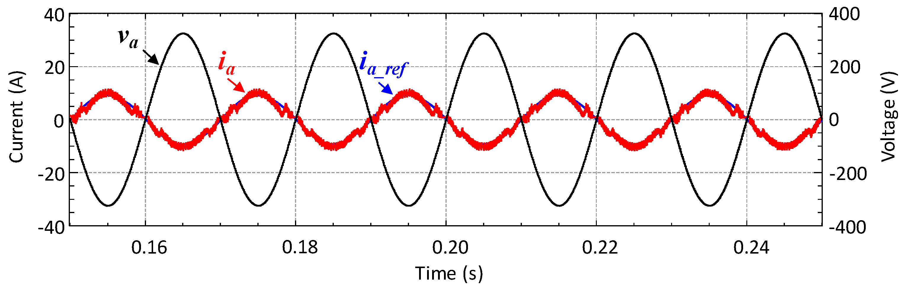
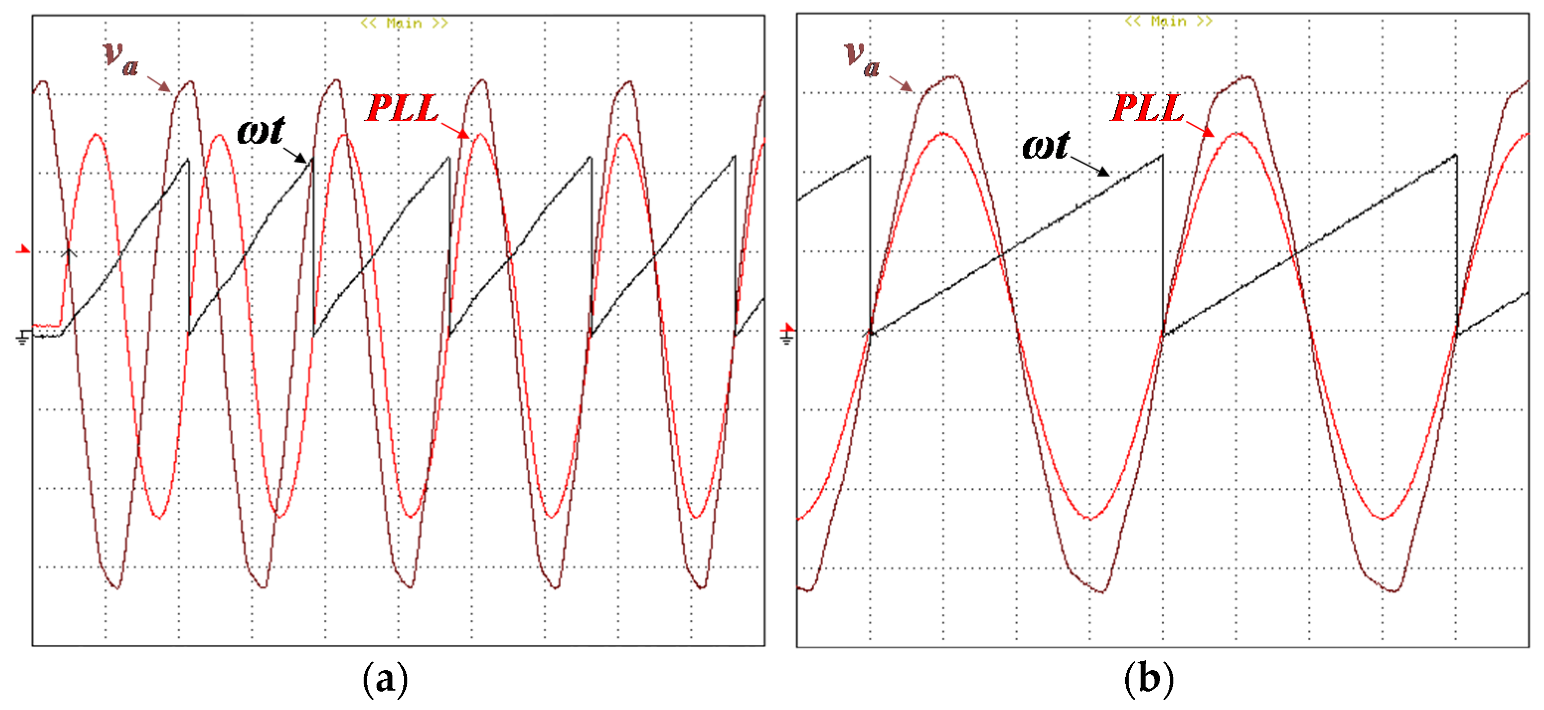
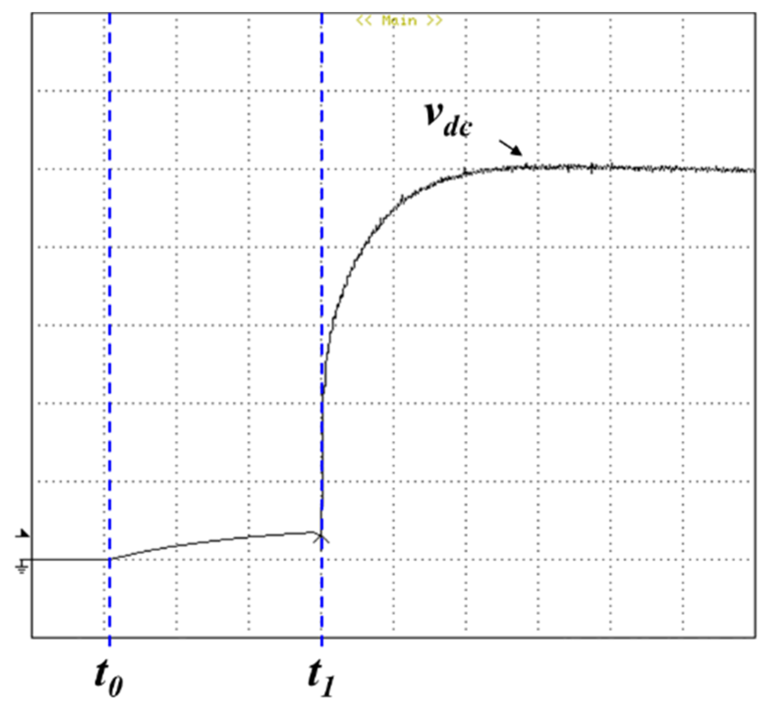
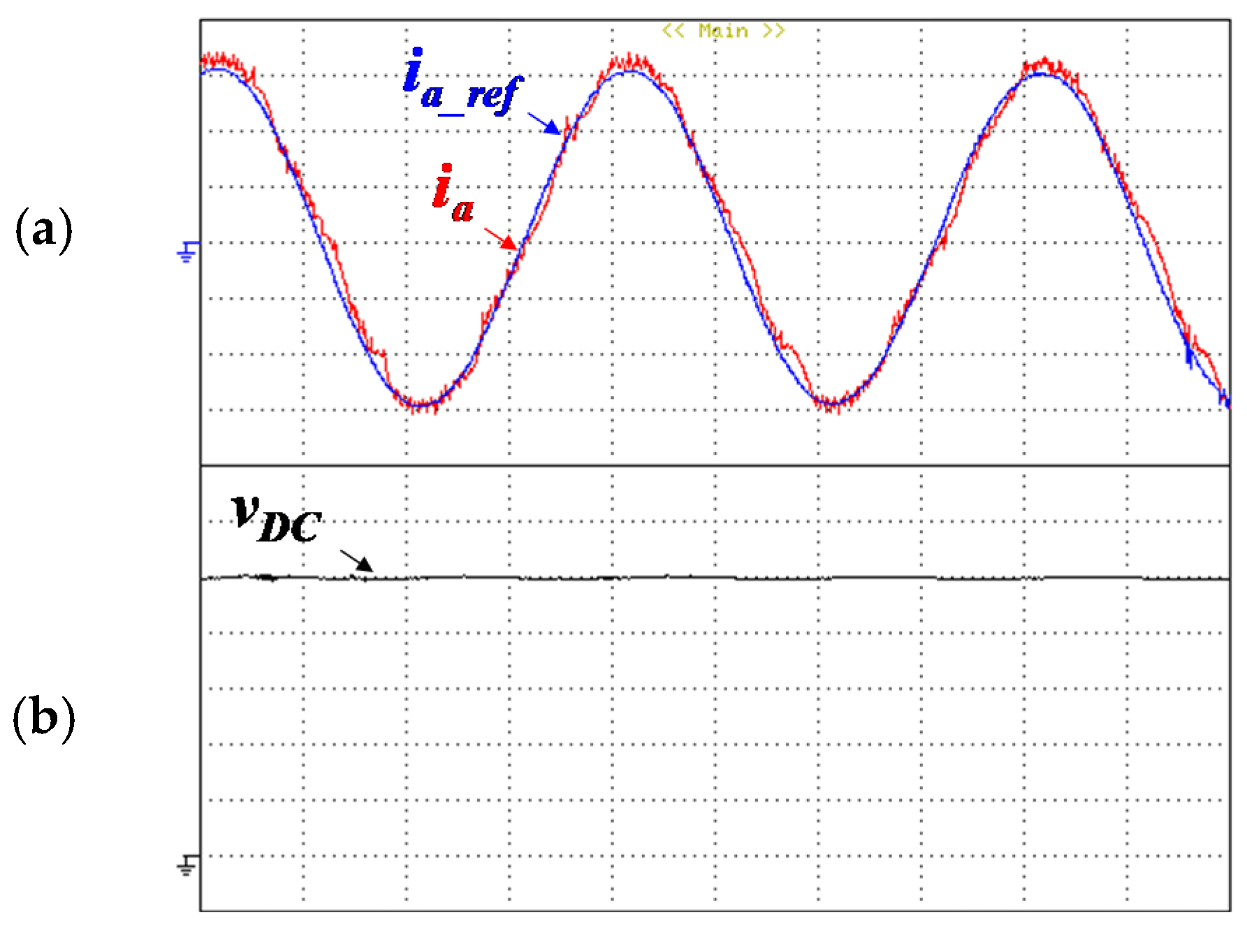
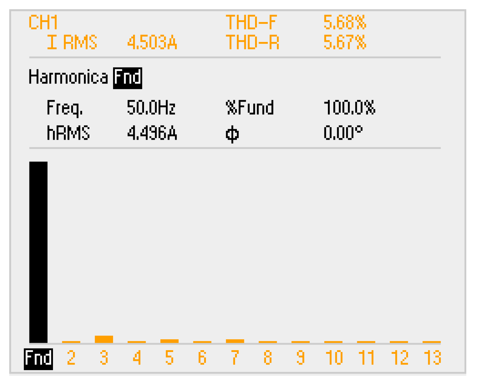
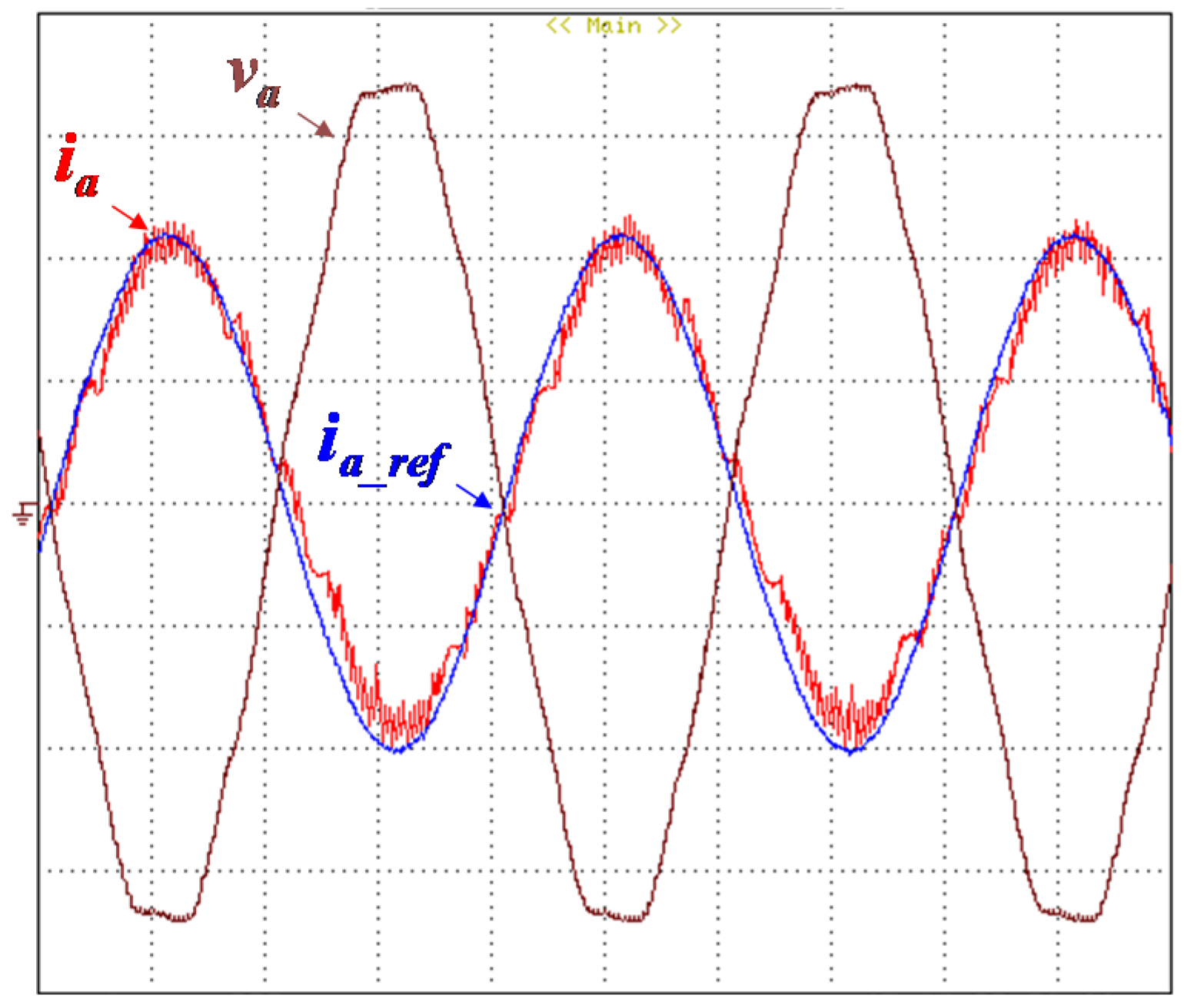
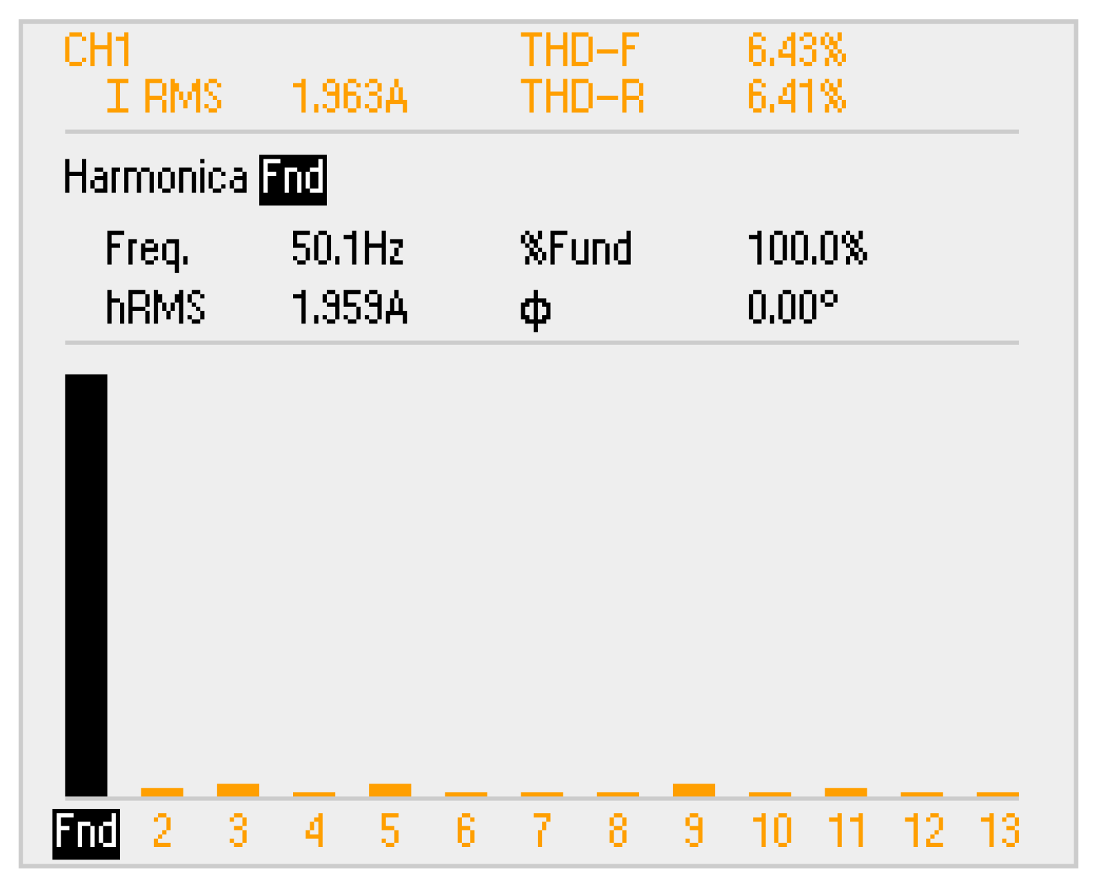
5.2. Operation in Battery-Charging Mode

This subsection shows the experimental validation of the slow battery-charging system. The tests were carried out for a single-phase voltage with an RMS value of 50 V. This voltage is obtained from an 11 kVA single-phase transformer (230–50 V). The transformer is used to decrease the RMS voltage of the power grid, and additionally, it allows operating with isolation from the power grid.
As mentioned before, a control algorithm that detects the phase of the power grid voltage is required. Thus, the first results presented in this subsection are related to the PLL. Figure 33 shows the power grid voltage (va), the PLL output signal, and the evolution of the angle ωt. Figure 33a presents the synchronization process with the power grid; it was possible to verify that it takes about four cycles. This synchronization does not need to be faster, because this process occurs in parallel with others. In Figure 33b, is possible to see that the PLL is in phase with the power grid voltage and its waveform is sinusoidal, even with some distortion existing in the power grid voltage.
When the EV is plugged into the power grid, it is possible that the dc-link capacitors are discharged. Therefore, a pre-charge of the dc-link voltage is essential. Figure 34 shows the dc-link voltage (vdc) during the pre-charge process and the power converter start operation. At time t0, the dc-link pre-charge is started until the voltage reaches 10 V (time t1). From this time instant, the control algorithm is started.
Figure 35 presents the grid current (ia), the respective reference (ia_ref), and the dc-link voltage (vdc), in the steady state, in G2V mode. The presented results were obtained for a 100 V dc-link reference voltage. The current absorbed from the power grid follows the reference current but still has some harmonic content. The characteristics and harmonic spectrum of the grid current in G2V mode when performing slow battery charging are presented in Figure 36. The current has a THD of 5.68% and an RMS value of 4.5 A.
Figure 37 shows the power grid voltage (va), current (ia), and reference current (ia_ref), in the steady state, in V2G mode. The results were obtained with 100 V of dc-link voltage. It can be observed that the current supplied to the power grid follows the reference current. In this operation mode, the reference current is in opposite phase with the power grid voltage. The characteristics and harmonic spectrum of the supplied current in V2G mode are presented in Figure 38. The current has a THD of 6.43% and an RMS value of 1.96 A.

6. Conclusions

This paper proposes a unified power converter for electric vehicles (EVs). The unification is possible because the operation in motor drive mode and the operation in battery-charging mode do not occur simultaneously. Thus, the proposed unified power converter can be controlled to execute distinct functionalities, permitting the operation as motor drive, regenerative braking, and slow or fast battery charging. In traction mode, the unified power converter operates with bidirectional power flow to support motor driving and regenerative braking. Similarly, when the EV is stopped and connected to the electrical power grid, the unified power converter can also operate in bidirectional mode, having the function of controlling the power flow between the EV batteries and the power grid, in grid-to-vehicle (G2V) or in vehicle-to-grid (V2G) mode.
Regarding the operation modes, specifically, this paper presents computer simulations and experimental validations obtained for three operation modes: motor drive and slow battery charging in G2V and V2G modes. However, in the future, the proposed unified power converter will be validated with other operation modes under computer simulations and experimental validations.
In terms of control algorithms, during the motor drive operation, field-oriented control (FOC) is used, and during the slow battery-charging operation, model predictive control (MPC) is used. Results of the traction mode with FOC are presented for different values of mechanical load, showing fast response of the reference torque variation and good performance, with or without mechanical load. The results were obtained with a maximum mechanical load of 45 Nm.
In slow battery-charging mode, two different types of operation were presented: in G2V mode, the EV batteries are charged with sinusoidal grid currents, in phase with the power grid voltages; in V2G mode, the power grid receives part of the stored energy from the EV batteries, also with sinusoidal grid currents, but in phase opposition with the power grid voltages. In both cases, it is demonstrated that the unified power converter operates with high levels of power quality.

Author Contributions

D.P. performed the literature review analysis, design, testing and validating of the laboratory prototype explained in this paper, and writing—original draft preparation. All authors participated in the conceptualization, methodology, and writing—review and editing. All authors have read and agreed to the published version of the manuscript.

Funding

This work was supported by the Portuguese Foundation of Science and Technology (FCT) (in Portuguese, Fundação para a Ciência e Tecnologia) within the R&D Units Project Scope: UIDB/00319/2020. This work was also supported by the FCT Project DAIPESEV PTDC/EEI-EEE/30382/2017 and by the FCT Project newERA4GRIDs PTDC/EEI-EEE/30283/2017. T.J.C.S. is supported by the doctoral scholarship SFRH/BD/134353/2017 granted by the FCT.

Conflicts of Interest

The authors declare no conflict of interest.

References

  1. Woo, D.-G.; Kim, Y.-S.; Lee, B.-K. Effect of PWM schemes on integrated battery charger for plug-in hybrid electric vehicles: Performance, power factor, and efficiency. In Proceedings of the 2014 IEEE Applied Power Electronics Conference and Exposition—APEC 2014, Fort Worth, TX, USA, 16–24 March 2014; pp. 3243–3248. [Google Scholar]
  2. Haghbin, S.; Lundmark, S.; Alakula, M.; Carlson, O. Grid-Connected Integrated Battery Chargers in Vehicle Applications: Review and New Solution. IEEE Trans. Ind. Electron. 2012, 60, 459–473. [Google Scholar] [CrossRef]
  3. Afonso, J.L.; Cardoso, L.A.L.; Pedrosa, D.; Sousa, T.J.C.; Machado, L.; Tanta, M.; Monteiro, V. A Review on Power Electronics Technologies for Electric Mobility. Energies 2020, 13, 6343. [Google Scholar] [CrossRef]
  4. Monteiro, V.; Afonso, J.A.; Ferreira, J.C.; Afonso, J.L. Vehicle Electrification: New Challenges and Opportunities for Smart Grids. Energies 2019, 12, 118. [Google Scholar] [CrossRef] [Green Version]
  5. Yilmaz, M.; Krein, P.T. Review of the Impact of Vehicle-to-Grid Technologies on Distribution Systems and Utility Interfaces. IEEE Trans. Power Electron. 2013, 28, 5673–5689. [Google Scholar] [CrossRef]
  6. Monteiro, V.; Afonso, J.A.; Sousa, T.J.; Cardoso, L.A.L.; Pinto, J.G.; Afonso, J.L. Vehicle Electrification: Technologies, Challenges, and a Global Perspective for Smart Grids. In Innovation in Energy Systems—New Technologies for Changing Paradigms; IntechOpen: London, UK, 2019. [Google Scholar]
  7. Thimmesch, D. An SCR Inverter with an Integral Battery Charger for Electric Vehicles. IEEE Trans. Ind. Appl. 1985, IA-21, 1023–1029. [Google Scholar] [CrossRef]
  8. Rippel, W.E.; Cocconi, A.G. Integrated Motor Drive and Recharge System. U.S. Patent 5,099,186, 24 March 1992. [Google Scholar]
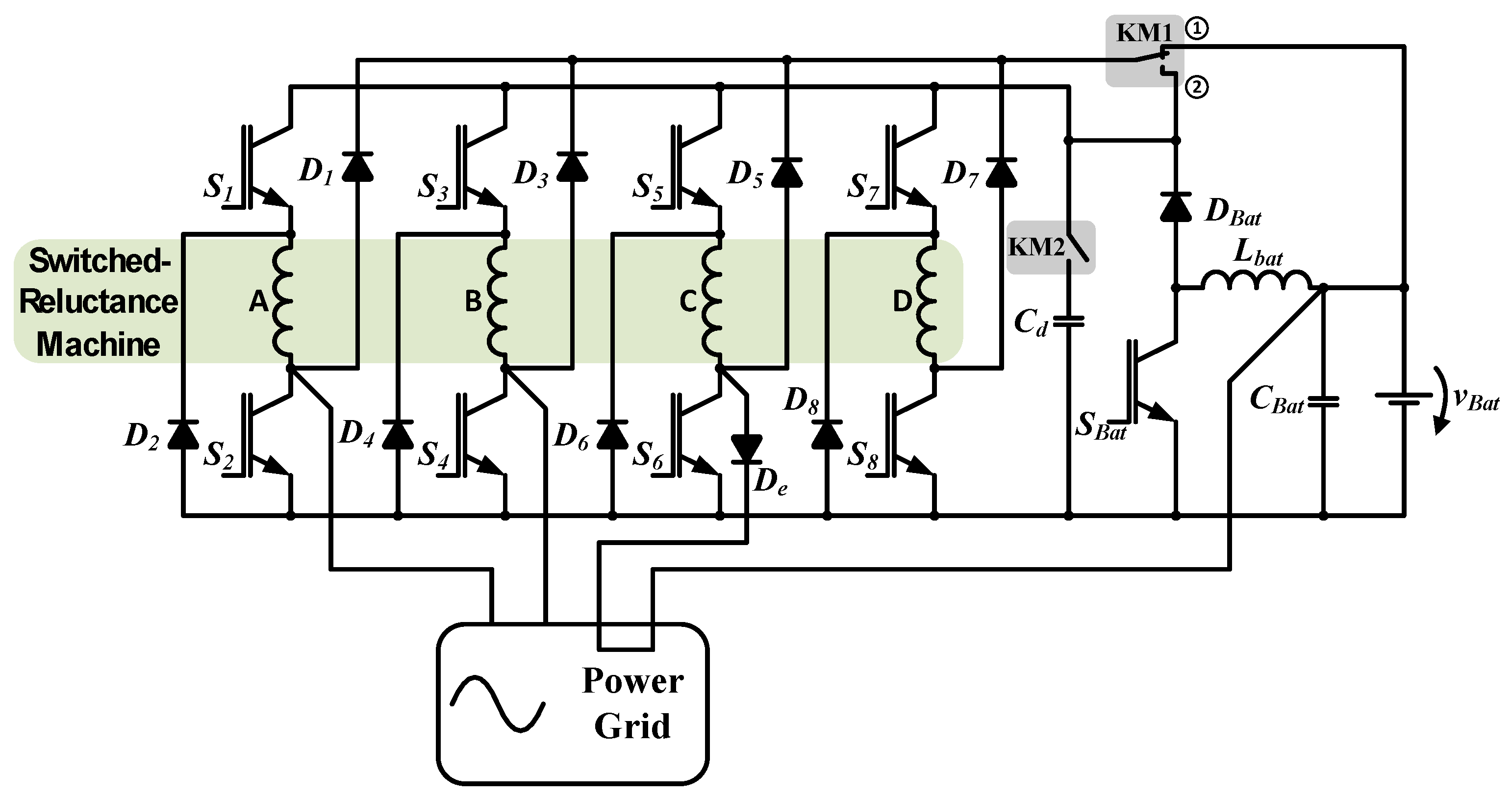
  9. Chang, H.-C.; Liaw, C.-M. Development of a Compact Switched-Reluctance Motor Drive for EV Propulsion with Voltage-Boosting and PFC Charging Capabilities. IEEE Trans. Veh. Technol. 2009, 58, 3198–3215. [Google Scholar] [CrossRef]
  10. Lacroix, S.; Laboure, E.; Hilairet, M. An integrated fast battery charger for Electric Vehicle. In Proceedings of the 2010 IEEE Vehicle Power and Propulsion Conference, Lille, France, 1–3 September 2010; pp. 1–6. [Google Scholar]
  11. Subotic, I.; Bodo, N.; Levi, E. An EV Drive-Train with Integrated Fast Charging Capability. IEEE Trans. Power Electron. 2016, 31, 1461–1471. [Google Scholar] [CrossRef] [Green Version]
  12. V, V.; Kaarthik, R.S. Modeling and Control of an Integrated Battery Charger with Split-Phase Machine. IEEE Trans. Ind. Appl. 2021, 57, 1588–1597. [Google Scholar] [CrossRef]
  13. Haghbin, S.; Guillen, I.S. Integrated motor drive and non-isolated battery charger based on the torque cancelation in the motor. In Proceedings of the 2013 IEEE 10th International Conference on Power Electronics and Drive Systems (PEDS), Kitakyushu, Japan, 22–23 April 2013; pp. 824–829. [Google Scholar]
  14. Haghbin, S.; Thiringer, T.; Carlson, O. An integrated split-phase dual-inverter permanent magnet motor drive and battery charger for grid-connected electric or hybrid vehicles. In Proceedings of the 2012 XXth International Conference on Electrical Machines, Marseille, France, 2–5 September 2012; pp. 1941–1947. [Google Scholar]
  15. Subotic, I.; Bodo, N.; Levi, E. Single-Phase On-Board Integrated Battery Chargers for EVs Based on Multiphase Machines. IEEE Trans. Power Electron. 2016, 31, 6511–6523. [Google Scholar] [CrossRef] [Green Version]
  16. Abdel-Majeed, M.S.; Eldeeb, H.M.; Metwly, M.Y.; Abdel-Khalik, A.S.; Hamad, M.; Hamdy, R.A.; Ahmed, S. Post-fault Operation of Onboard Integrated battery Charger via a Nine-Phase EV-Drive Train. IEEE Trans. Ind. Electron. 2020, 68, 1. [Google Scholar] [CrossRef]
  17. Hoevenaars, E.; Hiller, M. Conceptualization and Efficiency Review of Integrated Chargers Using Six-Phase Machines. IEEE Trans. Transp. Electrification 2021, 1. [Google Scholar] [CrossRef]
  18. Dusmez, S.; Khaligh, A. Cost effective solutions to level 3 on-board battery chargers. In Proceedings of the 2012 Twenty-Seventh Annual IEEE Applied Power Electronics Conference and Exposition (APEC), Orlando, FL, USA, 5–9 February 2012; pp. 2121–2127. [Google Scholar]
  19. Su, G.-J.; Tang, L. Current source inverter based traction drive for EV battery charging applications. In Proceedings of the 2011 IEEE Vehicle Power and Propulsion Conference, Chicago, IL, USA, 6–9 September 2011; pp. 1–6. [Google Scholar]
  20. Haghbin, S.; Khan, K.; Lundmark, S.; Alakula, M.; Carlson, O.; Leksell, M.; Wallmark, O. Integrated chargers for EV’s and PHEV’s: Examples and new solutions. In Proceedings of the The XIX International Conference on Electrical Machines—ICEM 2010, Rome, Italy, 6–8 September 2010; pp. 1–6. [Google Scholar]
  21. Haghbin, S.; Ghorbani, R.; Bermejo, A.; Guillen, I.S. An Integrated Motor Drive and Battery Fast Charger Station for Plug-in Vehicles. In Proceedings of the 13th Spanish Portuguese Conference on Electrical Engineering (13CHLIE), Valencia, Spain, 3–5 July 2013. [Google Scholar]
  22. De Sousa, L.; Silvestre, B.; Bouchez, B. A combined multiphase electric drive and fast battery charger for Electric Vehicles. In Proceedings of the 2010 IEEE Vehicle Power and Propulsion Conference, Lille, France, 1–3 September 2010; pp. 1–6. [Google Scholar]
  23. Hegazy, O.; Van Mierlo, J.; Lataire, P. Design and control of bidirectional DC/AC and DC/DC converters for plug-in hybrid electric vehicles. In Proceedings of the 2011 International Conference on Power Engineering, Energy and Electrical Drives, Malaga, Spain, 11–13 March 2011; pp. 1–7. [Google Scholar]
  24. Cocconi, A.G. Combined Motor Drive and Battery Charge System. U.S. Patent 5,341,075, 23 August 1994. [Google Scholar]
  25. Haghbin, S. Integrated Motor Drives and Battery Chargers for Electric or Plug-in Hybrid Electric Vehicles; Chalmers University of Technology: Gothenburg, Sweden, 2013; ISSN 0346-718X. ISBN 978-91-7385-811-3. [Google Scholar]
  26. Subotic, I.; Levi, E. A review of single-phase on-board integrated battery charging topologies for electric vehicles. In Proceedings of the 2015 IEEE Workshop on Electrical Machines Design, Control and Diagnosis (WEMDCD), Turin, Italy, 26–27 March 2015; pp. 136–145. [Google Scholar]
  27. Surada, R.; Khaligh, A. A novel approach towards integration of propulsion machine inverter with energy storage charger in plug-in hybrid electric vehicles. In Proceedings of the IECON 2010—36th Annual Conference on IEEE Industrial Electronics Society, Glendale, CA, USA, 7–10 November 2010; pp. 2493–2498. [Google Scholar]
  28. Wang, L.; Liang, J.; Xu, G.; Xu, K.; Song, Z. A novel battery charger for plug-in hybrid electric vehicles. In Proceedings of the 2012 IEEE International Conference on Information and Automation, Shenyang, China, 6–8 June 2012; pp. 168–173. [Google Scholar]
  29. Rashidi, A.; Namazi, M.M.; Saghaian-Nezhad, S.M.; Lee, D.H.; Ahn, J.W. An optimized simple current sharing function of SRM with intrgrated battery charger for EV drive. In Proceedings of the 2016 IEEE Transportation Electrification Conference and Expo, Asia-Pacific (ITEC Asia-Pacific), Busan, Korea, 1–4 June 2016; pp. 1–5. [Google Scholar]
  30. Harib, K.H.; Abu Khousa, E.; Ismail, A. Field oriented motion control of a 3-phase permanent magnet synchronous motor. In Proceedings of the 2011 2nd International Conference on Electric Power and Energy Conversion Systems (EPECS), Sharjah, United Arab Emirates, 15–17 November 2011; pp. 1–7. [Google Scholar]
  31. Pedrosa, D.; Carvalho, J.; Gonçalves, H.; Monteiro, V.; Fernandes, A.; Afonso, J.L. Field oriented control of an axial flux permanent magnet synchronous motor for traction solutions. In Proceedings of the IECON 2014—40th Annual Conference of the IEEE Industrial Electronics Society, Dallas, TX, USA, 29 October–1 November 2014; pp. 1466–1472. [Google Scholar]
  32. Li, Y.; Gerling, D.; Ma, J.; Liu, J.; Yu, Q. The Comparison of Control Strategies for the Interior PMSM Drive used in the Electric Vehicle. World Electr. Veh. J. 2010, 4, 648–654. [Google Scholar] [CrossRef] [Green Version]
  33. Ilioudis, V.C.; Margaris, N.I. PMSM sensorless speed estimation based on sliding mode observers. In Proceedings of the 2008 IEEE Power Electronics Specialists Conference, Rhodes, Greece, 15–19 June 2008; pp. 2838–2843. [Google Scholar]
  34. Wang, J.; Liu, H. Novel intelligent sensorless control of permanent magnet synchronous motor drive. In Proceedings of the 2009 9th International Conference on Electronic Measurement & Instruments, Beijing, China, 16–19 August 2009; pp. 2–953. [Google Scholar]
  35. Paulus, D.; Stumper, J.-F.; Kennel, R. Sensorless Control of Synchronous Machines Based on Direct Speed and Position Estimation in Polar Stator-Current Coordinates. IEEE Trans. Power Electron. 2013, 28, 2503–2513. [Google Scholar] [CrossRef]
  36. Amezquita-Brooks, L.; Liceaga-Castro, J.; Liceaga-Castro, E. Speed and Position Controllers Using Indirect Field-Oriented Control: A Classical Control Approach. IEEE Trans. Ind. Electron. 2014, 61, 1928–1943. [Google Scholar] [CrossRef]
  37. PMSM Vector Control with Single-Shunt Current-Sensing Using MC56F8013/23—Design Reference Manual. Available online: https://www.nxp.com/docs/en/reference-manual/DRM102.pdf (accessed on 6 May 2021).
  38. Rodríguez, P.; Luna, A.; Aguilar, R.S.M.; Etxeberria-Otadui, I.; Teodorescu, R.; Blaabjerg, F. A Stationary Reference Frame Grid Synchronization System for Three-Phase Grid-Connected Power Converters under Adverse Grid Conditions. IEEE Trans. Power Electron. 2012, 27, 99–112. [Google Scholar] [CrossRef]
  39. Golestan, S.; Monfared, M.; Freijedo, F.D.; Guerrero, J.M. Design and Tuning of a Modified Power-Based PLL for Single-Phase Grid-Connected Power Conditioning Systems. IEEE Trans. Power Electron. 2012, 27, 3639–3650. [Google Scholar] [CrossRef] [Green Version]
  40. Thacker, T.; Boroyevich, D.; Burgos, R.; Wang, F. Phase-Locked Loop Noise Reduction via Phase Detector Implementation for Single-Phase Systems. IEEE Trans. Ind. Electron. 2011, 58, 2482–2490. [Google Scholar] [CrossRef]
  41. Karimi-Ghartemani, M.; Iravani, M. A new phase-locked loop (PLL) system. In Proceedings of the 44th IEEE 2001 Midwest Symposium on Circuits and Systems, Dayton, OH, USA, 14–17 August 2002; Volume 1, pp. 421–424. [Google Scholar]
  42. Karimi-Ghartemani, M.; Iravani, M. A nonlinear adaptive filter for online signal analysis in power systems: Applications. IEEE Trans. Power Deliv. 2002, 17, 617–622. [Google Scholar] [CrossRef]
  43. Wang, J.; Nademi, H.; Norum, L. Control of input current harmonics and output voltage of three-phase voltage source PWM rectifier using Model Predictive Control. Int. Symp. Ind. Electron. 2013, 1–6. [Google Scholar] [CrossRef]
  44. Cortés, P.; Rodriguez, J.; Antoniewicz, P.; Kazmierkowski, M. Direct Power Control of an AFE Using Predictive Control. IEEE Trans. Power Electron. 2008, 23, 2516–2523. [Google Scholar] [CrossRef]
  45. Parvez, M.; Mekhilef, S.; Tan, N.M.L.; Akagi, H. Model predictive control of a bidirectional AC-DC converter for V2G and G2V applications in electric vehicle battery charger. In Proceedings of the 2014 IEEE Transportation Electrification Conference and Expo (ITEC), Dearborn, MI, USA, 15–18 June 2014; pp. 1–6. [Google Scholar]
  46. Xingwu, Y.; Hongchao, J.; Wei, G. Model predictive control of single phase grid-connected inverter. In Proceedings of the 2014 IEEE PES Asia-Pacific Power and Energy Engineering Conference (APPEEC), Hong Kong, China, 7–10 December 2014; pp. 1–4. [Google Scholar]
  47. Pinto, J.G.; Monteiro, V.; Goncalves, H.; Exposto, B.; Pedrosa, D.; Couto, C.; Afonso, J.L. Bidirectional battery charger with Grid-to-Vehicle, Vehicle-to-Grid and Vehicle-to-Home technologies. In Proceedings of the IECON 2013—39th Annual Conference of the IEEE Industrial Electronics Society, Vienna, Austria, 10–13 November 2013; pp. 5934–5939. [Google Scholar]
  48. Pedrosa, D.D.R.; Pereira, R.; Gonçalves, H.; Exposto, B.F.; Monteiro, V.D.F.; Pinto, J.; Afonso, J.L. Development of a digital controller with data acquisition to a test bench for eletric motors. In Proceedings of the Annual Seminar on Automation, Industrial Electronics and Instrumentation, Guimarães, Portugal, 11–13 July 2012; pp. 458–463. [Google Scholar]
Figure 1. Non-isolated, single-phase unified power converter topology based on an electric machine without neutral point access [2].
Energies 14 03344 g001
Figure 2. Non-isolated, single-phase unified power converter topology based on the disconnection of the electric machine from the power converter [27].
Energies 14 03344 g002
Figure 3. Non-isolated, single-phase unified power converter topology based on an electric machine with neutral point access [28].
Energies 14 03344 g003
Figure 4. Non-isolated, bidirectional, single-phase unified power converter topology [23].
Energies 14 03344 g004
Figure 5. Non-isolated, single-phase unified power converter topology based on a split-phase interior PMSM [14].
Energies 14 03344 g005
Figure 6. Non-isolated, bidirectional, single-phase unified power converter topology based on an SRM [9].
Energies 14 03344 g006
Figure 7. Proposed unified power converter topology.
Energies 14 03344 g007
Figure 8. Block diagram of field-oriented control (FOC).
Energies 14 03344 g008
Figure 9. Field-oriented control (FOC) conversion stages and axes system [37].
Energies 14 03344 g009
Figure 10. Enhanced phase-locked loop (EPLL) proposed by Karimi-Ghartemani et al. (based on [43]).
Energies 14 03344 g010
Figure 11. Block diagram of the reference current calculation in G2V slow battery-charging mode (based on [47]).
Energies 14 03344 g011
Figure 12. Block diagram of the reference current calculation in V2G slow battery-charging mode (based on [47]).
Energies 14 03344 g012
Figure 13. Block diagram of the implemented control system for the slow battery-charging mode.
Energies 14 03344 g013
Figure 14. Block diagram of the implemented field-oriented control (FOC).
Energies 14 03344 g014
Figure 15. Simulation results of the reference torque and the torque produced by the electric machine for different mechanical loads.
Energies 14 03344 g015
Figure 16. Simulation results of the q-axis currents Iq_ref and Iq for different mechanical loads.
Energies 14 03344 g016
Figure 17. Simulation results of the electric machine speed for different mechanical loads.
Energies 14 03344 g017
Figure 18. Simulation results of the stator winding current and voltage, in phase a, applied to the electric machine for different mechanical loads.
Energies 14 03344 g018
Figure 19. Simulation results of stator voltages and currents in the electric machine for a 50 Nm mechanical load.
Energies 14 03344 g019
Figure 20. Modulation signal (ta_ref) and current (ia) in phase a when operating with a nominal mechanical load.
Energies 14 03344 g020
Figure 21. Simulation results of the PLL: (a) power grid voltage and PLL output; (b) angle output.
Energies 14 03344 g021
Figure 22. Simulation results of the synchronism detail between the power grid voltage and the PLL output.
Energies 14 03344 g022
Figure 23. Simulation results of the dc-link voltage in G2V slow battery-charging mode.
Energies 14 03344 g023
Figure 24. Simulation results of the current, reference current, and power grid voltage in G2V slow battery-charging mode.
Energies 14 03344 g024
Figure 25. Simulation results of the power grid voltage, current, and reference current in V2G mode.
Energies 14 03344 g025
Figure 26. Experimental setup of the developed laboratorial prototype of the proposed unified power converter.
Energies 14 03344 g026
Figure 27. Reference signals for each leg of the power converter when the electric machine operates with a 9 Nm mechanical load (voltage: 5 V/div; time: 5 ms/div).
Energies 14 03344 g027
Figure 28. Three-phase currents and voltages when the electric machine operates with a 9 Nm mechanical load (current: 20 A/div; voltage: 20 V/div; time: 5 ms/div).
Energies 14 03344 g028
Figure 29. Reference signal and current in phase a when the electric machine operates with a 9 Nm mechanical load (current: 50 A/div; voltage: 5 V/div; time: 5 ms/div).
Energies 14 03344 g029
Figure 30. Reference signals for each leg of the power converter when the electric machine operates with a 45 Nm mechanical load (voltage: 2 V/div; time: 10 ms/div).
Energies 14 03344 g030
Figure 31. Three-phase currents and voltages when the electric machine operates with a 45 Nm mechanical load (current: 20 A/div; voltage: 20 V/div; time: 10 ms/div).
Energies 14 03344 g031
Figure 32. Reference signal and current in phase a when the electric machine operates with a 45 Nm mechanical load (current: 20 A/div; voltage: 2 V/div; time: 10 ms/div).
Energies 14 03344 g032
Figure 33. Synchronism with the power grid: (a) transient state (voltage: 1 V/div; time: 10 ms/div); (b) steady state (voltage: 1 V/div; time: 5 ms/div).
Energies 14 03344 g033
Figure 34. Different stages of the dc-link voltage (voltage: 20 V/div; time: 200 ms/div).
Energies 14 03344 g034
Figure 35. G2V slow battery-charging mode: (a) grid current and reference current; (b) dc-link voltage (current: 2 A; voltage: 20 V/div; time: 5 ms/div).
Energies 14 03344 g035
Figure 36. Harmonic spectrum of the grid current in G2V slow battery-charging mode.
Energies 14 03344 g036
Figure 37. Power grid voltage (va), current (ia), and reference current (ia_ref) in V2G mode (current: 2 A; voltage: 20 V/div; time: 5 ms/div).
Energies 14 03344 g037
Figure 38. Harmonic spectrum of the grid current in V2G mode.
Energies 14 03344 g038
Table 1. Comparison of the analyzed unified power converters for motor drive and slow battery charging for an EV.
ReferenceSpecial MachinePower Grid ConnectionHardware ReconfigurationExternal InductorsBidirectional Operation
[9]No1-phNoNoNo
[14]Yes1-phNoNoYes
[23]No1-phNoYesYes
[24]No1-phYesNoYes
[27]No1-phYesYesYes
[28]Yes1-phNoNoNo
ProposedYes1-ph/3-phNoNoYes
Table 2. BLDC electric machine simulation parameters.
ParameterValue
Stator resistance—R117.8 mΩ
Stator self-inductance—L421.3 μH
Stator mutual inductance—M168.5 μH
Peak line-to-line back emf constant—Vpk/krpm72.7 Vpk/krpm
Rms line-to-line back emf constant—Vrms/krpm52.5 Vpk/krpm
Number of poles—P8
Moment of inertia—J4 × 10−3 kgm2
Shaft time constant—B0.8 s
Table 3. Battery-charging simulation parameters in G2V mode.
ParameterValue
Single-phase power grid voltage230 V
Power grid frequency50 Hz
dc-Link capacitor5 mF
Charging power1.5 kW
Sampling frequency40 kHz
Publisher’s Note: MDPI stays neutral with regard to jurisdictional claims in published maps and institutional affiliations.

