
Overview of Solutions for the Low-Temperature Operation of Domestic Hot-Water Systems with a Circulation Loop

 , , , and
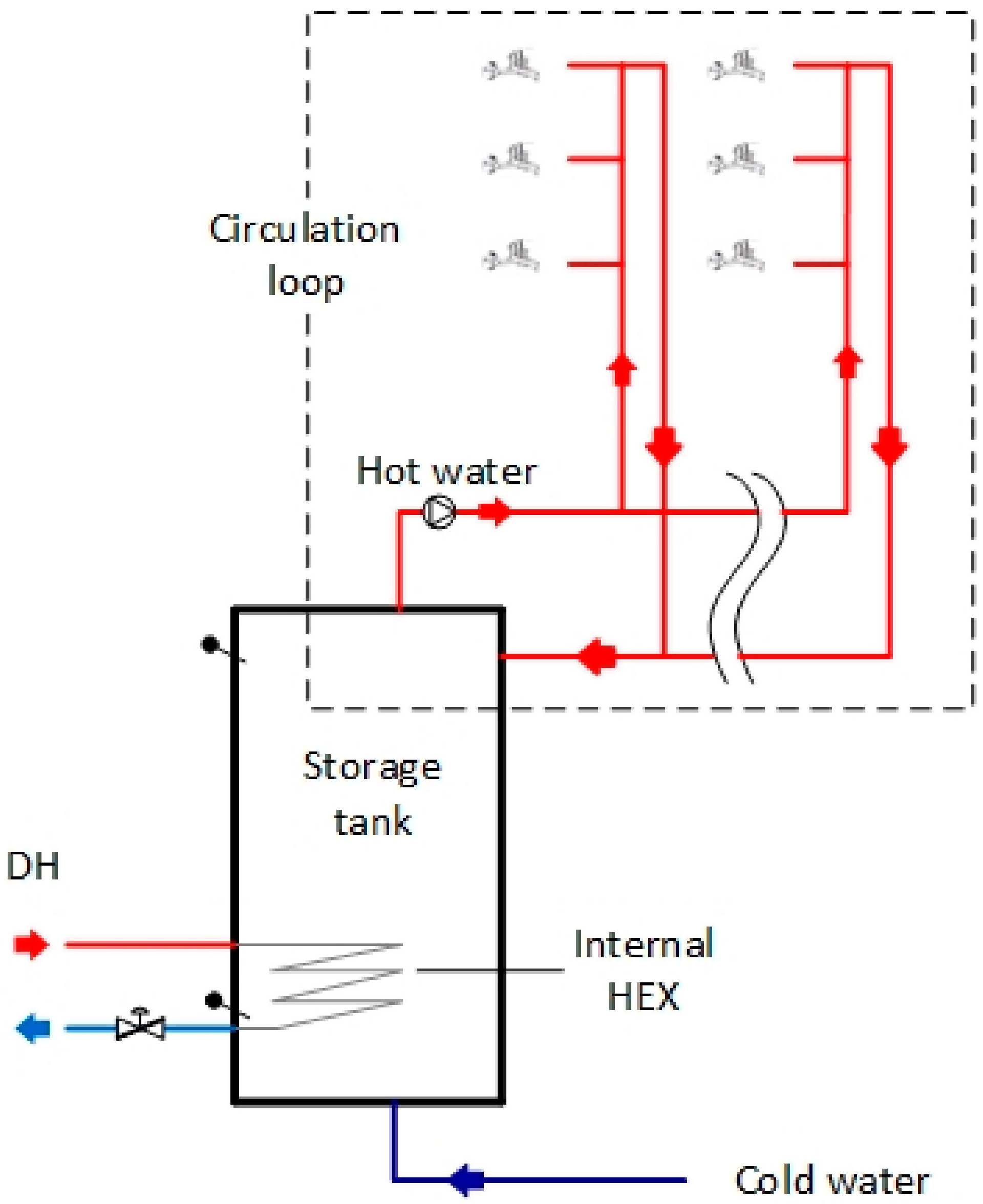
Abstract
:1. Introduction
1.1. Low-Temperature District Heating
1.2. Domestic Hot-Water Systems with Circulation
1.3. DHW Hygiene and Comfort Requirements
1.4. Problem Identification
1.4.1. Problems Regarding the DH Supply Temperature
1.4.2. Problems Regarding the DH Return Temperature
1.4.3. Circulation Heat Loss
1.5. Aim of the Study
1.6. State-of-the-Art
1.7. Novelty
2. Material and Methods
- DHW system with a storage tank with an internal heat exchanger;
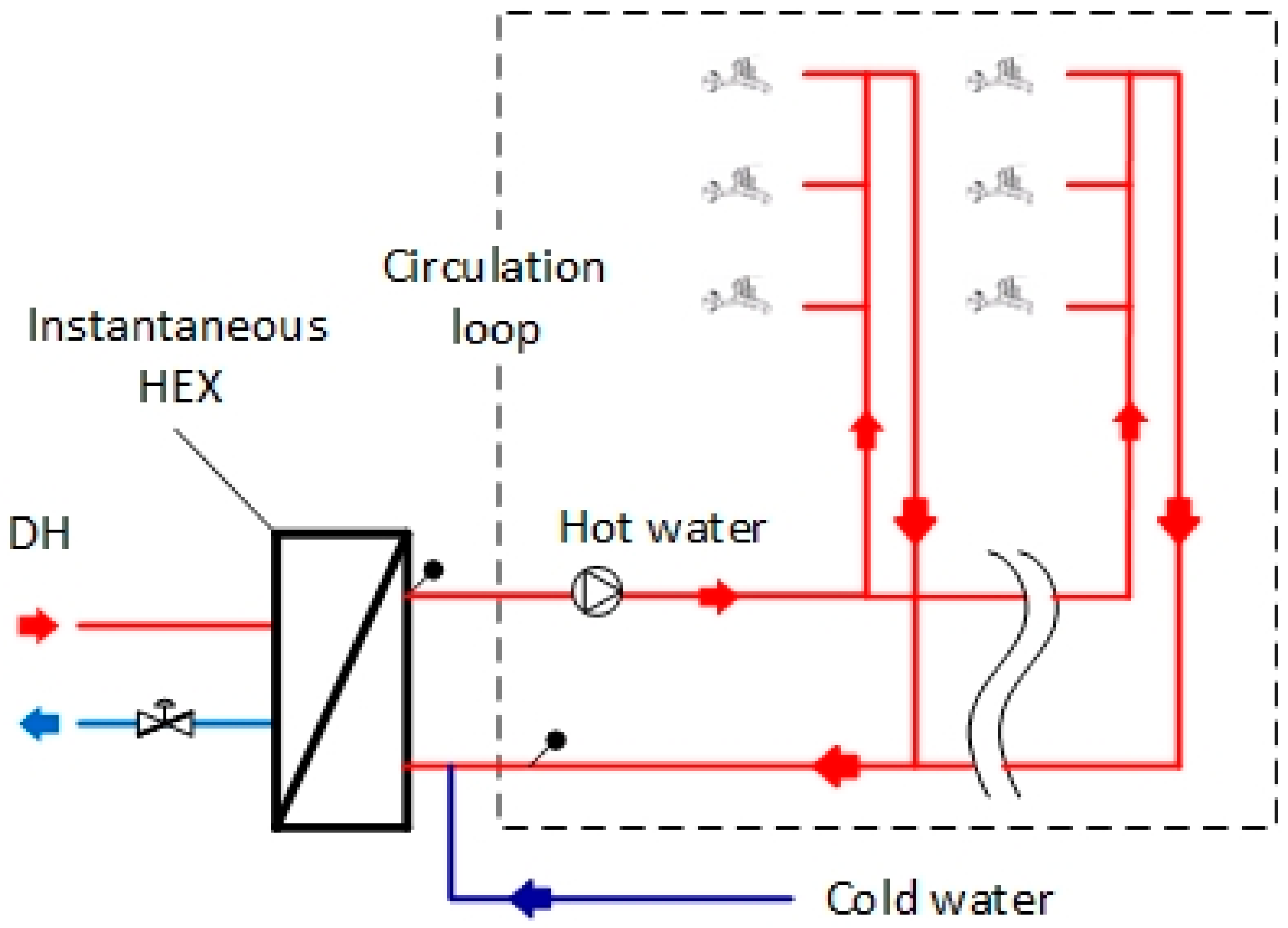
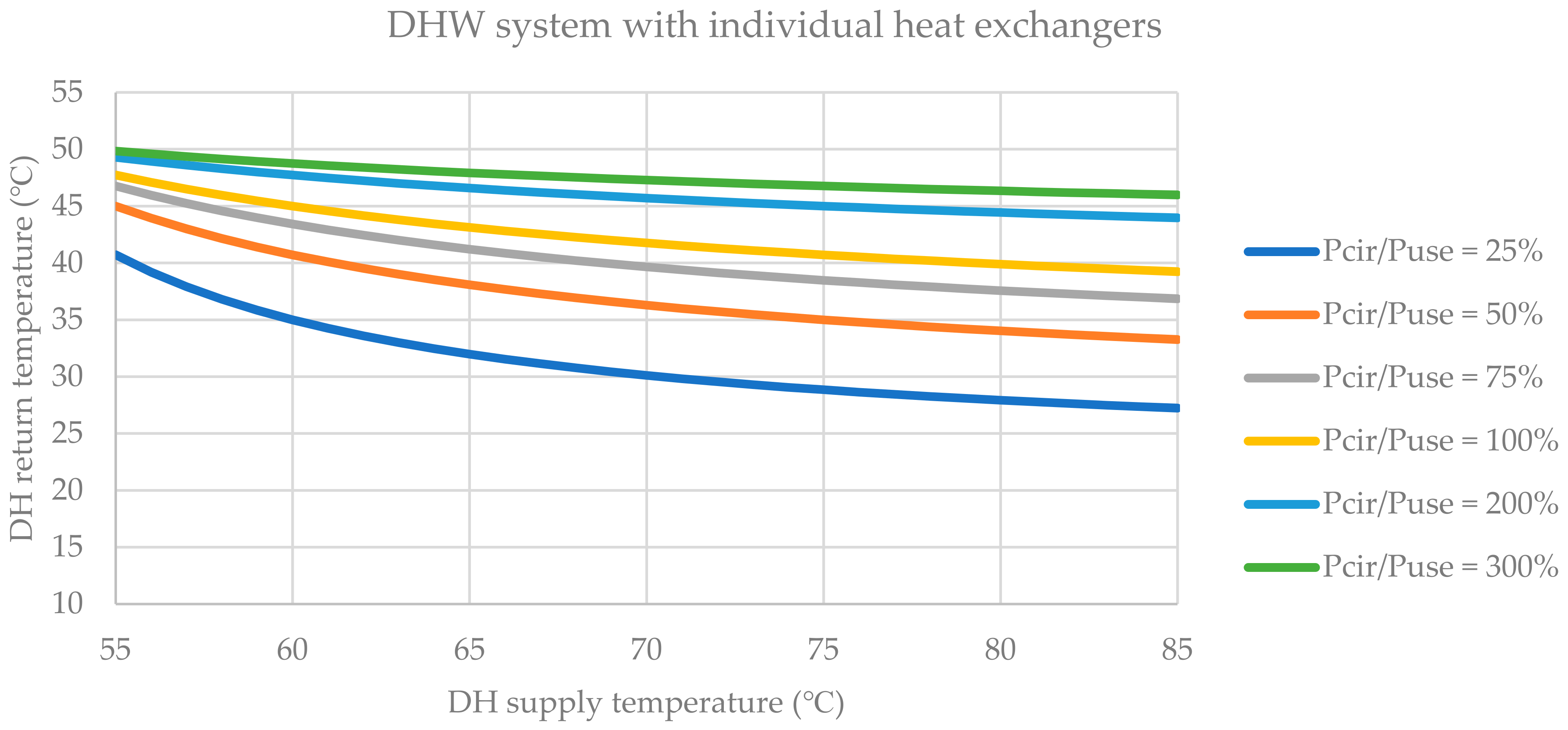
- DHW system with separate heat exchangers for hot water use and a hot-water circulation loop;
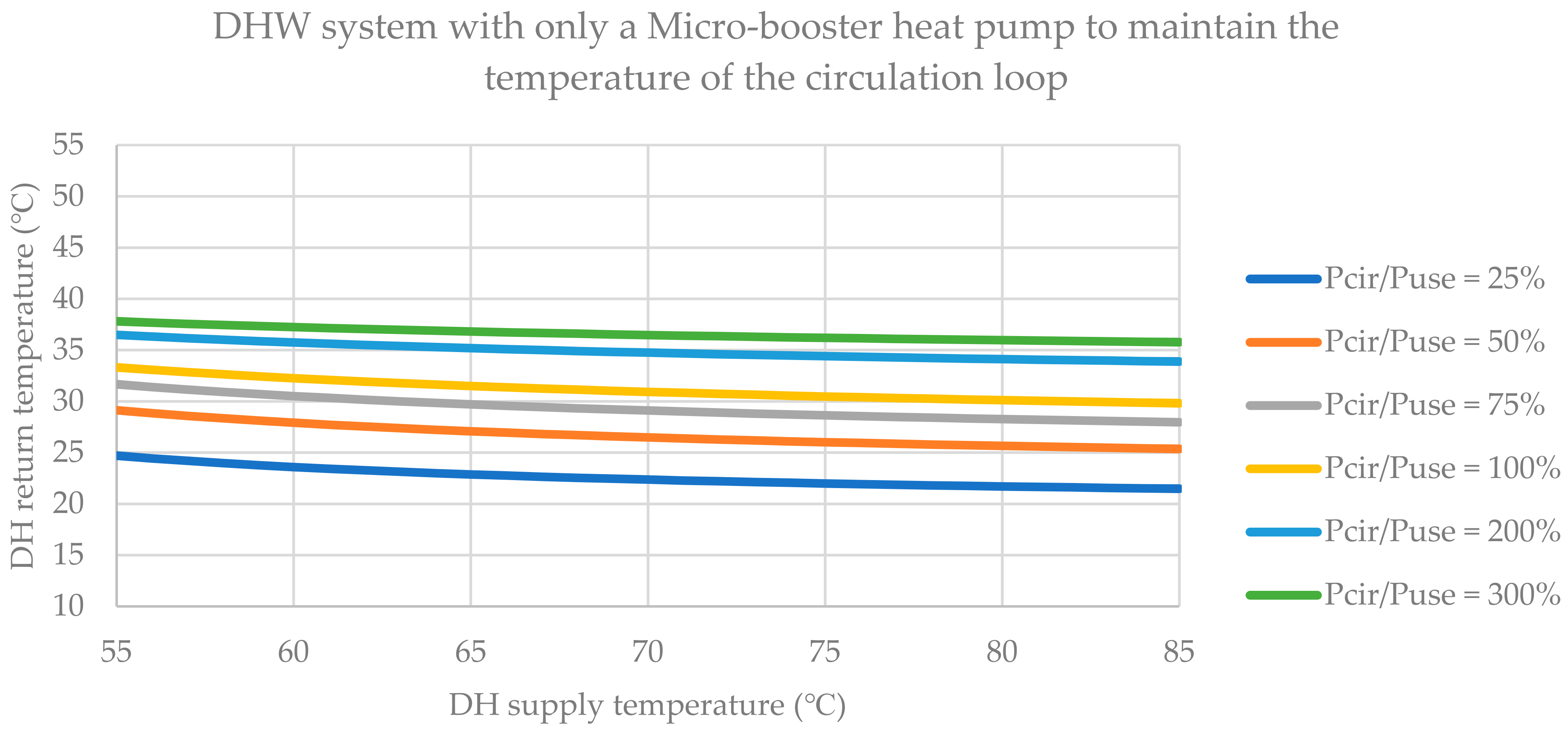
- DHW systems with micro-booster heat pumps to cool the return of district heating and heat the circulation loop;
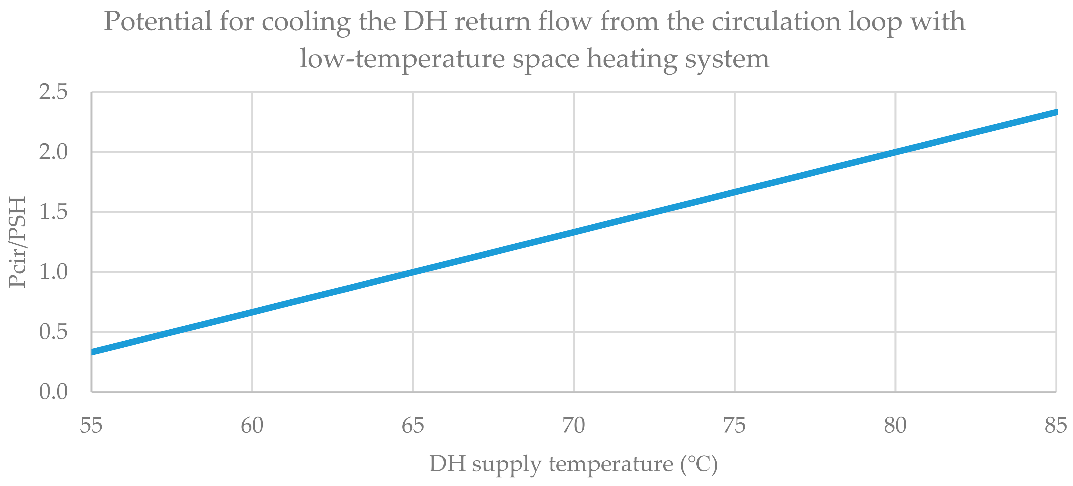
- The coupling of the district heating return flow from DHW systems to a space heating system with low return temperatures for the further cooling of the district heating return flow as an additional function compared to the previous systems.
2.1. Assumptions of Ideal Performance of Components
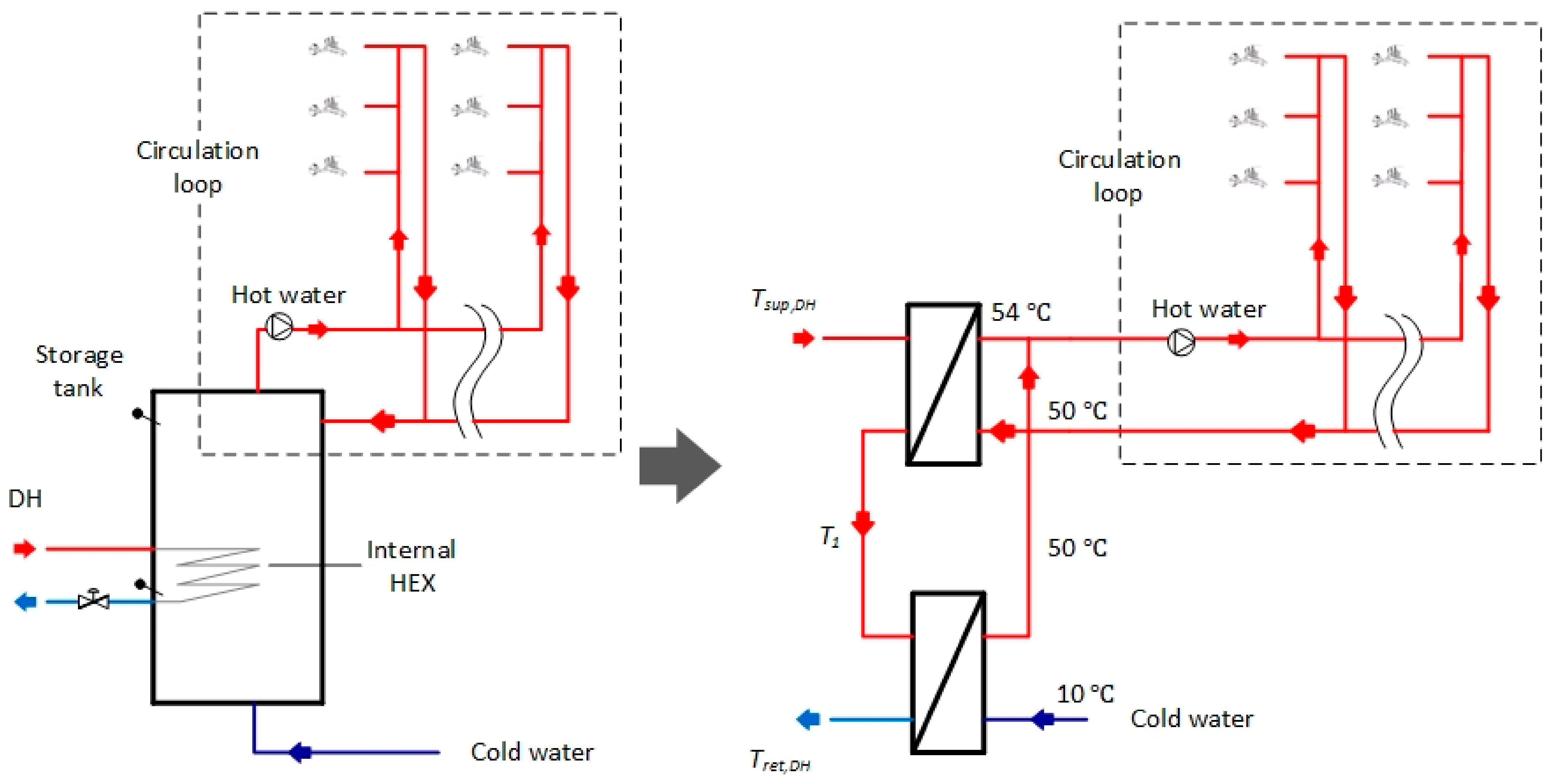
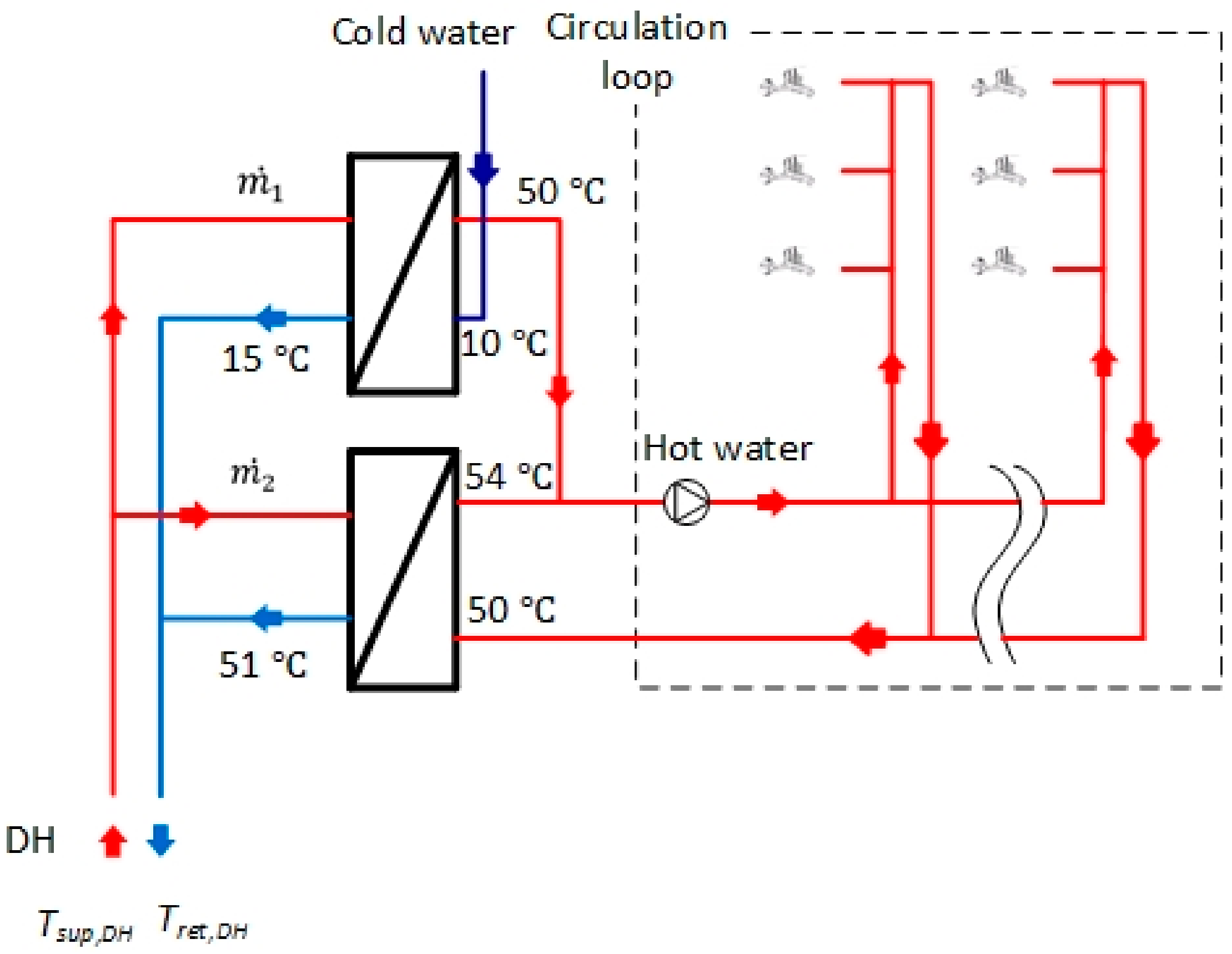
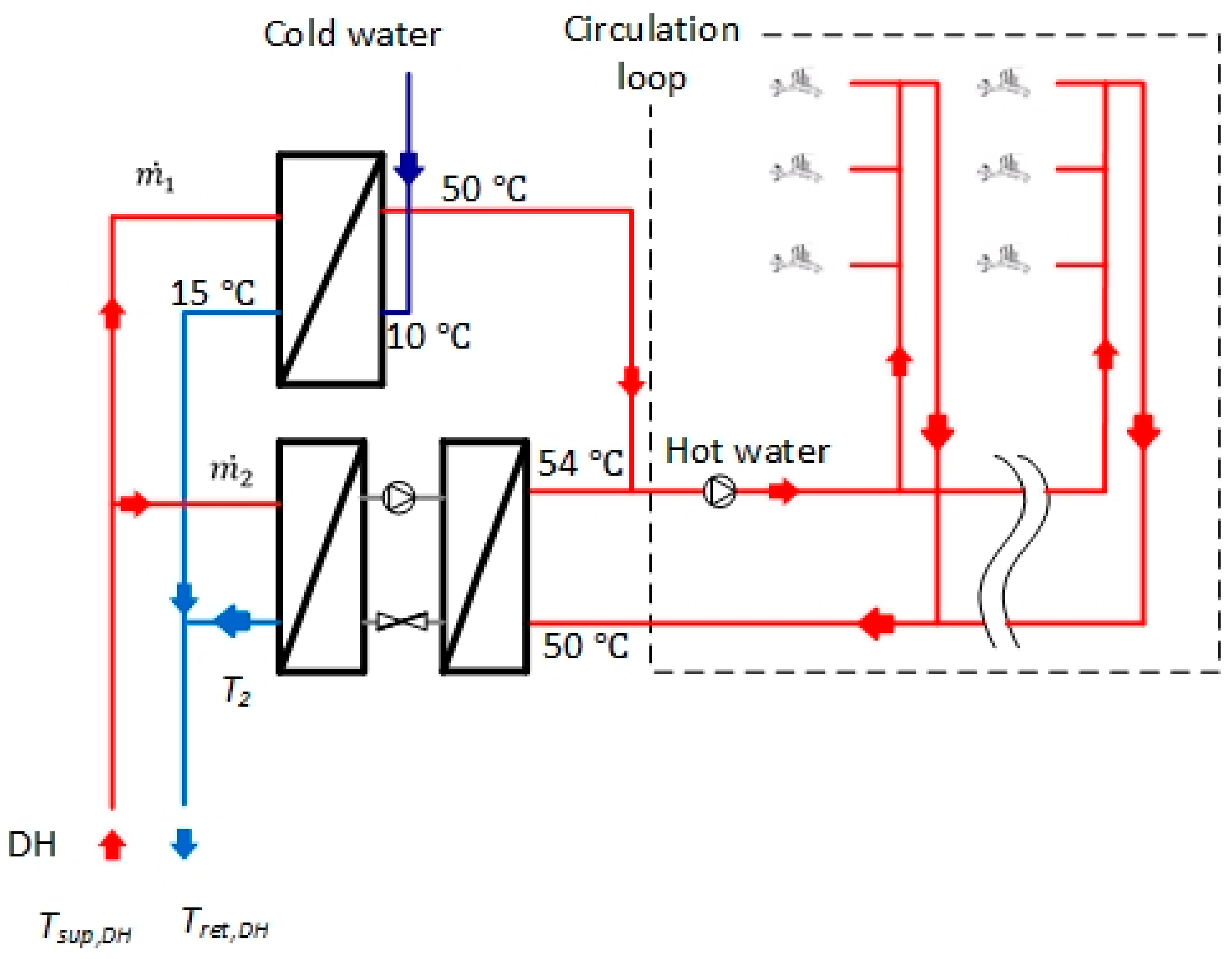
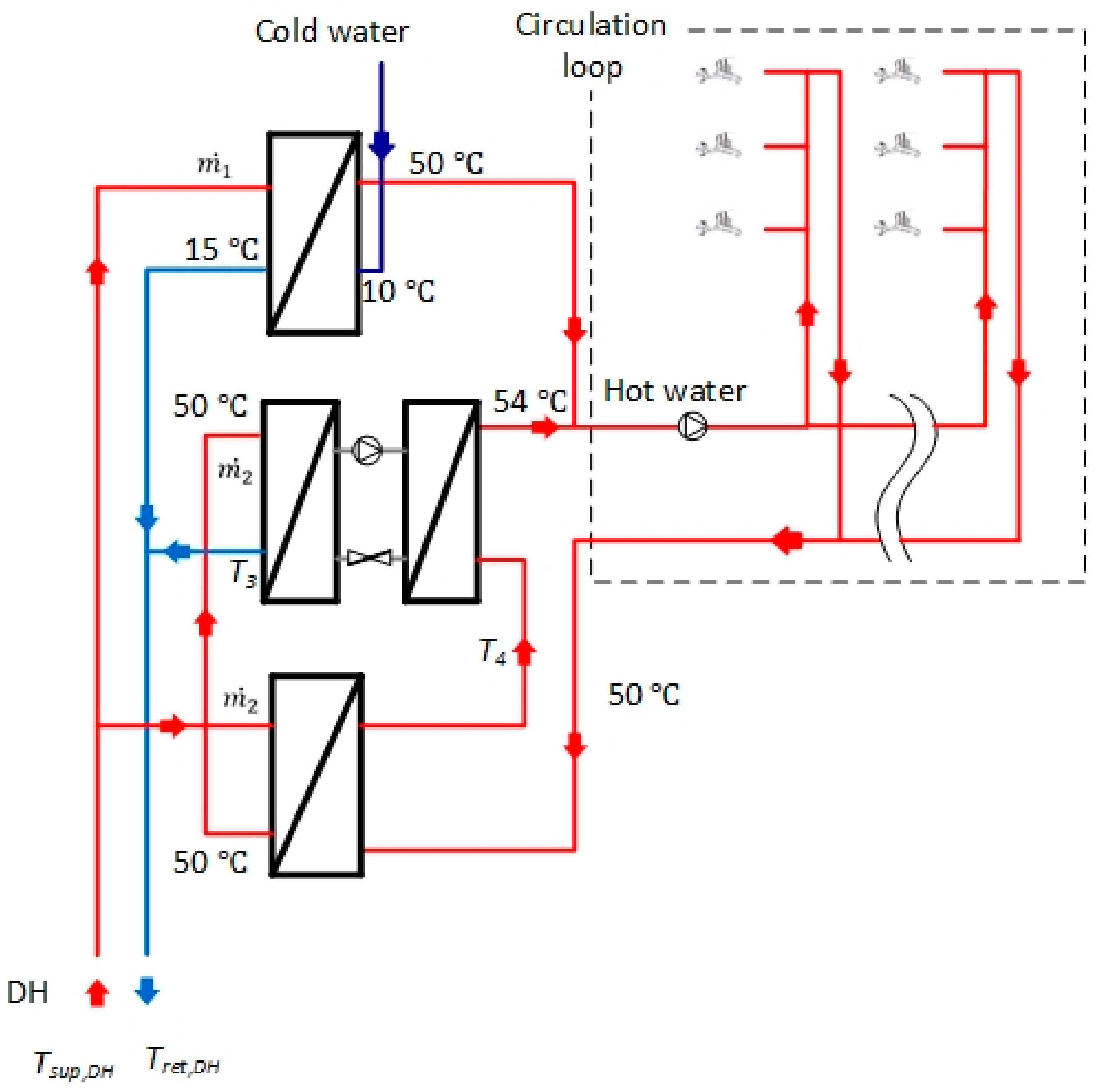
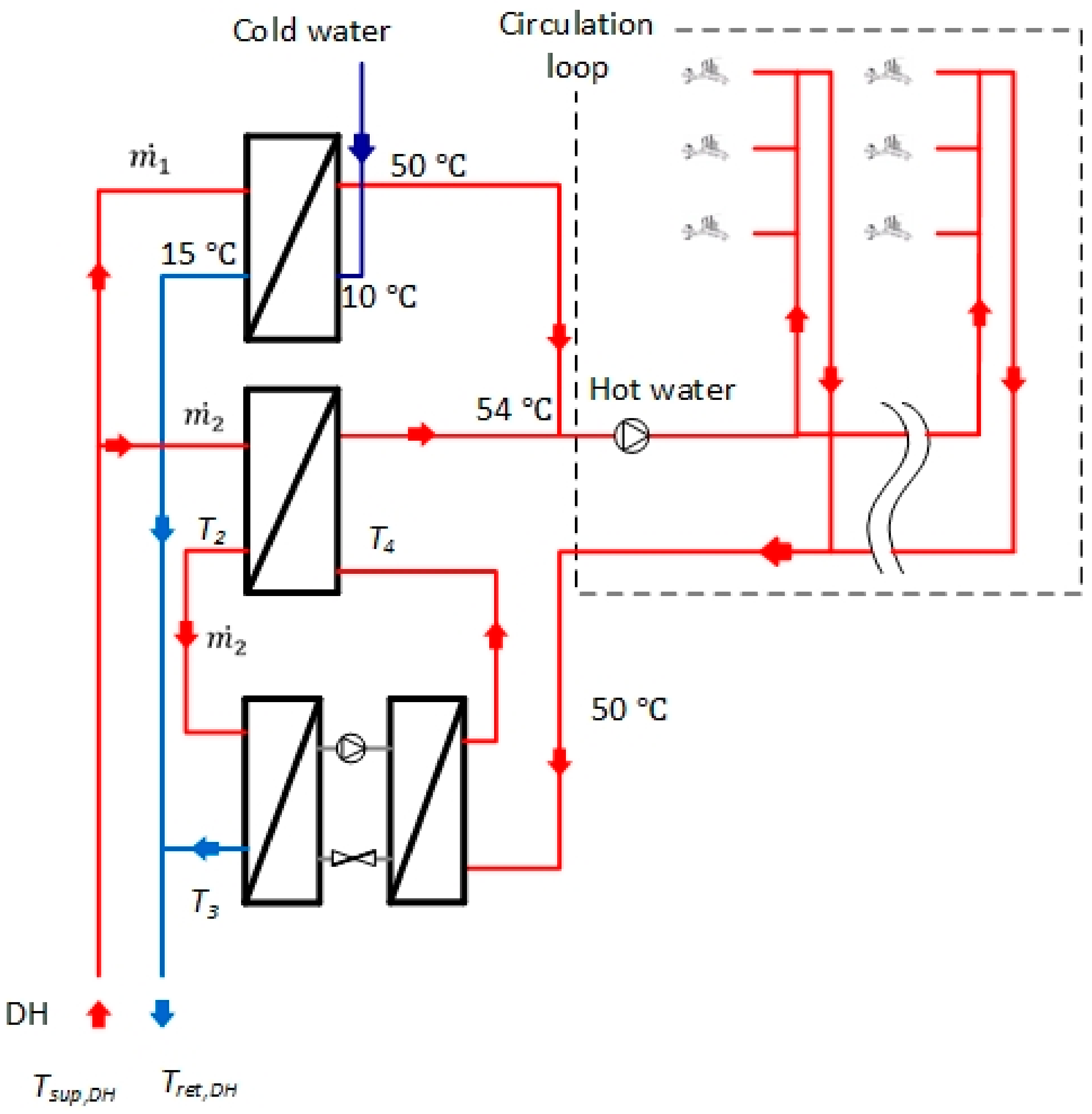
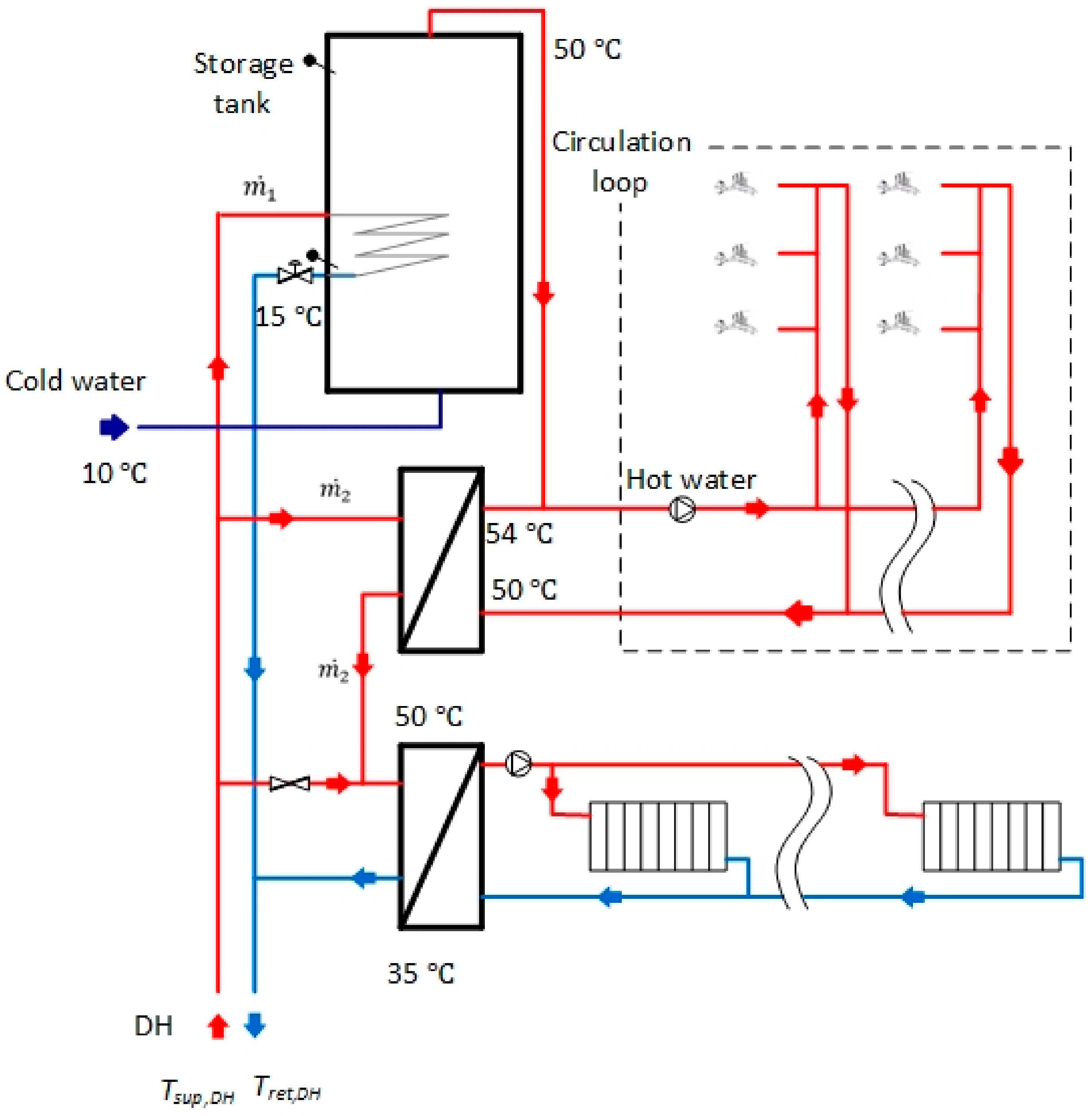
- The temperature of the hot water supplied to the circulation loop is 54 °C and the return temperature is 50 °C. This is in accordance with the Danish standards [19,20] and the recommendations by the Danish Technologic Institute [21] to prevent Legionella growth in the DHW system based on temperature sterilization;
- The operation of the DHW circulation loop is continuous and the circulation heat loss is the same each day. Again, according to the standards presented above, there must be a continuous circulation flow to secure thermal comfort;
- The DHW tank can be assumed to be big enough and be ideally stratified to supply the energy for heating DHW and for the circulation loop at a constant power equal to the daily average;
- The operation of the space heating system is in accordance with the LTDH requirements, with a return temperature of 30 °C from the secondary side;
- The temperature pinch between the primary outlet flow and the secondary inlet flow of the heat exchanger is assumed to be 1 °C for heat exchangers in the circulation loop.
2.2. DHW System with Storage Tank with Internal Heat exchanger
Capacity Limitation Functionality of the Storage Tank with Extra Safety Functionality
2.3. DHW System with Separate Heat Exchanger for Heating the Circulation Loop
2.4. DHW Systems with Micro-Booster Heat Pump for Hot-Water Circulation
2.4.1. DHW System with Micro-Booster Heat Pump
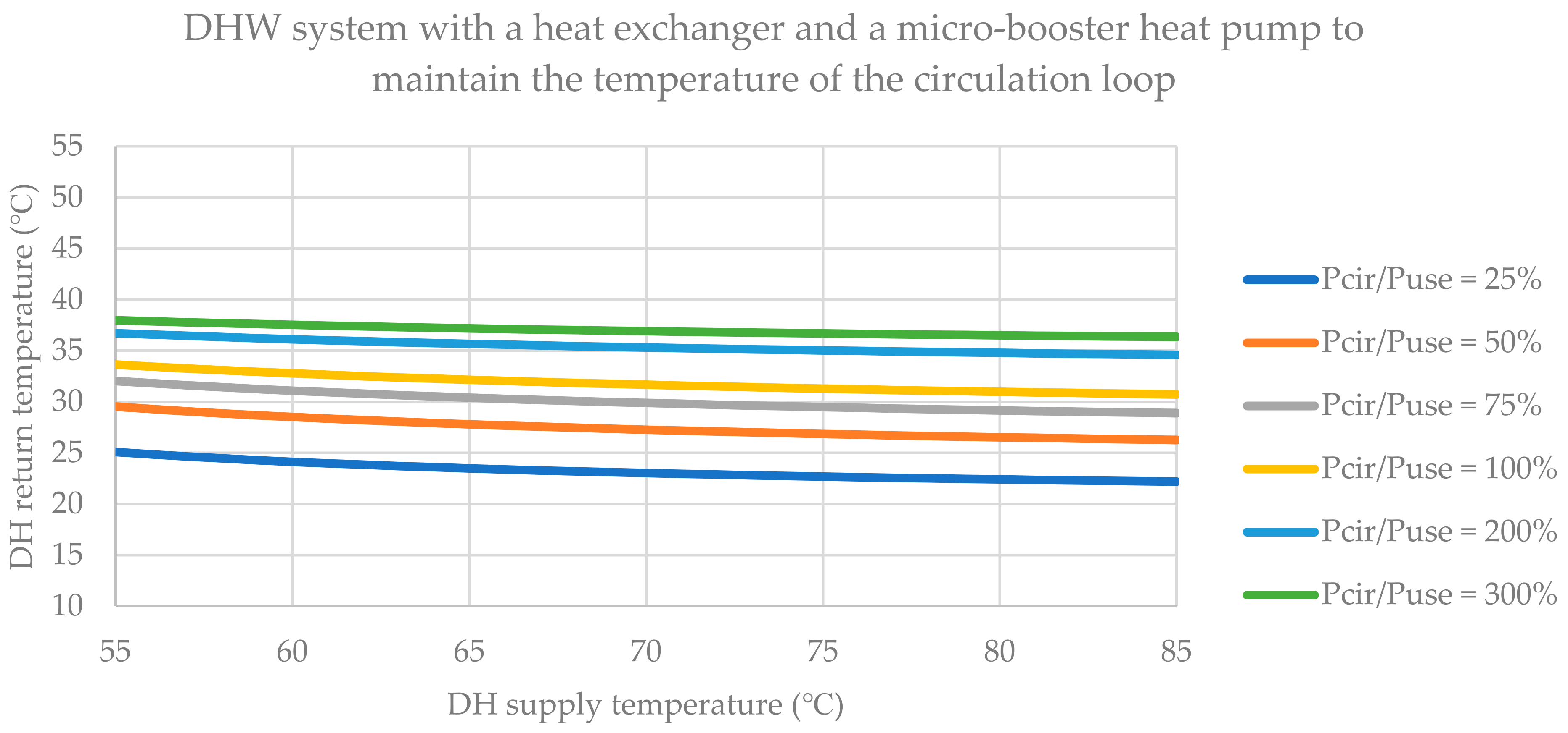
2.4.2. DHW System with a Heat Exchanger Before the Micro-Booster Heat Pump in the Circulation Loop
2.4.3. DHW System with a Secondary Heat Exchanger after the Micro-Booster Heat Pump in the Circulation Loop
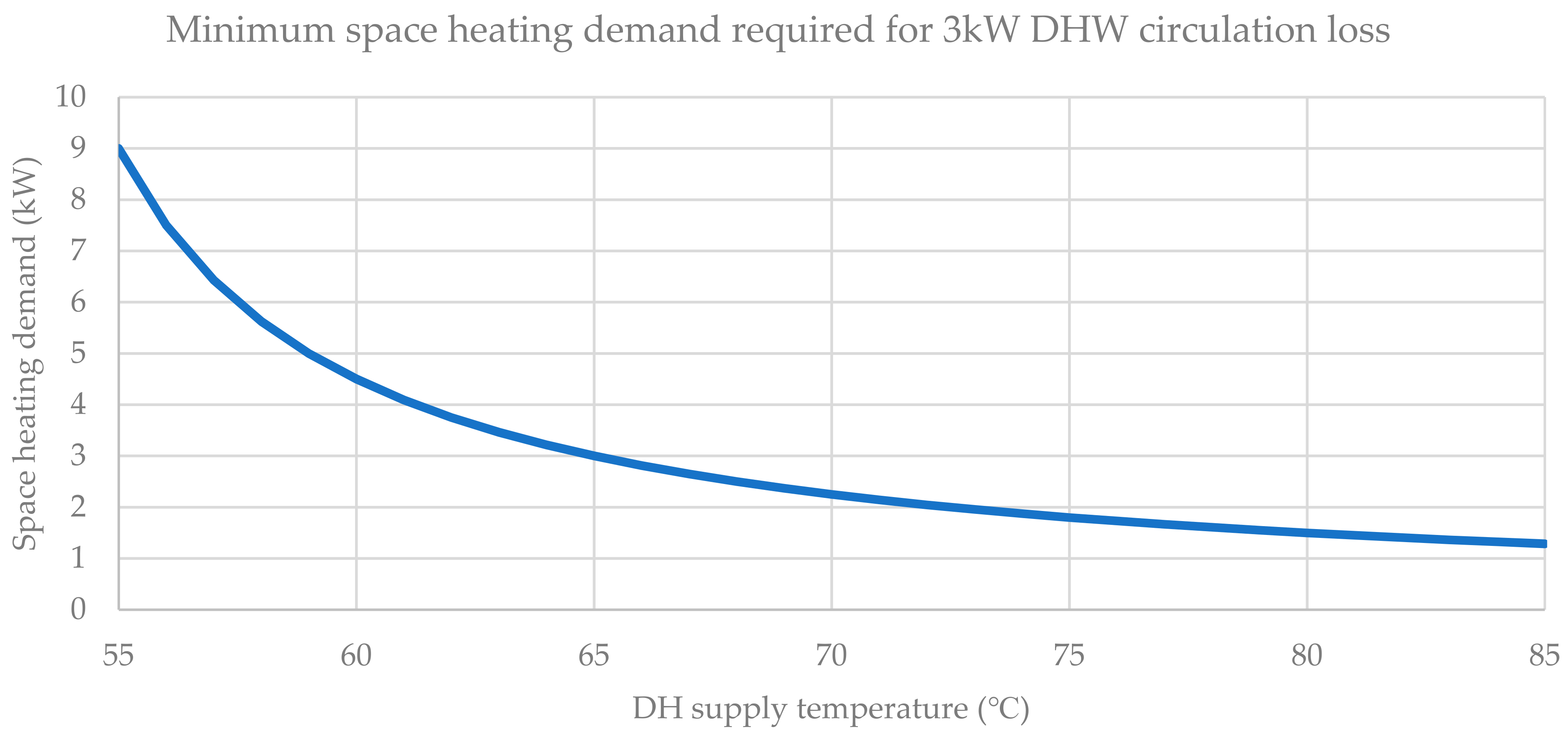
2.5. Combining the DHW System with a Low-Temperature Space Heating System
3. Results
3.1. DHW System with Storage Tank with Internal Heat Exchanger
Test Results of DHW Tank with a Heating Power Limitation Functionality and a Safety Function for Peak Loads
3.2. DHW System with Individual Heat Exchangers
3.3. DHW System with Micro-Booster Heat Pump
3.4. Combining the DHW System with Low-Temperature Space Heating System
4. Discussion
5. Conclusions
Author Contributions
Funding
Institutional Review Board Statement
Informed Consent Statement
Data Availability Statement
Acknowledgments
Conflicts of Interest
References
- European Commission. The European Green Deal. Eur. Comm. 2019, 53, 24. [Google Scholar] [CrossRef]
- European Commission. Going Climate-Neutral by 2050: A Strategic Long-Term Vision for a Prosperous, Modern, Competitive and Climate-Neutral EU Economy. Eur. Comm. 2019. [Google Scholar] [CrossRef]
- European Commission. A Clean Planet for All. A European Long-Term Strategic Vision for a Prosperous, Modern, Competitive and Climate Neutral Economy. Eur. Comm. 2018, 2018, 114. [Google Scholar]
- Connolly, D.; Lund, H.; Mathiesen, B.V.; Werner, S.; Möller, B.; Persson, U.; Boermans, T.; Trier, D.; Østergaard, P.A.; Nielsen, S. Heat Roadmap Europe: Combining District Heating with Heat Savings to Decarbonise the EU Energy System. Energy Policy 2014, 65, 475–489. [Google Scholar] [CrossRef]
- Lund, H.; Werner, S.; Wiltshire, R.; Svendsen, S.; Thorsen, J.E.; Hvelplund, F.; Mathiesen, B.V. 4th Generation District Heating (4GDH): Integrating Smart Thermal Grids into Future Sustainable Energy Systems. Energy 2014, 68, 1–11. [Google Scholar] [CrossRef]
- Benakopoulos, T.; Salenbien, R.; Vanhoudt, D.; Svendsen, S. Improved Control of Radiator Heating Systems with Thermostatic Radiator Valves without Pre-Setting Function. Energies 2019, 12, 3215. [Google Scholar] [CrossRef] [Green Version]
- Østergaard, D.S. Heating of Existing Buildings by Low-Temperature District Heating; Technical University of Denmark: Copenhagen, Denmark, 2018. [Google Scholar]
- Lund, H.; Østergaard, P.A.; Chang, M.; Werner, S.; Svendsen, S.; Sorknæs, P.; Thorsen, J.E.; Hvelplund, F.; Mortensen, B.O.G.; Mathiesen, B.V.; et al. The Status of 4th Generation District Heating: Research and Results. Energy 2018. [Google Scholar] [CrossRef]
- Østergaard, D.S.; Svendsen, S. Theoretical Overview of Heating Power and Necessary Heating Supply Temperatures in Typical Danish Single-Family Houses from the 1900s. Energy Build. 2016, 126, 375–383. [Google Scholar] [CrossRef] [Green Version]
- Østergaard, D.; Svendsen, S. Space Heating with Ultra-Low-Temperature District Heating-A Case Study of Four Single-Family Houses from the 1980s. Energy Procedia 2017, 116, 226–235. [Google Scholar] [CrossRef]
- Østergaard, D.S.; Svendsen, S. Replacing Critical Radiators to Increase the Potential to Use Low-Temperature District Heating —A Case Study of 4 Danish Single-Family Houses from the 1930s. Energy 2016, 110, 75–84. [Google Scholar] [CrossRef] [Green Version]
- Østergaard, D.S.; Svendsen, S. Are Typical Radiators Over-Dimensioned? An Analysis of Radiator Dimensions in 1645 Danish Houses. Energy Build. 2018, 178, 206–215. [Google Scholar] [CrossRef]
- Tunzi, M.; Østergaard, D.S.; Svendsen, S.; Boukhanouf, R.; Cooper, E. Method to Investigate and Plan the Application of Low Temperature District Heating to Existing Hydraulic Radiator Systems in Existing Buildings. Energy 2016, 113, 413–421. [Google Scholar] [CrossRef]
- Østergaard, D.S.; Svendsen, S. Experience from a Practical Test of Low-Temperature District Heating for Space Heating in Five Danish Single-Family Houses from the 1930s. Energy 2018, 159, 569–578. [Google Scholar] [CrossRef]
- Brand, M.; Svendsen, S. Renewable-Based Low-Temperature District Heating for Existing Buildings in Various Stages of Refurbishment. Energy 2013, 62, 311–319. [Google Scholar] [CrossRef]
- Bøhm, B.; Schrøder, F.; Bergsøe, N.C. Varmt Brugsvand: Måling Af Forbrug Og Varmetab Fra Cirkulationsledninger; SBI Forlag: Aalborg, Denmark, 2009. [Google Scholar]
- Bøhm, B. Production and Distribution of Domestic Hot Water in Selected Danish Apartment Buildings and Institutions. Analysis of Consumption, Energy Efficiency and the Significance for Energy Design Requirements of Buildings. Energy Convers. Manag. 2013, 67, 152–159. [Google Scholar] [CrossRef]
- Danfoss A/S. District Heating Application Handbook; Danfoss A/S—District Energy: Nordborg, Denmark, 2012; Available online: https://files.danfoss.com/download/Heating/Handbooks/Application-Handbook_sep14.pdf (accessed on 23 February 2021).
- Danish Standards. DS 439:2009-Norm for Vandinstallationer [Code of Practice for Domestic Water Supply]. (In Danish). 2009. Available online: https://webshop.ds.dk/en-gb/standard/ds-4392009?CurrencyCode=EUR (accessed on 23 February 2021).
- Danish Standards. DS 469:2013-Heating and Cooling Systems in Buildings. 2013. Available online: https://webshop.ds.dk/en-gb/standard/ds-4692013?CurrencyCode=EUR (accessed on 23 February 2021).
- Teknologisk Institut. Rørcenter-Anvisning 017-Legionella Installationsprincipper OG Bekæmpelsesmetoder; Teknologisk Institut: Taastrup, Denmark, 2019; ISBN 978-87-999802-7-7. [Google Scholar]
- Yang, X. Supply of Domestic Hot Water at Comfortable Temperatures by Low-Temperature District Heating without Risk of Legionella; Technical University of Denamrk: Copenhagen, Denmark, 2016. [Google Scholar]
- Pomianowski, M.Z.; Johra, H.; Marszal-Pomianowska, A.; Zhang, C. Sustainable and Energy-Efficient Domestic Hot Water Systems: A Review. Renew. Sustain. Energy Rev. 2020, 128, 109900. [Google Scholar] [CrossRef]
- Lidberg, T.; Olofsson, T.; Ödlund, L. Impact of Domestic Hot Water Systems on District Heating Temperatures. Energies 2019, 12, 4694. [Google Scholar] [CrossRef] [Green Version]
- HOFOR. Tekniske Bestemmelser for Fjernvarme, Varmt Vand. pp. 1–16. Available online: https://www.hofor.dk/wp-content/uploads/2015/12/Tekniske_bestemmelser_vand_endelig.pdf (accessed on 23 February 2021).
- Cholewa, T.; Siuta-Olcha, A.; Anasiewicz, R. On the Possibilities to Increase Energy Efficiency of Domestic Hot Water Preparation Systems in Existing Buildings—Long Term Field Research. J. Clean. Prod. 2019, 217, 194–203. [Google Scholar] [CrossRef]
- Köfinger, M.; Basciotti, D.; Schmidt, R.R.; Meissner, E.; Doczekal, C.; Giovannini, A. Low Temperature District Heating in Austria: Energetic, Ecologic and Economic Comparison of Four Case Studies. Energy 2016, 110, 95–104. [Google Scholar] [CrossRef]
- Brand, M.; Thorsen, J.E.; Svendsen, S.; Christiansen, C.H. A Direct Heat Exchanger Unit Used for Domestic Hot Water Supply in a Single-Family House Supplied by Low Energy District Heating. In Proceedings of the 12th International Symposium on District Heating and Cooling, Tallinn, Estonia, 5–7 September 2010. [Google Scholar]
- Minetto, S. Theoretical and Experimental Analysis of a CO2 Heat Pump for Domestic Hot Water. Int. J. Refrig. 2011, 34, 742–751. [Google Scholar] [CrossRef]
- Corberán, J.M.; Cazorla-Marín, A.; Marchante-Avellaneda, J.; Montagud, C. Dual Source Heat Pump, a High Efficiency and Cost-Effective Alternative for Heating, Cooling and DHW Production. Int. J. Low-Carbon Technol. 2018, 13, 161–176. [Google Scholar] [CrossRef]
- Niemelä, T.; Manner, M.; Laitinen, A.; Sivula, T.M.; Jokisalo, J.; Kosonen, R. Computational and Experimental Performance Analysis of a Novel Method for Heating of Domestic Hot Water with a Ground Source Heat Pump System. Energy Build. 2018, 161, 22–40. [Google Scholar] [CrossRef] [Green Version]
- Huang, T.; Yang, X.; Svendsen, S. Multi-Mode Control Method for the Existing Domestic Hot Water Storage Tanks with District Heating Supply. Energy 2020, 191, 116517. [Google Scholar] [CrossRef]
- Yang, X.; Svendsen, S. Improving the District Heating Operation by Innovative Layout and Control Strategy of the Hot Water Storage Tank. Energy Build. 2020, 224, 110273. [Google Scholar] [CrossRef]
- Yang, X.; Kristian, H. Installation and Demonstration of Capacity Limitation Functionality for Domestic Hot Water Tank in a New Building to Reduce Peak Load, Lower Return Temperature and Utilize Thermal Flexibility in Domestic Hot Water Tanks Deliverable No D5. 4c (I). 2019. Available online: http://www.energylabnordhavn.com/uploads/3/9/5/5/39555879/d5.4c_i__optimum_dhw_new_building.pdf (accessed on 23 February 2021).
- Thorsen, J.E.; Skov, M.; Honoré, K. Installation and Demonstration of Domestic Hot Water Circulation Booster for Reducing District Heating Return Temperature Deliverable No: D5 4b. 2019. Available online: http://www.energylabnordhavn.com/uploads/3/9/5/5/39555879/d5.4b_dhw_circulation_booster.pdf (accessed on 23 February 2021).
- DANFOSS REDAN A/S. AKVA LUX II. Available online: https://assets.website-files.com/5aeab7326e89985e5822ad30/5f61bad04dc6bf37774c2836_1758557.pdf (accessed on 23 February 2021).
- METRO THERM. Liquid-to-Water Domestic hot Water Heat Pump for Single-Family Houses. Available online: https://www.metrotherm.dk/en/products/heat-pumps/domestic-hot-water-heat-pumps/metro-microbooster (accessed on 23 February 2021).


Publisher’s Note: MDPI stays neutral with regard to jurisdictional claims in published maps and institutional affiliations. |
© 2021 by the authors. Licensee MDPI, Basel, Switzerland. This article is an open access article distributed under the terms and conditions of the Creative Commons Attribution (CC BY) license (https://creativecommons.org/licenses/by/4.0/).
Share and Cite
Benakopoulos, T.; Vergo, W.; Tunzi, M.; Salenbien, R.; Svendsen, S. Overview of Solutions for the Low-Temperature Operation of Domestic Hot-Water Systems with a Circulation Loop. Energies 2021, 14, 3350. https://0-doi-org.brum.beds.ac.uk/10.3390/en14113350
Benakopoulos T, Vergo W, Tunzi M, Salenbien R, Svendsen S. Overview of Solutions for the Low-Temperature Operation of Domestic Hot-Water Systems with a Circulation Loop. Energies. 2021; 14(11):3350. https://0-doi-org.brum.beds.ac.uk/10.3390/en14113350
Chicago/Turabian StyleBenakopoulos, Theofanis, William Vergo, Michele Tunzi, Robbe Salenbien, and Svend Svendsen. 2021. "Overview of Solutions for the Low-Temperature Operation of Domestic Hot-Water Systems with a Circulation Loop" Energies 14, no. 11: 3350. https://0-doi-org.brum.beds.ac.uk/10.3390/en14113350