
Application of the Deep CNN-Based Method in Industrial System for Wire Marking Identification

 ,
,  ,
,
Abstract
:1. Introduction
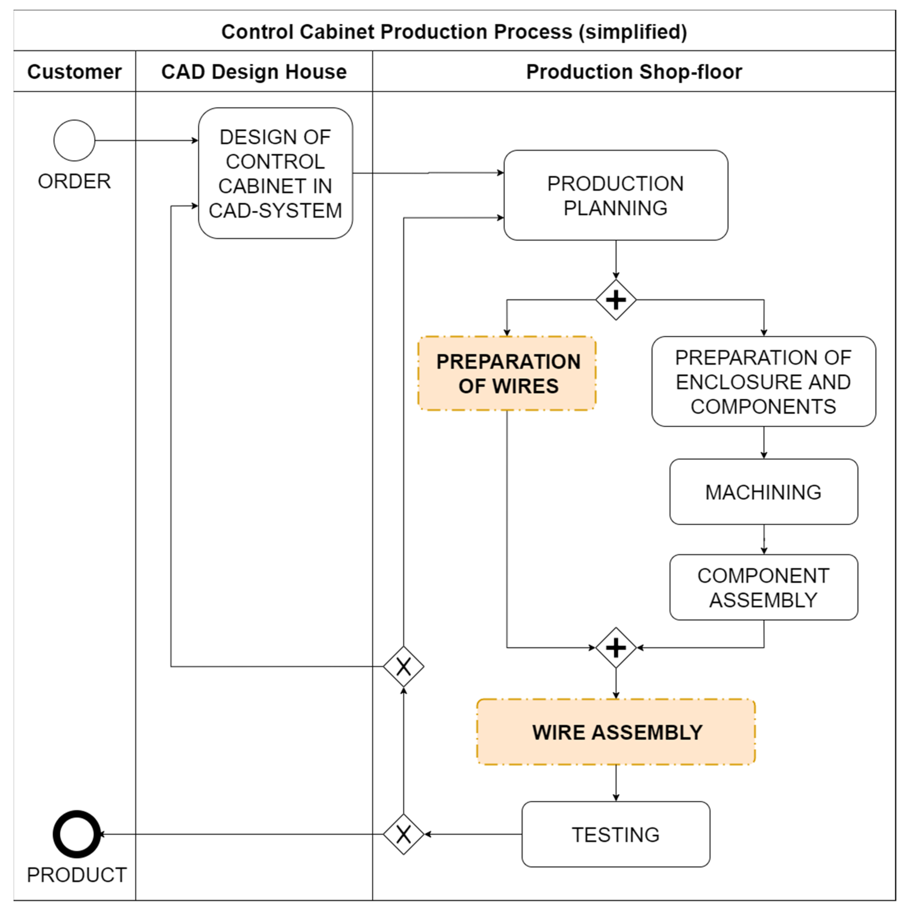
1.1. Shaping the Solutions for Wire Assembly Process of the Control Cabinets
1.2. Wire Marking Identification with Deep Neural Network Applications
1.3. Challenges of Wire Marking Identification
2. Literature Review
- Sequence recognition methods [65];
3. Materials and Methods
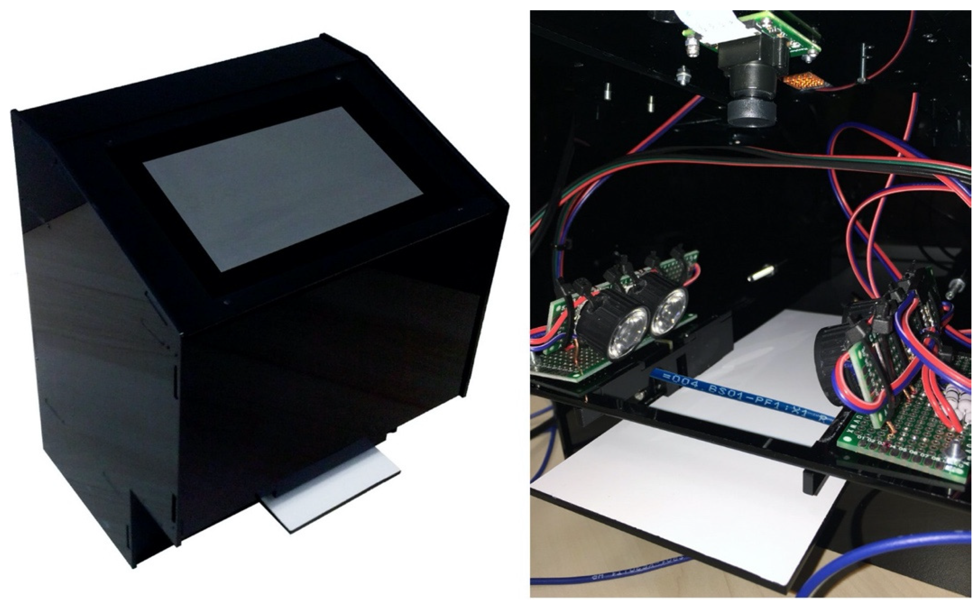
3.1. The Device for Identifying Wire Markings
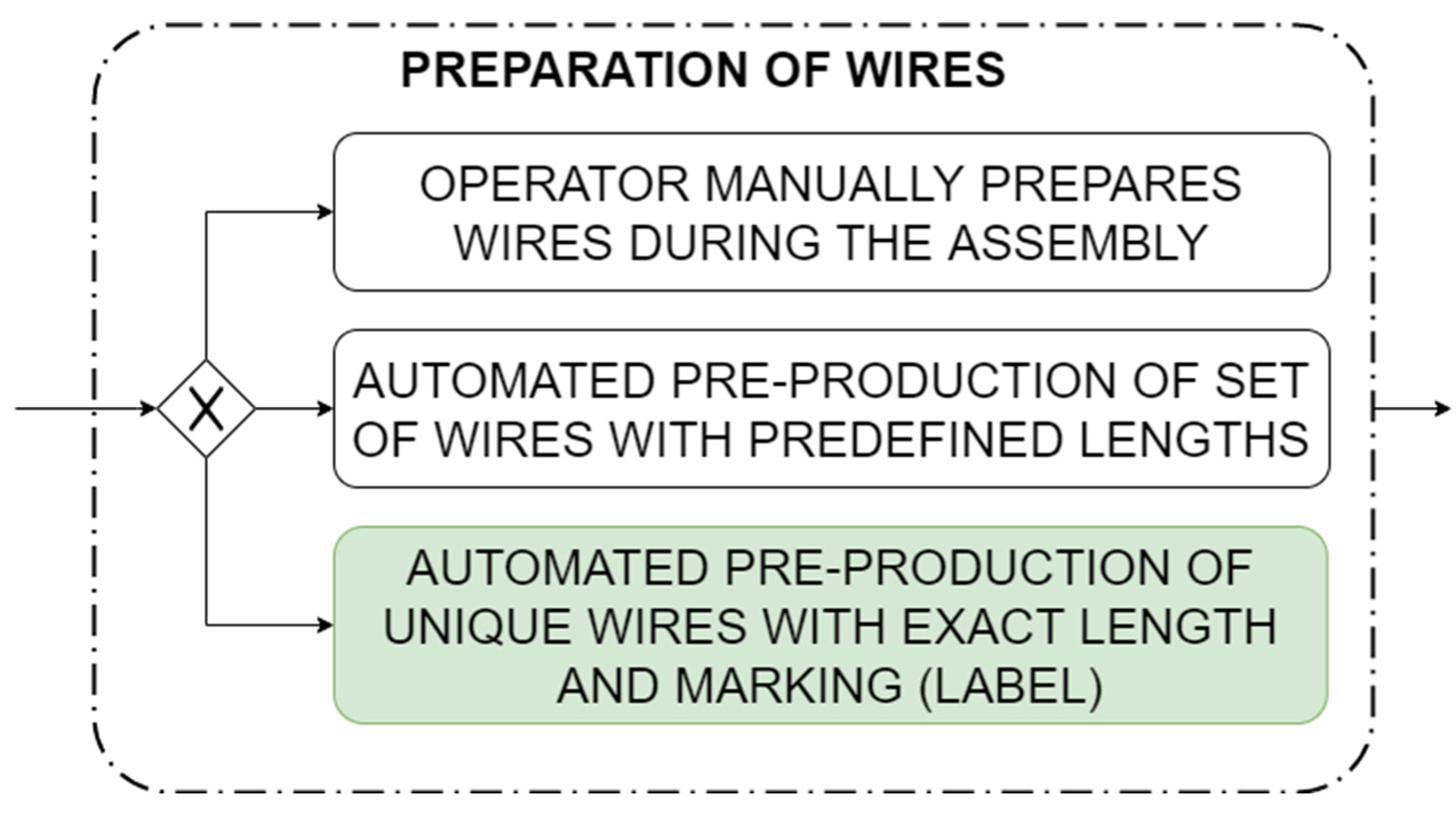
3.1.1. Preparation of the Wires
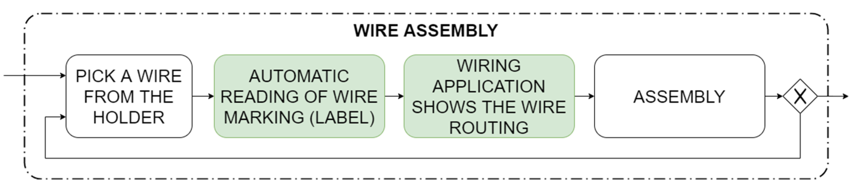
3.1.2. Wires Assembly
- Select a wire to be assembled (typing the wire label or automatic reading by the reading prototype); the ESW displays the needed assembly information; the assembling employee considers the information and interprets the entire wiring 3D visualization in order to learn the appropriate routing;
- Enlarge the visualization by zooming into the graphics in order to recognize the first connection point of the wire end;
- Reduce the visualization in order to check the wiring route through the wire ducts;
- Enlarge the visualization by zooming into the graphics in order to recognize the second connection point of the wire end.
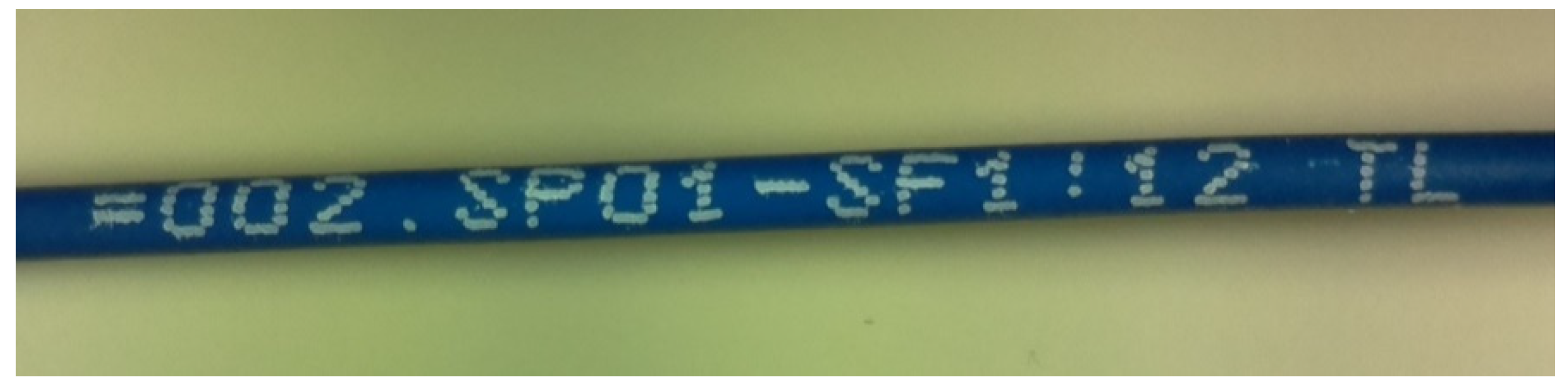
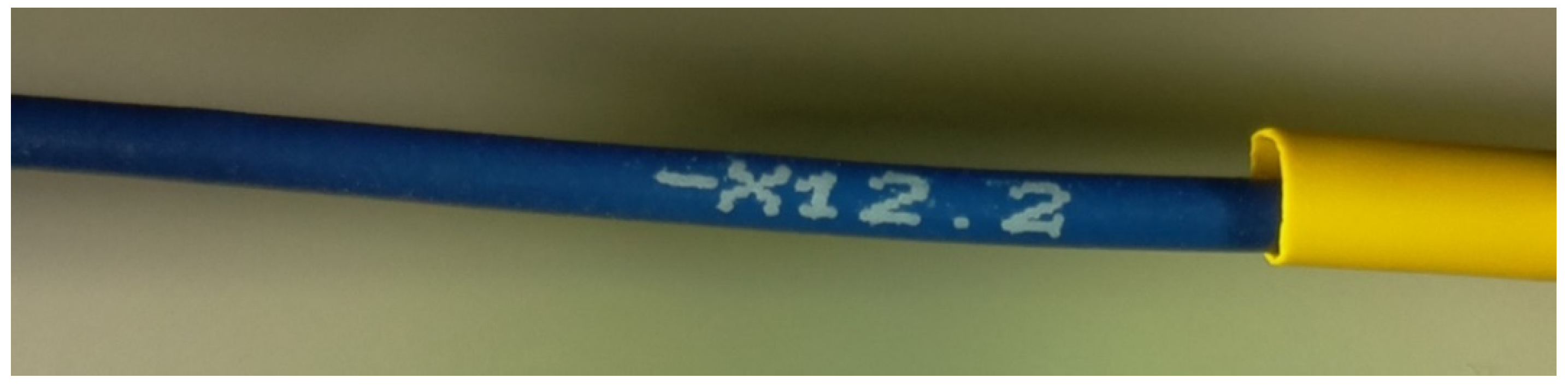
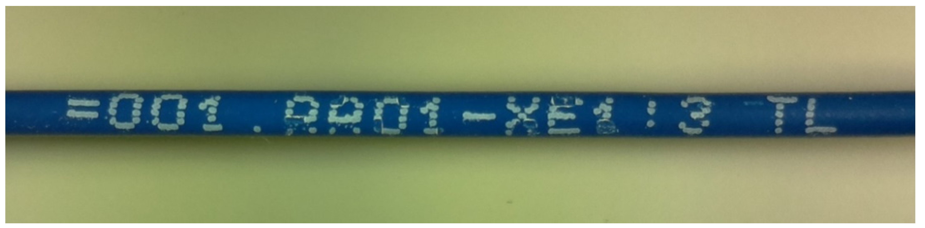
- Recognition of the font, as readable and as clear as possible;
- Recognition of all the printed characters, including those printed faultily;
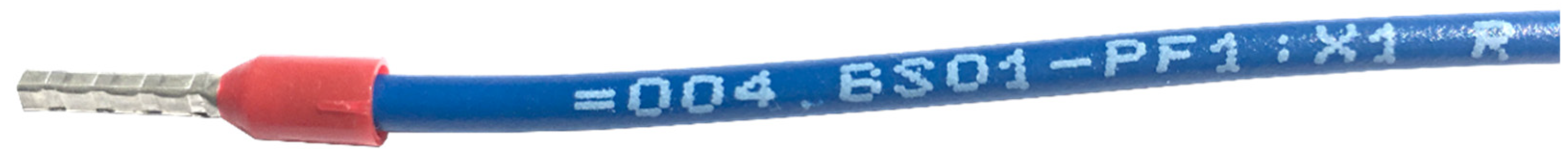
- Identification of wires of 1.5 mm2 cross section, covered with blue insulation and the marking printed in a white font;
- Complex integration at the system level with the ESW wiring assembly support software system.
3.2. Challenges of Wire Image Recognition
3.3. The Method for Identifying Wire Markings
3.3.1. The Reading Process for Wire Markings and the Method Applied
- Input layer characterized and noted as (32 × 32 × 3), which stands for sizes of elementary image 32 by 32 pixels, namely, (image height) × (image width) and three fundamental colors (the RGB image processing scale is applied);
- The first convolutional layer is equipped with 32 filters of 3 × 3 pixels input size;
- The first maximum pooling layer is sized as 2 × 2 pixels;
- The second convolutional layer is equipped with 32 filters of 3 × 3 pixels input size;
- The second maximum pooling layer is sized as 2 × 2 pixels;
- A dense layer of 128 nodes;
- An output layer is differentiated for each DCNN: in the network allocated to search empty spaces between characters it is characterized by two nodes, namely, the empty space between the characters and a particular character, whereas in the case of the network allocated for the recognition of characters, it consists of the number of nodes equal to the number of characters used for wire markings, which certainly is a configurable parameter;
- All activating functions in both DCNNs are of the rectified linear unit ReLU type.
- Human description of the markings on the training images;
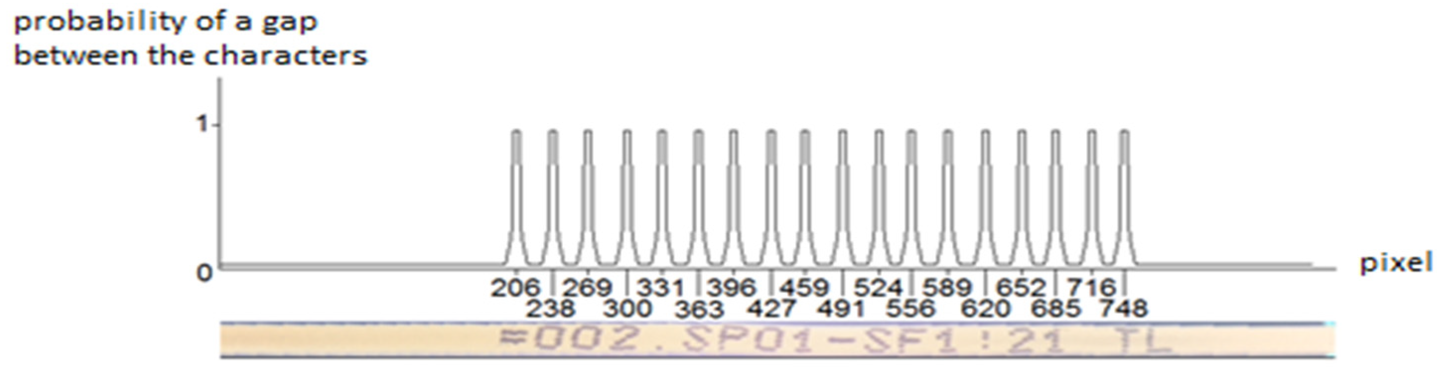
- Training the neural network in order to recognize empty spaces between the characters;
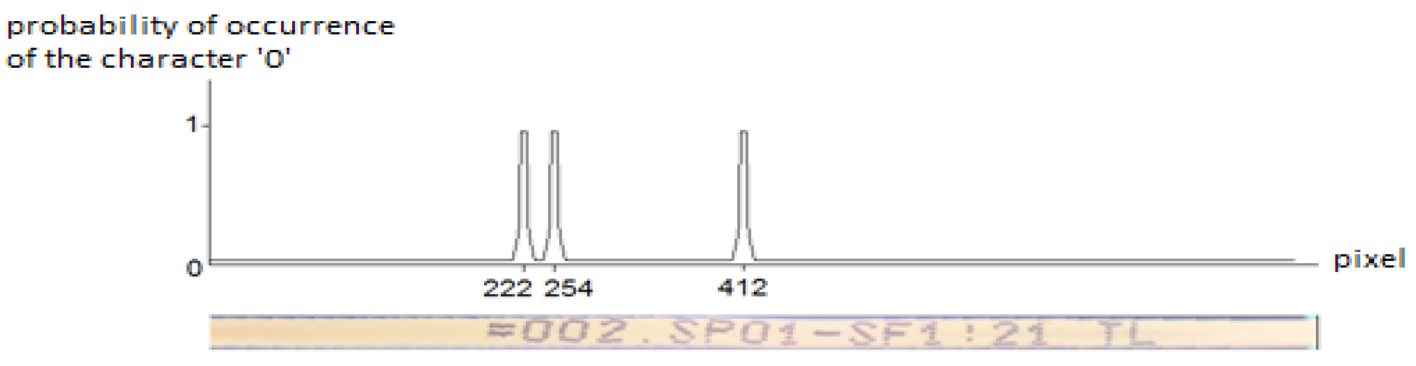
- Training a neural network in order to recognize particular characters.
4. Results of Neural Network Training; Application of the Prototype Device in the Wire Assembly Process and Users’ Opinions
4.1. Results of Neural Network Training
4.2. Tests of the Duration of the Assembly Process for Control Cabinets
- Look at an industrial enclosure: a glance, which takes 0.00600 min according to [79];
- Click the ESW assembly support system: click, which takes 5 TMU = 0.00300 min according to [100];
- The ESW system opening of the extended information with the 3D graphics of a selected wire on a wiring list: a value given in Table 1 was assumed;
- Look at the displayed wire length: a look at a single word takes 5.05 TMU according to [78], whereby the average number of such words is assumed to be three numerical characters printed on a wire per word (the number of characters is borrowed from the B-type process: 3/3 + 13/3 + 20/3 + 28/3 = 21.3 words); additionally, finger swiping on the wire while reading the words is also included as a convenience often used by employees reading a wire marking (2 TMU per a word according to [78]);
- Detach a wire with the closest predefined length from the holder: a look at the holder takes 0.00600 min according to [79], a straight grip of a wire takes 10.8 TMU according to [78], a reach of a distance of 30 cm (horizontal move of hand to choose a wire) to a holder takes 16.7 TMU according to [78], a reach a distance of 50 cm above holder with a wire in hand to get out a wire takes 10.8 TMU according to [78], and a move between wire strands takes 5.6 TMU according to [78];
- Look at the ESW assembly support system to identify the wire routing: reading a route by eye tracking at two wire’s ends and its middle (one such a basic activity takes 0.118000 min according to [79];
- Mount the wire: a look at an industrial enclosure takes 0.00600 min according to [79], a move of a wire at a distance of 30 cm takes 25.8 TMU according to [78], a move of a wire takes 12.9 TMU according to [78], an installation of one wire’s end (releasing of a grasp takes 0.00300 min according to [79]), the next look at an industrial enclosure, the next move of a wire, and the installation of second wire’s end occur;
- Hide a wire surplus in a wiring duct: precise allocation of a wire into wires duct (six actions were assumed: insertion at two wire’s ends and twice in a middle, including two corrections between a middle and an end; each action takes 0.015000 min according to [79]), two moves of a wire between its middle and an end, which take 15.2 TMU according to [78], four plugs of a wire into a wires’ duct (at two wire’s ends and twice in a middle), which takes 5.6 TMU each according to [78].
- Look at the industrial enclosure: a glance takes 0.00600 min according to [79];
- Detach the wire from the holder: a look at the holder takes 0.00600 min according to [79], a straight grip of a wire takes 10.8 TMU according to [78], a reach a distance of 50 cm above holder with a wire in hand to get out a wire takes 10.8 TMU according to [78], a move between wire strands takes 5.6 TMU according to [78];
- Grab a wire with both hands: a grip of a wire takes 10.8 TMU according to [78];
- Rotate a wire so that a label is visible with eyes: rotation of a wire takes 10.8 TMU according to [78];
- Type the label into the search window of the ESW assembly support system: a glance at a wire takes 0.00600 min according to [79], a glance at a keyboard takes 0.00600 min according to [80], a glance at ESW system’s monitor takes 0.00600 min according to [79], a click takes 5 TMU according to [100]; additionally, a finger swiping on a wire while reading the characters is also included as a convenience often used by employees reading a wire marking (2 TMU per three characters according to [79]);
- Click the result so that the extended information with the 3D graphics opens on the wiring list: a click takes 5 TMU according to [100];
- Look at the ESW assembly support system to identify a wire routing: a look at a single notation takes 5.05 TMU according to [78];
- Mount a wire: a look at an industrial enclosure takes 0.00600 min according to [79], a move of a wire at a distance of 30 cm takes 25.8 TMU according to [79], followed by an installation of one wire’s end (releasing of a grasp takes 0.00300 min according to [79]), the next look at an industrial enclosure, the next move of a wire, and an installation of second wire’s end.
- Look at an industrial enclosure: a glance takes 0.00600 min according to [79];
- Detach a wire from the holder: a look at the holder takes 0.00600 min according to [79]; a straight grip of a wire takes 10.8 TMU according to [78]; a reach of a distance of 50 cm above the holder with a wire in hand to get out a wire takes 10.8 TMU according to [78]; a move between wire strands takes 5.6 TMU according to [78];
- Grab a wire with both hands: a grip of a wire takes 10.8 TMU according to [78];
- Rotate the wire so that a label is visible with eyes: rotation of a wire takes 10.8 TMU according to [78];
- Move a wire with both hands towards the WLR: precise, symmetrical positioning, which is assumed as 10.8 TMU according to [80];
- Place a wire on the white background of the WLR: a move of a wire at a distance of 5 cm takes 5.2 TMU according to [78];
- Wait for the acoustic signal that the picture for recognition was taken: this is assumed to be one second;
- The ESW assembly support system opens the extended info with the 3D graphics of a matching wire on a wiring list (in the meantime, while ESW gives the match) a move the hand with a wire from the reader: one millisecond for extended info programming operations assumed; hand movement is irrelevant from the viewpoint of the current operation;
- Look at the ESW assembly support system to identify the wire routing: a look at a single notation takes 5.05 TMU according to [78];
4.3. Simplified Post-Test Surveys of Using the Actual Production Process of the Assembly of the Wiring
- Answer of person 1 (shop-floor assembly employee): 90%—apart from the quantitative value given, this person also described their point of view qualitatively, by mentioning, “[it] works very well but it sometimes happened that the recognition was wrong”;
- Answer of person 2 (shop-floor manager): 95%—adding, “[it] works great; only once was it wrong”;
- Answer of person 3 (software developer): 85%—adding, “The problem is that when the character sequences are similar to each other, but differ by just 1 character, then in such cases, unfortunately, it often fails. Such similar sequence happens not often though”;
- Answer of person 4 (shop-floor assembly employee): 95%—adding, “Nearly always indicates the correct wire”;
- Answer of person 5 (logistics employee): 100%—adding, “There were no inaccurate recognitions”.
5. Conclusions
Author Contributions
Funding
Institutional Review Board Statement
Informed Consent Statement
Data Availability Statement
Acknowledgments
Conflicts of Interest
References
- Folkenroth, E.; Ullman, R. Insulation Stripper and Wire Separator for Twisted Wire Pairs. U.S. Patent 3853156A, 10 December 1974. Available online: https://worldwide.espacenet.com/publicationDetails/biblio?DB=EPODOC&II=0&ND=3&adjacent=true&locale=en_EP&FT=D&date=19741210&CC=US&NR=3853156A&KC=A (accessed on 18 November 2020).
- Komax Holding AG. History. 2020. Available online: https://www.komaxgroup.com/en/Group/About-Komax/History/ (accessed on 18 November 2020).
- Hirano, K.; Yamashita, H. Apparatus for Making a Wire Harness. U.S. Patent 5063656A, 12 November 1991. Available online: https://worldwide.espacenet.com/publicationDetails/biblio?II=0&ND=3&adjacent=true&locale=en_EP&FT=D&date=19911112&CC=US&NR=5063656A&KC=A (accessed on 18 November 2020).
- Lucenta, R.W.; Pellegrino, T.P.; Stenstrom, E.; Wright, S.F.; Krause, H.G. Wire End Preparation Apparatus and Method. U.S. Patent 5896644A, 27 April 1997. Available online: https://worldwide.espacenet.com/publicationDetails/biblio?II=0&ND=3&adjacent=true&locale=en_EP&FT=D&date=19990427&CC=US&NR=5896644A&KC=A (accessed on 18 November 2020).
- Block, M.D.; Gage, C.A. Automated processing of wire harnesses. In Proceedings of the International SAMPE Symposium and Exhibition, Covina, CA, USA, 7–10 March 1988; Carrillo, G., Newell, E.D., Brown, W.D., Phelan, P., Eds.; Society for the Advancement of Material and Process Engineering: Covina, CA, USA, 1988; Volume 2, pp. 289–299. [Google Scholar]
- Steinhauer. Personal Wiring Assistant. Available online: https://www.steinhauerna.com/personal-wiring-assistant.html (accessed on 19 November 2020).
- Rittal. Rittal at SPS IPC Drives: New Wire Terminal from Rittal Automation Systems. 2018. Available online: https://www.rittal.com/com-en/content/en/unternehmen/presse/pressemeldungen/pressemeldung_detail_68480.jsp (accessed on 19 November 2020).
- EPLAN. EPLAN Smart Wiring. Clever Software for Wiring for Panel Building. 2020. Available online: https://www.eplan-software.com/solutions/eplan-platform/eplan-smart-wiring/ (accessed on 19 November 2020).
- Szajna, A.; Stryjski, R.; Woźniak, W.; Chamier-Gliszczyński, N.; Kostrzewski, M. Assessment of Augmented Reality in Manual Wiring Production Process with Use of Mobile AR Glasses. Sensors 2020, 20, 4755. [Google Scholar] [CrossRef]
- Szajna, A.; Szajna, J.; Stryjski, R.; Sąsiadek, M.; Woźniak, W. The Application of Augmented Reality Technology in the Production Processes. In Intelligent Systems in Production Engineering and Maintenance. ISPEM 2018; Burduk, A., Chlebus, E., Nowakowski, T., Tubis, A., Eds.; Advances in Intelligent Systems and Computing; Springer: Cham, Switzerland, 2019; Volume 835, pp. 316–324. [Google Scholar] [CrossRef]
- Osowski, S. Głębokie sieci neuronowe i ich zastosowania w eksploracji danych. Przegląd Telekomun. Wiadomości Telekomun. 2018, 5. [Google Scholar] [CrossRef]
- Rosenblatt, F. Principles of Neurodynamics: Perceptrons and the Theory of Brain Mechanisms; Cornell Aeronautical Laboratory, Inc., Cornell University: Buffalo, NY, USA, 1962. [Google Scholar]
- Fukushima, K. Neocognitron—A self-organizing neural network model for a mechanism of pattern recognition unaffected by shift in position. Biol. Cybern. 1980, 36, 193–202. [Google Scholar] [CrossRef]
- Tappert, C.C. Who Is the Father of Deep Learning? In Proceedings of the 2019 International Conference on Computational Science and Computational Intelligence (CSCI), Las Vegas, NV, USA, 5–7 December 2019; IEEE: New York, NY, USA, 2019; pp. 343–348. [Google Scholar] [CrossRef]
- LeCun, Y.; Bengio, Y. Convolutional networks for images, speech, and time-series. In The Handbook of Brain Theory and Neural Networks; Arbib, M.A., Ed.; MIT Press: Cambridge, MA, USA, 1998; pp. 255–258. [Google Scholar]
- Hinton, G.E.; Osindero, S.; Teh, Y.W. A fast learning algorithm for deep belief nets. Neural Comput. 2006, 18, 1527–1554. [Google Scholar] [CrossRef] [PubMed]
- Le, Q.V.; Ranzato, M.A.; Monga, R.; Devin, M.; Chen, K.; Corrado, G.S.; Dean, J.; Ng, A.Y. Building High-level Features Using Large Scale Unsupervised Learning. In Proceedings of the 29th International Conference on Machine Learning, Edinburgh, UK, 26 June–1 July 2012; Langford, J., Pinea, J., Eds.; Omnipress: Madison, WI, USA, 2012. [Google Scholar]
- Krizhevsky, A.; Sutskever, I.; Hinton, G.E. ImageNet Classification with Deep Convolutional Neural Networks. 2012. Available online: https://www.cs.toronto.edu/~kriz/imagenet_classification_with_deep_convolutional.pdf (accessed on 6 March 2021).
- Metz, C. Turing Award Won by 3 Pioneers in Artificial Intelligence. The New York Times. 27 March 2019. Available online: https://www.nytimes.com/2019/03/27/technology/turing-award-ai.html (accessed on 17 April 2021).
- Goodfellow, I.; Bengio, Y.; Courville, A. Deep Learning; MIT Press: Cambridge, MA, USA, 2016. [Google Scholar]
- Schmidhuber, J. Deep learning in neural networks: An overview. Neural Netw. 2015, 61, 85–117. [Google Scholar] [CrossRef] [PubMed] [Green Version]
- Anon. Wire making system aids test station production. Electron. Package Prod. 1979, 19, 125–126. [Google Scholar]
- Zuehlke, D. 10 years Industrie 4.0—Congratulations! LinkedIn Post. 1 April 2021. Available online: https://www.linkedin.com/pulse/10-years-industrie-40-congratulations-detlef-zuehlke/?trackingId=c4f08DxTRt7pIv1Ge0UUlw%3D%3D (accessed on 2 April 2021).
- Kato, H.; Billinghurst, M. Marker tracking and HMD calibration for a video-based augmented reality conferencing system. In Proceedings of the 2nd IEEE and ACM International Workshop on Augmented Reality (IWAR’99), San Francisco, CA, USA, 20–21 October 1999; IEEE: New York, NY, USA, 1999; pp. 85–94. [Google Scholar] [CrossRef] [Green Version]
- Hirzer, M. Marker Detection for Augmented Reality Applications; Technical Report ICG–TR–08/05. Seminar/Project Image Analysis; Institute of Computer Graphics and Vision, Technische Universität Graz: Graz, Austria, 2008; Available online: https://www.tugraz.at/fileadmin/user_upload/Institute/ICG/Documents/lrs/pubs/hirzer_tr_2008.pdf (accessed on 24 April 2021).
- Katiyar, A.; Kalra, K.; Garg, C. Marker Based Augmented Reality. Adv. Comput. Sci. Inf. Technol. 2015, 2, 441–445. [Google Scholar]
- Bengio, Y.; LeCun, Y. Scaling learning algorithms towards AI. In Large-Scale Kernel Machines; Bottou, L., Chapelle, O., DeCoste, D., Weston, J., Eds.; MIT Press: Cambridge, MA, USA, 2007; pp. 1–41. [Google Scholar]
- Yoon, S.J.; Roh, K.S.; Hyung, S.Y.; Ahn, S.H. Markerless Augmented Reality System and Method Using Projective Invariant. US Patent 8791960, 29 July 2014. Available online: https://worldwide.espacenet.com/publicationDetails/biblio?II=0&ND=3&adjacent=true&locale=en_EP&FT=D&date=20110421&CC=US&NR=2011090252A1&KC=A1 (accessed on 5 January 2021).
- Wang, J.; Shen, Y.; Yang, S. A practical marker-less image registration method for augmented reality oral and maxillofacial surgery. Int. J. Comput. Assist. Radiol. Surg. 2019, 14, 763–773. [Google Scholar] [CrossRef]
- Oufqir, Z.; El Abderrahmani, A.; Satori, K. From Marker to Markerless in Augmented Reality. In Embedded Systems and Artificial Intelligence. Advances in Intelligent Systems and Computing; Bhateja, V., Satapathy, S., Satori, H., Eds.; Springer Nature Switzerland AG: Cham, Switzerland, 2020; Volume 1076, pp. 599–612. [Google Scholar] [CrossRef]
- Velez, J.J. Robust Object Exploration and Detection. Ph.D. Thesis, Department of Electrical Engineering and Computer Science, Massachusetts Institute of Technology, Cambridge, MA, USA, 2015. Available online: https://dspace.mit.edu/handle/1721.1/97813 (accessed on 28 November 2020).
- Chen, Y.H.T. Interactive Object Recognition and Search Over Mobile Video. Ph.D. Thesis, Department of Electrical Engineering and Computer Science, Massachusetts Institute of Technology, Cambridge, MA, USA, 2017. Available online: https://dspace.mit.edu/handle/1721.1/111876 (accessed on 28 November 2020).
- Jaroensri, R. Learning to Solve Problems in Computer Vision with Synthetic Data. Ph.D. Thesis, Department of Electrical Engineering and Computer Science, Massachusetts Institute of Technology, Cambridge, MA, USA, 2019. Available online: https://dspace.mit.edu/handle/1721.1/122560 (accessed on 4 March 2021).
- Li, S. Computational Imaging through Deep Learning. Ph.D. Thesis, Department of Electrical Engineering and Computer Science, Massachusetts Institute of Technology, Cambridge, MA, USA, 2019. Available online: https://dspace.mit.edu/handle/1721.1/122070 (accessed on 28 November 2020).
- Florence, P.R. Dense Visual Learning for Robot Manipulation. Ph.D. Thesis, Department of Electrical Engineering and Computer Science, Massachusetts Institute of Technology, Cambridge, MA, USA, 2020. Available online: https://dspace.mit.edu/handle/1721.1/128398 (accessed on 29 November 2020).
- Wu, J. Learning to See the Physical World. Ph.D. Thesis, Department of Electrical Engineering and Computer Science, Massachusetts Institute of Technology, Cambridge, MA, USA, 2020. Available online: https://dspace.mit.edu/handle/1721.1/128332 (accessed on 29 November 2020).
- Perhavec, O.; Felipe, J. Accelerated Development of Photovoltaics by Physics-Informed Machine Learning. Ph.D. Thesis, Department of Electrical Engineering and Computer Science, Massachusetts Institute of Technology, Cambridge, MA, USA, 2020. Available online: https://dspace.mit.edu/handle/1721.1/127060 (accessed on 29 November 2020).
- Ma, Y. Machine Learning in Ocean Applications: Wave Prediction for Advanced Controls of Renewable Energy and Modeling Nonlinear Viscous Hydrodynamics. Ph.D. Thesis, Department of Electrical Engineering and Computer Science, Massachusetts Institute of Technology, Cambridge, MA, USA, 2020. Available online: https://dspace.mit.edu/handle/1721.1/127057 (accessed on 29 November 2020).
- Yang, X.; Liu, J.; Lv, N.; Xia, H. A review of cable layout design and assembly simulation in virtual environments. Virtual Real. Intell. Hardw. 2019, 1, 543–557. [Google Scholar] [CrossRef]
- Jastrzębski, S. Generalizacja i Trajektoria Optymalizacji Głębokich Sieci Neuronowych (Generalization and Trajectory Optimization of Deep Neural Networks). Ph.D. Thesis, Faculty of Mathematics and Information Technologies, Jagiellonian University, Kraków, Poland, 2019. Available online: https://ruj.uj.edu.pl/xmlui/handle/item/73272 (accessed on 16 December 2020). (In Polish).
- Irmatov, A.A.; Bazanov, P.V.; Buryak, D.Y.; Kuznetsov, V.D.; Mun, W.-J.; Yang, H.-K.; Lee, Y.-J. Method and System for Automated Face Detection and Recognition. U.S. Patent 9367730, 14 June 2016. Available online: https://scienceon.kisti.re.kr/srch/selectPORSrchPatent.do?cn=USP2016069367730 (accessed on 8 March 2021).
- Gaborski, R.R. Neural Network with Back Propagation Controlled through an Output Confidence Measure. U.S. Patent 5052043, 24 September 1991. Available online: https://patentimages.storage.googleapis.com/6e/50/9f/9b6a7978d1443f/US5052043.pdf (accessed on 8 March 2021).
- Loewenthal, K.H.; Bryant, S.M. Neural Network Optical Character Recognition System and Method for Classifying Characters in a Moving Web. U.S. Patent 5712922, 27 January 1998. Available online: https://patentimages.storage.googleapis.com/ff/f9/74/de006a80a8a332/US5712922.pdf (accessed on 8 March 2021).
- Diep, T.A.; Avi-Itzhak, H.I.; Garland, H.T. Training a Neural Network Using Centroid Dithering by Randomly Displacing a Template. U.S. Patent 5625707, 29 April 1997. Available online: https://patentimages.storage.googleapis.com/c2/a7/46/2c9e5d02a67c8e/US5625707.pdf (accessed on 8 March 2021).
- Gaborski, R.S.; Beato, L.J.; Barski, L.L.; Tan, H.-L.; Assad, A.M.; Dutton, D.L. Optical Character Recognition Neural Network System for Machine-Printed Characters. U.S. Patent 5048097, 10 September 1991. Available online: https://patentimages.storage.googleapis.com/ea/0a/2c/d2bee51ffd0ed5/US5048097.pdf (accessed on 8 March 2021).
- Shustorovich, A.; Thrasher, C.W. Neural Network Based Character Position Detector for Use in Optical Character Recognition. U.S. Patent 5542006, 30 July 1996. Available online: https://pdfpiw.uspto.gov/.piw?docid=05542006 (accessed on 8 March 2021).
- Oki, T. Neural Network for Character Recognition and Verification. U.S. Patent 5742702, 21 April 1998. Available online: https://patentimages.storage.googleapis.com/a5/2b/77/49a8f48b3759a5/US5742702.pdf (accessed on 8 March 2021).
- Takahashi, H. Neural Network Architecture for Recognition of Upright and Rotated Characters. U.S. Patent 6101270, 8 August 2000. Available online: https://patentimages.storage.googleapis.com/05/43/69/510c174e12e39c/US6101270.pdf (accessed on 8 March 2021).
- Kim, M.Y.; Rigazio, L.; Fujimura, R.; Tsukizawa, S.; Kozuka, K. Image Recognition Method. U.S. Patent 20170083796, 22 March 2017. Available online: https://scienceon.kisti.re.kr/srch/selectPORSrchPatent.do?cn=JPA2017030059207 (accessed on 8 March 2021).
- Jaderberg, M.; Simonyan, K.; Vedaldi, A.; Zisserman, A. Reading Text in the Wild with Convolutional Neural Networks. Int. J. Comput. Vis. 2016, 116, 1–20. [Google Scholar] [CrossRef] [Green Version]
- Shi, B.; Bai, X.; Yao, C. An end-to-end trainable neural network for image-based sequence recognition and its application to scene text recognition. IEEE Trans. Pattern Anal. Mach. Intell. 2017, 39, 2298–2304. [Google Scholar] [CrossRef] [PubMed] [Green Version]
- Gerber, C.; Chung, M. Number Plate Detection with a Multi-Convolutional Neural Network Approach with Optical Character Recognition for Mobile Devices. J. Inf. Process. Syst. 2016, 12, 100–108. [Google Scholar] [CrossRef] [Green Version]
- Palka, J.; Palka, J.; Navratil, M. OCR systems based on convolutional neocognitron network. Int. J. Math. Models Methods Appl. Sci. 2011, 7, 1257–1264. [Google Scholar]
- Rawls, S.; Cao, H.; Kumar, S.; Natarajan, P. Combining convolutional neural networks and LSTMs for segmentation-free OCR. In Proceedings of the 2017 14th IAPR International Conference on Document Analysis and Recognition, Kyoto, Japan, 9–15 November 2017; IEEE: New York, NY, USA, 2017; pp. 155–160. [Google Scholar] [CrossRef]
- Noubigh, Z.; Mezghani, A.; Kherallah, M. Contribution on Arabic handwriting recognition using deep neural network. In Advances in Intelligent Systems and Computing, Proceedings of the 19th International Conference on Hybrid Intelligent Systems (HIS 2019) and the 14th International Conference on Information Assurance and Security (IAS 2019), Bhopal, India, 10–12 December 2019; Abraham, A., Shandilya, S.K., Garcia-Hernandez, L., Varela, M.L., Eds.; Springer International Publishing: Cham, Switzerland, 2019; Volume 1179, pp. 123–133. [Google Scholar] [CrossRef]
- Pattanayak, S.S.; Pradhan, S.K.; Malik, R.C. Performance evaluation of deep learning networks on printed odia characters. J. Comput. Sci. 2020, 16, 1011–1018. [Google Scholar] [CrossRef]
- Addis, D.; Liu, C.-M.; Ta, V.-D. Printed Ethiopic Script Recognition by Using LSTM Networks. In Proceedings of the 2018 International Conference on System Science and Engineering (ICSSE 2018), New Taipei City, Taiwan,, 28–30 June 2018; IEEE: New York, NY, USA, 2018. [Google Scholar] [CrossRef]
- Greff, K.; Srivastava, R.K.; Koutník, J.; Steunebrink, B.R.; Schmidhuber, J. LSTM: A search space odyssey. IEEE Trans. Neural Netw. Learn. Syst. 2017, 28, 2222–2232. [Google Scholar] [CrossRef] [Green Version]
- Ko, D.-G.; Song, S.-H.; Kang, K.-M.; Han, S.-W. Convolutional Neural Networks for Character-level Classification. IEIE Trans. Smart Process. Comput. 2017, 6, 53–59. [Google Scholar] [CrossRef] [Green Version]
- Zhang, X.; Zhao, J.; LeCun, Y. Character-level Convolutional Networks for Text Classification. In Proceedings of the 28th International Conference on Neural Information Processing Systems, Montreal, QC, Canada, 8–13 December 2014; Cowan, G., Germain, C., Guyon, I., Kégl, B., Rousseau, D., Eds.; Cornell University: Ithaca, NY, USA, 2015. [Google Scholar]
- Zhu, J.Y.; Cui, Y.; Liu, Y.; Sun, H.; Li, X.; Pelger, M.; Yang, T.; Zhang, L.; Zhang, R.; Zhao, H. TextGNN: Improving Text Encoder via Graph Neural Network in Sponsored Search. In Proceedings of the Web Conference 2021 (WWW 21), Ljubljana, Slovenia, 19–23 April 2021; ACM: New York, NY, USA, 2021; pp. 1–10. [Google Scholar] [CrossRef]
- Javaloy, A.; García-Mateos, G. Text Normalization Using Encoder–Decoder Networks Based on the Causal Feature Extractor. Appl. Sci. 2020, 10, 4551. [Google Scholar] [CrossRef]
- Stuner, B.; Chatelain, C.; Paquet, T. Handwriting recognition using cohort of LSTM and lexicon verification with extremely large lexicon. Multimed. Tools Appl. 2020, 79, 34407–34427. [Google Scholar] [CrossRef]
- Wigington, C.; Stewart, S.; Davis, B.; Barrett, B.; Price, B.; Cohen, S. Data augmentation for recognition of handwritten words and lines using a CNN-LSTM network. In Proceedings of the 2017 14th IAPR International Conference on Document Analysis and Recognition, Kyoto, Japan, 9–15 November 2017; IEEE: New York, NY, USA, 2017; pp. 639–645. [Google Scholar] [CrossRef]
- Carbune, V.; Gonnet, P.; Deselaers, T.; Rowley, H.A.; Daryin, A.; Calvo, M.; Wang, L.-L.; Keysers, D.; Feuz, S.; Gervais, P. Fast multi-language LSTM-based online handwriting recognition. Int. J. Doc. Anal. Recognit. 2020, 23, 89–102. [Google Scholar] [CrossRef] [Green Version]
- Sprovieri, J. Ink-jets for marking wire. Assembly 2019, 62. Available online: https://www.assemblymag.com/articles/94714-ink-jets-for-marking-wire (accessed on 17 March 2021).
- Camillio, J. Options for Wire Labeling. Assembly 2016, 59. Available online: https://www.assemblymag.com/articles/93182-options-for-wire-labeling (accessed on 17 March 2021).
- Webber, P. Ink jets for wire marking. Assembly 2001, 44, 38-X3. [Google Scholar]
- Mitchell, R.; Dalco, J.C., Jr.; Gemelli, D.J. Inkjet for wiremarking: Further improvements in a mature technology. Wire J. Int. 1998, 31, 84–89. [Google Scholar]
- Gray, W.T.; Falson, R. Wire marking: A changing technology. Electronics 1983, 29, 55–57. [Google Scholar]
- Tierney, J. Options for marking wire and cable. Assembly 2017, 60. Available online: https://www.assemblymag.com/articles/93782-options-for-marking-wire-and-cable (accessed on 17 March 2021).
- Antoine, C. Wire marking and its effect upon print-through perception of newsprint. Appita J. 2007, 60, 196–199. [Google Scholar]
- Markstein, H.W. Wire routing techniques in harness fabrication. Electron. Package Prod. 1982, 22, 43–56. [Google Scholar]
- Emmerich, H.H. Literaturverzeichnis. In Flexible Montage von Leitungssätzen mit Industrierobotern. IPA-IAO Forschung und Praxis (Berichte aus dem Fraunhofer-Institut für Produktionstechnik und Automatisierung (IPA), Stuttgart, Fraunhofer-Institut für Arbeitswirtschaft und Organisation (IAO), Stuttgart, und Institut für Industrielle Fertigung und Fabrikbetrieb der Universität Stuttgart); Springer: Berlin/Heidelberg, Germany, 1992; Volume 160, pp. 128–135. [Google Scholar] [CrossRef]
- Doyon, P. Harnessing high-mix, low-volume. Assembly 2005, 48. Available online: https://www.assemblymag.com/articles/83900-harnessing-high-mix-low-volume (accessed on 17 March 2021).
- Finsterbusch, T.; Petz, A.; Faber, M.; Härtel, J.; Kuhlang, P.; Schlick, C.M. A Comparative Empirical Evaluation of the Accuracy of the Novel Process Language MTM-Human Work Design. In Advances in Ergonomics of Manufacturing: Managing the Enterprise of the Future, Advances in Intelligent Systems and Computing; Schlick, C., Trzcieliński, S., Eds.; Springer: Cham, Switzerland, 2016; Volume 490. [Google Scholar] [CrossRef]
- Mrochen, M. MTM (Methods-Time-Measurement)—Droga do doskonałości (MTM (Methods-Time-Measurement)—The way to excellent). Przedsiębiorczość i Zarządzanie 2015, 16, 231–245. (In Polish) [Google Scholar]
- KFUP&M. King Fahd University of Petroleum & Minerals, Dhahran 31261, Saudi Arabia. 2019. Available online: https://faculty.kfupm.edu.sa/SE/atahir/SE%20323/Chapter-10-Predetermined-Motion-Time-Systems.ppt (accessed on 30 March 2021).
- Fijałkowski, J. Transport Wewnętrzny w Systemach Logistycznych. Wybrane Zagadnienia (Internal Transport in Logistic Systems. Selected Issues); Oficyna Wydawnicza Politechniki Warszawskiej: Warszawa, Poland, 2000. (In Polish) [Google Scholar]
- Fantoni, G.; Al-Zubaidi, S.Q.; Coli, E.; Mazzei, D. Automating the process of method-time-measurement. Int. J. Product. Perform. Manag. 2020, 70, 958–982. [Google Scholar] [CrossRef]
- Shadish, W.R.; Cook, T.D.; Campbell, D.T. Experimental and Quasi-Experimental Designs for Generalized Causal Inference; Wadsworth Cengage Learning: Belmont, CA, USA, 2002. [Google Scholar]
- Mitchell, O. Experimental Research Design. In The Encyclopedia of Crime and Punishment, 1st ed.; Jennings, W.G., Ed.; John Wiley & Sons, Inc.: Hoboken, NJ, USA, 2016. [Google Scholar] [CrossRef]
- Bovik, A. Handbook of Image and Video Processing, 2nd ed.; Academic Press: Cambridge, MA, USA, 2005. [Google Scholar] [CrossRef]
- Zygarlicka, M. Wybrane Metody Przetwarzania Obrazów w Analizach Czasowo-Częstotliwościowych na Przykładzie Zakłóceń w Sieciach Elektroenergetycznych (Selected Methods of Image Processing in Time-Frequency Analyses on the Example of the Interferences in the Energy Networks). Ph.D. Thesis, Faculty of Electrical Engineering, Automatic Control and Informatics, Opole University of Technology, Opole, Poland, 2011. Available online: https://www.dbc.wroc.pl/Content/13865/PDF/malgorzata_zygarlicka_pop..pdf (accessed on 25 April 2021). (In Polish).
- Hoske, M.T. Electrical Schematic Software Automates Wiring, Panel Design. Control Engineering. 1999. Available online: https://www.controleng.com/articles/electrical-schematic-software-automates-wiring-panel-design/ (accessed on 4 February 2021).
- Brady Worldwide, Inc. 2014. Available online: https://www.brady.co.uk/wire-cable-labels (accessed on 4 February 2021).
- Johanson, M. The Complete Guide to WIRING, 2014. Current with 2014–2017 Electrical Codes, 6th ed.; Cool Springs Press: Minneapolis, MN, USA, 2014. [Google Scholar]
- EPLAN Software & Service GmbH & Co., KG. 2015. Available online: https://www.pressebox.de/inaktiv/eplan-software-service-gmbh-co-kg/Eplan-Experience-die-ersten-365-Tage/boxid/769262 (accessed on 9 June 2020).
- Rittal Germany, Rittal at the SPS IPC Drives 2015 in Nuremberg. 7 December 2015. Available online: https://youtu.be/T-Pu1dVp4cI (accessed on 18 June 2020).
- Adaszyński, M.; Ciebiera, K.; Diks, K.; Kozlowski, T.; Szajna, A.; Szajna, J.; Zubowicz, C.; Zyciak, M. The Device for Identifying Wire Markings and the Method for Identifying Wire Markings. EP Patent 3460719, 27 March 2019. Available online: https://worldwide.espacenet.com/publicationDetails/biblio?CC=EP&NR=3460719A1&KC=A1&date=&FT=D&locale=en_EP (accessed on 9 June 2020).
- Adaszyński, M.; Szajna, J.; Ciebiera, K.; Diks, K.; Kozłowski, T.; Szajna, A. Device for Identification of Lead Designations and Method for Identification of Lead Designations. PL Patent 421368, 22 October 2018. Available online: https://worldwide.espacenet.com/publicationDetails/biblio?FT=D&date=20181022&DB=&locale=en_EP&CC=PL&NR=421368A1&KC=A1&ND=1 (accessed on 9 June 2020).
- Mirkowski, J. Analiza Stanu Techniki w Zakresie Inteligentnego Monitorowania Linii Produkcyjnej z Wykorzystaniem AR/VR (State of the Art Analysis of Intelligent Production Line Monitoring Using AR/VR). Digital Technology Poland. 10 October 2019. Available online: https://www.dtpoland.com/wersja (accessed on 23 October 2019). (In Polish).
- Kozłowski, T. Stan wiedzy (The State of Knowledge). Digital Technology Poland. 31 March 2017. Available online: https://www.dtpoland.com/wersja (accessed on 31 March 2017). (In Polish).
- Sadasivan, A.K.; Senthilkumar, T. Automatic Character Recognition in Complex Images. Procedia Eng. 2012, 30, 218–225. [Google Scholar] [CrossRef] [Green Version]
- Tadeusiewicz, R.; Korohoda, P. Computerised Image Analysis and Processing; Wydawnictwo Fundacji Postępu Telekomunikacji: Kraków, Poland, 1997. [Google Scholar]
- Scholz, F.W. Maximum Likelihood Estimation. In Encyclopedia of Statistical Sciences; John Wiley & Sons, Inc.: Hoboken, NJ, USA, 2006. [Google Scholar] [CrossRef]
- Kingma, D.P.; Ba, J.L. Adam: A method for stochastic optimization. In Proceedings of the ICLR 2015: International Conference on Learning Representations, San Diego, CA, USA, 7–9 May 2015; pp. 1–15. Available online: https://arxiv.org/abs/1412.6980 (accessed on 13 April 2021).
- Dünser, A.; Billinghurst, M. Evaluating Augmented Reality Systems. In Handbook of Augmented Reality; Furht, B., Ed.; Springer: New York, NY, USA, 2011; pp. 289–307. [Google Scholar] [CrossRef]
- Billinghurst, M.; Clark, A.; Lee, G. A Survey of Augmented Reality. Found. Trends® Hum. Comput. Interact. 2015, 8, 73–272. [Google Scholar] [CrossRef]
- Project SBA Deutsche MTM-Vereinigung e.v. Arbeitsgestaltung Mit MTM-HWD. Das Neue Bausteinsystem MTM-HWD. 2017. Available online: http://www.projekt-aba.de/files/aba/layout/images/Dokumente%20Thementage/2017-09-20%20MTM-HWD.pdf (accessed on 13 April 2021).
- Eurostat. Electricity Price Statistics. Available online: https://ec.europa.eu/eurostat/statistics-explained/index.php?title=Electricity_price_statistics (accessed on 18 May 2021).
- Flaherty, N. NXP Shows First Details of Edge AI i.MX9 Processor. eeNewsEurope. Available online: https://www.eenewseurope.com/news/nxp-imx9-processor-edge-ai (accessed on 18 May 2021).
- Feild, H.A.; Allan, J.; Jones, R. Predicting searcher frustration. In Proceedings of the 33rd International ACM SIGIR Conference on Research and Development in Information Retrieval (SIGIR ’10); Association for Computing Machinery: New York, NY, USA, 2010; pp. 34–41. [Google Scholar] [CrossRef] [Green Version]
- Kaur, D.; Islam, S.N.; Mahmud, M.A.; Dong, Z. Energy Forecasting in Smart Grid Systems: A Review of the State-of-the-art Techniques. arXiv 2020, arXiv:2011.12598. [Google Scholar]
- Ozay, M.; Esnaola, I.; Yarman-Vural, F.; Kulkarni, S.; Poor, H. Machine Learning Methods for Attack Detection in the Smart Grid. IEEE Trans. Neural Netw. Learn. Syst. 2016, 27, 1773–1786. [Google Scholar] [CrossRef] [Green Version]
- Alhafni, B.; Guedes, S.F.; Ribeiro, L.C.; Park, J.; Lee, J. Mapping Areas using Computer Vision Algorithms and Drones. arXiv 2019, arXiv:1901.00211. [Google Scholar]
- Zou, J.; Zhang, J.; Wang, L. Handwritten Chinese Character Recognition by Convolutional Neural Network and Similarity Ranking. arXiv 2019, arXiv:1908.11550. [Google Scholar]
- Saez-Trigueros, D.; Meng, L.; Hartnett, M. Face Recognition: From Traditional to Deep Learning Methods. arXiv 2018, arXiv:1811.00116. [Google Scholar]
- Yang, J.; Li, S.; Wang, Z.; Dong, H.; Wang, J.; Tang, S. Using Deep Learning to Detect Defects in Manufacturing: A Comprehensive Survey and Current Challenges. Materials 2020, 13, 5755. [Google Scholar] [CrossRef]


| The Process Nowadays (2 Most Popular Scenarios of the Assembly Process; without the WLR) | Approach with the WLR | |||||||
|---|---|---|---|---|---|---|---|---|
| Fundamental Operations in Assembly without WLR (A) | Process Time (min) | Fundamental Operations in Assembly without WLR (B) | Process Time (min) | Assembly with the WLR | Process Time (min) | |||
| Number of Characters in Wire Label Marking: | ||||||||
| 28 | 20 | 13 | 3 | |||||
| Look at an industrial enclosure | 0.00600 | Look at an industrial enclosure | 0.00600 | 0.00600 | 0.00600 | 0.00600 | Look at an industrial enclosure | 0.00600 |
| Click the ESW assembly support system | 0.00300 | Reach to the holder on the left, for a wire | 0.01248 | 0.01248 | 0.01248 | 0.01248 | Reach to the holder on the left, for a wire | 0.01248 |
| The ESW system opens the extended information with the 3D graphics of a selected wire on a wiring list | 0.01667 | Detach a wire from the holder | 0.01896 | 0.01896 | 0.01896 | 0.01896 | Detach a wire from the holder | 0.01896 |
| Look at a displayed wire length | 0.09024 | Grab a wire with both hands | 0.00648 | 0.00648 | 0.00648 | 0.00648 | Grab a wire with both hands | 0.00648 |
| Reach to the holder on the left, for a wire | 0.01584 | Rotate a wire’s label to be visible | 0.00648 | 0.00648 | 0.00648 | 0.00648 | Rotate a wire to upward a label | 0.00648 |
| Detach a wire with the closest predefined length from the holder | 0.02898 | Type a label into a search window of the ESW system | 0.59920 | 0.42800 | 0.27820 | 0.06420 | Move a wire with both hands towards the WLR | 0.00648 |
| Adjust a wire’s ends preparation if needed (the predefined ends ones may not fit) | 0.02010 | Click the result so that extended information with 3D graphics opens on the wiring list | 0.00300 | 0.00300 | 0.00300 | 0.00300 | Place a wire on the white background of the WLR | 0.00312 |
| Look at the ESW assembly support system to identify a wire routing | 0.35400 | Look at the ESW assembly support system to identify a wire routing | 0.00303 | 0.00303 | 0.00303 | 0.00303 | Wait for an acoustic signal that a picture for recognition was taken | 0.016667 |
| Mount a wire | 0.04896 | Mount the wire | 0.04896 | 0.04896 | 0.04896 | 0.04896 | The ESW assembly support system opens the extended info with the 3D graphics of a wire on a wiring list | 6×10⁻⁷ |
| Hide a wire surplus in a wiring duct | 0.12168 | (no wire surplus) | - | - | - | - | Move a hand with a wire from the WLR | 0 |
| - | - | - | - | - | - | - | Look at the ESW assembly support system to identify a wire routing | 0.00303 |
| - | - | - | - | - | - | - | Mount a wire (no wire surplus) | 0.04896 |
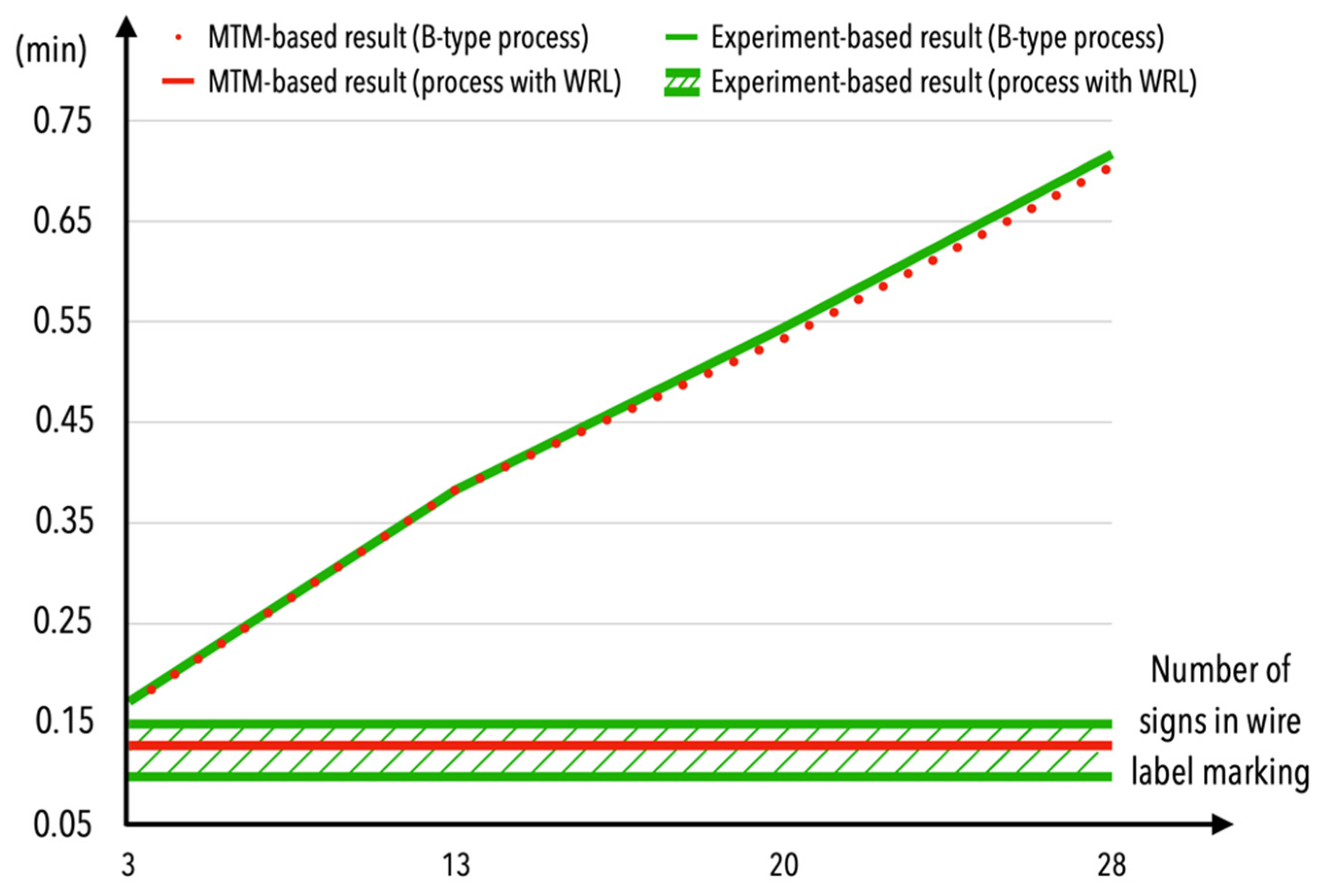
| MTM-based result: | 0.70547 | MTM-based result: | 0.70459 | 0.53339 | 0.38359 | 0.16959 | MTM-based result: | 0.12866 |
| Experiment-based result: | Not analyzed | Experiment-based result: | 0.71667 | 0.54444 | 0.38333 | 0.17222 | Experiment-based result: | 0.10000 ÷ 0.15000 |
| Assembly with the WLR | ||
|---|---|---|
| Process time (h) | MTM-based result: | 0.64330 |
| Experiment-based result: | 0.75000 | |
| Energy consumption (kWh): | MTM-based result: | 0.00772 |
| Experiment-based result: | 0.00900 | |
| Cost of energy consumption (EUR/kWh): | MTM-based result: | 0.00165 |
| Experiment-based result: | 0.00192 | |
Publisher’s Note: MDPI stays neutral with regard to jurisdictional claims in published maps and institutional affiliations. |
© 2021 by the authors. Licensee MDPI, Basel, Switzerland. This article is an open access article distributed under the terms and conditions of the Creative Commons Attribution (CC BY) license (https://creativecommons.org/licenses/by/4.0/).
Share and Cite
Szajna, A.; Kostrzewski, M.; Ciebiera, K.; Stryjski, R.; Woźniak, W. Application of the Deep CNN-Based Method in Industrial System for Wire Marking Identification. Energies 2021, 14, 3659. https://0-doi-org.brum.beds.ac.uk/10.3390/en14123659
Szajna A, Kostrzewski M, Ciebiera K, Stryjski R, Woźniak W. Application of the Deep CNN-Based Method in Industrial System for Wire Marking Identification. Energies. 2021; 14(12):3659. https://0-doi-org.brum.beds.ac.uk/10.3390/en14123659
Chicago/Turabian StyleSzajna, Andrzej, Mariusz Kostrzewski, Krzysztof Ciebiera, Roman Stryjski, and Waldemar Woźniak. 2021. "Application of the Deep CNN-Based Method in Industrial System for Wire Marking Identification" Energies 14, no. 12: 3659. https://0-doi-org.brum.beds.ac.uk/10.3390/en14123659