Article

Dynamical Operation Based Robust Nonlinear Control of DC Microgrid Considering Renewable Energy Integration

1
Department of Electrical Engineering, Jouf University, Sakaka 72388, Saudi Arabia
2
School of Electrical Engineering and Computer Science (SEECS), National University of Sciences and Technology (NUST), Islamabad 44000, Pakistan
3
School of Electrical Engineering, Shandong University, Jinan 250061, China
4
School of Electrical Engineering, The University of Faisalabad (TUF), Faisalabad 38000, Pakistan
*
Author to whom correspondence should be addressed.
Submission received: 24 May 2021 / Revised: 26 June 2021 / Accepted: 27 June 2021 / Published: 2 July 2021
(This article belongs to the Special Issue Solar and Wind Power and Energy Forecasting Ⅱ)

Abstract

:
The importance of microgrids has been acknowledged with the increasing amount of research in direct current (DC) microgrids. The main reason for this is the straightforward structure and efficient performance. In this research article, double integral sliding mode controllers (DISMCs) have been proposed for energy harvesting and DC microgrid management involving renewable sources and a hybrid energy storage system (HESS). DISMC offers a better dynamic response and reduced amount of chattering than the traditional sliding mode controllers. In the first stage, the state differential model for the grid was derived. Then, the nonlinear control laws were proposed for the PV system and hybrid energy storage system to achieve the main objective of voltage regulation at the DC link. In the later part, the system’s asymptotic stability was proven using Lyapunov stability criteria. Finally, an energy management algorithm was provided to ensure the DC microgrid’s smooth operation within the safe operating limit. The proposed system’s effectiveness was validated by implementing on MATLAB/Simulink software and comparing against sliding mode control and Lyapunov redesign. Moreover, to ensure the proposed controller’s practical viability for this scheme, it has been tested on real-time hardware-in-the-loop test bench.

1. Introduction

The increased use of power from traditional sources has contributed enormously to environmental pollution [1]. Much research has been conducted in recent years to reduce the dependence on traditional power generation systems. A major milestone has been achieved by using renewable energy sources in distributed generation systems [2]. This had greatly helped in reducing greenhouse gases along with its increased energy efficiency. Conversely, the independent use of renewable energy sources (RESs) is not appreciated due to its unpredictable output [3]. Hence, a group of energy storage systems (ESSs) to counter renewables’ intermittent nature are required [4].
The distributed generation (DG) systems used currently have either PV or wind as an energy source, but a combination of both has been considered in [5,6]. With the use of multiple renewable sources and optimization of storage units’ size, the cost for storage units can be minimized greatly [7]. The high energy density of batteries allow them to store a large amount of energy. However, as battery are a low power density device, they cannot compensate for the transients during load variation; hence, a high power density unit is required. The cumulative operation of the battery with an ultracapacitor (UC) would be able to serve the purpose [8,9]. The battery will be used as a high storage element and UC to supply the power transients; hence, stabilizing the power dynamics.
With the advances in global technology, microgrids are gaining popularity in this modern era. A microgrid can be either DC or a combination of AC and DC. The systems involving renewable sources, power converters, and modern loads require DC power for their operation; hence, a DC microgrid is preferred [10,11]. Moreover, the reduced complexity in its structure, high energy efficiency, isolated operating mode, and regular power supply to rural areas make it a suitable choice [12,13]. To attain a balanced energy and regulated operation of a DC microgrid, a complex control algorithm is required. Various control methods for energy management in AC microgrids have been studied in [14,15,16,17,18] but they cannot be directly linked to DC microgrids in light of the aforementioned facts. The main control objective in DC microgrids is to achieve a stable voltage at the DC link using the indirect voltage regulation method [19]. To the best of our knowledge, a limited number of research studies has been proposed on the control of renewable-based microgrids with a multisource hybrid energy storage system [20,21].
Various linear controllers are applied in the DC microgrid to regulate the output voltage considering the stability of the system [22,23,24]. Moreover, to address the system uncertainties, robust H control has been proposed in [25,26], making the system’s functionality smooth, but no detailed stability analysis has been done. Droop Control is an effective control method for stable output voltage and has been used with an adaptation parameter in [27]. The system is multisource with varying state of charges (SoCs), has dynamical behavior and is not catered to using Adaptive droop control. The controllers proposed so far can stabilize the system with regulated output but because the DC–DC converters used are intrinsically nonlinear, the system has been linearized around a specific equilibrium point and hence the functionality of the system is limited. Therefore, linear control techniques are not suitable for a system with sharp and continuous variations.
Multiple control strategies in terms of nonlinear controllers are applied to the proposed system for regulated DC bus voltage and stable operation [28,29,30,31,32]. In [13], the terminal sliding mode control (SMC) has been used for a microgrid, but the system is prone to external disturbances and has inherited chattering effects. A backstepping control method has been used in [33] but is limited to a single renewable energy source. A feedback control mechanism was proposed in [34] to attain the desired output but the system is limited to the localized stability and hence the performance of the system is degraded. In [35], a control Lyapunov function (CLF)-based nonlinear controller was proposed for a DC microgrid system but no systematic approach for ensuring power balance was performed. The optimal control schemes considering the robustness of the system are detailed in [36]. This may have an adverse effect on the system performance during the systematic shift from RESs to a hybrid energy storage system. Decentralized methods for control of DC microgrids are presented in [37,38]. The general model of DC microgrid depicted in Figure 1 consists of a PV-based generation system linked directly to a DC–DC converter and a hybrid energy storage system comprising of a battery and ultracapacitor was directly linked to the DC bus with two DC–DC converters. Here P b a t , P s c , V b a t , V s c , I b a t , I s c and S o C b a t , S o C s c represent the power, voltage, current and state of charge of the battery and ultracapacitor, respectively. u 23 and u 45 denote the nonlinear control signals. Furthermore, the state variables, sliding surfaces and errors are shown by X i , S i , and e i , respectively.
The main contribution and innovation of this paper is to design a controller that can enhance the overall dynamic response of a system and regulate the output voltage for the stable operation of the microgrid including a renewable energy system. Moreover, chattering in many of the previously implemented controllers motivated us to design a robust nonlinear controller to cater for all these difficulties in an efficient way and make the system robust to disturbances and noise. To the best of our knowledge, this work is new and has not been discussed in the literature in terms of the considered topology with such an advanced controller and HIL test. Furthermore, SMC is thought to be a good controller with finite time convergence and robust to disturbances and uncertainties but it has the inherent problem of chattering, which can be reduced by higher-order SMC. This includes the addition of single-integral and double-integral actions. DISMC is thought to be a better robust controller in terms of transient responses and removal of chattering. The superiority of the proposed DISMC as compared to SMC is guaranteed by two dominant factors. The integral term, which reduces the chattering and provides a robust response against disturbances and reduced computational complexity, leads to easier real-time implementation. Moreover, a comparison of the proposed DISMC was provided against SMC and Lyapunov redesign controller and the simulation results were obtained to ensure its effectiveness.
The main objectives of this research work are as follows:
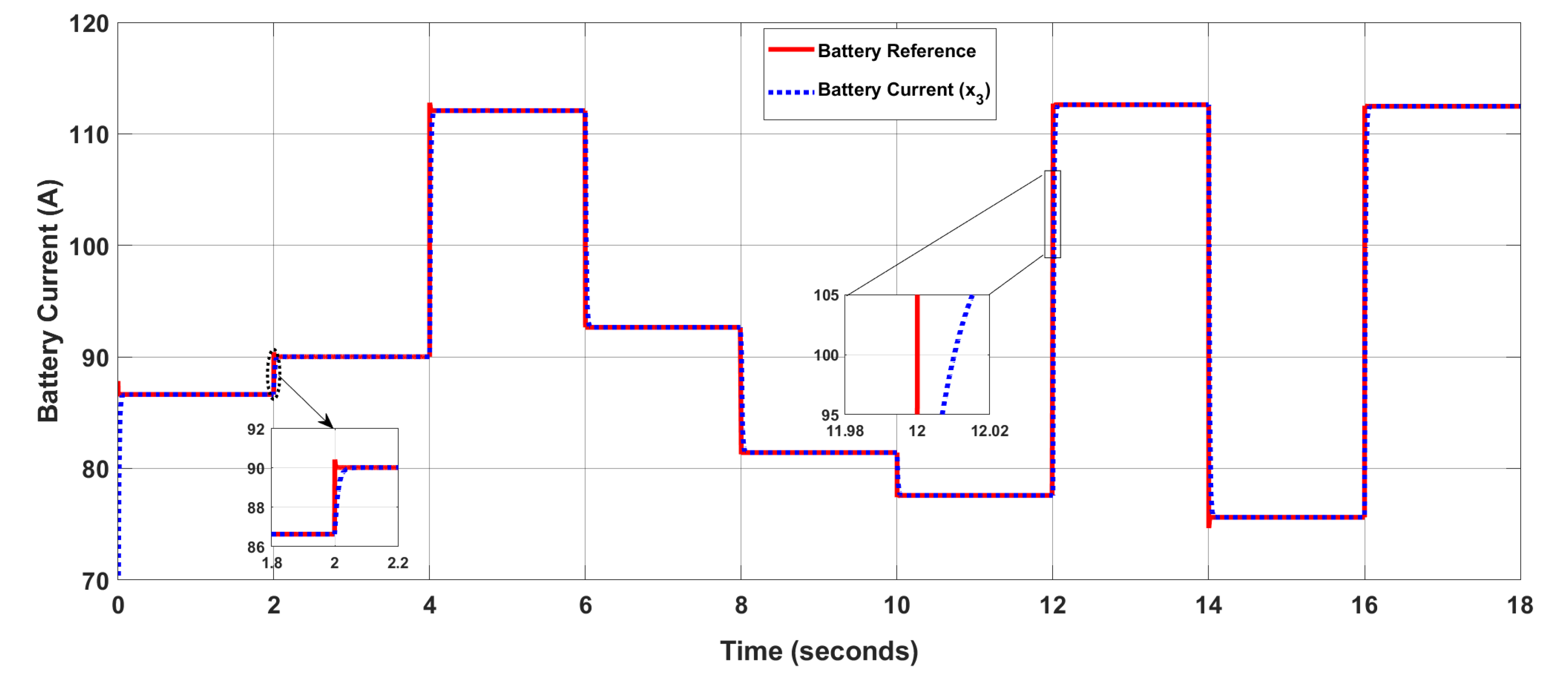
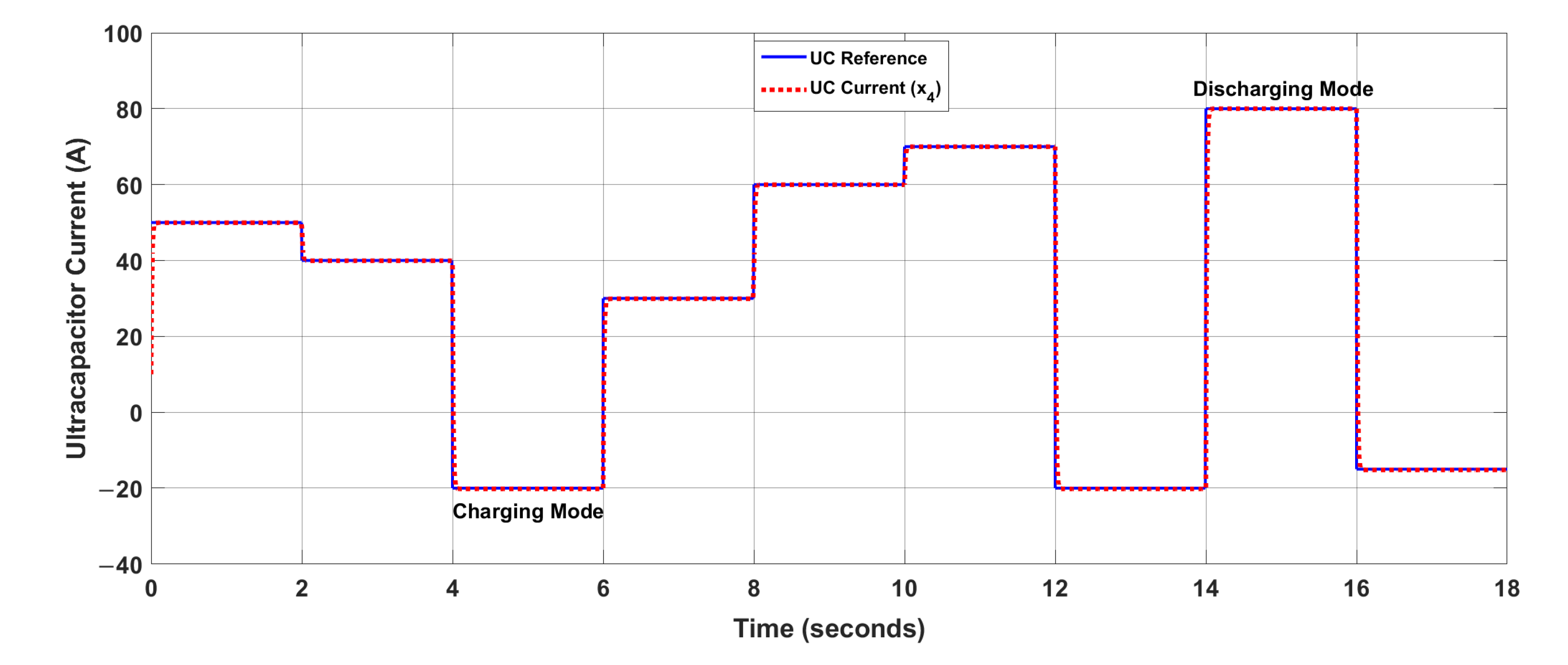
  • Output voltage regulation at DC link and regulated charging and discharging profile for the primary and secondary sources irrespective of the variation in load demand and renewable energy source.
  • Ensuring asymptotic stability of the DC microgrid under different operating conditions.
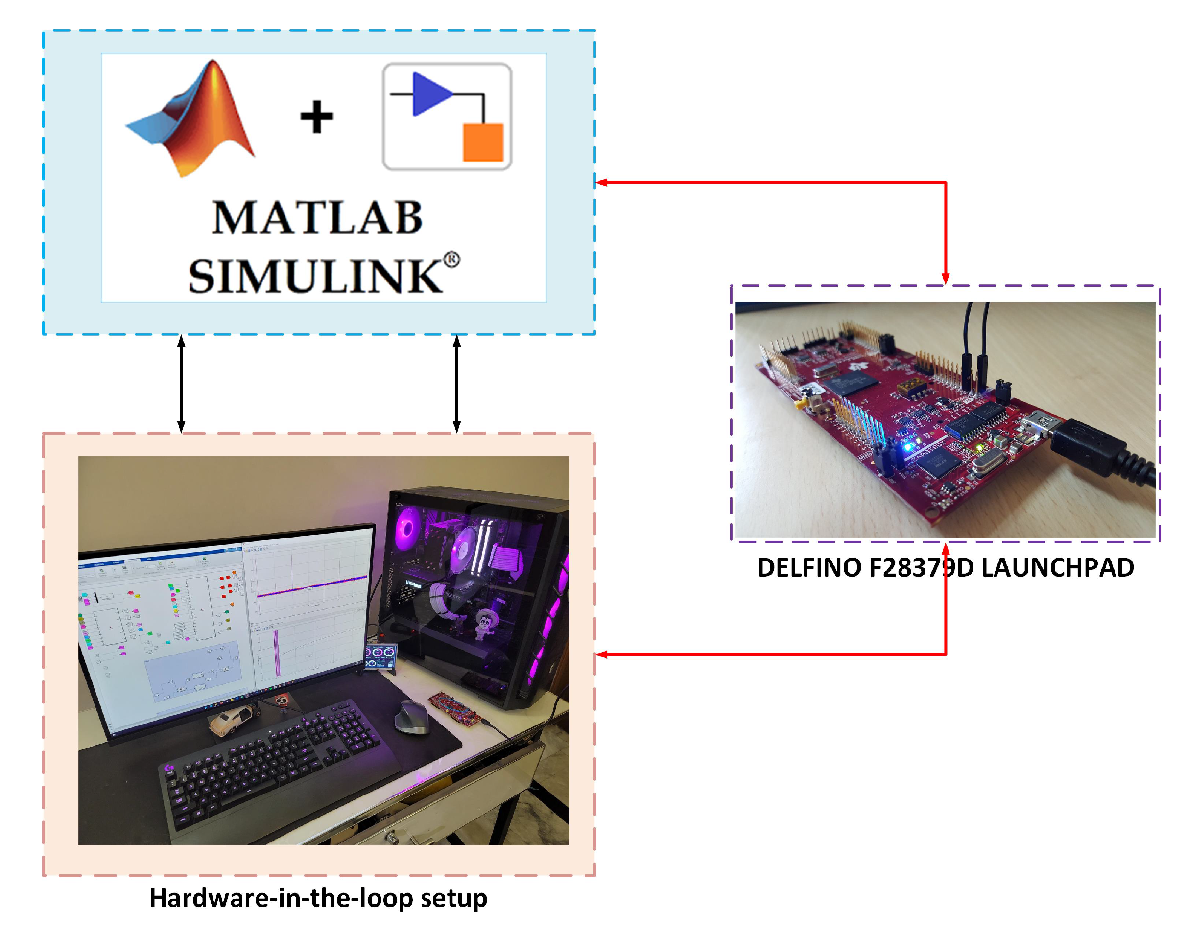
  • Validate the effectiveness of the proposed system using controller hardware-in-the-loop setup.
  • Estimation of the gains using a genetic algorithm for the optimal approximation of the controller gains.
The remaining paper is organized as follows: Section 2 contains the mathematical modelling of the DC microgrid. Section 3, encloses the controller design for considered DC–DC power converters. In Section 4, simulation and real-time results are presented to identify the superiority of the proposed controller. Finally, Section 5 details the conclusions.

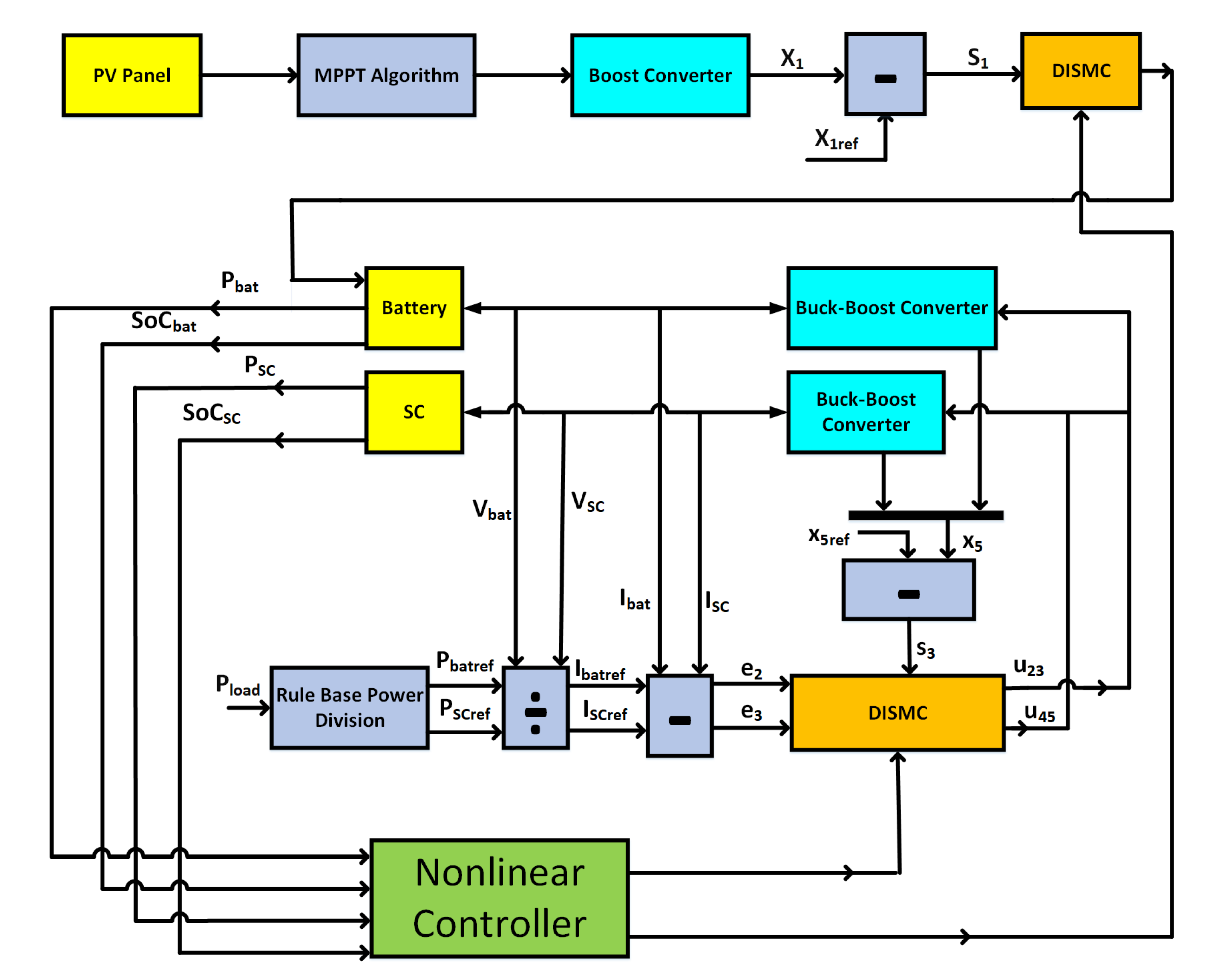
2. Mathematical Representaion of DC Microgrid

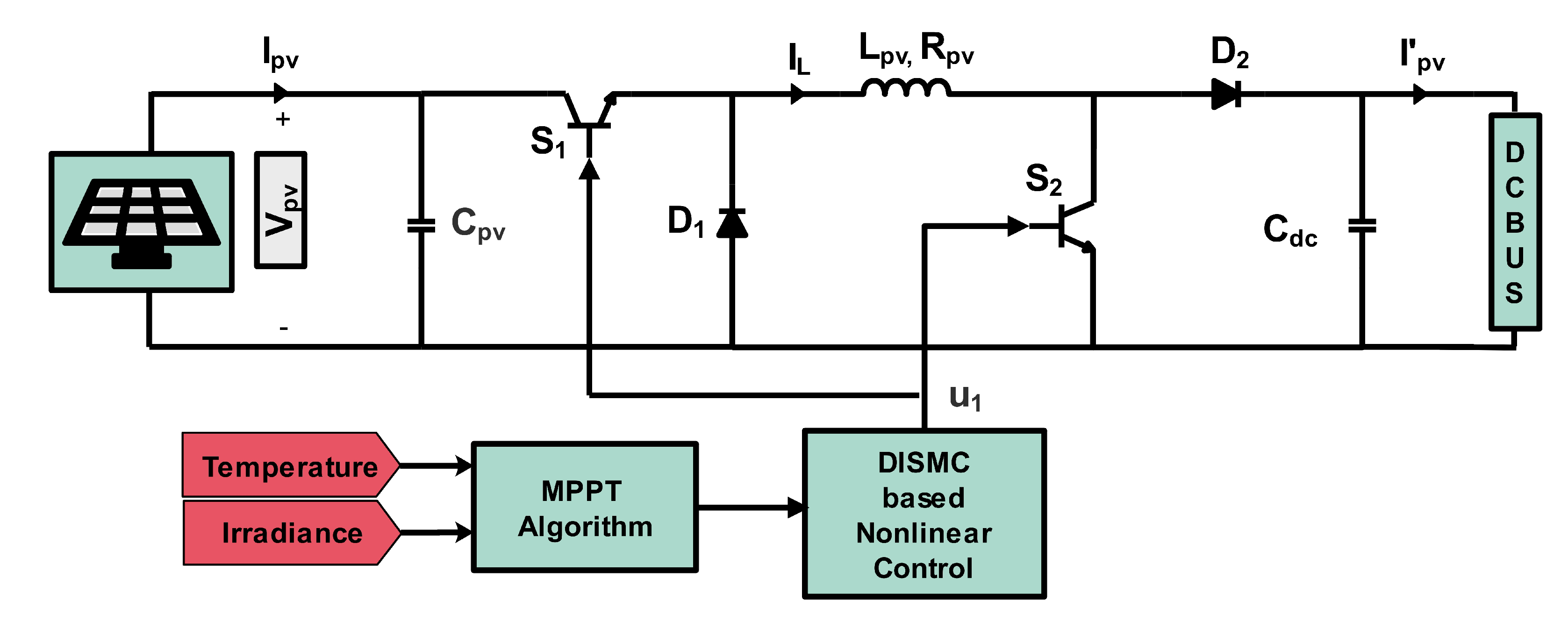
2.1. Modelling of PV Based Energy Generation System

The considered PV setup consists of a PV panel and a non-inverting bidirectional buck-boost converter, as depicted in Figure 2. The converter performance is optimized by operating at maximum power point and OFF-maximum power point state as directed by the supervisory control. To obtain the reference value under maximum power point tracking (MPPT), the regression plane method utilizes the temperature and irradiance as time-varying input [39]. By using the following equation, the reference value for PV voltages can be obtained:
V p v r e f = 322 ( 1.34 t e m p e r a t u r e ) ( 0.00964 I r r a d i a n c e )
The component-wise breakdown of the DC–DC converter used for a PV system is represented in Figure 2. It comprises of two BJTs acting as a switch ( S 1 , S 2 ), two diodes labeled as ( D 1 , D 2 ), an inductor L p v , input capacitor C p v and an output filtering capacitor C d c . The converter was assumed to be operating in continuous conduction mode (CCM). The positioning of the switches is directly dependent on the PWM signal generated by a nonlinear controller. When the switch S 1 and S 2 is at the ON state, the diode D 1 is reverse-biased and the system operates at the OFF load condition. Conversely, when both the switches are OFF, the diode D 1 is forward-biased and the system operates at the ON state and the output of the PV will be reflected across the filtering capacitor C d c .
The state dynamical model of the PV system is represented using the following set of differential equations:
V ˙ p v = I p v C p v I L C p v u 1
I ˙ L = V d c L p v u 1 V d c L p v u 1 + V p v L p v
Here, V p v are the average values of PV input voltages and I L is the input PV current, whereas output PV voltage V P V will be cumulatively considered across the energy storage unit due to the availability of a common DC bus. u 1 is the PWM signal generated by the nonlinear controller.

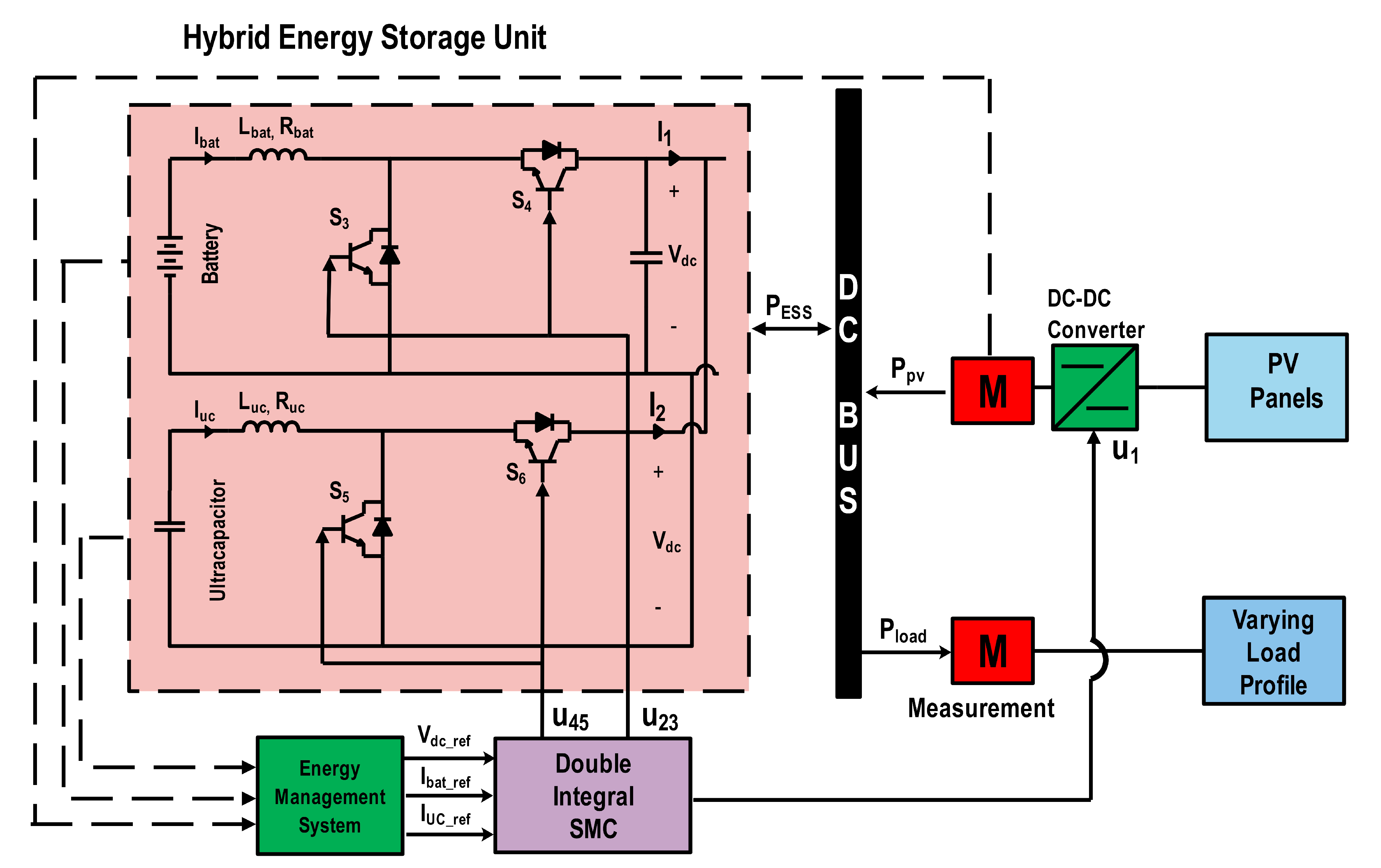
2.2. State Representation of Hybrid Energy Storage System

The component-wise representation of a hybrid energy storage system including DC–DC converters is presented in Figure 3. Two energy storage elements, battery and ultracapacitor, have been used. As both sources are capable of charging and discharging, they are connected directly to the bidirectional buck-boost converter. These DC–DC converters are linked directly to the DC bus. The bidirectional converter interfaced with the battery consists of two BJTs S 3 and S 4 acting as a switches, an output filtering capacitor C d c and an inductor L b a t with series internal resistance, R b a t . Similarly, the bidirectional DC–DC buck-boost converter attached to the ultracapacitor consists of switches S 5 and S 6 and an inductor L u c with series internal resistance, R u c . To regulate the DC bus, the BJTs are controlled directly via a nonlinear PWM signal.
To fulfill the load demand by using a battery as a primary source, the following equation needs to be ensured:
F = 1 , if ( I b a t r e f > 0 ) 0 , if ( I b a t r e f < 0 )
Here, I b a t r e f denotes the reference current generated by the battery, which will be used further to estimate the SoC and health of the battery.
As the DC–DC converter utilized is bidirectional, it will shift its state of operation depending on the load profile. When a pulse is applied to the switch S 3 , the converter tends to operate at boost mode with I b a t r e f > 0. Conversely, when the converter is to operate at buck mode, the PWM signal needs to be applied at switch S 3 , resulting in I b a t r e f < 0 to hold the power equilibrium. Furthermore, to approximate the state dynamical model of battery, inductor volt second and capacitor charge balance theorems are used.
I ˙ b a t = V b a t L b a t R b a t L b a t I b a t ( 1 u 2 ) V d c L b a t
V ˙ d c = ( 1 u 2 ) I b a t C d c I 1 C d c
I ˙ b a t = V b a t L b a t R b a t L b a t I b a t u 3 V d c L b a t
V ˙ d c = u 3 I b a t C d c I 1 C d c
Here, V b a t and I b a t are battery voltage and battery current, respectively, whereas I 1 and V d c are output current and DC bus voltage, respectively. u 2 and u 3 are the nonlinear control signals. Now, to obtain the compact model, a virtual control input u 23 has been defined as follows:
u 23 = [ F ( 1 u 2 ) + ( 1 F ) u 3 ]
The state model can hence be redefined using Equation (10) as follows:
I ˙ b a t = V b a t L b a t R b a t L b a t I b a t u 23 V d c L b a t
V ˙ d c = u 23 I b a t C d c I 1 C d c
An ultracapacitor is the auxiliary source used to supply the transient power during peak load demands along with the main source. The UC cannot be charged directly from the mains because of its ability to instantaneously charge and discharge. It can be charged from the excessive power from the main source. As the DC–DC converter used is quite similar to the one used with the battery, a symmetric pattern was considered in defining the state model for UC. The switching fact can be captured using the following equation:
G = 1 , if ( I s c r e f > 0 ) 0 , if ( I s c r e f < 0 )
Here, I s c r e f defines the reference current from the secondary source and is related to the current I 2 , which determines the contribution of the UC and is expressed as follows:
I 2 = ( 1 u 4 ) I u c
Here, u 4 represents the PWM signal applied at switch S 4 . To consider the charging and discharging characteristics of the UC, the following set of differential equations needs to be considered:
I ˙ u c = V u c L u c R u c L u c I u c ( 1 u 4 ) V d c L u c
I ˙ u c = V u c L u c R u c L u c I u c u 5 V d c L u c
I 2 = u 5 I s c
where u 5 represents the control input provided at switch S 5 . Moreover, the globalized model of the system can be achieved using the dual control defined as follows:
u 45 = [ G ( 1 u 4 ) + ( 1 G ) u 5 ]
The state model of the system is given as follows:
I ˙ u c = V u c L u c R u c L u c I u c u 45 V d c L u c
I 2 = u 45 I u c
Furthermore, to access the cumulative current at the DC line, Kirchhoff’s current rule is applied at the common node. According to Kirchoff’s current rule, the sum of the current flowing into the node must be equal to the sum of current flowing out of the node. Now, applying Kirchoff’s current rule and substituting the value of I 2 from Equation (19) yields:
I 1 = I o u 45 I u c
The state equation for V d c in a more compact pattern is obtained by placing the value of I 1 from Equation (20) in Equation (11) and incorporating the output voltage PV voltage V p v across C d c , which results in the following:
V ˙ d c = ( 1 u 1 ) I p v C d c + u 23 I b a t C d c + u 45 I s c C d c I o C d c
This equation represents the state equation for the DC bus voltage regulation of the DC microgrid.

2.3. Global State Dynamical Model of DC Microgrid System

The globalized state model was developed for the DC microgrid with PV as the renewable energy source and a battery and ultracapacitor as the storage elements. The state dynamical Equations (2), (3), (10), (18) and (21) are presented in a more simplified pattern, as elaborated using the following set of equations:
x ˙ 1 = I p v C p v x 2 C p v u 1
x ˙ 2 = x 1 L p v u 1 + x 5 L p v u 1 x 5 L p v
x 3 ˙ = V b a t L b a t R b a t L b a t x 3 u 23 x 5 L b a t
x 4 ˙ = V u c L u c R u c L u c x 4 u 45 x 5 L u c
x 5 ˙ = ( 1 u 1 ) x 2 C d c + u 23 x 3 C d c + u 45 x 4 C d c I o C d c
The states x 1 , x 2 , x 3 , x 4 and x 5 represent PV input voltage v p v , PV input current I L , battery current I b a t , UC current I u c and DC link voltages V d c . The nonlinear control inputs are defined as u 1 , u 23 and u 45 . As the state equations defined for multi-input-multi-output systems are nonlinear, a nonlinear controller needs to be designed to obtain the objectives.

3. Nonlinear Double-Integral SMC-Based Controller

3.1. Controller Design of DC–DC Converter for Renewable Energy Source

The converters associated with the energy supplying unit should be adequately controlled to ensure voltage regulation at the DC bus. Double-integral sliding mode control is a sequential and efficient approach for minimization of error in the steady-state and for the reduction of convergence time of a signal and robustness against transients in terms of load variations and bounded uncertainties. To ensure the efficient tracking of the charging voltage for the battery, the error e 1 in terms of state variable x 1 and its reference is defined as follows:
e 1 = x 1 V p v r e f
Taking the time derivative of e 1 defined in Equation (27) and substituting the value of x ˙ 1 from Equation (2) yields:
e ˙ 1 = I p v C p v u 1 x 2 C p v V ˙ p v r e f
Moreover, to reduce the chattering and steady-state error, the sliding surface with a double integral action is defined as follows:
S 1 = K 1 0 t 0 t e 1 d t d t + K 2 0 t e 1 d t + e 1
S ˙ 1 = K 1 0 t e 1 d t + K 2 e 1 + e ˙ 1
S ˙ 1 = K 1 0 t e 1 d t + K 2 e 1 + I p v C p v u 1 x 2 C p v V ˙ p v r e f
To achieve the control input, u 1 , the following condition must be satisfied:
ρ 1 | S 1 | θ 1 s a t ( S 1 λ 1 ) = K 1 0 t e 1 d t + K 2 e 1 + I p v C p v u 1 x 2 C p v V ˙ p v r e f
we considered, ρ i | S i | θ i s a t ( S i λ i ) , which is the reaching law of SMC. It is also known as the power rate reaching law, which accelerates the reaching speed when state values differ largely from those of the switching manifold. Here, ρ i represents the design parameters, with their values being any constant number. θ i are constant values bounded between 0 and 1. | S i | θ i ensures the fast convergence of the system to the sliding surfaces. Moreover, the chattering effect was minimized by the factor λ i [40].
The control input u 1 comes out to be:
u 1 = C p v x 2 K 1 0 t e 1 d t + K 2 e 1 + I p v C p v V ˙ p v r e f + ρ 1 | S 1 | θ 1 s a t ( S 1 λ 1 )
where 0 u 1 1. The control law presented in Equation (33) was used to generate the duty cycle for the charger. The obtained control law regulates the voltage of the integrated charging unit.

3.2. Nonlinear Controller Design of DC–DC Converters for Hybrid Energy Storage System

In this subsection, a double-integral sliding mode controller is presented for the energy management of a hybrid energy storage system and to achieve the design objectives. The coupled controllers are useful when dual-control techniques are required for the state model defined by Equations (10), (18) and (21). Now to ensure the finite time convergence, the respective errors are defined as follows:
e 2 = x 3 I b a t r e f
e 3 = x 4 I u c r e f
e 4 = x 5 V d c r e f
To consider the dynamics and finite time convergence of the energy storage system, the respective sliding surfaces are defined as:
S 2 = K 3 0 t e 2 d t + K 4 e 2 + e ˙ 2
S 3 = K 5 0 t e 3 d t + K 6 e 3 + e ˙ 3
S 4 = K 7 0 t e 4 d t + K 8 e 4 + e ˙ 4
Moreover, the integral action is necessary to reduce the chattering. Defining the integral term for reference generation of a battery and UC current and hence differentiating with respect to time results in the following expressions:
S ˙ 2 = K 3 0 t e 2 d t + K 4 e 2 + V b a t L b a t R b a t L b a t x 3 u 23 x 5 L b a t I ˙ b a t r e f
S ˙ 3 = K 5 0 t e 3 d t + K 6 e 3 + V u c L u c R u c L u c x 4 u 45 x 5 L u c I ˙ u c r e f
S ˙ 4 = K 7 0 t e 4 d t + K 8 e 4 + u 23 x 3 C d c I E S S u 45 x 4 C d c V ˙ d c r e f
To define the control inputs of DC–DC converters associated with energy storage elements, the following condition needs to be assured:
ρ 2 | S 2 | θ 2 s a t ( S 2 λ 2 ) = K 3 0 t e 2 d t + K 4 e 2 + V b a t L b a t R b a t L b a t x 3 u 23 x 5 L b a t I ˙ b a t r e f
The control input u 23 for the DC–DC converter linked with the battery is as follows:
u 23 = L b a t x 5 ( K 3 0 t e 2 d t + K 4 e 2 + V b a t L b a t R b a t L b a t x 3 I ˙ b a t r e f + ρ 2 | S 2 | θ 2 s a t ( S 2 λ 2 )
Now, to define the control input u 45 for a DC–DC converter associated with a UC source, the following condition needs to be satisfied:
ρ 3 | S 3 | θ 3 s a t ( S 3 λ 3 ) = K 5 0 t e 3 d t + K 6 e 3 + V u c L u c R u c L u c x 4 u 45 x 5 L u c I ˙ u c r e f )
The control input u 45 turns out to be:
u 45 = L u c x 5 ( K 5 0 t e 3 d t + K 6 e 3 V u c L u c R u c L u c X 4 I ˙ u c r e f + ρ 3 | S 3 | θ 3 s a t ( S 3 λ 3 ) )
The equation for the reference generation of DC link voltage is, therefore, defined as
V d c r e f = 1 s K 7 0 t e 4 d t + ( K 8 ) ( e 4 ) + u 23 x 3 C d c I E S S u 45 x 4 C d c + ρ 4 | S 4 | θ 4 s a t ( S 4 λ 4 )

3.3. Invariance and Stability Analysis

The invariance condition needs to be satisfied to obtain the bounded control inputs:
S 1 = 0 , S ˙ 1 = ρ 1 | S 1 | θ 1 s a t ( S 1 λ 1 )
S 2 = 0 , S ˙ 2 = ρ 2 | S 2 | θ 2 s a t ( S 2 λ 3 )
S 3 = 0 , S ˙ 3 = ρ 3 | S 3 | θ 3 s a t ( S 3 λ 3 )
S 4 = 0 , S ˙ 4 = ρ 4 | S 4 | θ 4 s a t ( S 4 λ 4 )
where the term | S i | θ i helps reduce the reaching time of the state. The value of θ needs to be between 0 and 1. As chattering is an inherited phenomenon of SMC and to overcome this issue, the boundary layer λ i needs to be incorporated. The value of λ needs not to be too small. The factor ρ i is termed as controller gain and it helps achieve fast convergence of the states. The greater the value of ρ , the faster the convergence but at the trade-off of computational cost. Here, i = 1 , 2 , 3 , 4 .
The sliding surface chosen must satisfy the existence condition ( S 1 ) S 1 ˙ < 0 and is expressed mathematically as
S 1 ˙ < 0 , if ( S 1 > 0 ) S 1 ˙ > 0 , if ( S 1 < 0 )
Now, for S 1 > 0 , u 1 = 1 :
K 1 0 t e 1 d t + K 2 e 1 + I p v C p v u 1 x 2 C p v V ˙ p v r e f < 0
For S 1 < 0 , u 1 = 0
K 1 0 t e 1 d t + K 2 e 1 + I p v C p v V ˙ p v r e f > 0
For the converter associated with a battery, the existence condition also needs to be satisfied: S 2 > 0 , u 23 = 1 which implies S ˙ 2 < 0
K 3 0 t e 2 d t + K 4 e 2 + V b a t L b a t R b a t L b a t x 3 x 5 L b a t I ˙ b a t r e f < 0
For S 2 < 0 , u 23 = 0 which implies S ˙ 2 > 0
K 3 0 t e 2 d t + K 4 e 2 + V b a t L b a t R b a t L b a t x 3 I ˙ b a t r e f > 0
Now, the existence condition for the UC comes out to be: S 3 > 0 , u 45 = 1 which implies S ˙ 3 < 0
K 5 0 t e 3 d t + K 6 e 3 + V u c L u c R u c L u c x 3 x 5 L u c I ˙ u c r e f < 0
S 3 < 0 , u 45 = 0 which implies S ˙ 3 > 0
K 5 0 t e 3 d t + K 6 e 3 + V u c L u c R u c L u c x 3 I ˙ u c r e f > 0
Now when S 4 > 0 , u 23 = 1 , u 45 = 0 , which implies S ˙ 4 < 0
K 7 0 t e 4 d t + K 8 e 4 + x 4 C d c I E S S C d c V ˙ d c r e f < 0
Also for S 3 < 0 , u 23 = 0 , u 45 = 1 , which implies S ˙ 4 > 0
K 7 0 t e 4 d t + K 8 e 4 + x 4 C d c I E S S u 45 x 4 C d c V ˙ d c r e f > 0
To ensure that the system works within the defined limit of operation, the Lyapunov candidate function has been defined as follows:
V = 1 2 S 1 2 + 1 2 S 2 2 + 1 2 S 3 2 + 1 2 S 4 2
The sliding surfaces S 1 , S 2 , S 3 and S 4 are defined in Equations (30) and (38)–(40).
V ˙ = S 1 S ˙ 1 + S 2 S ˙ 2 + S 3 S ˙ 3 + S 4 S ˙ 4
The time derivative of the Lyapunov function defined in Equation (62) needs to be strictly negative definite to ensure the finite time convergence and stability of the system. Now, substituting the value of rate of change of sliding surface in Equation (62) yields:
V ˙ = S 1 [ ρ 1 | S 1 | θ 1 s a t ( S 1 λ 1 ) ] + S 2 [ ρ 2 | S 2 | θ 2 s a t ( S 2 λ 2 ) ] + S 3 [ ρ 3 | S 3 | θ 3 s a t ( S 3 λ 3 ) ] + S 4 [ ρ 4 | S 4 | θ 4 s a t ( S 4 λ 4 ) ]
To eliminate the errors associated with the states, the gains of the controllers need to be greater than zero. A genetic-algorithm-based approach has been used to tune the gains to obtain the optimal results for the prescribed controller. The existence of the sliding surfaces has been defined in Equations (52)–(60). Hence, by using existence conditions, sliding coefficients, and optimal gain selection of the controllers, the stability of the system was guaranteed.
Remark 1.
The quadratic Lyapunov functions have been extensively used while deriving control laws for real-time applications due to their simple structure [41]. Use of a non-quadratic Lyapunov function proves to be a better choice for improved performance, as suggested in [42]. From the results in these research articles, it is obvious that the non-quadratic Lyapunov function improves the performance and robustness of the system as the proposed controllers are robust against external disturbances [43]. Hence, this fact needs to be investigated in the future work.

4. Simulation Results and Analysis

The performance of the proposed system has been assessed by simulating the system along with the proposed control scheme in MATLAB/Simulink (The MathWorks Inc., Natick, MA, USA). The physical and gain-tuning parameters are listed in Table 1, Table 2, Table 3, Table 4 and Table 5. The gains of the controller reflect the control effort required by the system to obtain the desired output. There are various techniques to calculate the gains of the controller, such as the trial and error method, neural network and machine-learning-based algorithms. The controller parameters listed in Table 3 were obtained using genetic-algorithm-based gain estimation for the tuning of gains. The specific parameters of the genetic algorithm are listed in Table 4. The reason for using the genetic algorithm for tuning of the gains is its balanced computational cost and reduced system complexity. Moreover, the efficient performance with balanced computation power motivated us to prefer it over other techniques. Genetic algorithm is an optimization method driven through natural evaluation. The performance index has been considered to be multi-objective, with equal weights assigned to the objective functions. The algorithm is basically divided into the following functions: create population, selection, reproduction, mutation, and reintegration into the population. The genetic algorithm was proposed considering the following functions: population, selection, reproduction and mutation. Initially, random population was proposed and the genetic algorithm selected the strongest genes using reproduction and mutation for a limited count of iterations before the final value was proposed. The size of the population is considered to be 100, maximum generations 50, crossover probability 0.08 and mutation probability 0.02. The strongest genes are those that reflect the best fitness curve. The parameters used in this process are summarized in Table 4.
All the controller parameters must be taken to be positive to ensure the stability of the system. The proposed scheme was validated using constant and varying load profiles at regular intervals and also by varying the temperature and irradiance of the PV system. The results obtained from the simulation work consist of varying temperature, irradiance, DC load profile, voltage regulation at DC bus, current tracking, and SoC of the contributing sources and are depicted sequentially in Figure 4, Figure 5, Figure 6, Figure 7, Figure 8, Figure 9, Figure 10, Figure 11, Figure 12, Figure 13, Figure 14, Figure 15, Figure 16 and Figure 17. Moreover, to ensure the effectiveness of the proposed controller, it has been compared with SMC and Lyapunov redesign (LR). The output for the varying temperature and irradiance of the PV panel obtained using Equation (32) can be observed in Figure 4 and Figure 5 respectively. The irradiance of the system was varied from 500 to 1000 (W/m 2 ), whereas the temperature was changed from 25 C to 40 C. The current and voltage of the PV panel can be observed in Figure 6 and Figure 7. To operate the PV system at MPPT, the increase in PV voltage results in decreased PV voltage. It is worthwhile to mention that the output power generated by the PV panel falls considerably if the temperature is increased. The main objective of the controller is to regulate the output voltage at the DC link. The DC bus voltage was adjusted to 1000 V and the simulation was executed for time t = 18 s. Furthermore, to observe the SoC of power sources, the Coulomb counting method was used, which is defined in the following set of equations [44]:
S o C B A T = S o C b a t 1 3600 C N i b a t d t
S o C U C = S o C u c 1 3600 C U C i u c d t
where i b a t and i u c represent the present current of the battery and ultracapacitor, respectively, whereas S o C B A T and S o C U C show the current SoC of the storage elements. The terms S o C b a t and S o C u c are the initial state of charge of power sources. Likely, C N and C u C are the nominal storage capacities of a battery and UC, respectively.

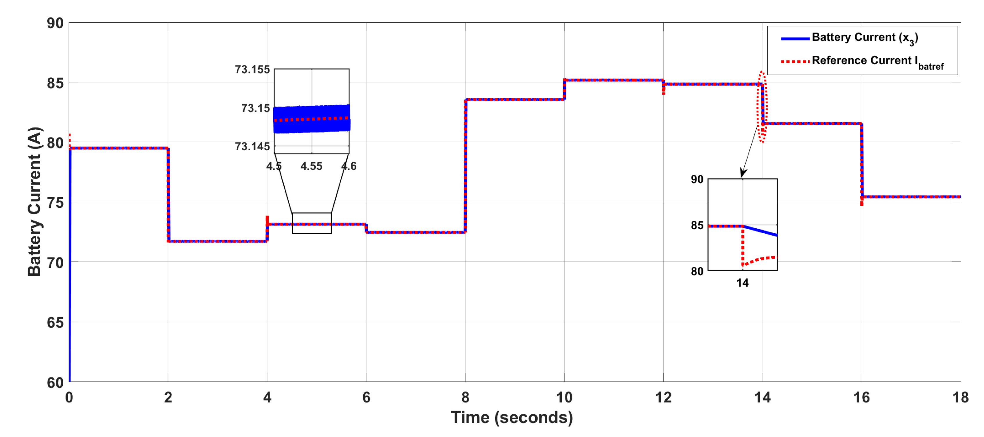
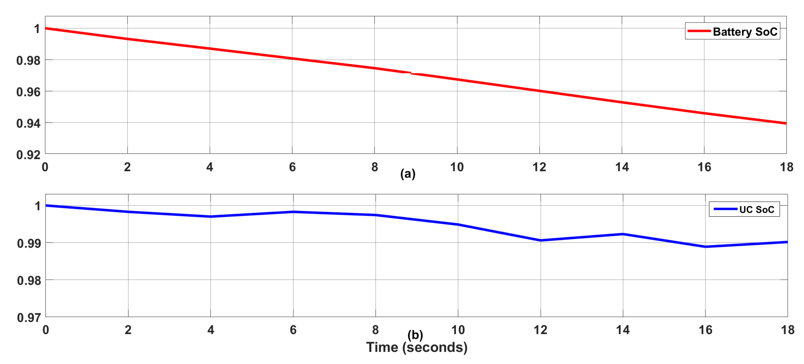
4.1. Results for Nonlinear Control of a Hybrid Energy Storage System

4.1.1. Case-I (Constant Load)

In this case, the load value is adjusted to 60 A, as depicted in Figure 8. As PV is the renewable energy source, it was operated under varying irradiance and temperature, as shown in Figure 4 and Figure 5. The output DC voltage was regulated at 1000 V using the proposed DISMC controller. For detailed analysis, the system was tested using SMC and LR controllers. It can be visualized from Figure 9 that no overshoot (OS)/undershoots (0% OS) and no chattering were observed for DISMC, whereas SMC and Lyapunov redesign reflect some regular peaks at t = 6 s and t = 12 s, with an overshoot of 9.9% and 11.4%, respectively. SMC is thought to be a good controller with finite time convergence and robust to disturbances and uncertainties but it has the inherent problem of chattering. The overshoots hence reflected are due to poor response of the controller, which can be reduced by higher-order SMC or by using a large control effort, which makes the system computationally complex and expensive. The current operating profile of a battery and UC in Figure 10 and Figure 11 shows that both the rechargeable sources are operated within the specified limit of operation, ensuring perfect reference tracking. It is clear from the figure that UC caters for the transient load, whereas the battery is operated under normal load conditions to ensure an extended life. From t = 6–12 s, power from the PV source falls, resulting in an increased stress on the hybrid energy storage system. As UC is the auxiliary source, it caters for the transient and hence limits the operation of the battery to have an extended life cycle. In addition, when sufficient power from the renewable energy source was included, the stress from the hybrid energy storage system reduced significantly. Finally, the SoC of battery and UC is depicted in Figure 12a,b, which is in exact accordance with the charge–discharge cycle of the energy storage elements.

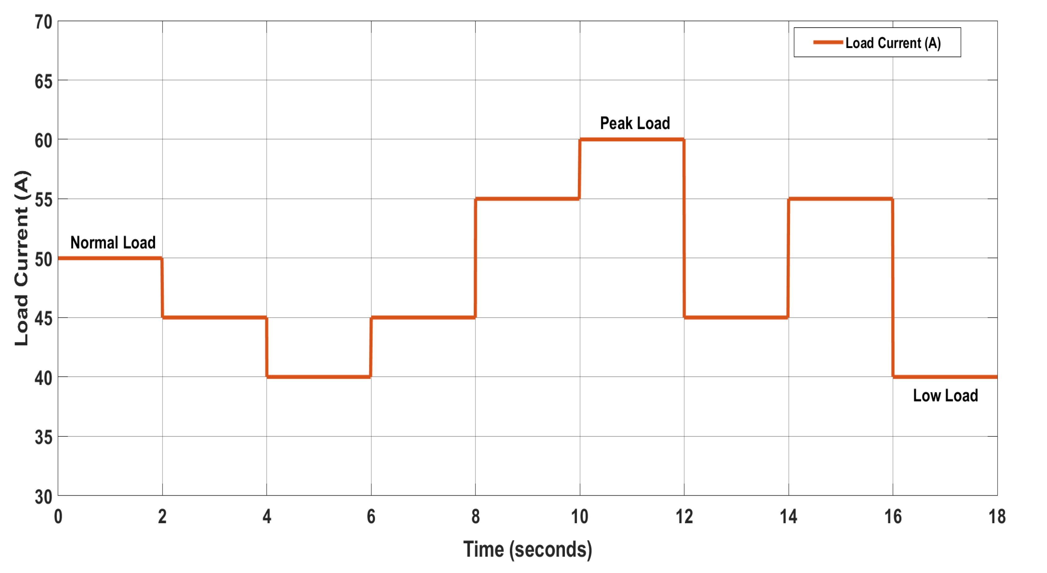
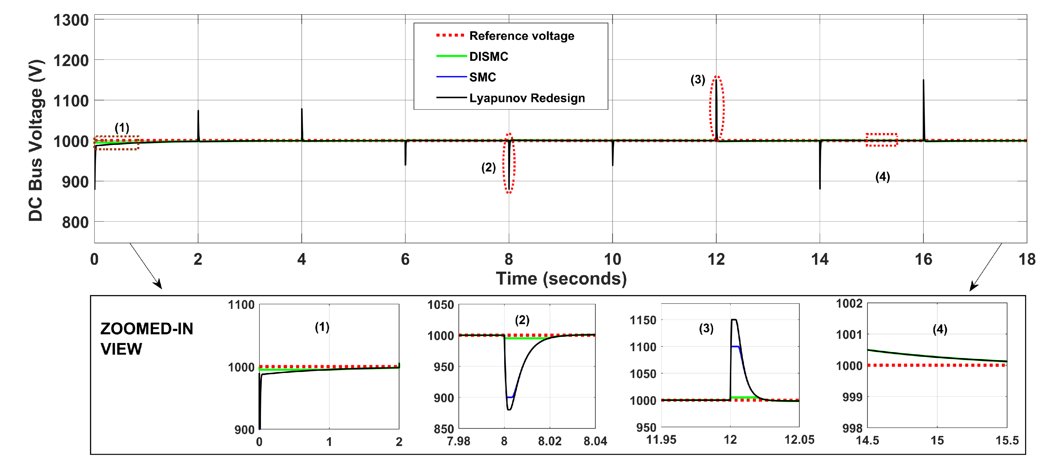
4.1.2. Case-II (Varying Load)

The selection of design characteristics for the system relates directly to the profile of the battery used in the microgrid. A battery with a large storage capacity demands a high-power balancing ability using complementary sources. The DC current load profile considered varies, as shown in Figure 13. The load current varied between 40 A and 60 A to reflect the high- and low-load states. The regulated DC bus with a voltage of 1000 V along with the proposed and comparison controllers is shown in Figure 14. It is pertinent to mention that the proposed DISMC controller outperforms the SMC and LR control, as a minute steady error of 0.0003% was observed as compared to the comparison controllers, which have a comparatively high steady-state error of 0.007% and 0.02%, respectively. During the instant variation of the load profile, no regular transients are seen for the proposed controller, whereas contrary to this, overshoots/undershoots of 9.9% and 11.4% were seen for SMC and LR controllers, respectively, as shown in Figure 14. Referring to the load profile depicted in Figure 13, the load current rises instantly to 60 A and hence there is a high current demand to be delivered by the power sources. As sufficient power cannot be supplied by PV alone due to cold startup, both the battery and UC need to be discharged together to fulfill the active load requirement, as shown in Figure 15 and Figure 16. At t = 2 s, as load demand falls from 50 A to 40 A, the battery begins to charge due to the availability of a bidirectional DC–DC converter, whereas PV and UC begin to supply the deficit power. At t = 12 s, as the load current falls from 60 A to 45 A, the UC starts to charge from the regenerative power, and the battery, as the current main power source, maintains the power balance by discharging. At t = 14 s, as the load current increases from 45 A to 55 A, all the renewable and storage elements discharge collectively to regulate the voltage at the DC bus. The absolute current tracking of the battery and UC using the proposed controller is shown in Figure 15 and Figure 16, respectively. It is important to note that the storage units operate within the safe limit of operation, hence reflecting the superiority of the proposed controller. It is pertinent to mention that the energy management algorithm has been truly followed to help to reduce the stress from the storage unit along with enhanced efficiency and life. Finally, the SoC of the battery and UC is depicted in Figure 17a,b, which is in exact accordance with the charge–discharge cycle of the energy storage elements. It is pertinent to mention that the value of SoC has been normalized between 0 and 1.

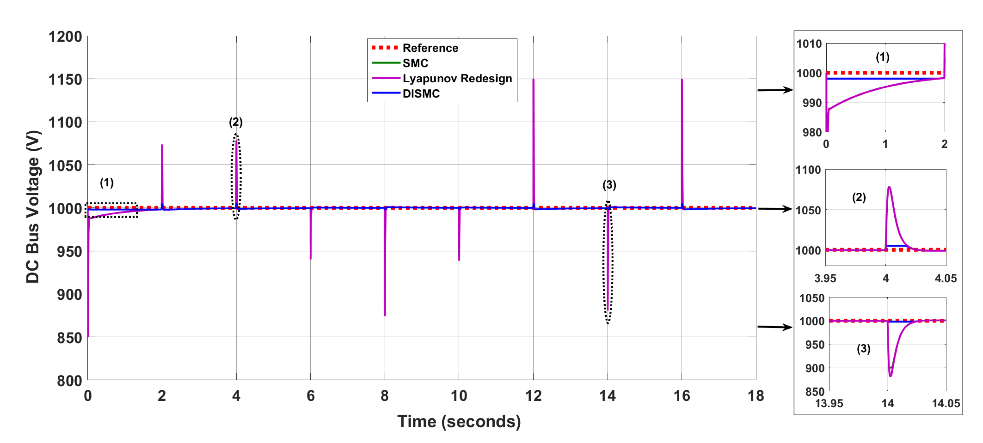
4.1.3. Controller Performance Comparison

To ensure the effective response of the proposed DISMC controller, it is compared against some standardized control techniques, such as SMC and Lyapunov redesign. Figure 14 shows the visual representation of the DC bus voltage for the proposed control scheme in comparison to others presented in the literature. A detailed analysis is presented in Table 5 for different control strategies to observe the performance parameters, which are rise time, settling time, overshoot (OS), and steady-state error (SSE). It is pertinent to mention that for voltage regulation at the DC bus; the rise time of the proposed controller is t = 0.00015 s, whereas for SMC, t = 0.04 s, and for Lyapunov-based control, t = 0.0026 s. Moreover, the settling time for SMC is quite impressive with t = 0.0002 s, for DISMC t = 0.00007 s and for Lyapunov-based control, t = 0.1 s. In addition, at t = 12 s, (Figure 14) an impressive response of the DISMC controller is observed in terms of OS and SSE due to the presence of double-integral action, resulting in 0% OS and reduced steady-state error. In contrast for SMC, an OS of 9.9% and a SSE of 0.007%. A significant OS 11.4% and a SSE of 0.02% for Lyapunov control due to the integration of a renwable energy source. Figure 14, shows a remarkable reduction in the chattering of DC bus voltage regulation due to double-integral action in DISMC, as compared to SMC and Lyapunov redesign control. It is worthwhile to mention that the proposed controller has an effectrive response in comparison to other controllers with minimum rise time, SSE and zero OS. Now, to ensure the real-time applicability of the proposed controller, it was tested using a hardware-in-the-loop test bench.

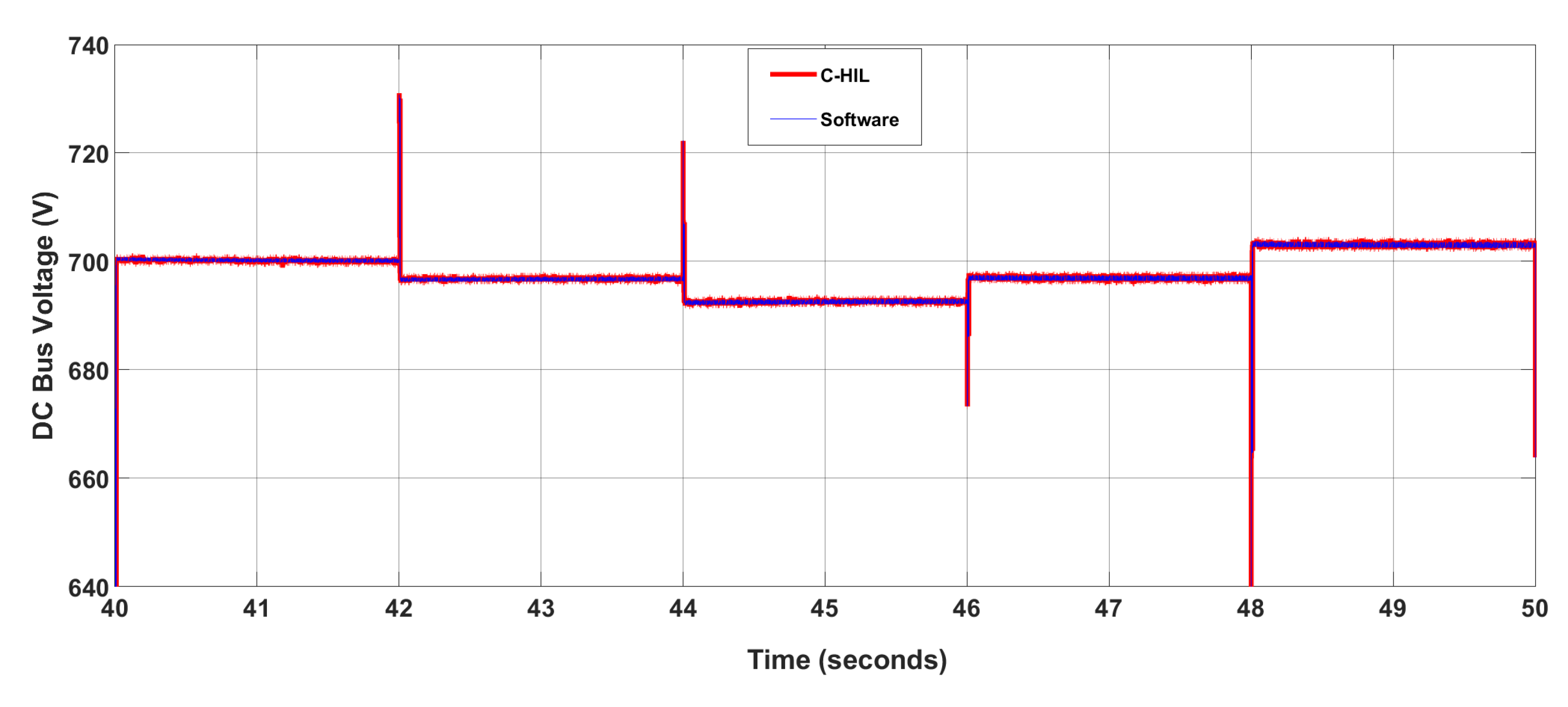
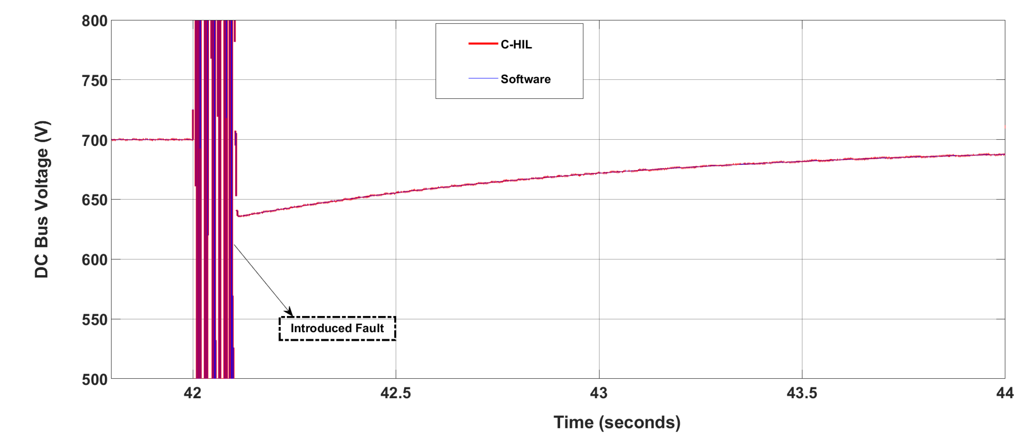
5. Experimental Validation (Hardware in the Loop)

The experimental setup for the controller hardware in the loop is shown in Figure 18 to analyze the real-time performance of the proposed controller scheme. For small-scale (HIL) implementation, MCUF28379D launchpads are utilized. These Launchpads consist of a TMS320F28379D dual-core high-frequency processor operating in the range of 200 MHz. The launchpads are connected directly to MATLAB using TI C2000 Delfino support from the embedded coder. The globalized state differential model of the DC microgrid was embedded on one Launchpad, whereas the control inputs of the proposed DISMC controller were burnt in the second Launchpad with a switching frequency of 10 kHz. The PWM output ports of the second Launchpad have been linked with GPIO ports of the Launchpad associated with the state model. A feedback-based closed link has been established with no direct link between ports of the Launchpad. Both the constant load and variable load cases of the simulated portion were repeated for C-HIL. The performance of the controller was verified by introducing a fault at the DC bus. The regulation voltage of the DC microgrid was adjusted to 700 V and the effectiveness of the proposed controller was observed. Figure 19 shows the voltage regulation of the DC bus at 700 V for a constant load profile (case-I). The efficient and finite time response of the controller was ensured. Figure 20 shows the regulated DC bus under dynamical load conditions (case-II). It is pertinent to mention that some transients have been observed at t = 42 s, 44 s, 46 s, and 48 s, during the rapid variations in the load profile, but are within the safe limit of operation. A slight variation from the reference value occurs during this load transition but the controller performs efficiently to cater this variation in a very short period.
Furthermore, in Figure 21, the robustness of the proposed DISMC controller was observed by introducing a fault for 0.1 s, falling in the time interval of t = 42 s to t = 42.1 s in the DC microgrid system. It is worthwhile to mention that the proposed control scheme is efficient enough to overcome the introduced fault within a minimum time of 1.5 s and regulates the DC bus voltage to a reference value of 700 V instantly. The fault introduced in the system has been removed by using the robust response of the proposed DISMC controller. The double-integral action and the signum function present in the SMC controller help deal with the introduced fault. When the reference value is changed due to a fault, the controller brings the value back to the original value of 700 V to minimize the steady-state error and to ensure asymptotic stability of the system. The proposed controller would be able to cater to all the uncertainties and disturbances within the certain bounds such that the asymptotic stability of the system is ensured. The results obtained from the C-HIL setup guarantee the effectiveness of the proposed DISMC controller.

6. Conclusions

In this research work, double-integral sliding mode controllers were developed for a renewable-generation-system-based DC microgrid to ensure smooth voltage regulation at the DC bus. The main advantage of using a DISMC controller is that we can enhance the overall dynamic response of a system, and regulate the output voltage for the stable operation of the system. Moreover, chattering in many of the previously implemented controllers motivated us to design a robust nonlinear controller to cater to all these difficulties in an efficient way and make the system robust against disturbances and noise. The performance of the proposed controller is very efficient with a rise time (0.0015 s), settling time (0.00007 s), percent overshoot (0%), and SSE (0.0003%) in comparison with SMC (0.04 s, 0.0002 s, 2.8% and 0.007%), and Lyapunov redesign control (0.0026 s, 0.1 s, 3.4% and 0.02%). Nonlinear controllers have been taken into account only because they cater for all the nonlinearities and rapidly changing behavior of the DC microgrid due to a renewable generation system. In addition, Lyapunov stability criteria were used to ensure dynamic stability of the system under varying power conditions. The performance of the proposed system was validated by testing against SMC and Lyapunov redesign controllers and implementing using MATLAB/Simulink software. The system was tested on a C-HIL test-bench to ensure the real-time applicability of the controller. It is pertinent to mention that the proposed controller results in improved performance of the system against transients and rapid variations in power demand. The future extension of this work is the realization of AC/DC microgrids using adaptive nonlinear controllers. Multi-input-multi-output converters can also be used to reduce the overall cost and losses of the system.

Author Contributions

Conceptualization and writing—original draft, A.A.; Writing—original draft and methodology, M.K.A.; Resources and supervision, M.Y.; Methodology and writing—review and editing, H.A.; Resources, software and visualization, M.H. and F.A. All authors have read and agreed to the published version of the manuscript.

Funding

The authors extend their appreciation to the Deputyship for Research Innovation, Ministry of Education in Saudi Arabia for supporting this research work through the project number 375213500.

Acknowledgments

The authors would like to extend their sincere appreciation to the central laboratory at Jouf University for supporting this study.

Conflicts of Interest

The authors declare no conflict of interest.

References

  1. Gejguš, M.; Aschbacher, C.; Sablik, J. Comparison of the Total Costs of Renewable and Conventional Energy Sources; Research Papers Faculty of Materials Science and Technology Slovak University of Technology: Trnava, Slovakia, 2016; Volume 24, pp. 99–104. [Google Scholar]
  2. Dreidy, M.; Mokhlis, H.; Mekhilef, S. Inertia response and frequency control techniques for renewable energy sources: A review. Renew. Sustain. Energy Rev. 2017, 69, 144–155. [Google Scholar] [CrossRef]
  3. Desideri, U.; Yan, J. Clean Energy Technologies and Systems for a Sustainable World; Applied Energy: Perugia, Italy, 2012. [Google Scholar]
  4. Wu, T.; Ye, F.; Su, Y.; Wang, Y.; Riffat, S. Coordinated control strategy of dc microgrid with hybrid energy storage system to smooth power output fluctuation. Int. J. -Low-Carbon Technol. 2020, 15, 46–54. [Google Scholar] [CrossRef] [Green Version]
  5. Armghan, H.; Yang, M.; Armghan, A.; Ali, N. Double integral action based sliding mode controller design for the back-to-back converters in grid-connected hybrid wind-pv system. Int. J. Electr. Power Energy Syst. 2021, 127, 106655. [Google Scholar] [CrossRef]
  6. Armghan, H.; Yang, M.; Wang, M.; Ali, N.; Armghan, A. Nonlinear integral backstepping based control of a dc microgrid with renewable generation and energy storage systems. Int. J. Electr. Power Energy Syst. 2020, 117, 105613. [Google Scholar] [CrossRef]
  7. Aneke, M.; Wang, M. Energy storage technologies and real life applications—A state of the art review. Appl. Energy 2016, 179, 350–377. [Google Scholar] [CrossRef] [Green Version]
  8. Song, Z.; Hou, J.; Hofmann, H.; Li, J.; Ouyang, M. Sliding-mode and lyapunov function-based control for battery/supercapacitor hybrid energy storage system used in electric vehicles. Energy 2017, 122, 601–612. [Google Scholar] [CrossRef]
  9. Bai, Z.; Yan, Z.; Wu, X.; Xu, J.; Cao, B. H control for battery/supercapacitor hybrid energy storage system used in electric vehicles. Int. J. Automot. Technol. 2019, 20, 1287–1296. [Google Scholar] [CrossRef]
  10. Alanazi, A.; Lotfi, H.; Khodaei, A. Coordinated ac/dc microgrid optimal scheduling. In Proceedings of the 2017 North American Power Symposium (NAPS), Morgantown, WV, USA, 17–19 September 2017; pp. 1–6. [Google Scholar]
  11. Jia, H.; Mu, Y.; Qi, Y. A statistical model to determine the capacity of battery–supercapacitor hybrid energy storage system in autonomous microgrid. Int. J. Electr. Power Energy Syst. 2014, 54, 516–524. [Google Scholar] [CrossRef]
  12. Zhang, L.; Xiao, Y.; Zhu, Y. Voltage Segment Control of Wind/PV Hybrid Islanded DC Microgrid with Multiple Energy Storages; IET: Shanghai, China, 2019. [Google Scholar]
  13. Armghan, H.; Yang, M.; Armghan, A.; Ali, N.; Wang, M.; Ahmad, I. Design of integral terminal sliding mode controller for the hybrid ac/dc microgrids involving renewables and energy storage systems. Int. J. Electr. Power Energy Syst. 2020, 119, 105857. [Google Scholar] [CrossRef]
  14. Mahdavi, M.S.; Gharehpetian, G.; Ranjbaran, P.; Azizi, H. Frequencycregulation of AUT microgrid using modified fuzzy pi controller for flywheel energy storage system. In Proceedings of the 2018 9th Annual Power Electronics, Drives Systems and Technologies Conference (PEDSTC), Tehran, Iran, 13–15 February 2018; pp. 426–431. [Google Scholar]
  15. Villalón, A.; Rivera, M.; Salgueiro, Y.; Muñoz, J.; Dragičević, T.; Blaabjerg, F. Predictive control for microgrid applications: A review study. Energies 2020, 13, 2454. [Google Scholar] [CrossRef]
  16. Mehdi, H.; Salmasi, F.R. Robust optimal power management system for a hybrid AC/DC micro-grid. IEEE Trans. Sustain. Energy 2015, 6, 675–687. [Google Scholar]
  17. Teimour, H.; Kebriaei, H.; Salmasi, F.R. Decentralised robust TS fuzzy controller for a parallel islanded AC microgrid. IET Gener. Transm. Distrib. 2019, 13, 1589–1598. [Google Scholar]
  18. Wu, X.; Xu, Y.; He, J.; Wang, X.; Vasquez, J.C.; Guerrero, J.M. Pinning-based hierarchical and distributed cooperative control for ac microgrid clusters. IEEE Trans. Power Electron. 2019, 35, 9867–9887. [Google Scholar] [CrossRef]
  19. Komurcugil, H.; Biricik, S.; Guler, N. Indirect sliding mode control for dc–dc sepic converters. IEEE Trans. Ind. Inform. 2019, 16, 4099–4108. [Google Scholar] [CrossRef]
  20. Ravada, B.R.; Tummuru, N.R.; Ande, B.N.L. Photovoltaic-wind and hybrid energy storage integrated multi-source converter configuration for dc microgrid applications. IEEE Trans. Sustain. Energy 2020, 12, 83–91. [Google Scholar] [CrossRef]
  21. Yin, C.; Wu, H.; Locment, F.; Sechilariu, M. Energy management of dc microgrid based on photovoltaic combined with diesel generator and supercapacitor. Energy Convers. Manag. 2017, 132, 14–27. [Google Scholar] [CrossRef]
  22. Murdianto, F.D.; Nansur, A.R.; Hermawan, A.S.L.; Purwanto, E.; Jaya, A.; Rifadil, M.M. Modeling and simulation of mppt sepic-buck converter series using flower pollination algorithm (fpa)-pi controller in dc microgrid isolated system. In Proceedings of the 2018 International Electrical Engineering Congress (iEECON), Krabi, Thailand, 7–9 March 2018; pp. 1–4. [Google Scholar]
  23. Suresh, V.; Pachauri, N.; Vigneysh, T. Decentralized control strategy for fuel cell/pv/bess based microgrid using modified fractional order pi controller. Int. J. Hydrogen Energy 2021, 46, 4417–4436. [Google Scholar] [CrossRef]
  24. Zaheeruddin; Singh, K. Intelligent fractional-order-based centralized frequency controller for microgrid. IETE J. Res. 2020, 66, 1–15. [Google Scholar] [CrossRef]
  25. Sedhom, B.E.; El-Saadawi, M.M.; Elhosseini, M.A.; Saeed, M.A.; Abd-Raboh, E.E. A harmony search-based h-infinity control method for islanded microgrid. ISA Trans. 2020, 99, 252–269. [Google Scholar] [CrossRef] [PubMed]
  26. Sedhom, B.E.; El-Saadawi, M.M.; Hatata, A.Y.; Abd-Raboh, E.E. A multistage h-infinity–based controller for adjusting voltage and frequency and improving power quality in islanded microgrids. Int. Trans. Electr. Energy Syst. 2020, 30, e12143. [Google Scholar] [CrossRef]
  27. Matayoshi, H.; Kinjo, M.; Rangarajan, S.S.; Ramanathan, G.G.; Hemeida, A.M.; Senjyu, T. Islanding operation scheme for dc microgrid utilizing pseudo droop control of photovoltaic system. Energy Sustain. Dev. 2020, 55, 95–104. [Google Scholar] [CrossRef]
  28. Wang, S.; Lu, L.; Han, X.; Ouyang, M.; Feng, X. Virtual-battery based droop control and energy storage system size optimization of a dc microgrid for electric vehicle fast charging station. Appl. Energy 2020, 259, 114146. [Google Scholar] [CrossRef]
  29. Azeem, M.K.; Armghan, H.; Ahmad, I.; Hassan, M. Multistage adaptive nonlinear control of battery-ultracapacitor based plugin hybrid electric vehicles. J. Energy Storage 2020, 32, 101813. [Google Scholar] [CrossRef]
  30. Pradhan, R.; Subudhi, B. Double integral sliding mode MPPT control of a photovoltaic system. IEEE Trans. Control Syst. Technol. 2015, 24, 285–292. [Google Scholar] [CrossRef]
  31. Chen, Z.X.; Wang, J.; Ge, L.S.; Jiang, T.; Liu, Y.F.; Liu, Y.F. Double integral sliding mode control of paralleled dc/dc converters. In Proceedings of the 2015 IEEE 10th Conference on Industrial Electronics and Applications (ICIEA), Auckland, New Zealand, 15–17 June 2015. [Google Scholar]
  32. Li, P.; Guo, T.; Zhou, F.; Yang, J.; Liu, Y. Nonlinear coordinated control of parallel bidirectional power converters in an ac/dc hybrid microgrid. Int. J. Electr. Power Energy Syst. 2020, 122, 106208. [Google Scholar] [CrossRef]
  33. Yousefizadeh, S.; Bendtsen, J.D.; Vafamand, N.; Khooban, M.H.; Blaab-jerg, F.; Dragicevic, T. Tracking control for a dc microgrid feeding uncertain loads in more electric aircraft: Adaptive backstepping approach. IEEE Trans. Ind. Electron. 2018, 66, 5644–5652. [Google Scholar] [CrossRef] [Green Version]
  34. Davari, M.; Aghababa, M.P.; Blaabjerg, F.; Saif, M. A modular adaptive robust nonlinear control for resilient integration of vsis into emerging modernized microgrids. IEEE J. Emerg. Sel. Top. Power Electron. 2020, 9, 2907–2925. [Google Scholar] [CrossRef]
  35. Ahmadi, H.; Kazemi, A. The lyapunov-based stability analysis of reduced order micro-grid via uncertain lmi condition. Int. J. Electr. Power Energy Syst. 2020, 117, 105585. [Google Scholar] [CrossRef]
  36. Zhou, J.; Shi, M.; Chen, Y.; Chen, X.; Wen, J.; He, H. A novel secondary optimal control for multiple battery energy storages in a dc microgrid. IEEE Trans. Smart Grid 2020, 11, 3716–3725. [Google Scholar] [CrossRef]
  37. Tani, A.; Camara, M.B.; Dakyo, B. Energy management in the decentralized generation systems based on renewable energy—Ultracapacitors and battery to compensate the wind/load power fluctuations. IEEE Trans. Ind. Appl. 2014, 51, 1817–1827. [Google Scholar] [CrossRef]
  38. Babazadeh, M.; Karimi, H. A robust two-degree-of-freedom control strategy for an islanded microgrid. IEEE Trans. Power Deliv. 2013, 28, 1339–1347. [Google Scholar] [CrossRef]
  39. Iftikhar, R.; Ahmad, I.; Arsalan, M.; Naz, N.; Ali, N.; Armghan, H. Mppt for photovoltaic system using nonlinear controller. Int. J. Photo Energy 2018, 2018, 6979723. [Google Scholar] [CrossRef] [Green Version]
  40. Rahman, A.U.; Ahmad, I.; Malik, A.S. Variable structure-based control of fuel cell-supercapacitor-battery based hybrid electric vehicle. J. Energy Storage 2020, 29, 101365. [Google Scholar] [CrossRef]
  41. Zhang, Q.Q.; Wai, R.J. Robust Power Sharing and Voltage Stabilization Control Structure via Sliding-Mode Technique in Islanded Micro-Grid. Energies 2021, 14, 883. [Google Scholar] [CrossRef]
  42. Han, Y.; Ma, R.; Cui, J. Adaptive higher-order sliding mode control for islanding and grid-connected operation of a microgrid. Energies 2018, 11, 1459. [Google Scholar] [CrossRef] [Green Version]
  43. Mehdi, H.; Yazdanpanah, M.J. Performance enhanced model reference adaptive control through switching non-quadratic Lyapunov functions. Syst. Control Lett. 2015, 76, 47–55. [Google Scholar]
  44. Tummuru, N.R.; Mishra, M.K.; Srinivas, S. Dynamic energy management of renewable grid integrated hybrid energy storage system. IEEE Trans. Ind. Electron. 2015, 62, 7728–7737. [Google Scholar] [CrossRef]
Figure 1. General Architecture of a DC Microgrid.
Energies 14 03988 g001
Figure 2. Component-wise breakdown of a PV-based generation system.
Energies 14 03988 g002
Figure 3. Schematic representation of hybrid energy storage system.
Energies 14 03988 g003
Figure 4. Varying Temperature ( C) of PV.
Energies 14 03988 g004
Figure 5. Varying Irradiance (W/m 2 ) of PV.
Energies 14 03988 g005
Figure 6. PV Current under maximum power point tracking ( x 2 ) .
Energies 14 03988 g006
Figure 7. PV Voltage under maximum power point tracking.
Energies 14 03988 g007
Figure 8. Constant Load Current (case-I).
Energies 14 03988 g008
Figure 9. Voltage Regulation at DC Bus x 5 (case-I).
Energies 14 03988 g009
Figure 10. Battery current x 3 (case-I).
Energies 14 03988 g010
Figure 11. UC current x 4 (case-I).
Energies 14 03988 g011
Figure 12. (a) Case:I SoC of Battery (b) Case:I SoC of UC.
Energies 14 03988 g012
Figure 13. Varying Load Current (case-II).
Energies 14 03988 g013
Figure 14. Voltage Regulation at DC Bus x 5 (case-II).
Energies 14 03988 g014
Figure 15. Battery current x 3 (case-II).
Energies 14 03988 g015
Figure 16. UC current x 4 (case-II).
Energies 14 03988 g016
Figure 17. (a) Case:II SoC of Battery (b) Case:II SoC of UC.
Energies 14 03988 g017
Figure 18. Hardware-in-the-loop test bench.
Energies 14 03988 g018
Figure 19. HIL DC bus voltage regulation under constant load.
Energies 14 03988 g019
Figure 20. HIL DC bus voltage regulation under dynamical load.
Energies 14 03988 g020
Figure 21. HIL DC bus voltage regulation under induced fault.
Energies 14 03988 g021
Table 1. Parameters of renewable energy system.
PV Unit Specifications
Open loop voltage166 V
Close loop voltage17.5 V
Maximum power point voltage ( V m p p )300 V
Maximum power point current ( I m p p )15.2 A
Nominal power ouptput capacity1500 W
Table 2. Battery and supercapacitor parameters.
Battery Parameters
Battery typeLithium-Ion (Li-Ion)
Terminal voltage190–230 V
Rated current capacity13.9 Ah
Capacity per cell1.4 Ah
Battery arrayparallel: 25, series: 64
Supercapacitor Parameters
Nominal voltage205 V
Total capacitance2700 F
Initial SoC1
Current threshold−80–80 A
Supercapacitor arrayparallel: 20, series: 20
Table 3. Simulation parameters.
Circuit Parameters
Inductances L p v , L b a t , L u c 495 μ H, 1 mH, 1 mH
Capacitances C d c , C p o u t 95 nF, 70 mF
Resistances R p v R b a t , R u c ,0.5 m Ω , 10 m Ω , 10 m Ω
Switching frequency100 KHz
Controller Parameters
ρ 1 , ρ 2 , ρ 3 , ρ 4 9000, 900, 1000, 7700
K 1 , K 2 , K 3 , K 4 , K 5 ,0.1, 0.1, 0.1, 0.2, 0.2,
K 6 , K 7 , K 8 0.3, 0.3, 0.5
λ 1 , λ 2 , λ 3 , λ 4 0.96, 0.97, 0.98, 0.94
θ 1 , θ 2 , θ 3 , θ 4 0.03, 0.03, 0.02, 0.06
Table 4. Specific parameters of gain tuning algorithm.
Parameters of the Genetic Algorithm
Size of population100
Maximum generations50
Crossover probability0.8
Mutation probability0.02
Table 5. Comparison of controllers for performance indices.
Controller/ Performance Rise TimeSettling TimePercentage OvershootSteady State Error
Indices(s)(s)(%)(SSE) (%)
Lyapunov Redesign0.00260.111.40.02
SMC0.040.00029.90.007
DISMC0.00150.00007Nil0.0003
Publisher’s Note: MDPI stays neutral with regard to jurisdictional claims in published maps and institutional affiliations.

