
A Review of the Degradation of Photovoltaic Modules for Life Expectancy
by
 , , and
Jaeun Kim
1 ,
,
Matheus Rabelo
2,
Siva Parvathi Padi
1,
Hasnain Yousuf
3,
Eun-Chel Cho
3,* and
Junsin Yi
3,* 1
Department of Electrical and Computer Engineering, Sungkyunkwan University, Suwon 16419, Gyeonggi-do, Korea
2
Interdisciplinary Program in Photovoltaic System Engineering, Sungkyunkwan University, Suwon 16419, Gyeonggi-do, Korea
3
College of Information and Communication Engineering, Sungkyunkwan University, Suwon 16419, Gyeonggi-do, Korea
*
Authors to whom correspondence should be addressed.
Energies 2021, 14(14), 4278; https://0-doi-org.brum.beds.ac.uk/10.3390/en14144278
Submission received: 8 June 2021
/
Revised: 10 July 2021
/
Accepted: 12 July 2021
/
Published: 15 July 2021
(This article belongs to the Collection Review Papers in Solar Energy and Photovoltaic Systems)
Abstract
:Photovoltaic (PV) modules are generally considered to be the most reliable components of PV systems. The PV module has a high probability of being able to perform adequately for 30 years under typical operating conditions. In order to evaluate the long-term performance of a PV module under diversified terrestrial conditions, outdoor-performance data should be used. However, this requires a wait of 25 years to determine the module reliability, which is highly undesirable. Thus, accelerated-stress tests performed in the laboratory by mimicking different field conditions are important for understanding the performance of a PV module. In this paper, we discuss PV-module degradation types and different accelerated-stress types that are used to evaluate the PV-module reliability and durability for life expectancy before using them in the real field. Finally, prevention and correction measures are described to minimize economic losses.
1. Introduction
Renewable energy accounts for a significant and growing share of energy generation worldwide. Photovoltaic (PV) and wind technologies are expected to become the world’s largest source of energy by 2025, with photovoltaic modules representing 60% of the capacity additions [1]. PV-module reliability is becoming a major concern in a scenario where most PV-module manufacturers establish a 25 year or 30 year warranty contract with their customers [2]. PV-module manufacturers guarantee a power drop of less than 20% within the warranty period [3].
With such a long warranty time period, the degradation rates of the solar panels must be well defined and be below 0.8% per year. Recent studies have reported degradation rates of approximately 0.6–0.7% a year [3,4]. This degradation rate is still high, owing to the variability of the studied samples and considering that the degradation might increase over time. In addition, insufficient failure data are currently available for statistical analyses as most operating PV modules have not yet reached 25 years of operation [5]. Therefore, the degradation rate of many modules may exceed 0.7% a year, resulting in losses to manufacturers since they must comply with the warranty by providing a new module. Depending on the mechanism involved, the degradation of solar panels in the field can be long-term or short-term.
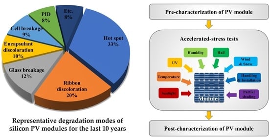
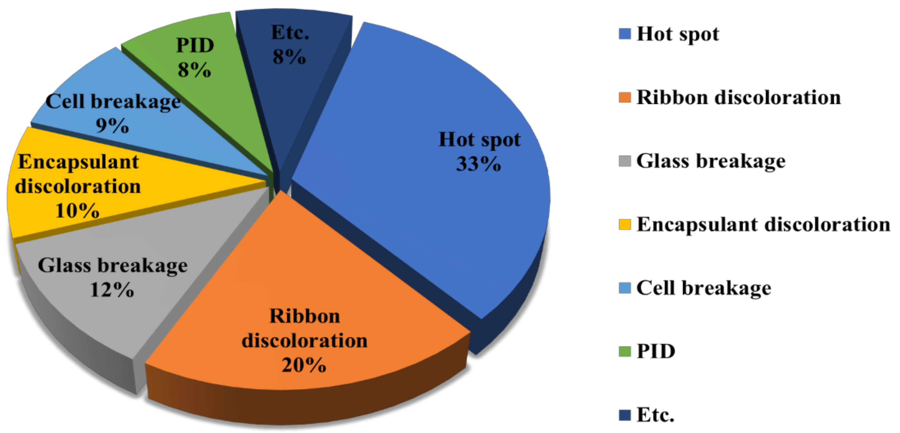
The dependability and lifespan of PV systems rely mostly on the efficiency of the PV system and its various degradation patterns [4,5]. PV-module failure information has been available since the early 1970s. According to data reported by the National Renewable Energy Laboratory (NREL) in 2017, as shown in Figure 1, the most common degradation modes in modules for the last 10 years were hot spots (33%) followed by ribbon discoloration (20%), glass breakage (12%), encapsulant discoloration (10%), cell breakage (9%), and potential-induced degradation (PID, 8%) [6].
Table 1 shows several modes and degradation rates reported in various countries in which most of the degradation is caused by environmental conditions, such as high humidity, extreme ambient temperatures, and exposure times of more than 10 years.
These modes are caused by stress along with humidity, ultraviolet (UV) radiation, temperature, wind, hail, and high system voltages as well as other factors such as broken interconnects, hot spots, corrosion, encapsulant discoloration, and delamination [20,21]. Research on the failure mode of the PV module that occurs frequently and the factors that affect it is being actively conducted in order to improve the reliability of the PV module [22,23,24,25,26]. If any of the PV-module components are replaced or removed from the field environment before its warranty period because of any type of failure and the power drops, those types of failures are called hard failures. Degradation losses are those that occur when the performance of the PV module degrades but still meets the warranty requirements [27]. The failure and degradation mechanisms in the PV module are mainly related to the construction/packaging/design and the operating environment.
In order to predict the lifetime of a solar module, it is necessary to analyze the major failure modes of the PV module. However, it is difficult for the manufacturer and stockholders to wait and observe failure and degradation losses before introducing new PV cells into the outdoor environment. Hence, a predictive model for the lifetime expectancy and a model for the performance of a new photovoltaic module are extremely significant for the producers as well as for the customers.
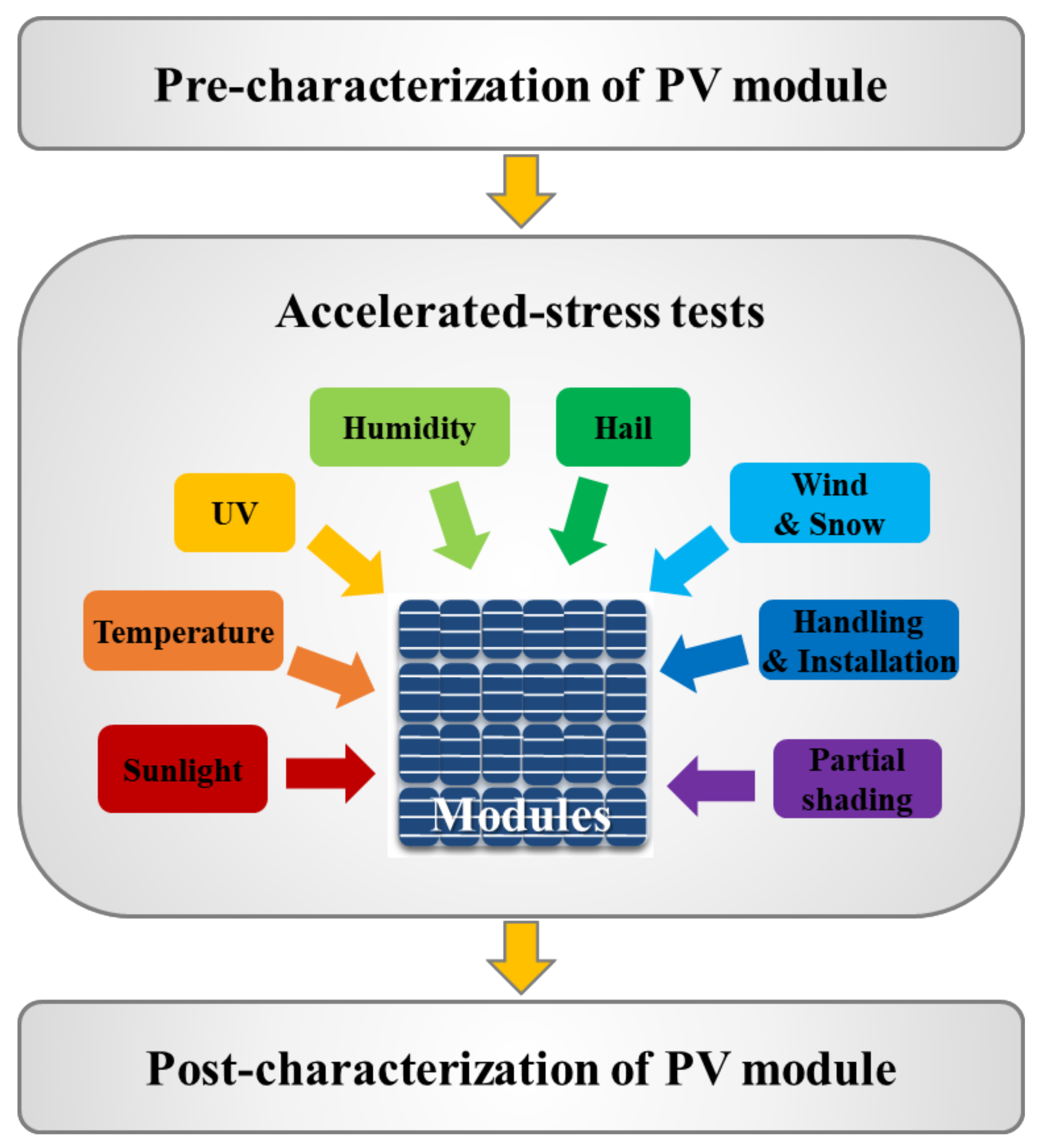
For PV modules, the accelerated aging test is one of the major analyses that the predictive model is based on [28]. The basic concept involves several accelerated-stress tests using pre-characterization and post-characterization techniques. In accelerated-testing (AT) programs, the PV modules undergo different types of stress tests at higher levels than the field-stress levels, in addition to the pre-characterization and post-characterization of materials and modules from durability, reliability, and safety perspectives.
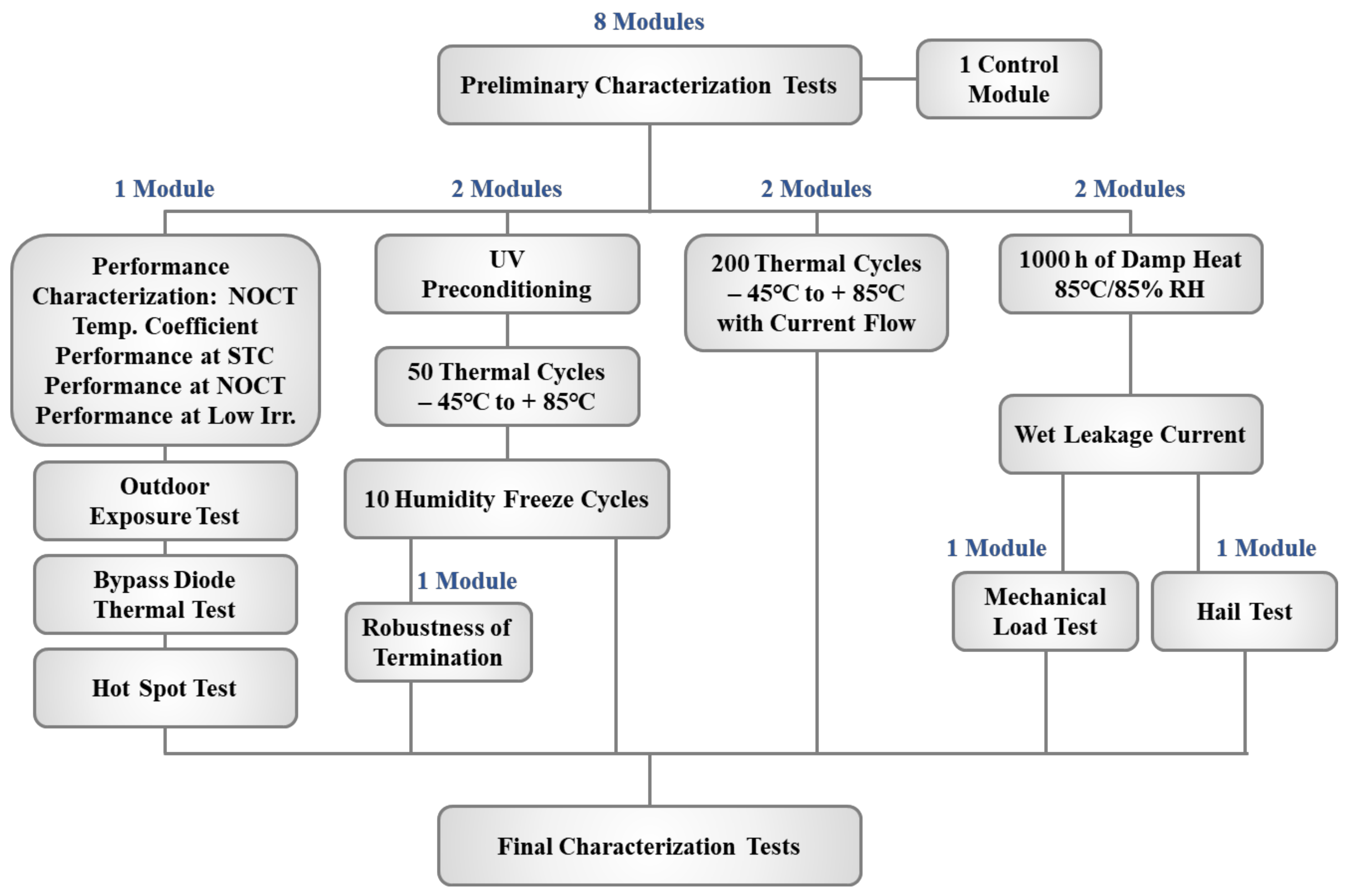
Figure 2 shows the conceptual representation of the AT program on the modules. The developed PV modules should undergo the standard qualification test programs established by the International Electrotechnical Commission (IEC) standards (IEC 61215 for terrestrial photovoltaic modules) and must be developed for comparative and lifetime test programs. In order to understand the testing sequence, the IEC 61215 qualification standard is shown in Figure 3 [29]. In this paper, we discuss different types of degradation, accelerated-stress tests, levels, and prioritization to expand the life expectancy of the PV module by means of IEC 61215.
2. Degradation of a PV Module
Degradation refers to a steady decline in the performance of a constituent [30]. A degraded PV module continues to perform its most important function. It can still produce electricity from sunlight if it is not extensively utilized. Moreover, when the degradation exceeds the critical threshold, the degradation state may cause more problems [31].
As stated by Wohlgemuth et al., industrialists believe that the quality of PV modules will decrease when the energy is less than 80% of the original capacity [32]. The performance of PV modules will reduce as a result of various factors, such as humidity, radiation, temperature, and external impact [33,34]. These factors can cause one or more types of degradation, for example, corrosion, discoloration, delamination, cracking, and breakage [35,36,37]. It is expected that the life expectancy can be predicted by analyzing the degradation modes. The following subsections describe the main degradation modes of silicon solar modules.
2.1. Hot Spots
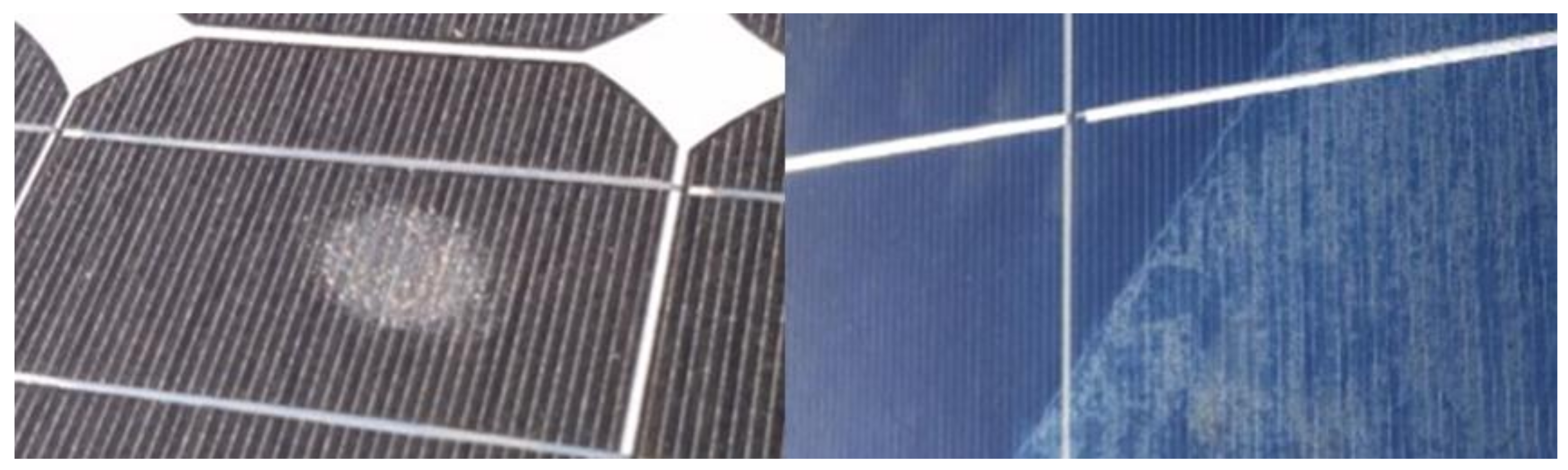
Hot spots are areas of a photovoltaic module with high temperatures that may damage the cells or other parts of the unit, as shown in Figure 4 [38]. The causes of hot spots may be a variety of cellular interferences comprising fractional shadows, cell mismatches, or interrupted connections between cells [39]. In the event of a short circuit, if the PV cell fails, the voltage will reverse and become equal to and opposite to that of the other cells in the series. This faulty solar cell places a burden on the other cells and creates relatively high heat-dissipation positions, thereby forming hot spots [40,41].
2.2. Corrosion of a PV Module
The corrosion of photovoltaic modules is one of the most frequent problems in the field and causes ribbon discoloration [6,42]. Detecting the cause of a PV module’s corrosion might not be straightforward because corrosion mechanisms can be related to other degradation modes [43,44,45,46]. For corrosion to occur in a PV module, an electrolyte, an oxidizing agent, and a metal are required [42].
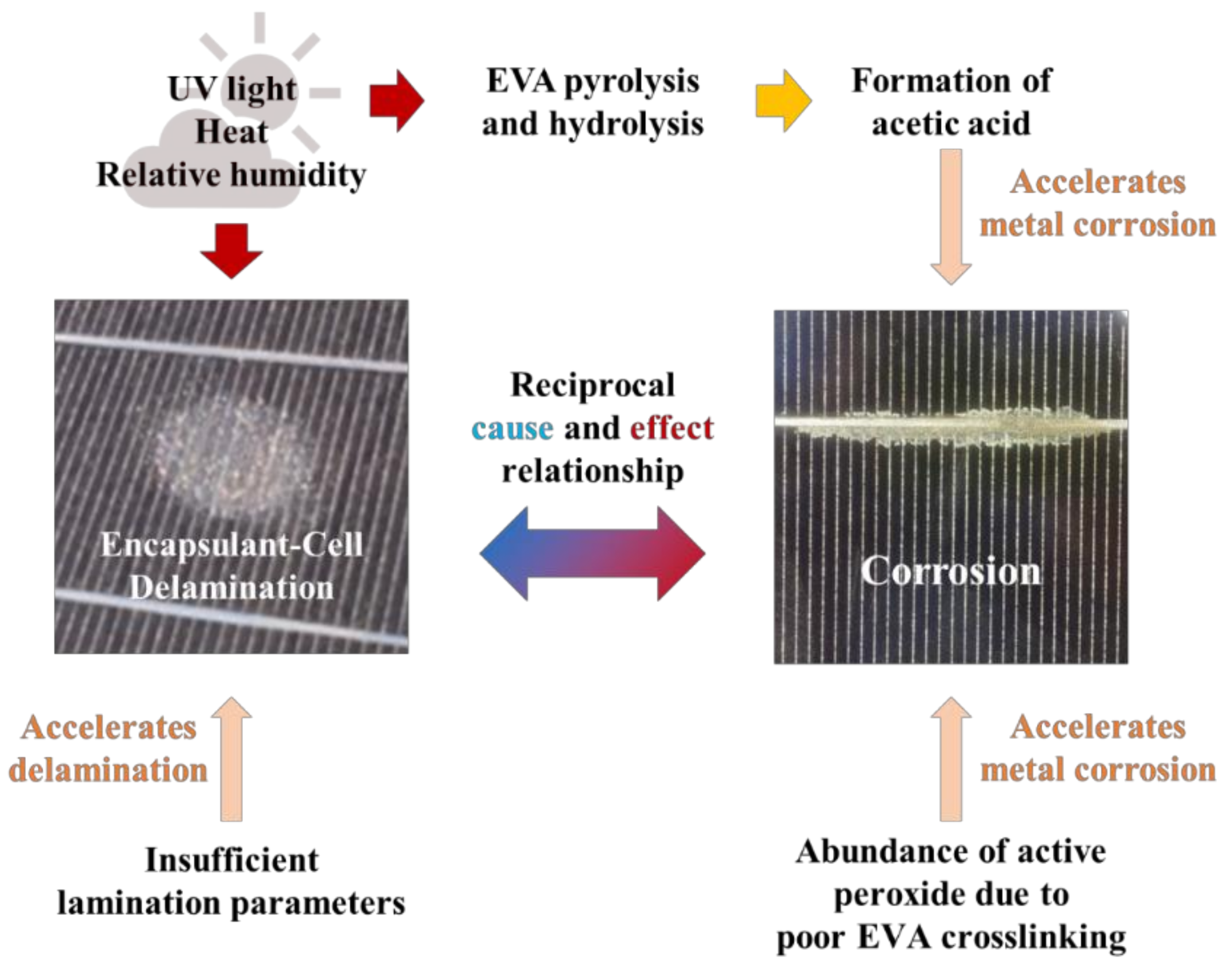
The deterioration of any PV-module component can facilitate corrosion, permitting the penetration of water and oxygen into the solar cell in the PV module. A recent study revealed that the deterioration of the backsheet and encapsulant are the most influential factors related to corrosion [47]. Ethylene vinyl acetate (EVA) deteriorates when the PV module operates under outdoor conditions with UV light, heat, and relative humidity. In the case of a faulty module, the laminated EVA forms acetic acid, which accelerates metal corrosion.
Corrosion in photovoltaic modules is initiated and accelerated by several factors simultaneously and has a reciprocal cause-and-effect relationship [43]. Figure 5 shows a summary of the corrosion mechanisms in PV modules reported in previous studies. They are in agreement regarding the corrosion effect, which is a result of the deterioration of the EVA encapsulant [43,48,49,50]. Some studies have focused on EVA delamination problems caused by insufficient lamination parameters and environmental conditions [43,48]. Others have focused on the formation of acetic acid by using pyrolysis and hydrolysis after moisture and high-temperature exposure [49,50].
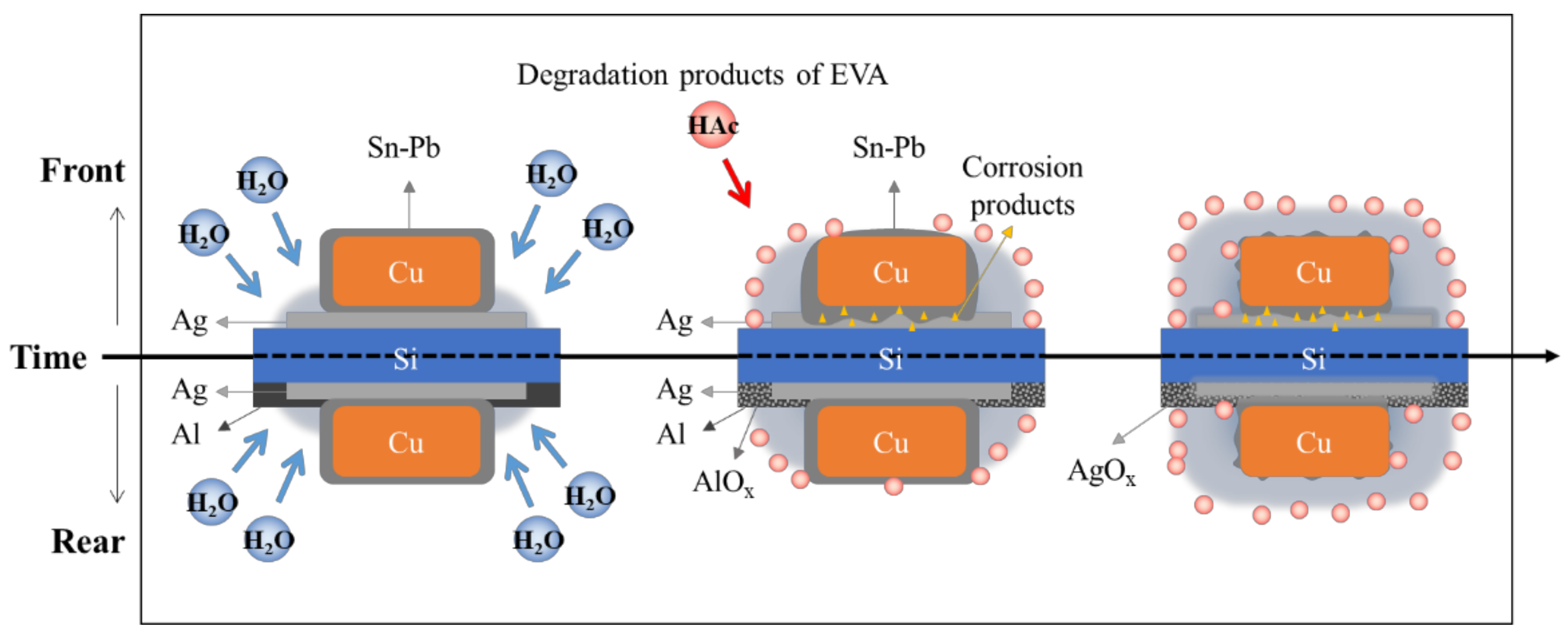
Figure 6 shows the corrosion stages and interactions among the galvanic pairs. Corrosion in PV modules results in a gradual increase in series resistance and power loss. The oxidation potentials of Al/Al(III), Pb/Pb(II), Sn/Sn(II), Cu/Cu(II), and Ag/Ag(I) were −1.662, −0.358, −0.136, 0.337, and 0.799 V, respectively [42,51].
Higher corrosion rates occur in metals with lower oxidation potentials because they act as sacrificial anodes in galvanic couples. On the front side of the solar cell, corrosion begins to occur at the edges of a solder joint upon contact with water. Then, the corrosion will slowly move toward the center, resulting in a decrease in the Ag-solder contact, thus increasing the series resistance [51]. At the rear side, the aluminum contact and solder joint corrode first. As the corrosion progresses and metal is consumed, other metals will also begin to corrode.
2.3. Discoloration of a PV Module
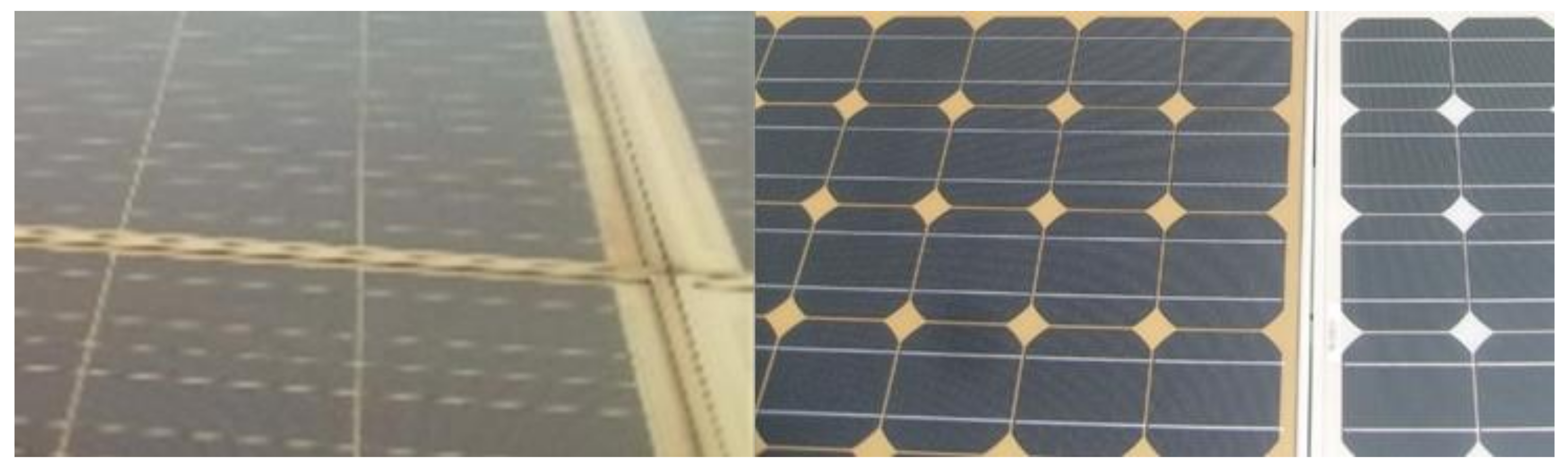
Color changes are typically caused by deprivation in the packaging unit, EVA, or the glue sandwiched between the photovoltaic cells and glass. The EVA changes color from light yellow to dark brown as the discoloration progresses. When solar radiation falls onto a module with a changed cell color, the output power is reduced. Oreski and Wallner pointed out that the chief cause of EVA deprivation is the UV radiation produced by water at temperatures higher than 50 °C [52].
The color change may occur in a different area, rather than next to the PV module. This may mean that the discoloration originates from the polymer of the encapsulation, such as EVA. Moreover, the EVA fails to disseminate in the same method in all cell parts in the same manner [53]. The discolored photovoltaic cells are shown in Figure 7.
Kojima and Yanagisawa studied the yellowness of EVA [54]. In their study, the PV modules were exposed to artificial radiation to evaluate the color of the photovoltaic cells to check the influence of UV light (wavelength range from 280 nm to 380 nm). When an irradiance of 4000 W/m2 was applied, the photovoltaic cell degraded rapidly and decreases in the photosensitivity and transmittance were simultaneously observed.
However, in the UV region from 280 nm to 380 nm, the photosensitivity and transmittance increased after 400 h of exposure. This is mostly due to the reduced UV-radiation absorption that can defend solar cells from color transformation. It accelerates the degradation of the solar module by increasing the absorption of UV light, which is the main cause of degradation. In addition, the browning of the EVA film results in power losses in the PV modules [55]. Osterwald et al. suggested that the less effective and long-lasting deprivation of PV modules possess a linear relationship with the exposure of PV modules to UV radiation [56].
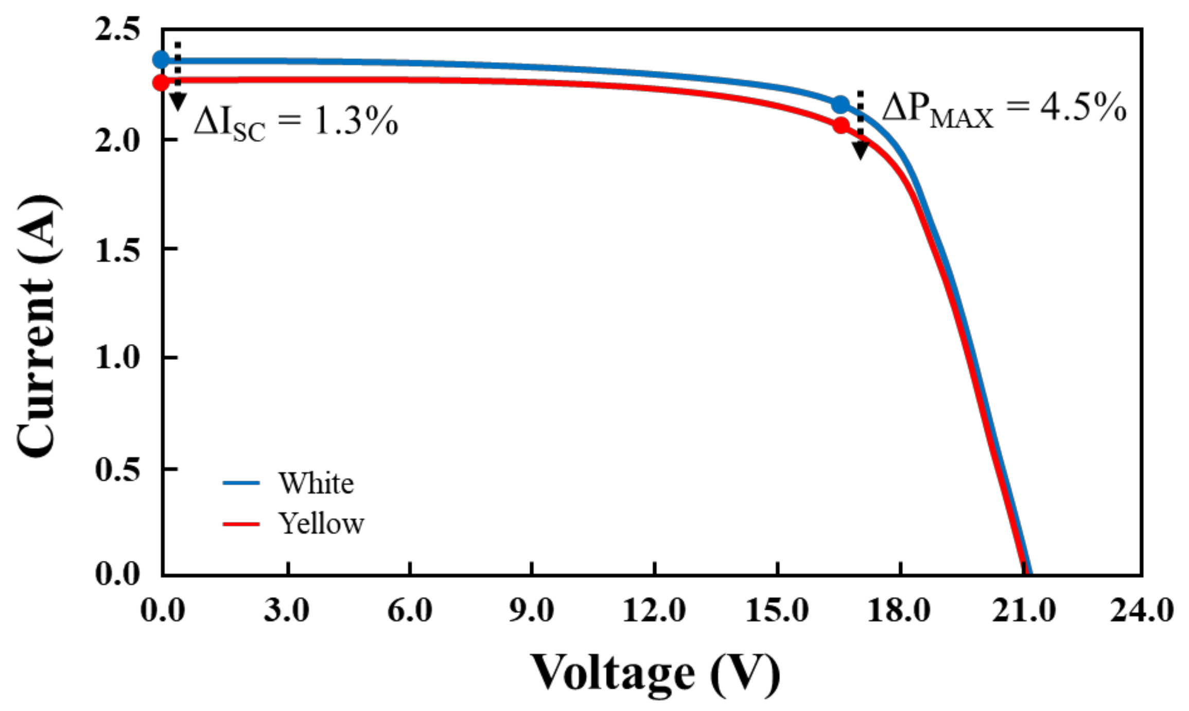
In recent years, most studies on the degradation of crystalline silicon photovoltaic modules have focused on the degradation of EVA [50,57,58]. Realini conducted research between 1982 and 2003, which enabled him to show a relationship between the electric features of the device and the color of the housing [59]. The color change causing partial changes to the surface of the PV module will cause the short-circuit current (Isc) of the PV module to deteriorate. The Isc decomposition range can be lower than the nominal value by 6% to 8% and for complete discoloration, it can range from 10% to 13%. The maximum power (Pmax) of the PV module is correspondingly reduced, owing to the color change of the module, as shown in Figure 8 [59].
2.4. Delamination of a PV Module
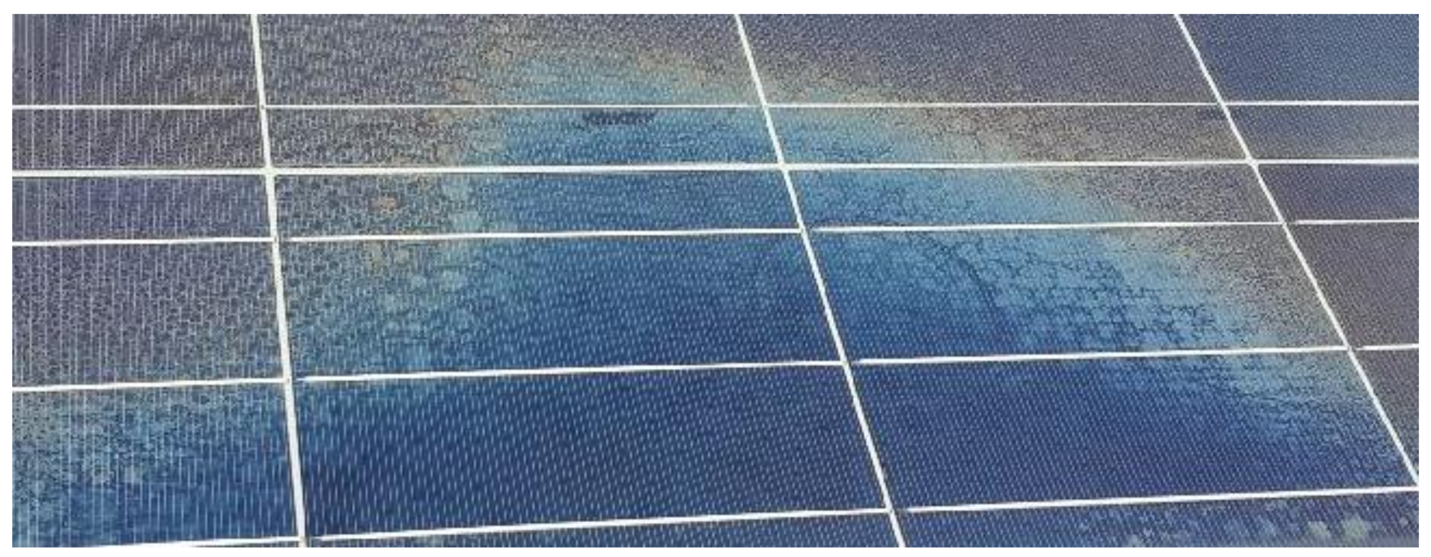
Adhesion loss (termed delamination) occurs between the encapsulation polymer and the solar cell or between the solar cell and the windshield. This is a key problem because it has dual properties: increased sunlit consideration and the diffusion of water into the equipment housing [35,60]. When the discharge occurs at the edge of the device, it will be more serious because it not only reduces the energy consumption but also causes electrical hazards to the device and the entire module.
Spills are more common in warm and humid climates. They allow moisture to enter the equipment and often cause extensive physical and chemical damage, for example, corrosion of metal for the equipment assembly. Figure 9 shows photovoltaic module delamination with a drain flange. Delamination occurs when the EVA loses its adhesive strength under high-humidity and high-temperature conditions, especially around the ribbon [48].
2.5. Cracks and Breakage of PV Modules
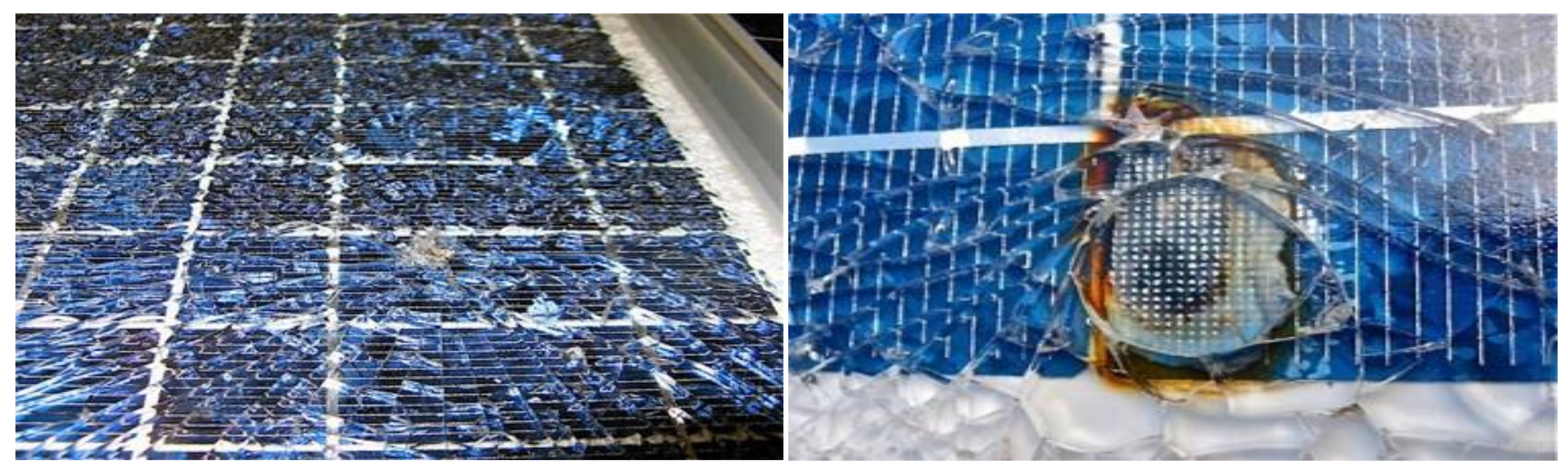
Broken glass significantly degrades photovoltaic modules. Most of the time, this occurs when installing or maintaining the PV module, specifically when transporting the equipment to the installation site [61]. Damaged or broken equipment can still operate normally. A cracked polycrystalline PV module may run for several years while producing significantly less energy, as shown in Figure 10. However, this increases the risk of electric shock and moisture penetration. Fractures and flaws are typically accompanied by different types of degradation, such as wear, color changes, and cracks [33].
In recent years, manufacturers have changed the thickness and area of cells to reduce the amount of silicon and decrease the production cost of solar PV power generation. The thickness of silicon PV cells has been reduced from 300 µm to less than 200 µm and sometimes less than 100 µm. Furthermore, in order to reduce the thickness of the photovoltaic cell, the cell area was also improved to 210 × 210 mm2 [62]. This renders the photovoltaic device more fragile and it breaks faster during management (storing and rolling). In a PV module that is already in operation, it is generally difficult to identify a crack with the naked eye. Such cracks can be detected using optical methods [63].
2.6. PID
In PV systems, PV modules are usually connected in series to increase the voltage of the system output. Therefore, the output voltage of this series circuit can sometimes reach hundreds of volts [64]. In order to protect people from electric shock, the all-metal structures of the equipment are usually grounded. Due to the potential between the photovoltaic module and its structure, when the protection between the structure and the high-voltage layer deteriorates and a leakage current flows, the electrons in the PV module material may escape through the soil structure [65].
Due to this phenomenon, polarization affects the electrical performance of the PV cells. This occurrence is called PID and it is characterized by the gradual degradation of the performance of the crystalline silicon PV module [66,67]. Hack et al. reported that PID is more likely to occur in moist weather than in warm and dry climates [68]. Schütze et al. confirmed this view by proving that the leakage current increases with moisture [64]. In their research, a voltage was applied to the structure of the metal and the contacts of the 60 cell PV module. The applied voltage changed from −600 V at sunrise to 0 V at sunset.
2.7. Bubbles
The bubbles in this type of deprivation are comparable to delaminating; nevertheless, in this situation, the detriment of EVA sticking affects only a minor part and joins with the external part of an expansion that affects the grip. The bubbles are usually the result of a chemical reaction that releases the gas stuck in the PV module. Once this occurs on the rear side of the unit, mobbing occurs in the encapsulated polymer there and causes air bubbles. This renders it harder for solar cells to dissipate heat, resulting in increased temperatures and a shortened life span [67].
Figure 11 shows a photovoltaic module with many bubbles on the back and front. They typically appear at the midpoint or corner of the solar cell and this is possibly because of the poor cell bonds due to the high temperature. Placing a photovoltaic cell in front of the device can reduce the radiation entering the device that separates light and increases its reflection [35].
2.8. Junction Box Failure
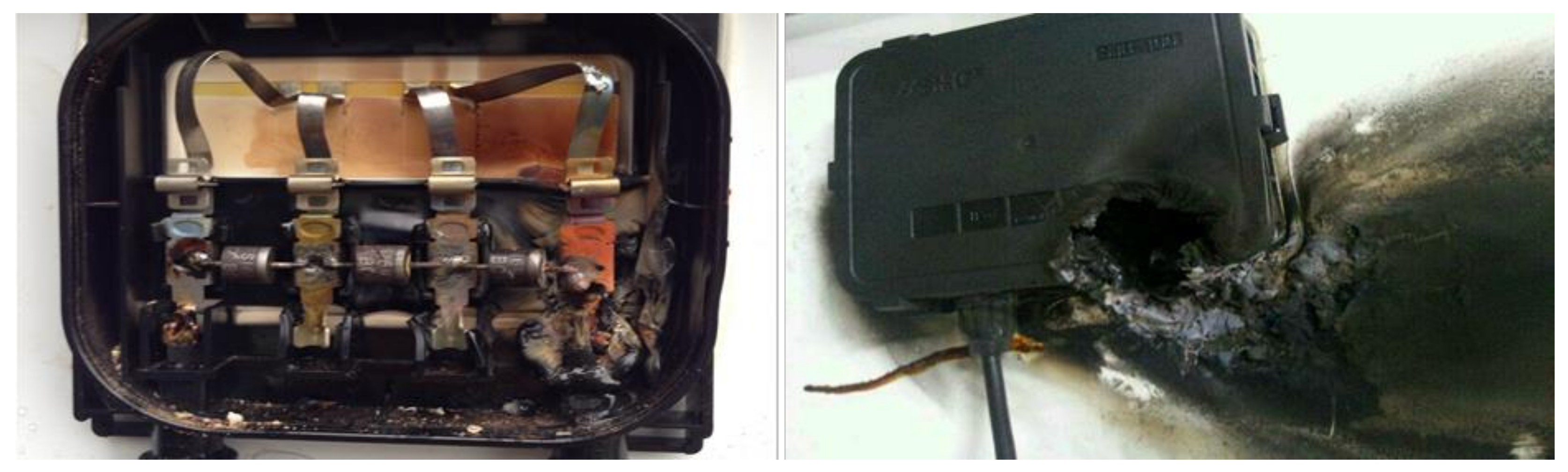
Reliability of the junction box is one of the most important issues for PV modules during a verification testing and operation. In general, about 85% of junction box failures originate from system installation and mostly occur within the first three months of PV system installation [69].
Figure 12 shows the failure of junction boxes. Major failure modes include burned bypass diodes and junction boxes, which in extreme cases increases the risk of fire. Major causes include excessive stress in the system, poor fixing of the junction box to the backsheet, badly closed lid, moisture, and improper wiring [70]. Junction boxes typically contain bypass diodes to protect the cells in case of shadowing or cell problems. However, Zhao Wu et al. confirmed that separating the diode from the junction box can prevent the temperature rise and failure [71].
3. Life Expectancy
3.1. Effect of Different Weather Conditions on the Degradation Rate
It should be noted that the rate of decline of PV power systems in different climatic regions is mainly influenced by cold and hot weather conditions. The results showed that the deprivation rate per year was low in cold places. Larger damage was observed for solar power plants installed in areas with warmer climates, where the deprivation rate per year was high.
Moreover, owing to the rapid changes in ambient temperature and the uneven solar radiation affecting the PV module, it was found that PV systems in hot climates have many defective bypass diodes. However, in cold climates the bypass diodes were not damaged during longer exposure periods. In addition, several cell hot spots were observed in cold-zone areas. Fewer PV modules with hot-spotted PV panels were found in the cold-zone area than compared in the PV systems installed in the hot zone [19,37,72,73].
3.2. Accelerated-Stress Test Types
A reliability test can be accelerated by multiple methods by increasing the level of the experimental variables, such as UV light, humidity, temperature, or voltage. Reliability tests result in certain failure mechanisms in the chemical processes, such as the degradation of chemicals in adhesive bonds or polymeric matrix additives. One or multiple parameters must be measured to better monitor the failure modes. The chosen parameters help to evaluate and identify the constituents of a failure. Accelerated tests are used to induce various types of failure modes in PV modules [61]. Few methods exist for understanding the accelerated indoor aging test for photovoltaic cells and modules by mimicking real field conditions. The following sections briefly discuss these AT methods.
3.2.1. Thermal Cycling
Thermal cycling (TC) is an extensively used profile for determining the evolution of degradation. TC enables the analysis of the PV module’s reliability in manufacturing, construction processes, and estimated field performance. The TC method uses the variation of the temperature between −40 °C and 85 °C and the injected current to imitate constant illumination. The number of cycles varies as a function of the upper limit of the temperature: 500 cycles for 110 °C, 1000 cycles for 85 °C, or 2000 cycles for 65 °C. The injected current in the solar cell is calculated as 1.25 × Isc × the number of suns, where Isc represents the short-circuit current [74]. Although many reports have been presented on the degradation of PV modules caused by temperature and corrosion [75,76,77], the phenomenon requires more attention and further work to understand and explain these aging factors.
A study by Khan et al. [78] explains the failure and degradation behavior of a c-Si PV module installed over a concrete slab that occurred during a TC stress test. A connection between the TC duration and the device was established. In this study, the authors used monocrystalline PV modules with an area of 1540 cm2 and a rigid module (fixed on a concrete slab) consisted of 36 cells with an Al frame (cell area = 31.2 cm2). The ability of the module to withstand fatigue, thermal mismatch, and other stresses caused by temperature fluctuations was evaluated for 200 thermal cycles in a climate chamber. Figure 13 depicts the measurement of the I-V characteristics for both PV modules before and after TC (100 and 200) and a clear sign of an increase in the series resistance. The power losses after 200 thermal cycles were approximately 3% and 4% in the cases without and with concrete, respectively. This is mainly related to the thermal exhaustion of the PV module.
3.2.2. Damp Heat
The reliability and long-term durability of a PV module are associated with the durability of the encapsulant and its interface with the glass and back sheet [47,79]. Humidity has the potential to degrade many electronic products, along with the PV module. Therefore, moisture penetration into the PV-module package can possibly generate corrosion and adhesion loss between the layers. The acceleration of the moisture ingress can be simulated by a damp-heat test with an elevated temperature and high humidity. According to the IEC 61215 standard, 1000 h of damp heat, 10 cycles of humidity freezing, and 200 cycles of TC are the common specifications used to screen PV modules in the industry [80,81].
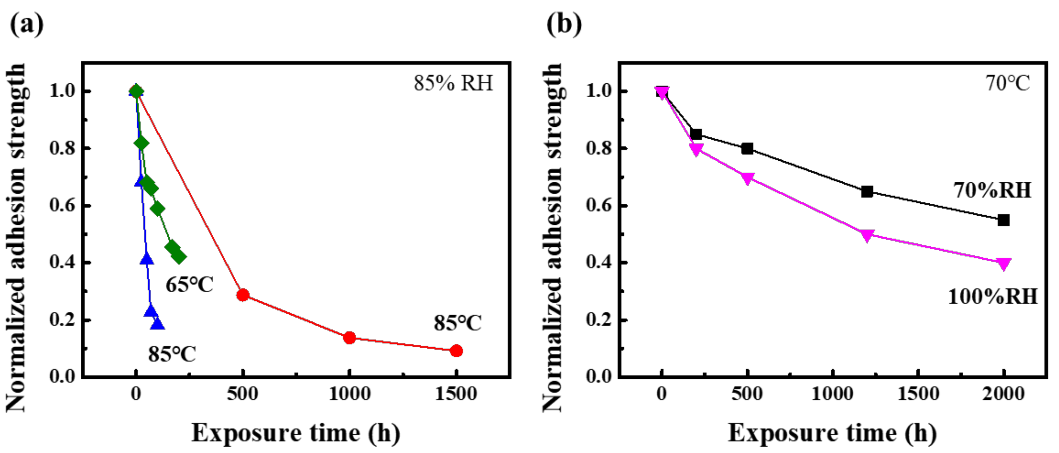
The degradation of the adhesion strength of the glass-encapsulant interface after damp-heat tests is shown in Figure 14 with variations in temperature and relative humidity [82,83,84]. When comparing Figure 14a,b, which possess the same conditions of 85 °C/85% relative humidity (RH), the difference in the degradation rate is due to the difference in the initial adhesive strength. The adhesive strength shown in Figure 14a, which is initially low and decreases rapidly, even in a small amount of time. The adhesive strength shown in Figure 14b, which is initially large, decreases relatively slowly. It can be observed that the degradation is affected by both temperature and humidity, as the degradation is accelerated both when only the temperature is high and when only the humidity is high.
3.2.3. Ultraviolet (UV) Light Exposure
Another important variable in the accelerated-stress test for the PV module is UV-light exposure because it degrades some of the polymers and adhesives. The backsheet and encapsulant of the PV module degrade in UV light with discoloration to yellow, called yellowing or browning. During the accelerated UV test, it is important to consider that the selection of a high temperature can always accelerate the UV-induced damage and to observe whether a reciprocal relationship exists between the exposure duration and light intensity.
In recent studies, floating PV systems have become more attractive owing to their cost effectiveness and operation in higher humidity environments because of their installation in reservoirs and ponds [85]. As a higher amount of UV light is reflected from the water surface, it is an important stress factor [86] to consider and a different acceleration test is required to improve the durability according to various field conditions.
During a UV exposure test, the exposure levels should be maintained at similar irradiation levels to experience field results close to the actual outdoor exposures. The time lapse between the UV exposure of the actual field and accelerated-test field differs because it has four to six equivalent sun hours per day. The constant UV exposure may provide an acceleration factor of four to six times. In order to simulate the same degradation mechanisms, long-term UV exposure requires a very long test time. In order to effectively reproduce the degradation mechanism, some studies have proposed a technique of combining different accelerated-test variables into a single test or sequential testing [87].
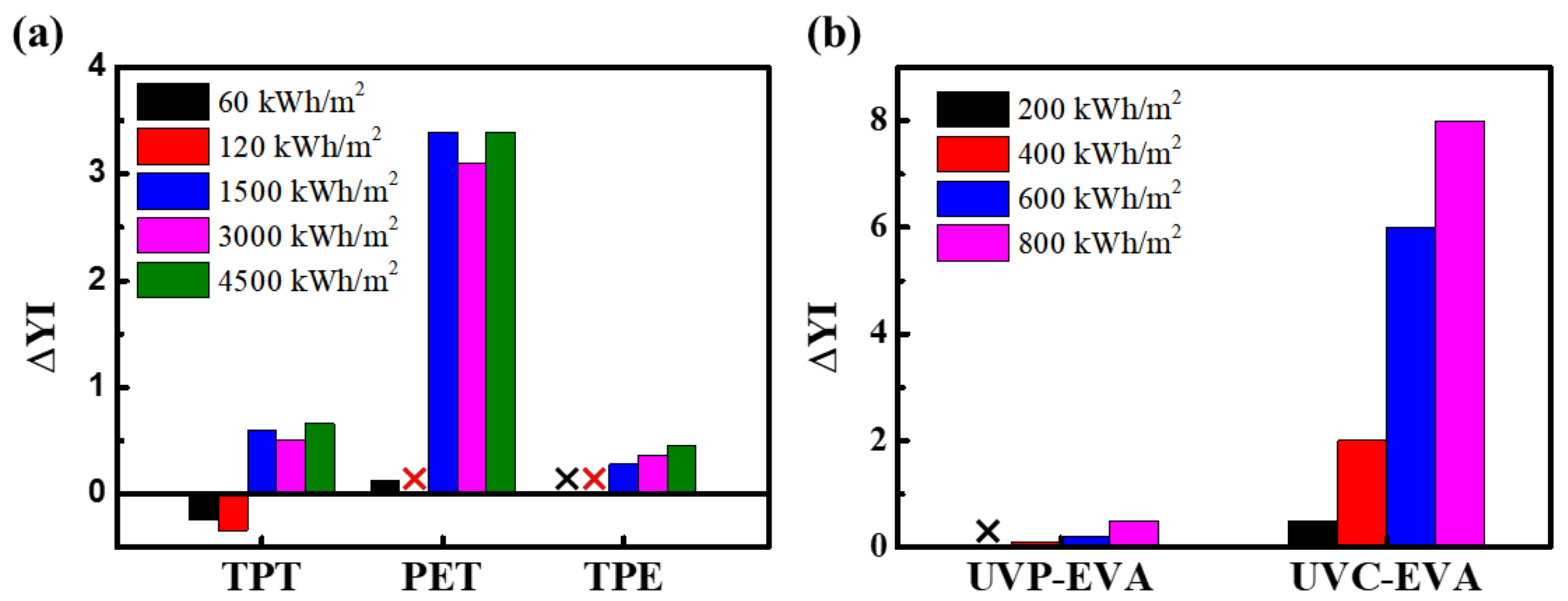
The accelerated UV test changed the appearance and yellowness index (YI), as shown in Figure 15 [88,89,90]. The backsheets consisted of three different polymers, namely polyvinyl fluoride (PVF), polyethylene terephthalate (PET), and EVA. It is shown that PET is the most vulnerable to UV among the different types of backsheets: TPT (PVF/PET/PVF), PET (PVF/PET/Tie layer), and TPE (PVF/PET/EVA).
The YI change for EVA, which is the most used material for encapsulants, is shown in Figure 15b. A comparison and analysis were conducted on UV-pass (UVP) EVA and UV-cut (UVC) EVA and the UVC-EVA showed remarkably high discoloration. This material is designed to absorb the UV light into the EVA to block it from the PV module; thus, it has a greater degradation because of the large amount of UV absorption. It can be observed that the greater the UV dose, the greater the discoloration.
3.2.4. Static and Dynamic Mechanical Loads
The mechanical-load test is a standard qualification-test protocol for PV-module products. The test was performed by simulating wind and snow as a combined static load. The outdoor field operation, handling, and transportation of PV modules are not necessarily static conditions. One must understand the effects of both static and dynamic-load tests and analyze their interactions with climatic conditions.
Each new type of module must undergo a series of stress tests, such as climatic, electrical, and mechanical. The standard protocol of IEC 61215 is well established and accepted in the PV industry [91]. Before installation, the modules experience mechanical stress during transportation, including vibrations and shocks [92]. After PV-module installation, the PV module is exposed to static stress by means of snow and dynamic stress by wind [93]. The reliability of the PV module with respect to wind and snow loads can be observed in the static mechanical-loading (SML) test standards. The test consisted of a static load of 2400 Pa with 3 × 2 h cycles to the back and then to the front. For the heavy load test, a load of 5400 Pa was applied to the front side at the end of the last cycle.
The American IEEE 1262 standard proposed an additional test as a dynamic mechanical-loading (DML) [94] test with 10,000 cycles at 1440 Pa for at least 3 s/cycle. The fracture mechanism of silicon shows the propagation of microcracks and/or cell breakage depending on the maximum bending radius of the module. The dynamic-load test is a superior. method for detecting a fault from bad soldering than the static-load test. An increase in the number of cycles in the dynamic load results in a weakening of the solder joints and/or copper ribbons.
With the static mechanical load, microcracks and broken cells can be detected efficiently with electroluminescence because of the higher pressure in the standard SML. DML tests affect the mechanical robustness of the solder contacts in PV modules. BP Solar reported a strong power loss after combining the dynamic-load test with climatic stress on PV modules with cracks, but not in the static-load test [95].
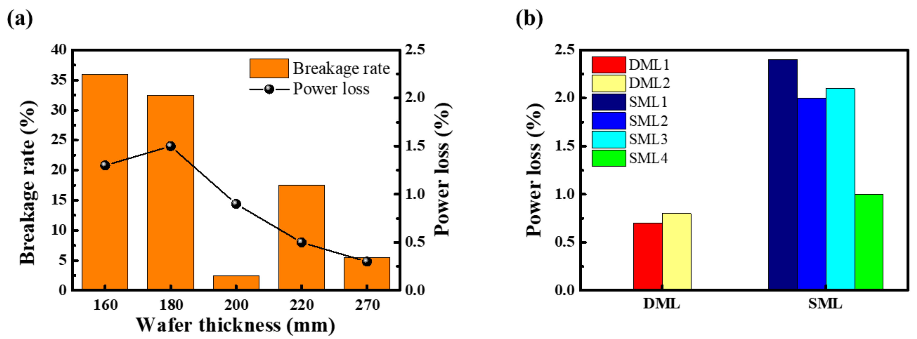
Analyzing the breakage rate and power loss according to the thickness of the wafer revealed that both the breakage rate and the power loss increased as the thickness decreased after DML tests [96]. Figure 16b shows the power loss of the module before and after SML and DML tests. The power losses are slightly higher in the static-load modules than in the surviving dynamic-load modules [97].
3.2.5. Reverse-Bias Hot-Spot Test and Bypass-Diode Thermal Test
Another important aspect affecting the reliability of PV power generators is hot-spot failures. The hot-spot failure of a PV module is mainly due to a power mismatch in some cells in the PV module; it operates in a reverse bias as a load by the power-generating unit. It consumes energy and generates considerable heat, which may cause a fire in serious cases and result in safety issues in large-scale PV power stations [98,99,100].
It is important to study and analyze hot-spot failures in detail before they affect the entire system. Several studies are available on treating hot-spot faults, including infrared (IR) thermal imaging. IR thermal imaging can determine the hot-spot module and the distribution of the hot spot by showing the color difference between the heat-generating cell and a standard cell with an infrared camera [101]. This process is quite expensive, requires high precession, and possesses poor autonomy. Along with the IR-imaging method, another technique is to determine the electrical characteristics of the module where the hot spot occurs [102,103].
In diagnosing a hot-spot cell, one must shade a cell in the module and observe the rate of current change in a particular voltage range of the I-V curve [104]. This study is valid only for cells that have a large reverse-leakage current and the diagnosis process is weightier. Another method of diagnosing a hot-spot module is to inject an AC signal into the PV module and analyze the difference in the impedance spectrum [105].
In a recent study, Ma et al. diagnosed hot-spot faults using the I-V curve of the PV module with a distance calculation between the scan point and the lines produced by the points [106]. By using this method, various types of I-V curves can be quickly examined to diagnose hot-spot faults. The effect of this method was evaluated using PV power-station field data.
In order to decrease the reverse-bias voltage on shadowed or current-limiting cells, bypass diodes can be programmed to switch on automatically in the presence of any current mismatches [107]. Recurring hot-spot events may result in accelerated aging and, thus, increases the probability of a fault [108]. Hot-spot occurrences can be avoided by using a bypass diode; however, it can limit the power dissipation [109].
Bypass diodes have a basic feature that is fully suited for the normal operation of a PV module as they automatically activate themselves only when needed. In the case of any mismatch, the bypass diode switches ON because of the control algorithms (maximum power point tracking). This algorithm can lower the current delivered by the PV system by placing the diode in the ON position, which allows the system to operate in a safe region [110]. Thus, their approach has achieved some success in limiting hot spots.
3.2.6. Hail Test
Hail is another main reason why a PV module loses its reliability. Analytical and experimental studies should be performed to estimate the impact of hail on PV modules. Generally, two types of PV modules are used [111]: (1) A rigid plate with a glass layer on the outside that protects the module from mechanical loads and (2) semi-flexible plates with a protective polymer that must be fixed to flat or curved surfaces. PV modules operate in outdoor conditions, such as thermo-hygrometric cycles; snow, wind, and hail are the main sources of PV-module damage and degradation before its lifetime.
The hail test is carried out using pneumatic equipment to observe the current losses from the I-V; it can obtain clear visual pictures of the microcracks from the electroluminescence and their effect on the electrical response [112,113]. The IEC 61215 standard must be met by all newly manufactured PV modules in Europe, regardless of the type or materials [82]. As per IEC 61215, hail-impact simulation tests must be performed by firing a formed ice ball at a PV module with pneumatic actuators. The ice ball parameters for the hail test are a diameter of 25 mm and an impact velocity of 23 m/s [114]. Moreover, the repeatability of the tests is important during the test process.
Kilikeviciene et al. studied a hail-simulation testbed to identify the conditions required for hail simulation and analyzed the performance parameters before and after the dynamic impact on the PV modules. The tests revealed that the PV modules suffered from severe damage and microcracks in the crystalline solar cell when exposed to the force. Increasing the force-impacting test resulted in an increase in the PV-module power loss of up to 8.29% [115].
4. Solutions to Minimize the Degradation Rate
Corrosion can be managed by numerous measures such as coatings, corrosion inhibitors, and material selection while highly prominent tools for restraint against corrosion are being deliberated. These are constituents that, when placed in this situation, minimizes the scale of corrosion to the atmosphere and are more resistant to deterioration. Therefore, employing these resources will enhance the working period of the solar cells [116]. The corrosion of the PV system will be controlled by eradicating corrosion from internal and external components.
Subsequent techniques can also be applied to reduce the corrosion rate; for example, EVA provides PV cells with isolation from the flow of electrons, structural strength, and protection from dangerous and critical atmospheric conditions [117]. EVA is a polymer that can defend the external face by substantially avoiding water accumulation at its joining parts. Stainless steel or other corrosion-resistant alloys can be used in PV cells because of their high corrosion prevention; thus, the frames of solar modules can be manufactured from these materials [118].
Other solutions for minimizing PV-module degradation have been proposed. Incorporating nanomaterials into solar panels can not only improve the mechanical properties of polymers, but also impart other functions with high resistance to water vapor and corrosive gases [119]. For the long-lasting constancy of solar cells, plasma activation can be used to build weather-resistant solar modules using a strong binder that is highly reliable and waterproof [120]. A windshield made of low-iron glass transmits UV (no cerium oxide) light and is large enough to limit oxygen. It is very important for PV-module manufacturers to observe the performance of their products in the field [121].
Solutions to reduce the propensity of crack propagation or the impact of open cracks on module operation are at the solar, module, and system levels. However, certain results have been achieved with progressive cell construction. Cracking at the cell level can be minimized by utilizing the following solutions: thicker wafers, multiple busbar/interconnect wires, wires closer to the cell edge, rectangular or half-cut cells, uniform power loss, and reverse “breakdown” at low voltages. In addition, the cracks at the module level can be reduced by deploying the following methods: optimized soldering materials, equipment and quality control, glass-module construction, solder with more flexible materials, and a greater number of bypass diodes [122].
5. Conclusions
In this article, we reviewed various modes of PV-module degradation rates and AT methods for life expectancy. Corrosion, discoloration, deformation, destruction, delamination, breakage, and cracking are the main causes of solar-module deprivation. Environmental factors, such as temperature, humidity, and UV radiation, are the main factors affecting the aging of PV modules.
Concerns about a PV module’s performance drift (durability) or premature outdating (reliability) are major obstacles to PV deployment and project financing. AT is a method of evaluating the reliability and durability of PV modules by encouraging failures and performance degradation in a short time period. AT uses more severe operating conditions than the original field operating conditions to replicate the actual field-failure mechanisms.
The current review provided detailed observations of the current and future states of PV-module AT. According to the literature, there is a significant need to improve the accelerated-test protocol for relative and lifetime testing of PV modules. Accelerated-test conditions focus on analyzing the PV-module health and technical failures after selecting a specific test corresponding to a specific failure mode and applying the test.
Research on AT to date has suggested and successfully mitigated the different types of failure and degradation modes that occur in PV modules under real-time working conditions. The failure and degradation modes of PV modules are largely determined by the actual field work conditions in which they are configured and operated.
Accelerated tests have been successful to some extent; however, a vast database of climatic conditions should be created, especially by comparing old PV power plants (10–30 years) with the same characteristics as the current-generation modules. This will help develop a variety of accelerated tests that are prioritized by specific climatic conditions. We also offer some solutions to minimize solar-cell deterioration in Section 4, which can help manufacturers optimize their production to improve cell quality and provide long-term warranties to customers.
Author Contributions
Conceptualization, E.-C.C. and J.Y.; methodology, E.-C.C.; software, M.R.; validation, E.-C.C. and J.Y.; formal analysis, J.K.; investigation, S.P.P.; resources, H.Y.; data curation, J.K.; writing—original draft preparation, J.K.; writing—review and editing, J.K.; visualization, J.K.; supervision, E.-C.C.; project administration, J.Y.; funding acquisition, E.-C.C. and J.Y. All authors have read and agreed to the published version of the manuscript.
Funding
This research received no external funding.
Institutional Review Board Statement
Not applicable.
Informed Consent Statement
Not applicable.
Data Availability Statement
Not applicable.
Acknowledgments
This research was supported by the Korea Electric Power Corporation (Project No. R21XO01-22) and grants from the New and Renewable Energy Technology Development Program of the Korea Institute of Energy Technology Evaluation and Planning (KETEP), which are funded by the Korean Ministry of Trade, Industry, and Energy (MOTIE) (20203030010060).
Conflicts of Interest
The authors declare no conflict of interest.
References
- Renewables 2020. International Energy Agency. 2020. Available online: https://www.iea.org/reports/renewables-2020 (accessed on 24 December 2020).
- Tsanakas, J.A.; Ha, L.; Buerhop, C. Faults and infrared thermographic diagnosis in operating c-Si photovoltaic modules: A review of research and future challenges. Renew. Sustain. Energy Rev. 2016, 62, 695–709. [Google Scholar] [CrossRef]
- Virtuani, A.; Caccivio, M.; Annigoni, E.; Friesen, G.; Chianese, D.; Ballif, C.; Sample, T. 35 years of photovoltaics: Analysis of the TISO-10-kW solar plant, lessons learnt in safety and performance—Part 1. Prog. Photovolt. Res. Appl. 2019, 27, 328–339. [Google Scholar] [CrossRef]
- Da Fonseca, J.E.F.; de Oliveira, F.S.; Prieb, C.W.M.; Krenzinger, A. Degradation analysis of a photovoltaic generator after operating for 15 years in southern Brazil. Sol. Energy 2020, 196, 196–206. [Google Scholar] [CrossRef]
- Ishii, T.; Masuda, A. Annual degradation rates of recent crystalline silicon photovoltaic modules. Prog. Photovolt. Res. Appl. 2017, 25, 953–967. [Google Scholar] [CrossRef]
- Jordan, D.C.; Silverman, T.J.; Wohlgemuth, J.H.; Kurtz, S.R.; VanSant, K.T. Photovoltaic failure and degradation modes. Prog. Photovolt Res. Appl. 2017, 25, 318–326. [Google Scholar] [CrossRef]
- Martín-Martínez, S.; Cañas-Carretón, M.; Honrubia-Escribano, A.; Gómez-Lázaro, E.J.E.C. Performance evaluation of large solar photovoltaic power plants in Spain. Energy Convers. Manag. 2019, 183, 515–528. [Google Scholar] [CrossRef]
- Lovati, M.; Salvalai, G.; Fratus, G.; Maturi, L.; Albatici, R.; Moser, D. New method for the early design of BIPV with electric storage: A case study in northern Italy. Sustain. Cities Soc. 2019, 48, 101400. [Google Scholar] [CrossRef] [Green Version]
- Singh, R.; Sharma, M.; Rawat, R.; Banerjee, C. Field Analysis of three different silicon-based Technologies in Composite Climate Condition–Part II–Seasonal assessment and performance degradation rates using statistical tools. Renew. Energy 2020, 147, 2102–2117. [Google Scholar] [CrossRef]
- Gaglia, A.G.; Lykoudis, S.; Argiriou, A.A.; Balaras, C.A.; Dialynas, E. Energy efficiency of PV panels under real outdoor conditions–An experimental assessment in Athens, Greece. Renew. Energy 2017, 101, 236–243. [Google Scholar] [CrossRef]
- Jurasz, J.K.; Dąbek, P.B.; Campana, P.E. Can a city reach energy self-sufficiency by means of rooftop photovoltaics Case study from Poland. J. Clean. Prod. 2020, 245, 118813. [Google Scholar] [CrossRef]
- Chandel, S.S.; Naik, M.N.; Sharma, V.; Chandel, R. Degradation analysis of 28 year field exposed mono-c-Si photovoltaic modules of a direct coupled solar water pumping system in western Himalayan region of India. Renew. Energy 2015, 78, 193–202. [Google Scholar] [CrossRef]
- Thotakura, S.; Kondamudi, S.C.; Xavier, J.F.; Quanjin, M.; Reddy, G.R.; Gangwar, P.; Davuluri, S.L. Operational performance of megawatt-scale grid integrated rooftop solar PV system in tropical wet and dry climates of India. Case Stud. Therm. Eng. 2020, 18, 100602. [Google Scholar] [CrossRef]
- Tongsopit, S.; Junlakarn, S.; Wibulpolprasert, W.; Chaianong, A.; Kokchang, P.; Hoang, N.V. The economics of solar PV self-consumption in Thailand. Renew. Energy 2019, 138, 395–408. [Google Scholar] [CrossRef]
- Dechthummarong, C.; Wiengmoon, B.; Chenvidhya, D.; Jivacate, C.; Kirtikara, K. Physical deterioration of encapsulation and electrical insulation properties of PV modules after long-term operation in Thailand. Sol. Energy Mater. Sol. Cells 2010, 94, 1437–1440. [Google Scholar] [CrossRef]
- Park, J.H.; Lee, H.D.; Tae, D.H.; Ferreira, M.; Rho, D.S. A Study on Disposal Diagnosis Algorithm of PV Modules Considering Performance Degradation Rate. J. Korea Acad. Ind. Coop. Soc. 2019, 20, 493–502. [Google Scholar]
- Teah, H.S.; Yang, Q.; Onuki, M.; Teah, H.Y. Incorporating External Effects into Project Sustainability Assessments: The Case of a Green Campus Initiative Based on a Solar PV System. Sustainability 2019, 11, 5786. [Google Scholar] [CrossRef] [Green Version]
- Jordan, D.C.; Deline, C.; Deceglie, M.; Silverman, T.J.; Luo, W. PV Degradation–Mounting & Temperature. In Proceedings of the 2019 IEEE 46th Photovoltaic Specialists Conference (PVSC), Chicago, IL, USA, 16–21 June 2019; pp. 673–679. [Google Scholar]
- Dhimish, M.; Alrashidi, A. Photovoltaic Degradation Rate Affected by Different Weather Conditions: A Case Study Based on PV Systems in the UK and Australia. Electronics 2020, 9, 650. [Google Scholar] [CrossRef] [Green Version]
- Jordan, D.C.; Wohlgemuth, J.H.; Kurtz, S.R. Technology and climate trends in pv module degradation. In Proceedings of the 27th European Photovoltaic Solar Energy Conference and Exhibition, Frankfurt, Germany, 24–28 September 2012. [Google Scholar]
- Herrmann, W.; Bogdanski, N.; Reil, F.; Köhl, M.; Weiss, K.-A.; Assmus, M.; Heck, M. PV module degradation caused by thermomechanical stress: Real impacts of outdoor weathering versus accelerated testing in the laboratory. In Reliability of Photovoltaic Cells, Modules, Components, and Systems III; International Society for Optics and Photonics: Bellingham, DC, USA, 2010; Volume 7773, p. 77730I. [Google Scholar]
- John, H.W. Photovoltaic Module Reliability; Wiley: Hoboken, NY, USA, 2020. [Google Scholar]
- Bouguerra, S.; Yaiche, M.R.; Gassab, O.; Sangwongwanich, A.; Blaabjerg, F. The Impact of PV Panel Positioning and Degradation on the PV Inverter Lifetime and Reliability. IEEE J. Emerg. Sel. Top. Power Electron. 2021, 9, 3114–3126. [Google Scholar] [CrossRef]
- Majumdar, D.; Pal, S.B.; Ganguly, R. Comparative Reliability Analysis of PV Modules under tropical conditions. In Proceedings of the Innovations in Energy Management and Renewable Resources (52042), Kolkata, India, 5–7 February 2021; pp. 1–5. [Google Scholar]
- Yan, W.; Liu, W.; Kong, W. Reliability evaluation of PV modules based on exponential dispersion process. Energy Rep. 2021, 7, 3023. [Google Scholar] [CrossRef]
- Muller, M.; Repins, I. Proceedings of the PV Reliability Workshop. 22–26 February 2021. Available online: https://www.nrel.gov/docs/fy21osti/80055.pdf (accessed on 26 February 2021).
- Kurtz, S. Reliability and Durability of PV Modules. In Photovoltaic Solar Energy; John Wiley & Sons, Ltd.: Hoboken, NJ, USA, 2017; pp. 491–501. [Google Scholar]
- Jordan, D.C.; Kurtz, S.R. Photovoltaic Degradation Rates-an Analytical Review. Prog. Photovolt. Res. Appl. 2013, 21, 12–29. [Google Scholar] [CrossRef] [Green Version]
- Wohlgemuth, J. Tutorial/short course on reliability: PV cells, modules, and systems. In Proceedings of the IEEE Photovoltaic Specialists Conference, Seattle, WA, USA, 19–24 June 2011. [Google Scholar]
- Lannoy, A.; Procaccia, H. Evaluation et Maîtrise du Vieillissement Industriel; Lavoisier: Paris, France, 2005. [Google Scholar]
- Charki, A.; Laronde, R.; Bigaud, D. The time-variant degradation of a photovoltaic system. J. Sol. Energy Eng. 2013, 135, 024503. [Google Scholar] [CrossRef]
- Wohlgemuth, J.H.; Cunningham, D.W.; Monus, P.; Miller, J.; Nguyen, A. Long term reliability of photovoltaic modules. In Proceedings of the 2006 IEEE 4th World Conference on Photovoltaic Energy Conference, Waikoloa, HI, USA, 7–12 May 2006; pp. 2050–2053. [Google Scholar]
- Quintana, M.A.; King, D.L.; McMahon, T.J.; Osterwald, C.R. Commonly observed degradation in field-aged photovoltaic module. In Proceedings of the Conference Record of the Twenty-Ninth IEEE Photovoltaic Specialists Conference, New Orleans, LA, USA, 19–24 May 2002; pp. 1436–1439. [Google Scholar]
- Osterwald, C.R.; McMahon, T.J. History of accelerated and qualification testing of terrestrial photovoltaic modules: A literature review. Prog. Photovolt. Res. Appl. 2009, 17, 11–33. [Google Scholar] [CrossRef]
- Munoz, M.A.; Alonso-García, M.C.; Vela, N.; Chenlo, F. Early degradation of silicon PV modules and guaranty conditions. Sol. Energy 2011, 85, 2264–2274. [Google Scholar] [CrossRef]
- Vázquez, M.; Rey-Stolle, I. Photovoltaic module reliability model based on field degradation studies. Prog. Photovolt. Res. Appl. 2008, 16, 419–433. [Google Scholar] [CrossRef] [Green Version]
- Chowdhury, S.; Cho, E.C.; Cho, Y.; Kim, Y.; Yi, J. Analysis of Cell to Module Loss Factor for Shingled PV Module. KSNRE 2020, 16, 1–12. [Google Scholar] [CrossRef]
- Dhimish, M.; Holmes, V.; Mehrdadi, B.; Dales, M.; Mather, P. Output-power enhancement for hot spotted polycrystalline photovoltaic solar cells. Trans. Device Mater. Reliab. 2017, 18, 37–45. [Google Scholar] [CrossRef]
- Molenbroek, E.; Waddington, D.W.; Emery, K.A. Hot spot susceptibility and testing of PV modules. In Proceedings of the 22th IEEE Photovoltaic Specialists Conference (Las Vegas), Las Vegas, NV, USA, 7–11 October 1991; pp. 547–552. [Google Scholar]
- Cox III, C.H.; Silversmith, D.J.; Mountain, R.W. Reduction of photovoltaic cell reverse breakdown by a peripheral bypass diode. In Proceedings of the 16 IEEE Photovoltaics Specialists Conference, San Diego, CA, USA, 28 September 1982. [Google Scholar]
- Rauschenbach, H.S.; Maiden, E.E. Breakdown phenomena in reverse biased silicon solar cells. In Proceedings of the Record of the 9th IEEE Photovoltaic Specialists Conference, Silver Spring, MD, USA, 19–24 May 2002. [Google Scholar]
- Kim, J.-H.; Park, J.; Kim, D.; Park, N. Study on Mitigation Method of Solder Corrosion for Crystalline Silicon Photovoltaic Modules. Int. J. Photoenergy 2014, 2014, 809075. [Google Scholar] [CrossRef]
- Li, J.; Shen, Y.-C.; Hacke, P.; Kempe, M. Electrochemical mechanisms of leakage-current-enhanced delamination and corrosion in Si photovoltaic modules. Sol. Energy Mater. Sol. Cells 2018, 188, 273–279. [Google Scholar] [CrossRef]
- Oreski, G.; Rauschenbach, A.; Hirschl, C.; Kraft, M.; Eder, G.C.; Pinter, G. Crosslinking and post-crosslinking of ethylene vinyl acetate in photovoltaic modules. J. Appl. Polym. Sci. 2017, 134, 44912. [Google Scholar] [CrossRef]
- Czanderna, A.W.; Pern, F.J. Encapsulation of PV Modules Using Ethylene Vinyl Acetate Copolymer as a Pottant: A Critical Review. Sol. Energy Mater. Sol. Cells 1996, 43, 101–181. [Google Scholar] [CrossRef]
- Kim, N.; Lee, S.; Zhao, X.G.; Kim, D.; Oh, C.; Kang, H. Reflection and durability study of different types of backsheets and their impact on c-Si PV module performance. Sol. Energy Mater. Sol. Cells 2016, 146, 91–98. [Google Scholar] [CrossRef]
- Omazic, A.; Oreski, G.; Halwachs, M.; Eder, G.C.; Hirschl, C.; Neumaier, L.; Pinter, G.; Erceg, M. Relation between degradation of polymeric components in crystalline silicon PV module and climatic conditions: A literature review. Sol. Energy Mater. Sol. Cells 2019, 192, 123–133. [Google Scholar] [CrossRef]
- Wohlgemuth, J.H.; Hacke, P.; Bosco, N.; Miller, D.C.; Kempe, M.D.; Kurtz, S.R. Assessing the causes of encapsulant delamination in PV modules. In Proceedings of the 2016 IEEE 43rd Photovoltaic Specialists Conference (PVSC), Portland, OR, USA, 5–10 June 2016; pp. 248–254. [Google Scholar]
- Kraft, A.; Labusch, L.; Ensslen, T.; Dürr, I.; Bartsch, J.; Glatthaar, M.; Glunz, S.; Reinecke, H. Investigation of Acetic Acid Corrosion Impact on Printed Solar Cell Contacts. IEEE J. Photovolt. 2015, 5, 736–743. [Google Scholar] [CrossRef]
- Kempe, M.D.; Jorgensen, G.J.; Terwilliger, K.M.; McMahon, T.J.; Kennedy, C.E.; Borek, T.T. Acetic Acid Production and Glass Transition Concerns with Ethylene-Vinyl Acetate Used in Photovoltaic Devices. Sol. Energy Mater. Sol. Cells 2007, 91, 315–329. [Google Scholar] [CrossRef]
- Xiong, H.; Gan, C.; Yang, X.; Hu, Z.; Niu, H.; Li, J.; Si, J.; Xing, P.; Luo, X. Corrosion behavior of crystalline silicon solar cells. Microelectron. Reliab. 2017, 70, 49–58. [Google Scholar] [CrossRef]
- Oreski, G.; Wallner, G.M. Evaluation of the aging behavior of ethylene copolymer films for solar applications under accelerated weathering conditions. Sol. Energy 2009, 83, 1040–1047. [Google Scholar] [CrossRef]
- Kim, D.; Kim, N.; Hong, W.S.; Kang, H.; Lee, K.; Oh, C. Degradation of Backsheets for Crystalline Photovoltaic Modules under Damp Heat Test. KSNRE 2016, 12, 36–43. [Google Scholar] [CrossRef]
- Kojima, T.; Yanagisawa, T. The evaluation of accelerated test for degradation a stacked a-Si solar cell and EVA films. Sol. Energy Mater. Sol. Cells 2004, 81, 119–123. [Google Scholar] [CrossRef]
- Berman, D.; Faiman, D. EVA browning and the time-dependence of I− V curve parameters on PV modules with and without mirror-enhancement in a desert environment. Sol. Energy Mater. Sol. Cells 1997, 45, 401–412. [Google Scholar] [CrossRef]
- Osterwald, C.R.; Anderberg, A.; Rummel, S.; Ottoson, L. Degradation analysis of weathered crystalline-silicon PV modules. In Proceedings of the Conference Record of the Twenty-Ninth IEEE Photovoltaic Specialists Conference, New Orleans, LA, USA, 19–24 May 2002; pp. 1392–1395. [Google Scholar]
- Kempe, M.D. Modeling of rates of moisture ingress into photovoltaic modules. Sol. Energy Mater. Sol. Cells 2006, 90, 2720–2738. [Google Scholar] [CrossRef]
- Kempe, M.D. Ultraviolet light test and evaluation methods for encapsulants of photovoltaic modules. Sol. Energy Mater. Sol. Cells 2010, 94, 246–253. [Google Scholar] [CrossRef]
- Realini, A. Mean time before failure of photovoltaic modules. Final Rep. (MTBF Proj.) Fed. Off. Educ. Sci. Tech. Rep. 2003, 99, 1–58. [Google Scholar]
- Park, N.C.; Jeong, J.S.; Kang, B.J.; Kim, D.H. The effect of encapsulant discoloration and delamination on the electrical characteristics of photovoltaic module. Microelectron. Reliab. 2013, 53, 1818–1822. [Google Scholar] [CrossRef]
- Wohlgemuth, J.H.; Kurtz, S. Reliability testing beyond qualification as a key component in photovoltaic’s progress toward grid parity. In Proceedings of the 2011 International Reliability Physics Symposium, Monterey, CA, USA, 10–14 April 2011. [Google Scholar]
- Dallas, W.; Polupan, O.; Ostapenko, S. Resonance ultrasonic vibrations for crack detection in photovoltaic silicon wafers. Meas. Sci. Technol. 2007, 18, 852. [Google Scholar] [CrossRef]
- Rueland, E.; Herguth, A.; Trummer, A.; Wansleben, S.; Fath, P. Optical u-crack detection in combination with stability testing for in-line inspection of wafers and cells. In Proceedings of the 20th EU PVSEC Barcelona, Barcelona, Spain, 6–10 June 2005; pp. 3242–3245. [Google Scholar]
- Schütze, M.; Junghänel, M.; Friedrichs, O.; Wichtendahl, R.; Scherff, M.; Müller, J.; Wawer, P. Investigations of potential induced degradation of silicon photovoltaic modules. In Proceedings of the 26th European PV Solar Energy Conference, Hamburg, Germany, 5 September 2011. [Google Scholar]
- Schütze, M.; Junghänel, M.; Koentopp, M.B.; Cwikla, S.; Friedrich, S.; Müller, J.W.; Wawer, P. Laboratory study of potential induced degradation of silicon photovoltaic modules. In Proceedings of the 2011 37th IEEE Photovoltaic Specialists Conference, Seattle, WA, USA, 19–24 June 2011; pp. 000821–000826. [Google Scholar]
- Pingel, S.; Frank, O.; Winkler, M.; Daryan, S.; Geipel, T.; Hoehne, H.; Berghold, J. Potential induced degradation of solar cells and panels. In Proceedings of the 2010 35th IEEE Photovoltaic Specialists Conference, Honolulu, HI, USA, 20–25 June 2010; pp. 002817–002822. [Google Scholar]
- Mau, S.; Krametz, T.; Jahna, W.; Fechner, H. Quality testing for PV-modules according to standards and performance control for supporting manufacturing. In Proceedings of the 19th EUPVSEC, Paris, France, 7–11 June 2004. [Google Scholar]
- Hacke, P.; Terwilliger, K.; Smith, R.; Glick, S.; Pankow, J.; Kempe, M.; Kloos, M. System voltage potential-induced degradation mechanisms in PV modules and methods for test. In Proceedings of the 2011 37th IEEE Photovoltaic Specialists Conference, Seattle, WA, USA, 19–24 June 2011. [Google Scholar]
- Chang, M.; Chen, C.; Hsueh, C.H.; Hsieh, W.J.; Yen, E.; Ho, K.L.; Chuang, H.P.; Lee, C.Y.; Chen, H. The reliability investigation of PV junction box based on 1GW worldwide field database. In Proceedings of the 2015 IEEE 42nd Photovoltaic pecialist Conference (PVSC), New Orleans, LA, USA, 14–19 June 2015. [Google Scholar]
- Review of Failures of Photovoltaic Modules, from Photovoltaic Power System Program Task 13 Report No. IEA-PVPS T13-0l. 2014. Available online: https://iea-pvps.org/wp-content/uploads/2020/01/IEA-PVPS_T13-01_2014_Review_of_Failures_of_Photovoltaic_Modules_Final.pdf (accessed on 1 March 2014).
- Wu, Z.; Lyu, S.; Peng, Q.; Han, H.; Zhu, D. Thermomechanical Stress Distribution Analysis of Junction Box on Silicon Photovoltaic Modules Based on Finite Element Analysis. IEEE J. Photovolt. 2019, 9, 1716–1720. [Google Scholar] [CrossRef]
- Chowdhury, S.; Kumar, M.; Dutta, S.; Park, J.; Kim, J.; Kim, S.; & Yi, J. High-efficiency Crystalline Silicon Solar Cells: A Review. KSNRE 2019, 15, 36–45. [Google Scholar] [CrossRef]
- Zahid, M.A.; Chowdhury, S.; Mallem, K.; Cho, E.C.; Yi, J. Review on the Progress in Building Integrated Photovoltaic Materials and Module Technology. KSNRE 2019, 15, 47–54. [Google Scholar] [CrossRef]
- Lin, G.J.; Wang, L.J.; Liu, J.Q.; Xiong, W.P.; Song, M.H.; Wu, Z.H. Accelerated aging tests of high concentration multijunction solar cells. Procedia Environ. Sci. 2011, 11, 1147–1152. [Google Scholar] [CrossRef] [Green Version]
- Kawai, S.; Tanahashi, T.; Fukumoto, Y.; Tamai, F.; Masuda, A.; Kondo, M. Causes of degradation identified by the extended thermal cycling test on commercially available crystalline silicon photovoltaic modules. IEEE J. Photovolt. 2017, 7, 1511–1518. [Google Scholar] [CrossRef]
- Tsanakas, J.A.; Karoglou, M.; Delegou, E.T.; Botsaris, P.N.; Bakolas, A.; Moropoulou, A. Assessment of the Performance and Defect Investigation of PV Modules after Accelerated Ageing Tests. Renew. Energy Power Qual. J. 2013, 1, 866–872. [Google Scholar] [CrossRef] [Green Version]
- Mathiak, G.; Althaus, J.; Menzler, S.; Lichtschläger, L.; Herrmann, W. PV Module Corrosion from ammonia and salt mist—Experimental study with full-size modules. In Proceedings of the 27th European Photovoltaic Solar Energy Conference and Exhibition, Frankfurt, Germany, 24–28 September 2012; pp. 3536–3540. [Google Scholar]
- Khan, F.; Rezgui, B.D.; Kim, J.H. Reliability Study of c-Si PV Module Mounted on a Concrete Slab by Thermal Cycling Using Electroluminescence Scanning: Application in Future Solar Roadways. Materials 2020, 13, 470. [Google Scholar] [CrossRef] [PubMed] [Green Version]
- De Oliveira, M.C.C.; Cardoso, A.S.A.D.; Viana, M.M.; Lins, V.d.F.C. The causes and effects of degradation of encapsulant ethylene vinyl acetate copolymer (EVA) in crystalline silicon photovoltaic modules: A review. Renew. Sustain. Energy Rev. 2018, 81, 2299–2317. [Google Scholar] [CrossRef]
- Gagliardi, M.; Paggi, M. Multiphysics analysis of backsheet blistering in photovoltaic modules. Sol. Energy 2019, 183, 512–520. [Google Scholar] [CrossRef]
- Hülsmann, P.; Weiss, K.A. Simulation of water ingress into PV-modules: IEC-testing versus outdoor exposure. Sol. Energy 2015, 115, 347–353. [Google Scholar] [CrossRef]
- Dadaniya, A.; Datla, N.V. Degradation prediction of encapsulant-glass adhesion in the photovoltaic module under outdoor and accelerated exposures. Sol. Energy 2020, 208, 419–429. [Google Scholar] [CrossRef]
- Zhu, J.; Wu, D.; Montiel-Chicharro, D.; Betts, T.R.; Gottschalg, R. Realistic Adhesion Test for Photovoltaic Modules Qualification. IEEE J. Photovolt. 2018, 8, 218–223. [Google Scholar] [CrossRef]
- Wu, D.; Zhu, J.; Betts, T.R.; Gottschalg, R. Degradation of interfacial adhesion strength within photovoltaic mini-modules during damp-heat exposure. Prog. Photovolt Res. Appl. 2014, 22, 796–809. [Google Scholar] [CrossRef] [Green Version]
- Sharma, V.; Chandel, S.S. Performance and degradation analysis for long term reliability of solar photovoltaic systems: A review. Renew. Sustain. Energy Rev. 2013, 27, 753–767. [Google Scholar] [CrossRef]
- Rosa-Clot, M.; Tina, G.M.; Nizetic, S. Floating photovoltaic plants and wastewater basins: An Australian project. Energy Procedia 2017, 134, 664–674. [Google Scholar] [CrossRef]
- Masuda, A.; Yamamoto, C.; Uchiyama, N.; Ueno, K.; Yamazaki, T.; Mitsuhashi, K.; Tsutsumida, A.; Watanabe, J.; Shirataki, J.; Matsuda, K. Sequential and combined acceleration tests for crystalline Si photovoltaic modules. Jpn. J. Appl. Phys. 2016, 55, 04ES10. [Google Scholar] [CrossRef]
- Li, Y.T.; Lin, W.Y.; Yang, W.L.; Hsieh, C.F. Sequential acceleration tests with Pressure Cooker Test (PCT) and UV for backsheets of PV modules. Energy Procedia 2018, 150, 44–49. [Google Scholar] [CrossRef]
- Gambogi, W.; Heta, Y.; Hashimoto, K.; Kopdhick, J.; Felder, T.; MacMaster, S.; Bradley, A.; Hamzavytehrany, B.; Garreau-Iles, L.; Aoki, T.; et al. A Comparison of Key PV Backsheet and Module Performance from Fielded Module Exposures and Accelerated Tests. IEEE J. Photovolt. 2014, 4, 935–941. [Google Scholar] [CrossRef]
- Gopalakrishna, H.; Arularasu, P.; Dolia, K.; Sinha, A.; Tamizhmani, G. Characterization of Encapsulant Degradation in Accelerated UV Stressed Mini-Modules with UV-cut and UV-pass EVA. In Proceedings of the 2019 IEEE 46th Photovoltaic Specialists Conference (PVSC), Chicago, IL, USA, 16–21 June 2019; pp. 1961–1964. [Google Scholar]
- IEC 61215-1-1 2016 Terrestrial Photovoltaic (PV) Modules-Design Qualification and Type Approval-Part 1-1: Special Requirements for Testing of Crystalline Silicon Photovoltaic (PV) Module. Available online: https://webstore.iec.ch/publication/24313 (accessed on 9 March 2016).
- Weiss, K.-A.; Assmus, M.; Jack, S.; Koehl, M. Measurement and simulation of dynamic mechanical loads on PV-modules. In Reliability of Photovoltaic Cells, Modules, Components, and Systems II; International Society for Optics and Photonics: Bellingham, DC, USA, 2009; Volume 7412, p. 741203. [Google Scholar]
- Reil, F.; Hermann, W.; Jahn, U. Breakage characteristics of crystalline PV modules under mechanical stress and their influence on the electrical behavior. In Proceedings of the 25th Symposium Photovoltaic Solar Energy Kloster Banz, Bad Staffelstein, Germany, 6–10 September 2010. [Google Scholar]
- Kipness, M. IEEE Recommended Practice for Qualification Of Photovoltaic (PV) Modules. SASB/SCC21—SCC21—Fuel CellsPhotovolt. Dispersed Gener. Energy Storage. 1996. Available online: https://0-standards-ieee-org.brum.beds.ac.uk/standard/1262-1995.html (accessed on 12 April 1996).
- Wohlgemuth, J.H.; Cunningham, D.W.; Placer, N.V.; Kelly, G.J.; Nguyen, A.M. The effect of cell thickness on module reliability. In Proceedings of the 2008 33rd IEEE Photovoltaic Specialists Conference, San Diego, CA, USA, 11–16 May 2008; pp. 23–26. [Google Scholar]
- Pingel, S.; Zemen, Y.; Frank, O.; Geipel, T.; Berghold, J. Mechanical stability of solar cells within solar panels. In Proceedings of the 24th European Photovoltaic Solar Energy Conference, Hamburg, Germany, 21–25 September 2009; pp. 3459–3463. [Google Scholar]
- Koch, S.; Kupke, J.; Tornow, D.; Schoppa, M.; Krauter, S.; Grunow, P. Dynamic Mechanical Load Tests on Crystalline Silicon Modules. In Proceedings of the 25th EPVSEC, Valencia, Spain, 6–10 September 2010; Volume 25, pp. 3998–4001. [Google Scholar]
- Schill, C.; Brachmann, S.; Koehl, M. Impact of soiling on IV-curves and efficiency of PV-modules. Sol. Energy 2015, 112, 259–262. [Google Scholar] [CrossRef]
- Stein, J.S.; McCaslin, S.; Hansen, C.W.; Boyson, W.E.; Robinson, C.D. Measuring PV system series resistance without full IV curves. In Proceedings of the 2014 IEEE 40th Photovoltaic Specialist Conference, PVSC 2014 (Institute of Electrical and Electronics Engineers Inc.), Denver, CO, USA, 8–13 June 2014; pp. 2032–2036. [Google Scholar]
- Guerriero, P.; Codecasa, L.; d’Alessandro, V.; Daliento, S. Dynamic electro-thermal modeling of solar cells and modules. Sol. Energy 2019, 179, 326–334. [Google Scholar] [CrossRef]
- Fertig, F.; Rein, S.; Schubert, M.; Warta, W. Impact of Junction Breakdown in Multi-Crystalline Silicon Solar Cells on Hot Spot Formation and Module Performance. In Proceedings of the 26th European PV Solar Energy Conference and Exhibition, Hamburg, Germany, 5–9 September 2011. [Google Scholar]
- Chaibi, Y.; Salhi, M.; El-jouni, A.; Essadki, A. A new method to extract the equivalent circuit parameters of a photovoltaic panel. Sol. Energy 2018, 163, 376–386. [Google Scholar] [CrossRef]
- Vodermayer, C.; Mayer, M.; Mayer, M.; Müller, T.; Niess, M.; Wotruba, G.; Becker, G.; Zehner, M.; Schumacher, J. First results-correlation between IR images and electrical behavior and energy yield of PV modules. In Proceedings of the 23rd European Photovoltaic Solar Energy Conference and Exhibition, Valencia, Spain, 1–5 September 2008. [Google Scholar]
- Kim, K.A.; Krein, P.T. Hot spotting and second breakdown effects on reverse I-V characteristics for mono-crystalline Si Photovoltaics. In Proceedings of the 2013 IEEE Energy Conversion Congress and Exposition, Denver, CO, USA, 15–19 September 2013; pp. 1007–1014. [Google Scholar]
- Kim, K.A.; Seo, G.S.; Cho, B.H.; Krein, P.T. Photovoltaic Hot-Spot Detection for Solar Panel Substrings Using AC Parameter Characterization. IEEE Trans. Power Electron. 2016, 31, 1121–1130. [Google Scholar] [CrossRef]
- Ma, M.; Liu, H.; Zhang, Z.; Yun, P.; Liu, F. Rapid diagnosis of hot spot failure of crystalline silicon PV module based on I-V curve. Microelectron. Reliab. 2019, 100–101, 113402. [Google Scholar] [CrossRef]
- Green, M.A. Solar Cells: Operating Principles, Technology and System Applications; University of New South Wales: Kensington, NSW, Australia, 1986. [Google Scholar]
- Olalla, C.; Hasan, M.N.; Deline, C.; Maksimović, D. Mitigation of hot-spots in photovoltaic systems using distributed power electronics. Energies 2018, 11, 726. [Google Scholar] [CrossRef] [Green Version]
- Kim, K.A.; Krein, P.T. Reexamination of Photovoltaic Hot Spotting to Show Inadequacy of the Bypass Diode. IEEE J. Photovolt. 2015, 5, 1435–1441. [Google Scholar] [CrossRef]
- Spanoche, S.A.; Stewart, J.D.; Hawley, S.L.; Opris, I.E. Model-based method for partially shaded PV modules hot spot suppression. In Proceedings of the 2012 IEEE 38th Photovoltaic Specialists Conference (PVSC) PART 2, Austin, TX, USA, 3–8 June 2012; pp. 1–7. [Google Scholar]
- Corrado, M.; Infuso, A.; Paggi, M. Simulated hail impacts on flexible photovoltaic laminates: Testing and modelling. Meccanica 2017, 52, 1425–1439. [Google Scholar] [CrossRef] [Green Version]
- Guo, B.; Javed, W.; Pett, C.; Wu, C.Y.; Scheffe, J.R. Electrodynamic dust shield performance under simulated operating conditions for solar energy applications. Sol. Energy Mater. Sol. Cells 2018, 185, 80–85. [Google Scholar] [CrossRef]
- Punge, H.J.; Kunz, M. Hail observations and hailstorm characteristics in Europe: A review. Atmos. Res. 2016, 176–177, 159–184. [Google Scholar] [CrossRef]
- Kraemer, F.; Wiese, S.; Peter, E.; Seib, J. Mechanical problems of novel back contact solar modules. Microelectron. Reliab. 2013, 53, 1095–1100. [Google Scholar] [CrossRef]
- Kilikeviciene, K.; Matijosius, J.; Kilikevicius, A.; Jurevicius, M.; Makarskas, V.; Caban, J.; Marczuk, A. Research of the energy losses of photovoltaic (PV) modules after hail simulation using a newly-created testbed. Energies 2019, 12, 4537. [Google Scholar] [CrossRef] [Green Version]
- Elgharbawy, A.S.A.A. Review on Corrosion in Solar Panels. Int. J. Smart Grid-Ijsmartgrid 2018, 2, 218–220. [Google Scholar]
- Kempe, M.D.; Jorgensen, G.J.; Terwilliger, K.M.; McMahon, T.J.; Kennedy, C.E.; Borek, T.T. Ethylene-vinyl acetate potential problems for photovoltaic packaging. In Proceedings of the 2006 IEEE 4th World Conference on Photovoltaic Energy Conference, Waikoloa, HI, USA, 7–12 May 2006; pp. 2160–2163. [Google Scholar]
- Kadırgan, F. Electrochemical nano-coating processes in solar energy systems. Int. J. Photoenergy 2006, 2006, 084891. [Google Scholar] [CrossRef]
- Zweibel, K.; Mason, J.; Fthenakis, V. A solar grand plan. Sci. Am. 2008, 298, 64–73. [Google Scholar] [CrossRef]
- Openair-Plasma for Better Performance and Long-Term Efficiency of Solar Systems. Available online: https://www.plasmatreat.com/industrial-applications/new-energies/solar-technology.html (accessed on 31 January 2021).
- Wohlgemuth, J.H.; Kempe, M.D.; Miller, D.C. Discoloration of PV encapsulants. In Proceedings of the2013 IEEE 39th Photovoltaic Specialists Conference (PVSC), Tampa, FL, USA, 16–21 June 2013; pp. 3260–3265. [Google Scholar]
- Gabor, A.M.; Janoch, R.; Anselmo, A.; Field, H. Solar panel design factors to reduce the impact of cracked cells and the tendency for crack propagation. In Proceedings of the 2015 NREL PV Module Reliability Workshop, Denver, CO, USA, 24 February 2015. [Google Scholar]
Figure 1.
Representative degradation modes of silicon PV modules for the last 10 years.

Figure 2.
Conceptual representation of the AT of PV modules.

Figure 3.
Test sequences of IEC 61215 qualification testing program for PV modules.

Figure 4.
PV module with hot spots.

Figure 5.
Corrosion mechanism in silicon solar cells [42,44,45,48]. H2O and O2 enter through the backsheet or frame edges and penetrate a delaminated encapsulant-cell gap; hydrogen gas is formed during corrosion. The gas bubbles can grow and merge, which increases delamination.

Figure 6.
Corrosion steps at the front and rear sides of a solar cell.

Figure 7.
Discolored solar cells.

Figure 8.
Comparison of the I-V (current vs. voltage) curve properties of new and discolored photovoltaic solar modules.
Figure 8.
Comparison of the I-V (current vs. voltage) curve properties of new and discolored photovoltaic solar modules.

Figure 9.
PV module with a delamination.

Figure 10.
PV module with broken glass and cell burn.

Figure 11.
Bubbles in a PV module.

Figure 12.
Junction box failures.

Figure 13.
I-V characteristics before and after 100 and 200 thermal cycles for a PV module (a) without and (b) with concrete. The difference of (c) Isc and (d) Pmax values before and after 100 and 200 thermal cycles for a PV module without and with concrete.
Figure 13.
I-V characteristics before and after 100 and 200 thermal cycles for a PV module (a) without and (b) with concrete. The difference of (c) Isc and (d) Pmax values before and after 100 and 200 thermal cycles for a PV module without and with concrete.

Figure 14.
Variation in degraded adhesion strength with exposure time at (a) the same humidity (85% RH) with different temperatures and (b) the same temperature (70 °C) with different humidities.
Figure 14.
Variation in degraded adhesion strength with exposure time at (a) the same humidity (85% RH) with different temperatures and (b) the same temperature (70 °C) with different humidities.

Figure 15.
Change in yellowness index (ΔYI) of (a) backsheet and (b) encapsulant after UV-light exposure.
Figure 15.
Change in yellowness index (ΔYI) of (a) backsheet and (b) encapsulant after UV-light exposure.

Figure 16.
Degradation rate of a PV module with (a) breakage rate and power loss according to thickness after DML tests and (b) comparison of power loss between DML and SML tests.
Figure 16.
Degradation rate of a PV module with (a) breakage rate and power loss according to thickness after DML tests and (b) comparison of power loss between DML and SML tests.


Table 1.
Degradation rates reported from various countries.
| Country | Module Type | Degradation Rate | Cause of Degradation |
|---|---|---|---|
| Spain [7] | Multi-Si Solar Cell | −0.8% to −1.1%/year | Wind speed |
| Italy [8] | Multi-Si Solar Cell | −0.8% to −1.1%/year | PV cell shading |
| Cyprus [9] | Multi-Si Solar Cell | −0.8% to −1.1%/year | Solar irradiance and cell temp |
| Greece [10] | Multi-Si Solar Cell | −0.9% to −1.13%/year | Ambient temp, solar irradiation and wind speed |
| Poland [11] | Multi-Si Solar Cell | >−0.9%/year | Elevated air temp |
| India [12] | Mono-Si Solar Cells | −1.4%/year | High cell temp and humidity |
| Southern India [13] | Multi-Si Solar Cell | −1.3%/year | Air temp and high irradiance |
| Thailand [14] | Multi-Si Solar Cell | −1.5% to −4.9%/year | Humidity and moisture |
| Northern Thailand [15] | Multi-Si Solar Cell | −1.5%/year | Delamination of EVA 1 sheet |
| Japan [16] | Multi-Si Solar Cell | −1.15%/year | Ambient environmental factors |
| Singapore [17] | Multi-Si Solar Cell | −2.0%/year | Ambient temp |
| Republic of Korea [18] | Multi-Si Solar Cell | −1.3%/year | Corrosion and discoloration |
| Scotland, UK [19] | Multi-Si Solar Cell | −1.05% to −1.16%/year | Extreme low temp and humidity |
| Australia [19] | Multi-Si Solar Cell | −1.35% to −1.46%/year | Extreme high temp and moisture |
1 Ethylene vinyl acetate.
Publisher’s Note: MDPI stays neutral with regard to jurisdictional claims in published maps and institutional affiliations. |
© 2021 by the authors. Licensee MDPI, Basel, Switzerland. This article is an open access article distributed under the terms and conditions of the Creative Commons Attribution (CC BY) license (https://creativecommons.org/licenses/by/4.0/).
Share and Cite
MDPI and ACS Style
Kim, J.; Rabelo, M.; Padi, S.P.; Yousuf, H.; Cho, E.-C.; Yi, J. A Review of the Degradation of Photovoltaic Modules for Life Expectancy. Energies 2021, 14, 4278. https://0-doi-org.brum.beds.ac.uk/10.3390/en14144278
AMA Style
Kim J, Rabelo M, Padi SP, Yousuf H, Cho E-C, Yi J. A Review of the Degradation of Photovoltaic Modules for Life Expectancy. Energies. 2021; 14(14):4278. https://0-doi-org.brum.beds.ac.uk/10.3390/en14144278
Chicago/Turabian StyleKim, Jaeun, Matheus Rabelo, Siva Parvathi Padi, Hasnain Yousuf, Eun-Chel Cho, and Junsin Yi. 2021. "A Review of the Degradation of Photovoltaic Modules for Life Expectancy" Energies 14, no. 14: 4278. https://0-doi-org.brum.beds.ac.uk/10.3390/en14144278
Note that from the first issue of 2016, this journal uses article numbers instead of page numbers. See further details here.