
Review on Braking Energy Management in Electric Vehicles


1
Department of Electrical Power Engineering and Mechatronics, Tallinn University of Technology, 19086 Tallinn, Estonia
2
Department of Computer Systems, Tallinn University of Technology, 19086 Tallinn, Estonia
*
Author to whom correspondence should be addressed.
Energies 2021, 14(15), 4477; https://0-doi-org.brum.beds.ac.uk/10.3390/en14154477
Submission received: 28 June 2021
/
Revised: 16 July 2021
/
Accepted: 20 July 2021
/
Published: 24 July 2021
(This article belongs to the Special Issue Hybrid, Electric and Fuel Cell Vehicles)
Abstract
:The adoption of electric vehicles promises numerous benefits for modern society. At the same time, there remain significant hurdles to their wide distribution, primarily related to battery-based energy sources. This review concerns the systematization of knowledge in one of the areas of the electric vehicle control, namely, the energy management issues when using braking controllers. The braking process optimization is summarized from two aspects. First, the advantageous solutions are presented that were identified in the field of gradual and urgent braking. Second, several findings discovered in adjacent fields of automation are debated as prospects for their possible application in braking control. Following the specific classification of braking methods, a generalized braking system composition is offered, and all publications are evaluated primarily in terms of their energy recovery abilities as a global target. Then, conventional and intelligent classes of braking controllers are compared. In the first category, classic PID, threshold, and sliding-mode controllers are reviewed in terms of their energy management restrictions. The second group relates to the issues of the tire friction-slip identification and braking torque allocation between the hydraulic and electrical brakes. From this perspective, several intelligent systems are analyzed in detail, especially fuzzy logic, neural network, and their numerous associations.
1. Introduction
1.1. Aim and Method
The adoption of battery electric vehicles (EV) promises numerous benefits for modern society [1,2,3,4], as listed below.
- The cost of electricity consumed by EVs is less than the cost of petrol or diesel because of the high efficiency of electrical machines (EM); on average, EVs convert 70–80% of the supply energy to power at the wheels, while ordinary cars only convert 12–30% of the energy stored in gasoline;
- EVs charged outside the busy electricity demand times can help better utilize the electricity grid, support renewables, and reduce dependence on foreign oil;
- EVs produce zero tailpipe emissions on the move;
- EVs have fewer moving parts, and their servicing is easier, less frequent, and cheaper compared to the ordinary vehicles;
- EVs are capable of accelerating and decelerating more quickly;
- EVs are also quieter than petrol/diesel vehicles, which means less noise pollution.
Nevertheless, there remain significant hurdles to wide distribution of EVs [5,6,7], as listed below.
- The battery energy source remains bulky, heavy, and expensive; it holds relatively small power and has a short life span of about 5–8 years or 50,000–100,000 km;
- Another issue is the long charging time, usually between 1 and 8 h, due to the limited battery capacity and charger constraints;
- A restricted driving range of 200–400 km requires careful trip planning, and this distance is additionally affected by air temperature and road profile;
- The charging infrastructure depends significantly on countries and time, because uncontrolled charging can cause increased electricity losses, voltage deviations and peaks, transformer overloading, and excessive price volatilities;
- EVs are still associated with significant carbon emissions during their manufacturing, particularly fallen battery dismantling and electricity generation from fossil fuels.
According to this list, the majority of problems are related to battery-based energy sources, and EVs have failed to become the primary type of transportation mainly because of batteries.
This review aims to evaluate the current state, prospects, and challenges of EV energy efficiency. As a follow-up to and a distinction from other studies in this area, the proposed research focuses on the energy management aspects of the cars during their braking. The problem was formulated as follows: to investigate the methods, tools, and technologies that lead to achieving the highest energy recovery in different braking scenarios of EV, with minimal involvement of nonelectric equipment. To that end, the topic was approached from two angles. First, the advantageous solutions are presented that were revealed in the field of gradual and/or urgent braking. Second, several findings discovered in adjacent fields of automation are debated as prospects for their possible application in vehicle braking control. For a more convenient search, viewing, and comparison of the studied approaches, a specific classification of methods applied is proposed on the basis of a generalized braking system composition, and all publications are evaluated primarily in terms of their energy recovery abilities as a global target.
In the remainder of the paper, an introduction to braking scenarios and braking controllers is given, conventional and intelligent braking controllers are compared, and several classes of intelligent controllers are analyzed in detail.
1.2. Blended Braking System
To decelerate an EV, its kinetic energy is converted either to heat or to electricity. In traditional friction brake (FB) systems, the excess kinetic energy is converted to unwanted and wasted heat due to friction. On the contrary, regeneration by means of electrical braking (EB) provides vehicle slowing down by converting its kinetic energy into electricity that can be stored or used immediately. Thus, a propulsive EM acts as a generator in such a way that the energy that would be lost in the brake discs can flow back to the supply source.
Properly managed EMs have many benefits compared with internal combustion engines, as listed below.
- Broad power range, from milliwatts to gigawatts;
- Broad speed range, from units to million revolutions per minute;
- Small vibration and audible noise;
- Few pollution and emission;
- Reversibility: direction of torque and rotation can be easily changed;
- Controllability: suitability for electronic control.
Therefore, squirrel-cage induction, brushless permanent magnet synchronous, and switch-reluctance EMs successfully provide the scalar, vector, and direct torque control of the EV propulsion.
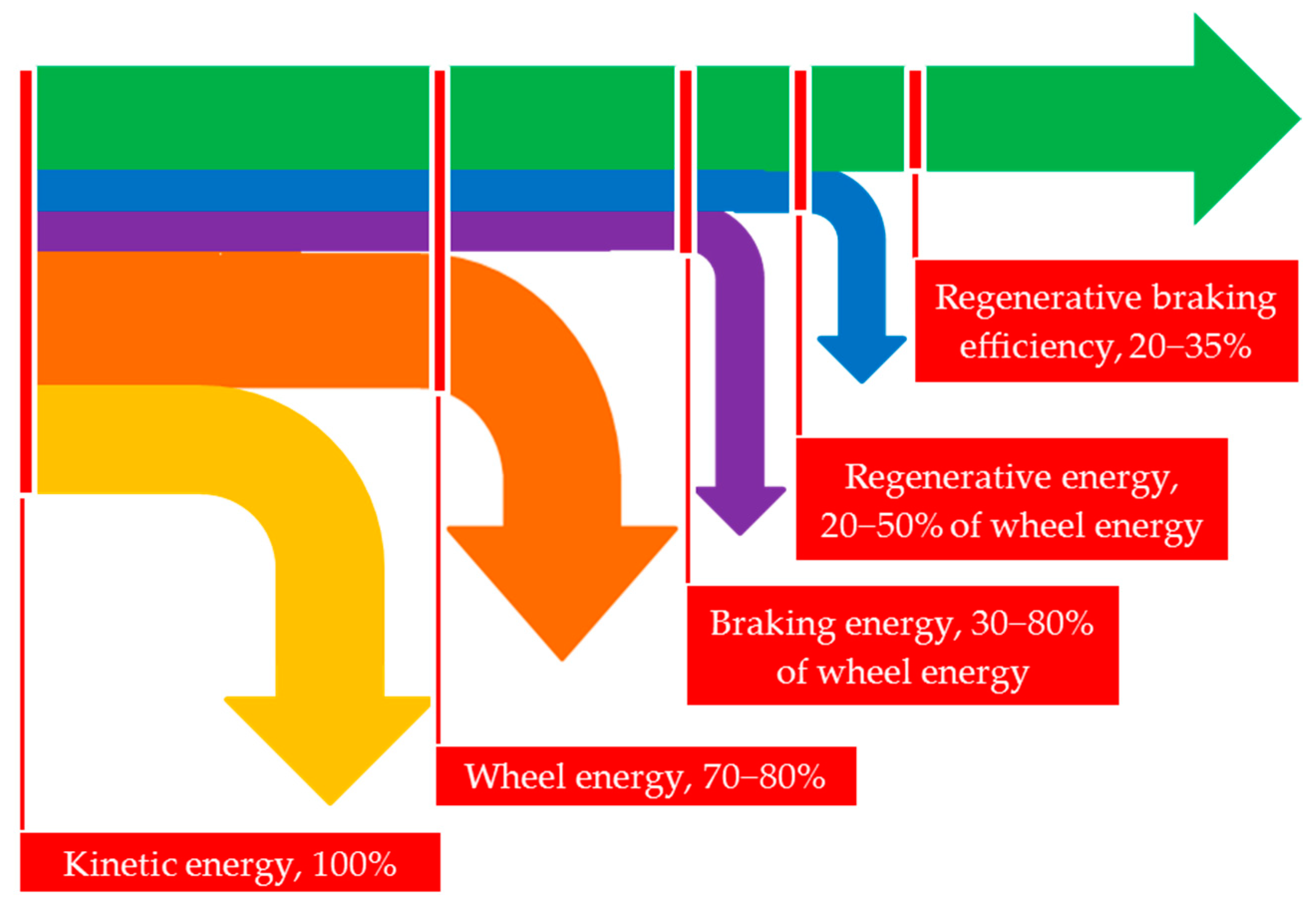
EV energy management has been studied intensively in the last few decades, resulting in several books [8,9,10] and multiple research articles [11,12,13,14,15,16] devoted to this problem. After a thorough examination of numerous literature sources, a diagram of the vehicle energy distribution was designed (Figure 1).
As follows from Figure 1, from 30% to 80% of the vehicle kinetic energy can be used for braking. Since this percentage depends on the braking organization and management, the energy recycling issue seems currently of great importance to boost the driving range, prolong mileage, and increase the EV efficiency. In addition to the overall efficiency improvement of the vehicle, regeneration can significantly extend the braking system life, because the mechanical parts wear out much more slowly.
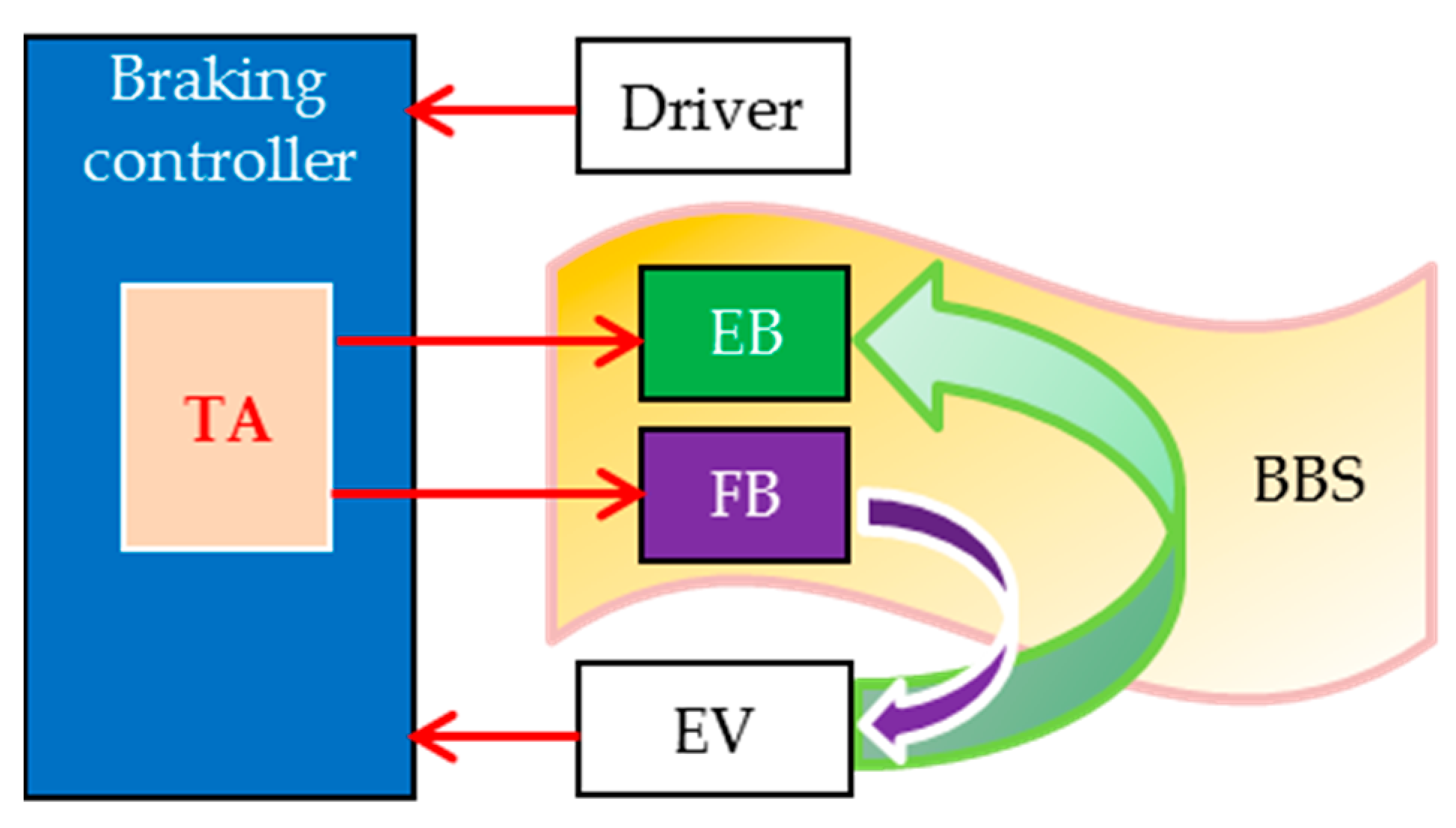
In Figure 2, a generalized composition of a braking system to be analyzed in this review is presented.
Here, EB and FB can perform separately or together in an integrated blended braking system (BBS), whereas a specific torque allocator (TA) module of a braking controller decides which braking scenario to run in one case or another.
1.3. Hybrid Energy Storage
To increase the regenerative braking efficiency, two directions are discussed, namely, enhancing the battery capacity and recharging the battery during driving.
Rechargeable batteries have become one of daily life’s necessities. Gradually improving energy storage devices have pushed transportation to raise the energy density of batteries, up to 200 Wh/kg and higher. Nevertheless, despite the continuous evolution of battery technology since its invention in the early 1800s by Alessandro Volta, the battery supply remains the “weak link” for the observable future, and designers are forced to adapt to this constraint and refine the equipment around it.
As the main step to prolong battery operation and encourage energy recovery, most EV manufacturers promote hybrid energy storage (HES) that combines the battery with high energy density ability and ultracapacitors and/or flywheels with high power density ability [17,18,19,20,21,22,23,24]. Ultracapacitors and flywheels have low energy density, but their power density is 10 to 100 times greater than that of batteries. At the same time, they possess a lower risk of pollution and have superior low-temperature functionality. Their life is over one million cycles, i.e., much longer than that of batteries, which is a very important feature for automotive applications undergoing frequent charge/discharge cycles. These characteristics allow for achieving an improved overall EV efficiency with fast acceleration and deceleration thanks to rapid kinetic and electrical energy exchange.
Nevertheless, frequent HES overcharging without proper regulation can lead to dangerous current surges due to unpredictable energy being injected directly into the HES. As a result, HESs built on lithium-ion batteries can die rather quickly. The traditional engineering solution for this problem is to assign charging power restrictions using the HES state of charge (SOC) and temperature as control inputs. At the same time, the discharging energy is also limited, ensuring that no excessive power is drawn from the HES during aggressive acceleration.
In a battery/ultracapacitor HES design, it is important to maximally utilize the ultracapacitor, aimed at protecting the battery and increasing the overall performance of the EM. In this way, during the EB process, the ultracapacitor receives as much power as possible, whereas the batteries consume the rest. Thus, all available regenerative energy is delivered to the ultracapacitor until it achieves its full SOC, with any excess power then going to the batteries and, finally, to the FB.
HES has been actively cultivated within the framework of the progressive brake-by-wire (BBW) technology used by Toyota®, Ford®, General Motors®, and other companies. BBW systems identify the EB as the primary mode of slowing the vehicle unless the SOC of the HES is too high to accept the additional energy or an urgent stop situation is detected by the system. In practice, the BBW is now a standard even for inexpensive cars and trucks, and every new vehicle benefits from the optimized braking, enhanced deceleration, and improved stability that this technology provides. According to [25], contemporary BBW-based automatic regenerative control equipment is able to successfully reflect all of the driver’s requests.
2. Braking Tools and Modes
2.1. Braking Controllers
A braking controller is the core part of the braking system shown in Figure 2. It implements the required braking scenario and activates the EB, FB, or both in order to decelerate a vehicle and absorb its energy. Different classifications of controllers are discussed in reviews devoted to the applied braking techniques that compete in the market.
In [26], a classification of controllers suitable for gradual smooth deceleration was proposed. In [27], the urgent (called also heavy or emergency) braking mode was studied and appropriate equipment was classified. In [28], the same controllers were divided into model-based and rule-based, depending on the algorithms they translate. The former controllers are typically related to physics models with vehicle parameters and tire characteristics. The latter ones are currently predominantly used in vehicles. They process easily accessible data regarding the speeds of the wheels to generate the torque reference signals.
Nevertheless, neither of the above classifications suits this review, which mainly focuses on energy recovery abilities for gradual and urgent vehicle braking. Therefore, a literature analysis related to energy management at braking was carried out according to the following categories [29]:
- By braking modes—for gradual braking and urgent braking;
- By estimation of the road surface—with no estimation and with surface estimation tools;
- BY braking torque sharing—with fixed torque distribution and with its smart allocation;
- By the toolboxes used for simulation—MATLAB/Simulink® (MathWorks, Natick, Massachusetts, USA), AMESim® (Siemens PLM Software, Plano, Texas, USA), CARSim® (Mechanical Simulation Corporation, Ann Arbor, Michigan, USA), and co-simulation, including digital twins;
- By the tools used for model validation—without verification, with physical imitators, and with real vehicles.
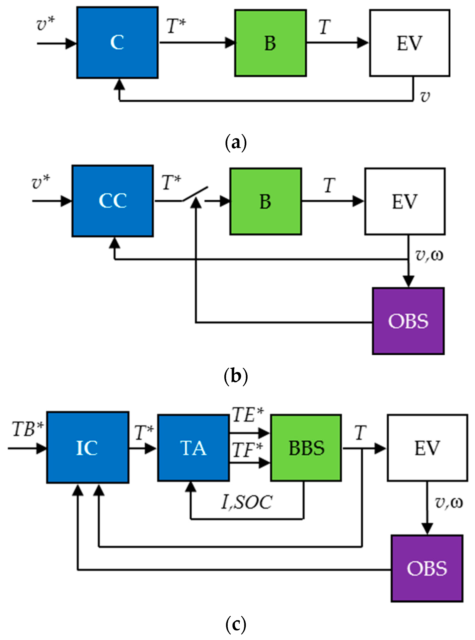
To differentiate between controllers, it would be useful to start with the basics. Given that an initial goal of the braking controller is to initiate vehicle stopping at a required pace, the simplest approach is to use the traditional closed-loop circuit shown in Figure 3a. Here, a controller C compares the reference speed to the real speed of the EV and generates the torque reference to the brake, which produces the reference braking torque. However, the EV cannot process very high braking torque due to its inertia, wheel locking and slip, nonlinearity, and many road obstacles. Therefore, an additional observer OBS has to periodically interrupt or decrease the reference of the conventional controller CC as shown in Figure 3b. Moreover, since energy recovery is in the review focus, the BBS places additional current and SOC restrictions coursed by the EB. For this reason, a TA module fed by an intelligent controller IC can be utilized, as shown in Figure 3c.
As a result, all controllers in this research are divided into those that are able to save energy and those that do not have this ability. The former ones are additionally subdivided into conventional (road-independent) and intelligent (road-dependent).
Conventional braking controllers manage either gradual or urgent braking. In their designs, the road surface under the tire is not identified and, therefore, instability of the driving environment is ignored. Depending on the braking scenario, at least three types of the conventional controllers are exploited in transportation, namely, proportional–integral–differential controllers (PIDC) and their varieties, such as PI and PD, threshold controllers (TC), and sliding-mode controllers (SMC).
Intelligent braking controllers take precedence over conventional ones in management of vehicle deceleration on volatile road surfaces, slopes, and aerodynamic conditions. Unlike the previous class, in which the controller is designed for either gradual or urgent braking, intelligent converters can carry out both gradual and urgent braking in a BBS for the sake of boosting energy efficiency. This class involves fuzzy logic controllers (FLC), neural networks (NN) embodied in appropriate neural network controllers (NNC), and model reference controllers (MRC), as well as their multiple options, such as fuzzy PIDC, neuro-fuzzy controllers, and neuro-MRC.
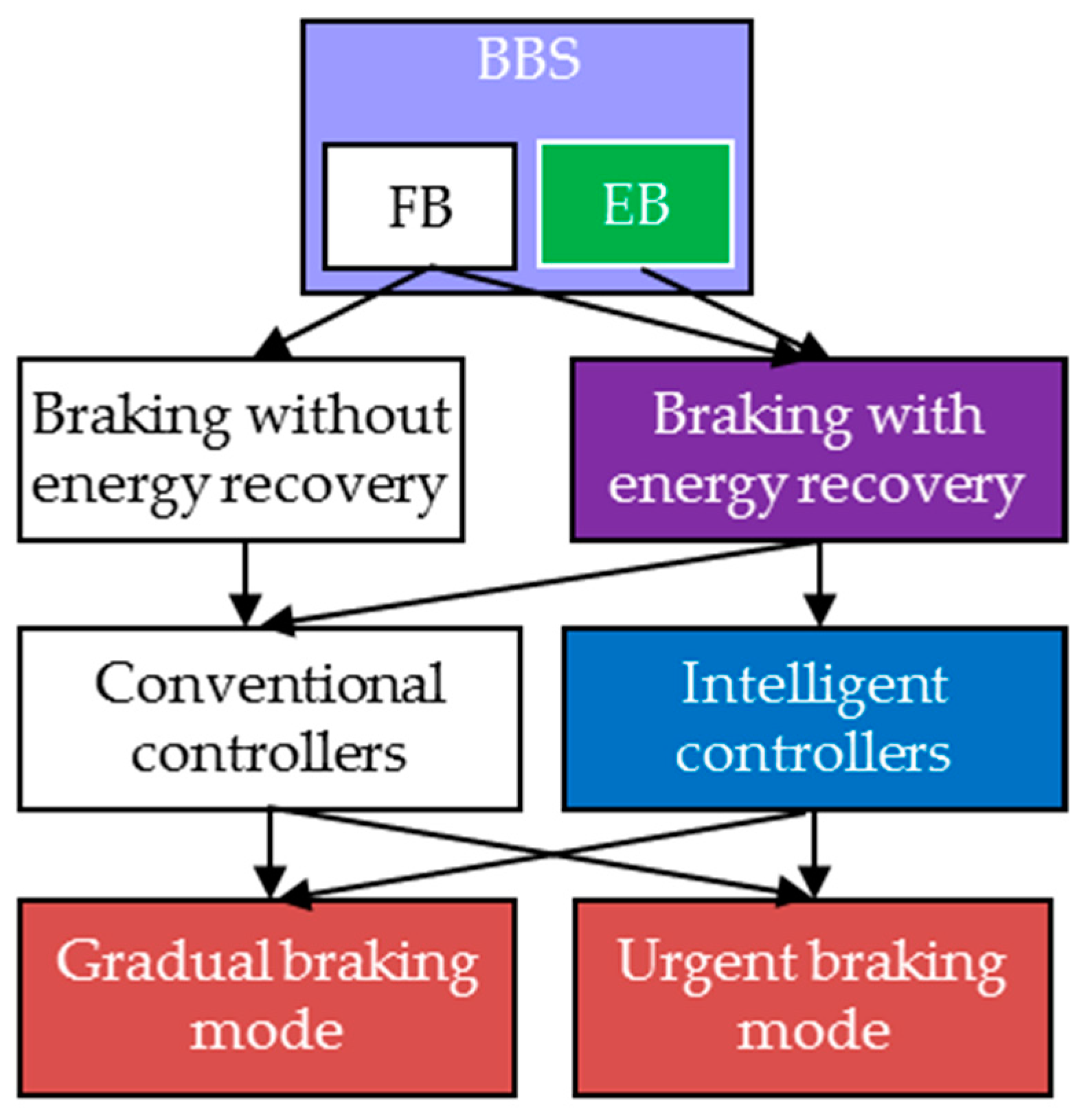
This classification is shown in Figure 4.
Figure 4 can be used to specify the issues addressed in this paper, which focuses on urgent and gradual braking with energy recovery thanks to the maximal involvement of EB under the guidance of intelligent controllers.
To compare different solutions, it was important to validate the results published by different authors. Therefore, both the simulation tools and the model verification tools are carefully analyzed in the review. Taking into account the importance of experimental studies, special attention was paid to hardware-in-the-loop (HIL) [30,31,32,33] and real vehicle testing techniques used for verification of the developed systems with respect to most control aspects.
2.2. Gradual and Urgent Braking Modes
Gradual braking control aims to respond to the driver’s accelerator pedal request as accurately as possible. Gradual braking is used to decelerate the car in front of a traffic light, ahead of a pedestrian crossing, in a parking lot, or when driving downhill. This is rather static compared to dynamic mode, suitable for energy optimization with minimal FB involvement. In terms of energy recovery during car deceleration, regenerative EB has many preferences. That is why EV designers, such as [18,34], applied the EB for vehicle gradual slowing and downhill movement. Several studies were conducted in this direction to minimize the energy lost during the gradual braking [35,36].
The main difficulty during gradual braking control takes place because the braking system of the road vehicle includes a time-variant and nonlinear plant with significant dead time. Thus, variations in weight, tire–road friction, driveway inclination, wind speed, and other properties significantly affect the braking performance [37]. Deviations of many parameters and steering conditions from known values course driving deterioration, resulting in larger overshoot, longer settling times, and sometimes unstable EV behavior. In order to govern vehicle deceleration properly, specific braking controllers were designed that could make decisions on the basis of online solutions of nonlinear equations to accurately activate the brakes.
As opposed to gradual braking, the main target of urgent braking control is to minimize the braking time and distance. The system has to respond as quickly as possible when the driver sharply presses the brake pedal. During urgent braking, the driver’s braking energy request often exceeds the ability of the HES. Despite the fact that EMs are capable of developing great torque rapidly, this is not enough to produce the total braking force needed to ensure rapid stopping of the steerable EV due to the HES overheating and its SOC threshold saturation. As the regenerative power cannot meet the intensive braking requirement, the use of a traditional FB is assumed instead of EB or together with EB to slow the car in the frame of the BBS, which combines FB with EB. In the BBS, the urgent braking and the gradual braking parts are usually separated because of their different targets. Regrettably, the use of FB leads to braking energy wasting and a reduction in the EV lifetime, along with pollution of the environment with tire particles.
Little attention is paid to BBSs that might integrate both the intensive and the gradual braking abilities within a common BBS module. FB and EB have been successfully operated together in only a few cases [38,39,40], in which the BBS was so versatile that it successfully implemented both braking modes. In [41], a BBS incorporating a set of electro-hydraulic systems was designed for EVs. As another example, several braking systems of electric buses can be considered [39]. Unfortunately, their permanently working FBs badly adjust the braking force and easily lock driving axles.
2.3. Antilock Braking Systems
The challenge with urgent braking is that the vehicle may skid and its wheels may lock. Thus, a difference can appear between the expected and real distance traveled by a vehicle due to tire slip, which occurs when the wheel rotates slower than the vehicle would normally demand [10]. The reason lies in the complex physical processes mediating the tire and road surface contact, which results in wheel sliding or even locking. Due to the tire’s elasticity, it deforms to a greater or lesser extent depending on the road pavement, weather, and wind.
To mitigate slip, antilock braking systems (ABS) are used in road vehicles. Once the brake pedal is pressed suddenly, the braking observer monitors data acquired from the speed sensors located in each wheel hub to determine when a wheel has an improper speed. If wheels slow or stop spinning, the ABS alternately increases and decreases the braking torque in accordance with a particular antilock law. The rapid squeeze and release forces the vehicle to slow down and stop without the wheels ever truly stopping, allowing the driver to maintain steering control [42,43,44].
It is worth noting that execution of the classic ABS is accompanied by at least two issues from the standpoint of energy saving.
First, since the ABS is initially configured for high-speed driving on a straight dry road, it might take a longer time to stop in volatile and unknown road conditions. As soon as snow, rain, or loose gravel appears, the ABS may lengthen the braking time and distance instead of shortening.
Second, to ensure proper management organization, the ABS is often separated in the vehicle braking system, being focused on fast and reliable deceleration. Most ABSs are FB-oriented modules that are not engaged in solving any energy recovery problems.
3. Conventional Braking Controllers
3.1. Operation
Conventional braking controllers are used either to adjust gradual vehicle slowing or to provide its urgent stopping. Commonly, braking systems with conventional controllers have the topologies shown in Figure 3b. To initiate braking, the controller first has to identify the presence of slip or lockup, then select the braking tool to employ either the gradual (EB-based) or the urgent (FB-based) braking equipment, and lastly adjust the selected brake. In the scope of these tasks, the speeds of the wheels are monitored and compared with each other with the help of a specific observer, and the SOC of the HES can be additionally estimated to check if the EB is possible.
The typical operating sequence of conventional braking is as follows:
- The driver presses the brake pedal or releases the accelerator pedal;
- The master cylinder of the EV converts the pedal movement to hydraulic pressure and the pressure transducer creates the braking torque desired;
- The braking controller examines the driver’s request aiming to determine if a gradual braking or the ABS algorithm is required;
- If urgent braking is requested, the controller runs the ABS and repeatedly observes the speed sensors to prevent wheel lockup;
- If gradual braking is requested, the braking controller then evaluates the SOC of the HES;
- Depending on the SOC, the braking controller runs either the EB or the FB;
- In the case of the EB, the propulsive EM serves as a generator, which converts kinetic energy of the EV to electrical energy of the HES;
- Once the speed drops below about 10 km/h, the FB runs alone, as the EB does not benefit at low speed.
3.2. PID Controllers
PIDC is the main candidate for a gradual single-input, single-output (SISO) controller [33,45]. The PIDC works properly only when the vehicle parameters and disturbances are fixed and well known. In this case, the PIDC tuning procedures are rather elaborated for the offline and online scenarios. Offline tuning takes into account the mathematical model of the EV and driving conditions, as well as their time constants and gains. In practice, offline tuning follows the characteristics, critical points, and typical responses of the vehicle, such as step, frequency, and closed-loop relay feedback. Most often, well-known tuning methods are used such as Ziegler–Nichols, Chien–Hrones–Reswick, Cohen–Coon, or their combinations [46] that maintain standard closed-loop operations. However, due to a broad range of uncertainties, numerous data cannot be preliminary known offline. For this reason, a second step called autotuning is considered to correct PIDC settings online and meet the real-time obstacles. The above reasoning provides rather accurate controller settings when the EV runs steadily and the driver’s references change to a greater extent and more quickly than the control variables and disturbances.
The PIDC can also operate successfully with ABS. Several examples of the FB-oriented PIDC used for urgent EV braking can be found in [27,47,48,49]. Nevertheless, the energy saving issues are not resolved in these cases.
At the same time, since the PIDC tuning simultaneously focuses on three interrelated gains, the use of the PIDC in transportation management has many restrictions, as listed below.
- In nonlinear and unstable circumstances, when the road and weather change unpredictably, the optimal settings obtained in the initial context do not provide an optimal response in other conditions [50];
- PIDC works well for small deviations of the system variables, whereas during sharp deceleration and considerable speed or torque changes, the EM current and voltage restrictions destroy the control loop performance and can cause feedback disconnection [51];
- PIDC is a SISO controller, whereas circuits with multiple inputs and multiple outputs (MIMO) cannot provide acceptable performance due to improper interaction or coupling of separate PIDCs or their parts [33];
- PIDC is ineffective and often completely fails in adjusting the objects with long dead time common to some vehicle systems. For instance, the PIDC-based dynamics model of EV developed in [45] estimates the effect of parameters on the car performance and energy consumption. It also does not optimize energy recovery because it only considers permanent driving conditions. The same may be said regarding the solutions proposed in [49,52].
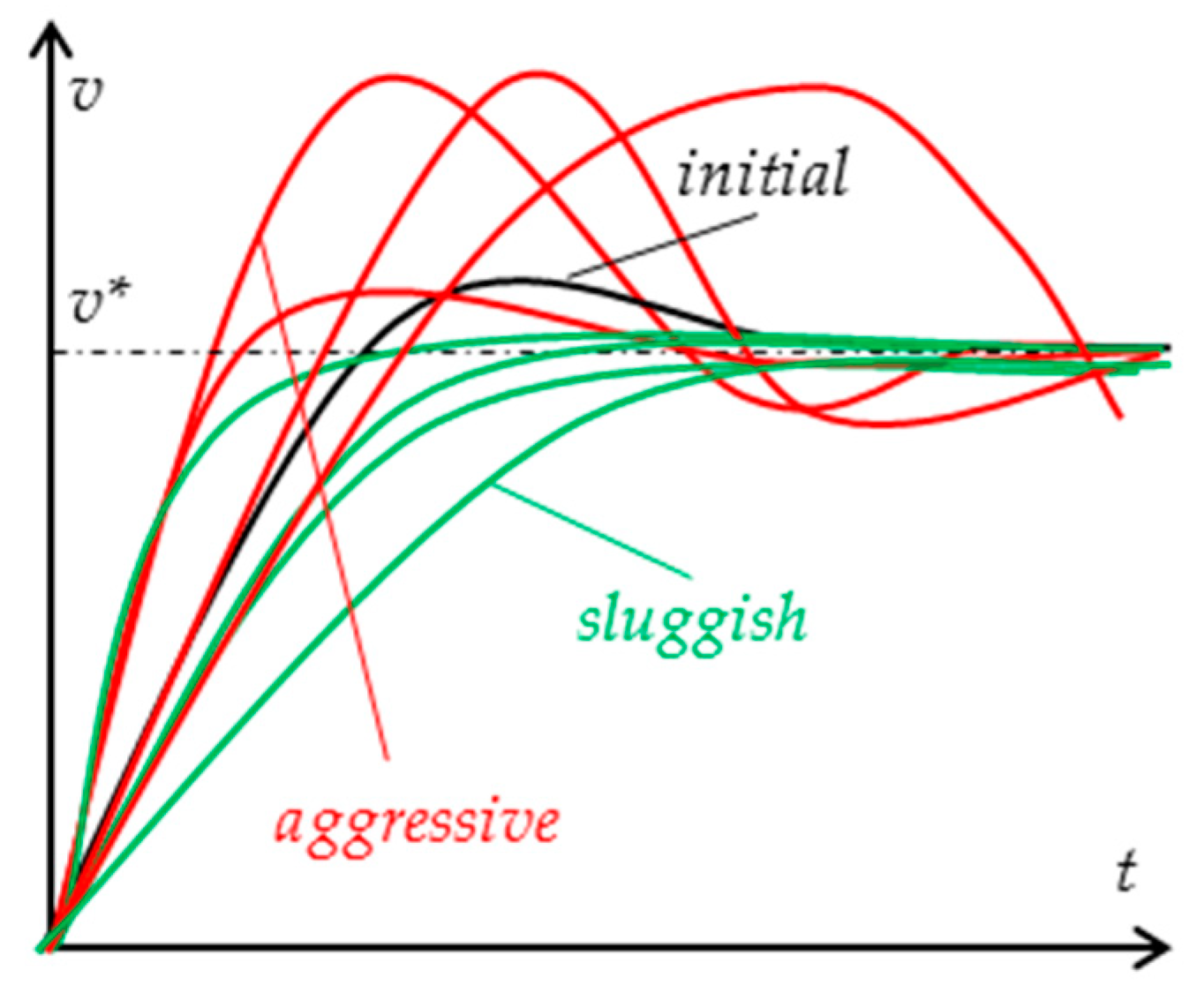
These challenges are illustrated, in particular, in [53], whose step responses and distortion combinations for the angular speed of the vehicle wheel fed by the PIDC are shown in Figure 5. Here, the PIDC tuning relies on the approximated disturbance and plant models. Issues such as load instability and system nonlinearity distort loop behavior. As a result, the loop becomes either excessively aggressive (red lines) or too sluggish (green lines).
3.3. Threshold and Sliding Mode Controllers
The most convenient control strategies for urgent braking process are based on the logic threshold and sliding approaches.
Commercial ABSs mostly employ TCs having permanent thresholds for different parameters and a number of rules that define control activity [54]. By introducing a simple threshold function, a satisfactory trajectory tracking performance can be carried out, in which torque saturation is considered. Wheel speed observers are used to detect wheel lockup, wheel stops, or wheel skids. When a lockup is diagnosed, the ABS under the threshold control works by releasing and then reapplying the brakes to car wheels several hundred times per second. This mitigates the wheel skidding and helps keep the steerable control of the vehicle.
Usually, TCs are FB-oriented, with no energy recovery abilities. For example, an ABS of Bosch® [10] acting in braking hydraulic systems of passenger vehicles implements eight-step logic to switch the braking mode depending on the slip. The following control operations are used there: pumping by brake pressure increasing, dumping by brake pressure drooping, holding by keeping constant brake pressure, and pump holding by increasing brake pressure in steps.
As a step forward, [55] proposed an EB-oriented ABS control strategy. Here, the controller observes the braking torque of the EMs for understanding when the peak of the braking force is reached to start regeneration.
However, the thresholds obtained from several experiments often have great deviation from the real value because of changing tire–road friction, vehicle speed, and wheel slip level.
In this regard, the SMCs deal better with uncertain, nonlinear, and changing dynamics of the urgent braking scenario.
Most of them, for example [56], successfully maintain the FB. The authors of [57] described two sliding-mode algorithms, namely, the Lyapunov-based SMC and the reaching-law-based SMC. Both these options, designed and applied in the strongly nonlinear ABS, proved their good acting over control operations. They do not have extreme computational complexity, relying instead on a reduced number of tuning gains.
In [58,59,60], the SMCs used in EVs opened up many attractive opportunities for energy recovery. In [61], an ABS design was proposed on the basis of an SMC, which maintained the optimal wheel slip during regenerative braking. There, an exponential law was used to reduce chattering. In [62], an improved SMC combined with the vehicle dynamics model and brake force observer was presented. Their co-simulation was produced in Simulink® and CarSim® toolkits. In [63], the SMC was united with a classic PI controller in a hybrid conventional controller unit.
Regrettably, all SMCs are very sensitive to the accuracy of measuring devices and operate badly with sensors in a noisy environment.
4. Intelligent Control of Braking
4.1. Operation
Today, intelligent controllers, including FLCs, NNCs, MRCs, and their associations, serve as efficient tools to manage nonlinear and nonstationary plants [64]. Usually, the braking systems with intelligent controllers have the topology shown in Figure 3c. The two most significant reasons that lead to intelligent control involvement are, first, the road surface identification and, second, optimal distribution of the braking torque between front and rear wheels, along with its sharing between EB and FB. Both of them are very important features in terms of maximizing the amount of regenerative energy because of their capability to solve a braking problem together with an increased energy recovery.
In addition to the accelerator and brake pedal positions, as well as wheel speed and SOC of the HES, several intelligent controllers monitor more input signals, such as vehicle speed, yaw angle, stroke and steering wheel angle, hydraulic actuator pressure, and pressures of wheel caliper circuits. Other inputs can also be sensed.
The typical operating sequence of the intelligent braking controller is as follows:
- The driver releases the accelerator pedal or presses the brake pedal;
- The master cylinder of the EV converts the pedal movement to hydraulic pressure and the pressure transducer creates the braking torque desired;
- The braking controller inspects the driver’s request aiming to determine if a gradual braking or the ABS algorithm is required;
- In the case of urgent braking, the braking controller observes the vehicle and wheel speed and calculates the slip aiming to correct the braking torque desired to prevent wheel lockup and maximize the amount of regenerative energy;
- The braking controller then checks the SOC of the HES;
- Depending on the SOC level, the braking torque is distributed between the forward and rear wheels and allocated between EB and FB;
- In the case of EB involvement, the propulsive EM is used as a generator, which converts vehicle kinetic energy to electrical energy of the HES;
- Next, the braking controller estimates the yaw and steering wheel angles;
- Depending on vehicle yaw and steering angles, the system initiates an appropriate vehicle stability algorithm;
- Once the speed drops below 10 km/h, the FB runs alone since the EB does not benefit at low speed.
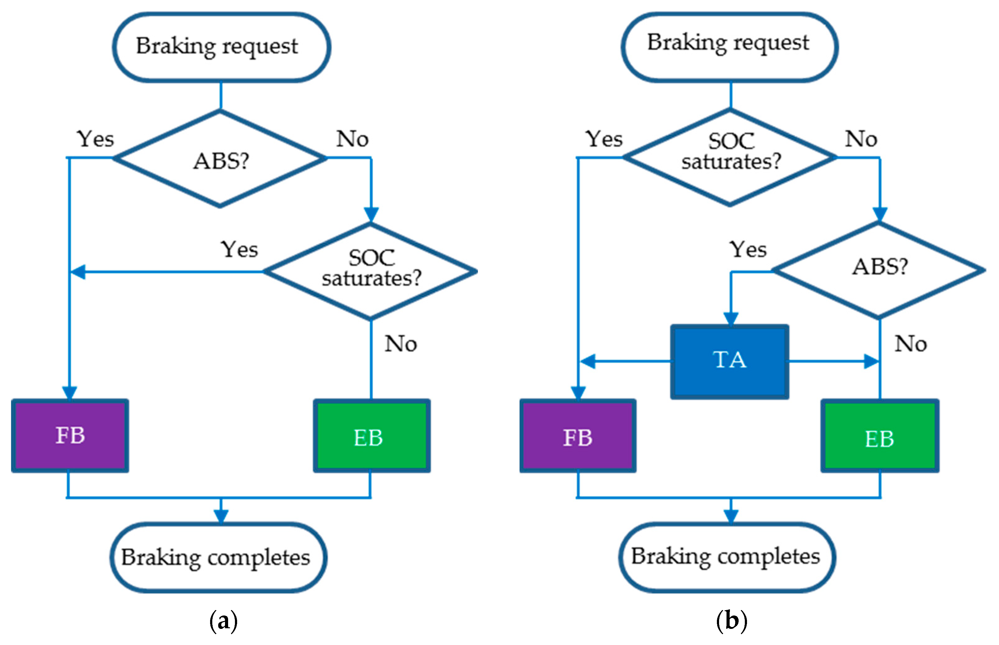
The main differences between conventional and intelligent braking algorithms are demonstrated in Figure 6. In the former case, the EB serves as an additional feature, whereas, in the latter algorithm, the EB is a primary tool.
For the systems that have nonlinear and time-variant plants with significant dead time, multiple intelligent control approaches were published recently. The most progressive of them, for instance, [65,66,67], successfully evaluated a priori unknown changes in the driving conditions over time in order to identify the environment and handle nonlinear vehicle dynamics.
Adoption of intelligent controllers is especially important during urgent braking because the ABS driven by conventional controllers performs poorly in volatile and unknown road conditions [18,19]. On the other hand, intelligent controllers are also capable of successfully improving energy efficiency during gradual braking.
4.2. Road Surface Identification
An important issue for intelligent control is related to the methods applied for identification of the road surface under the tire. It should be noted that most intelligent controllers are aimed at maximizing an urgent braking torque and not the amount of regenerative energy. In this regard, different friction-slip models may be found in the literature, such as Pacejka’s “Magic Formula”, the Burckhardt model, and the Rill model [47,68].
A thorough review of the tire–road friction estimation methods in [56] and studies such as [69,70] focused on different techniques and, in particular, on perturbed SMC-based road surface observers.
The method established in [71] introduced small oscillations to the reference torque with subsequent evaluation of the phase shift and amplitude of the wheel speed oscillation. Their levels affect the model of the vehicle at its operating point, as well as the wheel slip and road features. Unfortunately, the method simulated in the MATLAB/Simulink® toolbox never received experimental validation.
In [72], six different powertrain architectures were mathematically modeled and analyzed under various driving conditions based on EV nonlinear models. In [27], an accurate ABS operation environment was presented in MATLAB/Simulink® software. However, neither solution, built considering a permanent theoretical tire–road representation within the fixed friction factor ratio of 0.2 to 1, could minimize energy consumption. Since the controller ignores the volatile road environment, it has to reduce the reference torque in off-road driving.
The same constraint decreased the quality of the design created in [44], where the tire-road friction was derived relying on the speed sensor signals and vehicle geometry. The braking controller detected the discrepancy between the reference slip and real slip as the input signal and created the reference braking torque in the output. This method was proven to be successful for unmanned aerial vehicles. In [73], the same input was used to search for the optimal reference slip to control the pressure of a four-wheel hydraulic brake. Both solutions were designed for an internal combustion engine-fed vehicle without braking energy recovery.
The method offered in [31] used a model built on a road file, created by a direct measurement from a GPS® device (Peterson Air Force Base, CO, USA), Google Earth® (Google, Mountain View, CA, USA), or any other toolbox compatible with the CarMaker® (IPG Automotive GmbH, Karlsruhe, Germany). This tool helped the designers evaluate the energy consumption of the EV Tesla Model S® (Tesla, Palo Alto, CA, USA). By simulation, a dependence was found among the EV range, HES SOC, vehicle weight, and number of batteries. Regrettably, this research did not directly concern the braking issue; therefore, no energy management improvements were suggested there.
In [74], the variations in the tire properties, road pavement, and vehicle slowing were evaluated on the basis of the position and rate of the brake pedal pushing, vehicle speed, and wheel slip used as the controller inputs. This article eliminated EB in the ABS, which was separated from the BBS.
In contrast to the above studies, the friction-slip estimation methods proposed in [75,76] were directly related to the energy saving problem solution. There, the designed controller operated under various driving scenarios including gradual and urgent braking on different pavements, integrating the strengths of both the FB and the EB. The vehicle model reflects numerous factors, such as road incline, aerodynamics, and tire–road characteristics. The new tire–road model recognizes the road pavement at various speeds. The SOC and electric voltage/current limitations of the HES are taken into consideration. Thanks to multiple benefits, these researches formed the basis for the follow-up studies of the authors.
A reset tool [48] proposed in [77] determines the type of road under the tire and calculates the braking strength. Using this method, a controller is periodically returned to the zero state with holding a previous surface value. At that, a high torque pulse is applied and the braking system evaluates the maximal EV deceleration to choose a relevant wheel-slip from the database, aiming to generate the highest torque reference possible at this friction.
4.3. Sharing the Braking Torque
When discussing the braking torque shared among the BBS components, three approaches attract attention, namely, torque sharing between right and left wheels, torque sharing betwefront and rear wheels, and torque sharing between the EB and FB.
The braking controllers described in [63,78] serve as the coordinators and supervisors of torque sharing. If the requested braking torque is higher than the maximum achievable EB torque, the FB is activated by the braking controller targeting to increase the torque to the full requested level.
In [67], the braking force was shared between the front and rear wheels by a permanent ratio derived from the car model. The control algorithm uses the car speed, brake pedal position, and SOC of the HES as the braking controller inputs and assigns the ratio of the EB force to the full braking force as the controller signal directed to the BBS.
The same target can be found in the braking system offered in [34]. Using the created model, a regenerative braking procedure and respective controller were developed focusing on the braking torque sharing. Torque allocation between the EB and FB modules was aimed here at creating maximal energy by the BBS. To get the highest regeneration capacity, the EB is involved in providing energy exchange in the best possible way. This procedure addresses the efficient and reliable integrated operation of EB and FB. Unfortunately, in both [34,67], the co-simulation conducted in the MATLAB/Simulink® toolbox together with AMESim® software was not tested by experimentation, and the benefits of the designed procedure over other solutions, such as [79], seem ambiguous.
A performance algorithm of torque allocation proposed and verified in [76] represents another step forward in this direction. Here, once the controller detects the braking torque request, the EB runs. The FB torque is not produced until the SOC exceeds a permissible overcharging barrier or the EM produces maximal power. Since the torque developed by EM becomes insufficient, both the FB and the EB run together. In the case when the SOC level exceeds its boundary, the FB runs separately because regeneration is now impossible. The main advantage of this approach consists of the involvement of regeneration in all braking scenarios, including urgent ABS-fed braking.
5. Fuzzy Logic Controllers
5.1. Fuzzy Control Functions
Deep analyses of FLC-built equipment were presented in [77,80]. In these and similar contributions devoted to braking under the fuzzy control, different responsibilities are assigned to the FLC.
An FLC is capable of controlling complex nonlinear plants that are described qualitatively because of their mathematical characterization difficulty. The FLC does not need an accurate model of the system, but requires a linguistic description of the input-to-output ratio. In contrast to classical binary logic, which deals with the sets of logical variables that are either their members (true, 1) or not members (false, 0), the fuzzy sets of linguistic variables are capable of partial membership between the full absence of membership (0) and full membership (1) instead of crisp membership. The membership function linking any linguistic variable value with its degree of membership in fuzzy sets can have variety of shapes.
Numerous FLCs have demonstrated improved operation of high-order nonlinear and dead-time systems. Multiple fuzzy tools have been developed to control the urgently braking vehicles using the FLC [75,81,82]. In all of them, the FLC implements enhanced guidance comparing to the conventional controllers by successful handling uncertainties in a noisy environment.
From the literature review, the following two areas of fuzzy control can be distinguished: fuzzy generation of the braking torque and fuzzy sharing of the torque generated. Both of them contribute to the promotion of energy saving.
With regard to the first direction, attention can be primarily drawn to [83], where a FLC-based braking procedure was developed to provide regenerative braking. In [84], fuzzy control was used to stabilize a plant moving in unknown environment. To increase the efficiency, a bi-level supervisory controller was used in this FLC. The fuzzy approach offered in [85] derives the control signal and applies it to stabilize the chaotic system. Methods offered and validated in [27,77] used the HIL testbed and a multi-input, single-output (MISO) FLC to handle the ABS. Here, both the longitudinal slip and the vehicle speed were considered as the inputs, whereas an actuating torque was generated in the FLC output.
5.2. Challenges of Fuzzy Control of Braking
It should be noted, however, that fuzzy methods demonstrate their drawbacks when working with continuous processes, such as those that are considered for gradual deceleration, when a set of variables must be taken into account to generate control actions.
The FLC is usually designed case-by-case instead of systematically. For that, the trial-and-error method is applied, guided by a designer experienced in fuzzy logic. Such an approach makes the FLC infeasible in many automation systems due to the complexity of their nonlinear input/output ratio and difficulty in identifying a great number of tuning settings, scaling factors, linguistic rules, and the shape of the fuzzy surface [88,89]. Since the tuning of the FLC requires high-skill specialists, the fuzzy logic approach does not play the leading role in the management of gradual braking. Furthermore, the common FLC cannot avoid steady-state and static errors and fails in dynamics contrary to the PIDC, which is able to operate without static errors, along with its easy use, structural simplicity, and good robustness.
The following weaknesses of FLC may be noted in terms of EB:
- Distinct from PIDC, the FLC does not support internal dynamics because its input/output surface usually has a stepwise pattern uncomfortable for smooth deceleration during highway cruising, slowing down, or parking;
- Attempting to develop a universal FLC commonly fails because of difficulty in establishing fuzzy links between a number of variables only on the basis of intuition and system observation;
- FLC design and tuning carried out as a decision-making process drawing primarily on human skills and expertise are usually rather sensitive to developers’ knowledge, thus mitigating reliability of control, although several new fuzzy SMCs and adaptive FLCs have alleviated difficulties in creating the fuzzy rule base to a certain extent [90].
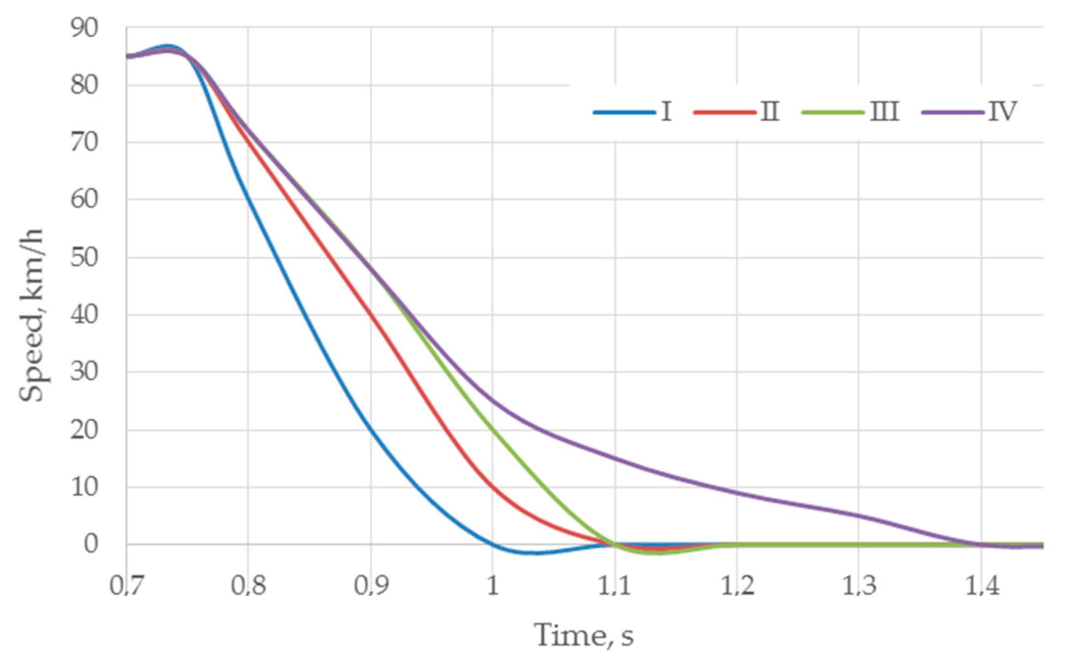
These challenges are clearly illustrated in [91], where four different rule bases were designed. One fragment if this study is approximated in Figure 7. Rule base I had a commonly used symmetrical dispersion showing smooth and rather fast slowing down under the comparably high slip of about 50%. Rule base II was more sensitive to the vehicle speed than other rule bases although it implemented the fastest braking, with possible wheel blockage. Conversely, rule base III was exposed to show quite a fast response compared to rule base IV, which represented very slow braking.
Hence, most popular FLCs are suitable for specific sets of parameters and features. Common implementation of FLCs is restricted since they need regular retuning whenever there is a change in the specifications or environmental data. In particular, in [67,92,93], FLCs were exclusively utilized for urgent braking. In [94], the only object of the FLC was parking. The FLC in [81] was aimed at keeping a safe distance from the preceding vehicle by adapting the speed of the host vehicle. Using brake and throttle settings as input variables, the vehicle speed and deceleration were adjusted there to avoid accidents. However, this MIMO-based FLC had many problems with tuning. The same issues were underlined in [95].
5.3. Fuzzy PIDCs
As mentioned earlier, PIDCs are ineffective in processes with long dead time, upon great deviations of the controlled variables, such as during sharp deceleration and considerable speed or torque changes. A fuzzy PIDC often helps to resolve these conflicting issues. A thorough review of this intelligent equipment was presented in [26].
In the fuzzy PIDC, two groups of parameters are processed, namely, the scaling factors and the fuzzy rule base [96,97,98]. It has been proven since [88,99] that fuzzy PIDC has better handling abilities than the PIDC and FLC. It has the same structure as the classic PIDC in proportional, integral, and derivative terms, but allows changeable settings. The fuzzy PIDC, thus, preserves the simple linear principle and, at the same time, opens up an additional autotuning capability [90,100,101,102].
One of the fuzzy PIDC groups refers to the method of fuzzy gain scheduling, which is used in several professional toolboxes [97,103]. It helps to choose the optimal PIDC settings that better meet the current state of the plant. However, gain scheduling cannot take into consideration all available states of the system and, thus, does not ensure overall robustness.
Some SISO and MISO configurations of fuzzy PIDCs, capable of improving the dynamic and static characteristics of control, were produced including single-input, dual-input, and three-input controllers having one output. The ABS is mainly governed by dual-input fuzzy-PI and fuzzy-PD type controllers invented by Mamdani [104], where the P component ensures given tracking accuracy, the D part speeds up the response, and the I factor is used to eliminate the steady-state offset [105]. In [106], the error of the wheel slip and its difference were used as the FLC inputs and the error entered the PIDC, whose output was used as an increment of the hydraulic pressure. When the slip error was more than 6%, the fuzzy control stopped, the integral constant was zeroed, and the proportional gain obtained a biggest value to shorten the response time.
The authors of [107,108,109] noted the analytic complexity of the MIMO implementation as a negative issue of the fuzzy PIDC, which hampered its construction and autotuning, making the multi-output design rather problematic in terms of the rule base and inferencing.
In addition to solving the main problem, an important idea of several fuzzy PIDC algorithms is the MIMO alignment with the MISO by transforming the speed and the first-order time derivative of speed (acceleration) inputs into an aggregated output having a linear-like control law [110]. A linearized rule base with triangular membership functions is used there, which actually combines fuzzy-PI and fuzzy-PD controllers. In particular, the authors of [99,111] parameterized a Ziegler–Nichols equation using a single parameter. The fuzzy PIDC employed following [107] failed in the use of Mamdani’s fuzzy reasoning, although fuzzy two-term controllers, such as PI and PD [90], PD and I [112], or PD and ID [113], could be successfully realized. The open question of these systems concerns optimal tuning for all PIDC parts. As the control actions are closely coupled, the contribution of separate scaling variables to the output result remains unclear, which makes the tuning method quite unreliable. A more common approach of [100,114] presumed the sharing of the fuzzy operation among fuzzy-P, fuzzy-I, and fuzzy-D independent controllers.
There are quite a few publications devoted to the MIMO fuzzy PIDCs able to transform the speed error and its rate inputs directly to three PIDC coefficients. Some of them represent non-automotive applications, such as steam heaters [115] or robots [112]. In the control system of a transmission grid [116], an error and its rate were input to the dual-input FLC, whereas three PIDC gains served as outputs. In the EM drive [117], the same inputs and outputs of the FLC were used, but the single error was applied to the PIDC input for EV speed adjustment. In [118], a rate of error was applied as the only input signal of fuzzy inference, whereas three PIDC gains served as the outputs. Appropriately, three fuzzy rule bases were designed and simulated in MATLAB/Simulink® software.
To address the issues of nonlinearity and time-variability, the tuning scheme offered in [109] initially assumed nonlinear system dynamics, while real-time implementation was approximated by a linear model with recursively updated parameters. The FLC gains were obtained here by solving a nonlinear optimization task. Two architectures were proposed in this study. The former one solved the constrained optimization problem offline, whereas, in the latter, the gains were updated in real time.
A nonlinear control method was also proposed in [105]. Original lookup tables were invoked in [119] on the basis of experimental trials, in which inadequate performance appeared in many circumstances. This technique is also limited by the fixed set of control properties. With respect to automotive applications, it would result in frequent detuning to meet the worst-case scenarios, for example, braking on an icy road with bad tires.
As an example of a successful vehicle braking system, in [120], the EV was co-simulated in MATLAB/Simulink® and AMESim® software with a two-input, three-output fuzzy PIDC. Fuzzy variables were shared here among 11 levels, from large negative to large positive levels.
Unlike the above studies, [120] focused on the maintenance of not necessarily the best but some optimal braking dynamics in terms of the overspeed and the first-matching time under variable driving scenarios and road surfaces. For that, the paper emphasized two factors, namely, the most precise following the standard dynamics and the fastest achieving the desired speed. The first issue is typical for some industrial EVs operated in more or less stable conditions at moderate speeds (electric cars, forklift trucks, loaders, carriers, and so on.). The second one is related to normal road EVs. The research focused on PIDC autotuning using the slope error and the peak error as input signals applying the MIMO-type FLC. The NI LabVIEW® toolkit was used in this study as a suitable tool for simulation and an intuitive graphics-based user interface for analysis of vehicles and data acquisition in PIDC, FLC, and fuzzy PIDC.
6. Neural Network Controllers
6.1. NN Control Systems
Several review papers gave a comprehensive introduction and opened up perspectives of NN applications in the intelligent control of EMs and EVs [121,122]. The NNC can outperform human experts used in FLC and may be realized more accurately and quickly. The target for using the NNC is to capture the accuracy of experimental data while saving computational time. Since NN-based computing can be carried out accurately within short timeframes, different NN methodologies are applied in braking controllers of vehicles [123,124].
A robust NNC published in [125] guaranteed stability against unknown uncertainties when employing energy-efficient urgent braking on a variable-surface road by tracking the reference wheel slip in different maneuvers. Another paper [126] contributed to the development of an effective engineering solution aimed at improving the ABS control by estimating the friction coefficient with the help of video data. An emerging deep learning method was applied in [127] to evaluate six road pavements and driving combinations: wet gravel, dry gravel, wet cobblestone, dry cobblestone, wet asphalt, and dry asphalt. An experimental investigation of the designed convolutional NN was carried out here to parametrize the vehicle tire model. In [128], a recurrent NN was proposed as a drive cycle recognizer and NNC tuner. This network tracked the last 200 s of computed speed data (average, maximum, and minimum speed and acceleration), using them as the characteristic values for a driving cycle. The NN had six input neurons, 10 neurons with a sigmoid function in the hidden layer, and a single-neuron output layer.
In [40], the NNC provided the torque gradient control with no tire–road models, at which maximal energy was returned to the HES in braking. The proposed algorithm of torque sharing defined how to allocate the driver’s request between the FB and EB to enable regeneration in all braking scenarios, except when using a solo FB if the SOC and voltage levels of the HES are saturated.
The authors of [129] presented an interesting example of an NN-fed BBS. The control problem was formulated here as a search for optimal policy in the Markov decision-making process, where the braking space was defined as a set of actions including no braking, gradual braking, average braking, and urgent braking. The policy used to manage braking was implemented through computer simulation using deep reinforcement learning. Another NNC proposed in [130] processed two kinds of braking operations, namely, releasing the accelerator pedal and pressing the brake pedal. The radial basis function NN was trained here through the optimal braking force, while the multi-correlation coefficient method was used to analyze errors against a sample database. Some standard test cycles, such as US06, UDDS, ECE, and LA92 were implicated for the system validation.
NNCs have been applied successfully to optimize energy recovery in EVs. For instance, a convolutional NN was used in [131] to estimate energy or power consumption of EVs. In [132], a regenerative EB scheme was offered aimed at transferring braking energy to the HES devices. To this end, the multilayer feedforward NNC provided satisfactory capability, comprising the EV speed and SOC of the HES in a number of braking situations. Furthermore, the authors of [133] used real data collected over 2 days of power consumption, trip time, and SOC as training inputs to the NN. The NN output specified the EV recommended operation mode as a function of time, whereas typical peak loads and off-peak load times, human behavior, and seasonal and weather conditions contributed to the model to generate a realistic pattern. One more example is the deep NN-based approach of EV energy demand estimation proposed in [134]. It was based on the driving cycle data properly preprocessed and transformed into 1D or 2D maps to serve as an NN input. Several deep feedforward NN architectures were considered for this application along with various input formats. In [135], the HES-based braking system implemented automatic control of the EV, providing both driver comfort and energy efficiency. To apply this approach, an accurate prediction of the vehicle driving state was produced. An original EV deceleration model developed in this paper was based on the deep NN consisting of a sequential recurrent NN with long short-term memory and a two-layer conventional NN model.
Many NNCs were designed for use in driving scenarios other than braking ones. However, these solutions represent a good perspective in terms of EV braking.
For example, the contributions of [136] were threefold. First, the authors developed an imitation learning method for longitudinal management of vehicles. Second, the paper demonstrated the interventions needed to retrain the NN and to improve its robustness to mistakes. Third, two safety cages were presented that prevent forward collisions during highway driving. The safety cages were applied to manage the outputs of the NN in critical situations, when the NN output was not responding correctly to the danger. Testing under normal and critical driving scenarios on two different NNs demonstrated the prospects of the approach from the standpoint of braking.
In [137], an NNC replaced the PIDC for controlling the position of an EM shaft to drive a vehicle-like plant. This double-input NNC provided supervised learning, during which the dataset used to train the NN was run before simulation. Since the output of the plant was fed back to the NNC input, it could be applied as the NNC backpropagation model of the braking vehicle.
The solution designed in [138] could be employed in both the gradual and the urgent braking modes. During the training, the authors used random sampling to make sure that the numbers of urgent and gradual samples were equal in every batch. Since urgent braking is a rare event, they faced an unbalanced dataset problem, in which the urgent samples were collected five times more than the gradual ones. As a result, a balanced testing dataset was constructed.
6.2. NN-Based PIDCs
One of the directions in NNC implementation into onboard HES focuses on determining the optimal coefficients of the classic PIDC and their influence on power distribution.
The aim of the adaptive self-tuning technique created in [139] was to adjust the parameters of the PIDC with NN using a particle-swarm optimization algorithm. The number of dimensions in swarm optimization was equal to the number of PIDC gains. The mean squared error function was chosen here as a criterion for estimating the system performance quality.
The method offered in [140] combined the conventional PIDC with a single-layer NN, which tuned online the P, I, and D gains of the PIDC. The controller used a desired trajectory and an error as inputs for self-tuning and the NN output as its output. An adaptive linear NN was applied here, in which the least mean squared error algorithm adjusted the weights and biases of the NN targeting to minimize this error.
In [141], the PIDC was fed by an NN with three special types of neurons: P-neurons, I-neurons, and D-neurons, which realized the three fundamental controlling actions. In [142], an adaptive NN-based PIDC was offered for the MIMO nonlinear vehicle system. In [143], the NNC provided twofold lower transition time compared to the classic PIDC, along with a reduction in both the energy loss and the EV speed overshoot. The proposed control method made it possible to automatically tune the PIDC, thus reducing the inrush currents and torque surges, thereby prolonging the service life of vehicle mechanical components. This PIDC could effectively implement gradual braking due to its capability to determine optimal gains of the PIDC and their influence on the energy distribution in the onboard HES of the EV. Adaptive control of EMs takes into account operating conditions, road surface, and other factors. Two options were introduced for the controller implementation: a conventional PIDC and an intelligent PIDC with an observer based on an NN.
Similarly, the NN technique given in [144] was applied to enhance the PIDC operation. This energy management strategy was robust with respect to the load and mass uncertainties. The nonlinear model of a mobile robot considered the robot’s position, speed, and acceleration. Accordingly, the speed was presented on the NN input. The weight updating law minimized the quadratic objective function, which was considered as the training signal. Weight adaptation was obtained using the algorithm of the gradient propagation. The feedforward NNC included a linear input layer, an output layer, and a hidden sigmoid intermediate layer, which used a boundary magnitude function.
6.3. Hybrid NN Controllers
Several examples of fuzzy NN integrated into EVs to improve their energy efficiency can be found in the literature.
In [145], the input constraints considered were the speed and the speed range. The fuzzy NN designed consists of 10 hidden layers with one neuron each. The NN was evaluated using 110 different cases.
An example of a hybrid intelligent controller, in which an FLC and NNC were merged together, can be found in [146], where the FLC was fed by the NN. An NN-based FLC presented in [147] solved the torque distribution problem for regenerative braking of a hybrid bus. By linking the FLC and the backpropagation NNC, an algorithm for processing the bus speed, wheel speed, and the brake pedal travel was implemented.
A successful combination of NNC, SMC, and PIDC was shown in [148]. To meet the time-varying nonlinear dynamics characteristics, the NNC was designed on the basis of an SMC and a single-neuron PIDC, providing deceleration in urgent braking conditions. Co-simulation using CarSim® and Simulink® software was carried out in an intelligent vehicle model. The sum of wind and rolling resistances was taken into account.
In [37], a neuro-fuzzy PIDC for ABS was developed, where the proportional, integral, and derivate gains could be self-tuned online under the EV speed control. Three control improvements were approached in this design, namely, reduced stopping time, limited slip ratio, and enhanced vehicle energy efficiency. Considering the error derivation as inputs, this system featured 27 free parameters that were actually the coefficients of the linear combination of inputs to compose the rules. Furthermore, there were 12 parameters for inputs, whereby each one was used for three modules. Therefore, the total number of free parameters was 93.
The task of the MRC as an intelligent control module is to generate control signals that minimize some fitness function, which is the difference between the output signals of a real plant and an ideal model [149]. The MRC involves the reference model and adaptive mechanism, wherein the controller and the plant form an inner loop, and the reference model and adaptive mechanism form an outer loop [150,151,152,153] absent in conventional closed-loop negative feedback controllers [154]. The benefit of this topology is in ensuring that the system output closely tracks the output of the reference model. As an example of the MRC usage, in [143], the receding horizon NN control strategy [155] was chosen, suitable to control gradual braking. According to this approach, the observer predicted the reaction of the plant over a certain time interval in the future. The prediction of the current, voltage, and motor speed was performed taking into account previous data, transients, and the system robustness.
An MRC created in [40] is capable of meeting the conflicting requirements of urgent and gradual braking scenarios for changing road surfaces. Two stages of the MRC design were conducted in this study, namely, identification of the NN model of the EV and training the NNC using the identified model. The aim of the NN EV model identification was to obtain its parameters capable of representing the behavior of the unknown vehicle. In the NN EV model, a feedforward topology was initiated, and, in the NNC, a recurrent topology was used. In both NNs, a double-layer architecture was applied with delay lines to hold the previous values of braking torque in such a way that the input signals entered the input layers of the NNs in the next cycle.
7. Conclusions
Given that most challenges in the wide adoption of EVs are related to battery-based energy sources, the focus of this review was on energy recovery in braking. As a basic step to improve battery operation, encourage energy economy, and implement efficient regenerative braking, it was found that most EV manufacturers promote two instruments, namely, the HES, which combines high energy density and high power density, and the BBS, in which the FB and EB perform together. In the scope of the literature analysis, different aspects were studied, including the gradual and urgent braking scenarios, the abilities of road surface estimation and torque allocation, and the simulation toolboxes and model verification tools used by different authors. As a result, all controllers in this research were divided into those that are able to save energy and those that do not have this ability. The former ones were additionally divided into conventional (road-independent) and intelligent (road-dependent).
In the first group, attractive energy recovery possibilities were detected under the PIDC management of gradual braking. Some SMCs also demonstrated quite interesting opportunities in this direction. However, the best results were shown by intelligent controllers, such as FLC, NNC, MRC, and their numerous associations. All of them ensure energy saving during gradual braking. In this context, it is especially important that the most advanced of their representatives are capable of recovering braking energy during urgent braking. At the same time, several findings in other areas of technology look very promising for their possible use in vehicle braking controllers. This review opens up such application fields and provides advice for their implementation in electromobility.
Author Contributions
Conceptualization, methodology, writing, and investigation, V.V.; validation and resources, Z.R.; project administration and funding acquisition, E.P. All authors have read and agreed to the published version of the manuscript.
Funding
This research was funded by the Estonian Research Council grant PRG 658.
Institutional Review Board Statement
Not applicable.
Informed Consent Statement
Not applicable.
Data Availability Statement
Not applicable.
Acknowledgments
Not applicable.
Conflicts of Interest
The authors declare no conflict of interest.
Abbreviations
| ABS | antilock braking system |
| BBS | blended braking system |
| BBW | brake-by-wire |
| EB | electrical (or regenerative) braking |
| EM | electrical machine |
| EV | electric vehicle |
| FB | friction (or hydraulic) brake |
| FLC | fuzzy logic controller |
| HES | hybrid energy storage |
| HIL | hardware-in-the-loop |
| MIMO | multiple input, multiple output |
| MISO | multiple input, single output |
| MRC | model reference controller |
| NN | neural network |
| NNC | neural network controller |
| PIDC | proportional–integral–differential controller |
| SISO | single input, single output |
| SMC | sliding-mode controller |
| SOC | state of charge |
| TA | torque allocator |
| TC | threshold controller |
References
- Liu, R.; Li, M.H.; Zhang, H.N. Opportunities and challenges of electric vehicles development in mitigating climate change in China. IOP Conf. Ser. Earth Environ. Sci. 2017, 86, 012010. [Google Scholar] [CrossRef] [Green Version]
- Lee, H.; Clark, A. Charging the Future: Challenges and Opportunities for Electric Vehicle Adoption; Harvard University: Cambridge, MA, USA, 2018; p. 77. Available online: https://projects.iq.harvard.edu/files/energyconsortium/files/rwp18-026_lee_1.pdf (accessed on 22 June 2021).
- Ghosh, A. Possibilities and challenges for the inclusion of the electric vehicle (EV) to reduce the carbon footprint in the transport sector: A review. Energies 2020, 13, 2602. [Google Scholar] [CrossRef]
- Sanguesa, J.A.; Torres-Sanz, V.; Garrido, P.; Martinez, F.J.; Marquez-Barja, J.M. A review on electric vehicles: Technologies and challenges. Smart Cities 2021, 4, 372–404. [Google Scholar] [CrossRef]
- Somayaji, Y.; Mutthu, N.K.; Rajan, H.; Ampolu, S.; Manickam, N. Challenges of electric vehicles from lab to road. In Proceedings of the IEEE Transportation Electrification Conference (ITEC-India), Pune, India, 13–16 December 2017; pp. 1–5. [Google Scholar] [CrossRef]
- Goel, S.; Sharma, R.; Rathore, A.K. A review on barrier and challenges of electric vehicle in India and vehicle to grid optimisation. Transp. Eng. 2021, 4, 100057. [Google Scholar] [CrossRef]
- Kumar, R.; Jha, A. Addressing the challenges to electric vehicle adoption via sharing economy. Manag. Environ. Qual. 2021, 32, 82–99. [Google Scholar] [CrossRef]
- Savaresi, S.M.; Tanelli, M. Active Braking Control Systems Design for Vehicles; Springer: London, UK, 2010; p. 254. [Google Scholar] [CrossRef]
- Ali, E. (Ed.) Handbook of Automotive Power Electronics and Motor Drives; Taylor & Francis: London, UK, 2005; p. 704. Available online: https://books.google.ht/books?id=40duBwAAQBAJ (accessed on 22 June 2021).
- Konrad, R. (Ed.) Brakes, Brake Control and Driver Assistance Systems: Function, Regulation and Components; Springer: Friedrichshafen, Germany, 2014; p. 275. [Google Scholar] [CrossRef]
- Shang, M.; Chu, L.; Guo, J.; Fang, Y. Hydraulic braking force compensation control for hybrid electric vehicles. In Proceedings of the International Conference on Computer, Mechatronics, Control and Electronic Engineering (CMCE), Changchun, China, 24–26 August 2010; pp. 335–339. [Google Scholar] [CrossRef]
- Khastgir, S. The simulation of a novel regenerative braking strategy on front axle for an unaltered mechanical braking system of a conventional vehicle converted into a hybrid vehicle. In Proceedings of the 8th International Conference and Exhibition on Ecological Vehicles and Renewable Energies (EVER), Monte Carlo, Monaco, 27–30 March 2013; pp. 1–6. [Google Scholar] [CrossRef]
- Wang, J.; Wang, Y.; Li, M. Regenerative braking control strategy for electric vehicle. In Advances in Neural Networks, Lecture Notes in Computer Science; Wang, J., Yen, G.G., Polycarpou, M.M., Eds.; Springer: Berlin/Heidelberg, Germany, 2012; Volume 7368. [Google Scholar] [CrossRef]
- Lin, C.-L.; Hung, H.-C.; Li, J.-C. Active control of regenerative brake for electric vehicles. Actuators 2018, 7, 00084. [Google Scholar] [CrossRef] [Green Version]
- Liu, S.-M.; Tu, C.-H.; Lin, C.-L.; Liu, V.-T. Field-oriented driving/braking control for electric vehicles. Electronics 2020, 9, 1484. [Google Scholar] [CrossRef]
- Godfrey, J.; Sankaranarayanan, V. A new electric braking system with energy regeneration for a BLDC motor driven electric vehicle. Eng. Sci. Technol. Int. J. 2018, 21, 704–713. [Google Scholar] [CrossRef]
- Camara, M.B.; Gualous, H.; Gustin, F.; Berthon, A. Design and new control of DC/DC converters to share energy between supercapacitors and batteries in hybrid vehicles. IEEE Trans. Veh. Technol. 2008, 57, 2721–2735. [Google Scholar] [CrossRef]
- Chen, Z.; Lv, T.; Guo, N.; Xiao, R.; Shen, J. Study of braking energy recovery of electric vehicles equipped with super capacitor. In Proceedings of the Chinese Automation Congress (CAC), Jinan, China, 20–22 October 2017; pp. 7231–7236. [Google Scholar] [CrossRef]
- Naseri, F.; Farjah, E.; Ghanbari, T. An efficient regenerative braking system based on battery/supercapacitor for electric, hybrid and plug-in hybrid electric vehicles with BLDC motor. IEEE Trans. Veh. Technol. 2017, 66, 3724–3738. [Google Scholar] [CrossRef]
- Garcia, F.S.; Ferreira, A.A.; Pomilio, J.A. Control strategy for battery-ultracapacitor hybrid energy storage system. In Proceedings of the 24th Annual IEEE Applied Power Electronics Conference and Exposition (APEC), Washington, DC, USA, 15–19 February 2009; pp. 826–832. [Google Scholar] [CrossRef]
- Cao, J.; Emadi, A. A new battery/ultracapacitor hybrid energy storage system for electric, hybrid and plug-in hybrid electric vehicles. IEEE Trans. Power Electron. 2012, 27, 122–132. [Google Scholar] [CrossRef]
- Carter, R.; Cruden, A.; Hall, P.J. Optimizing for efficiency or battery life in a battery/supercapacitor electric vehicle. IEEE Trans. Veh. Technol. 2012, 61, 1526–1533. [Google Scholar] [CrossRef]
- Yu, H.; Cui, S.; Wang, T. Simulation and performance analysis on an energy storage system for hybrid electric vehicle using ultracapacitor. In Proceedings of the IEEE Vehicle Power and Propulsion Conference (VPPC), Harbin, China, 3–5 September 2008; pp. 1–5. [Google Scholar] [CrossRef]
- Ortúzar, M.; Moreno, J.; Dixon, J. Ultracapacitor-based auxiliary energy system for an electric vehicle: Implementation and evaluation. IEEE Trans. Ind. Electron. 2007, 54, 2147–2156. [Google Scholar] [CrossRef]
- Gong, X.; Ge, W.; Yan, J.; Zhang, Y.; Gongye, X. Review on the development, control method and application prospect of brake-by-wire actuator. Actuators 2020, 9, 15. [Google Scholar] [CrossRef] [Green Version]
- Kumar, V.; Nakra, B.C.; Mittal, A.P. A review on classical and fuzzy PID controllers. Int. J. Intell. Control Syst. 2011, 16, 170–181. [Google Scholar]
- Algadah, K.M.; Alaboodi, A.S. Anti-lock braking system components modelling. Int. J. Innov. Technol. Exploring Eng. 2019, 9, 3969–3975. [Google Scholar] [CrossRef]
- Challa, A.; Ramakrushnan, K.; Subramanian, S.C.; Vivekanandan, G.; Sivaram, S. Analysis of thresholds in rule-based antilock braking control algorithms. IFAC-PapersOnLine 2020, 53, 404–409. [Google Scholar] [CrossRef]
- Vodovozov, V.; Raud, Z.; Aksjonov, A.; Petlenkov, E. Fuzzy logic control of electric vehicles in changing braking conditions. In Proceedings of the XI International Conference on Electrical Power Drive Systems (ICEPDS), Saint-Petersburg, Russia, 4–7 October 2020; pp. 1–6. [Google Scholar] [CrossRef]
- Liu, Q.; Sun, Z. Study on electro-hydraulic parallel brake system using HILS. In Proceedings of the IEEE Vehicle Power and Propulsion Conference (VPPC), Harbin, China, 3–5 September 2008; pp. 1–4. [Google Scholar] [CrossRef]
- Varga, B.O.; Moldovanu, D.; Mariaşiu, F.; Iclodean, C.D. Simulation in the loop of electric vehicles. In Modeling and Simulation for Electric Vehicle Applications; Intech Open Access: London, UK, 2016; pp. 1–22. [Google Scholar] [CrossRef] [Green Version]
- Lin, M.; Wang, L.; Cao, W.; Ma, B.; Cai, P. A simulation study of the design and development of vehicles regenerative braking system. Int. J. Simul. Syst. Sci. Technol. 2016, 17, 26.1–26.6. [Google Scholar] [CrossRef]
- Ahmad, F.; Hudha, K.; Mazlan, S.A.; Jamaluddin, H.; Aparow, V.R.; Yunos, M.R.M. Simulation and experimental investigation of vehicle braking system employing a fixed caliper based electronic wedge brake. Simulation 2018, 94, 327–340. [Google Scholar] [CrossRef]
- Xie, Y.-B.; Wang, S.-C. Research on regenerative braking control strategy and Simulink simulation for 4WD electric vehicle. In Proceedings of the 2nd International Conference on Manufacturing Technologies (ICMT), Lakeland, FL, USA, 15–17 January 2018; pp. 1–6. [Google Scholar] [CrossRef]
- Raud, Z.; Vodovozov, V.; Lillo, N.; Rassõlkin, A. Reserves for regenerative braking of battery electric vehicles. In Proceedings of the Electric Power Quality and Supply Reliability Conference (PQ), Rakvere, Estonia, 11–13 June 2014; pp. 1–6. [Google Scholar] [CrossRef]
- Vodovozov, V.; Lehtla, T. Design considerations for propulsion drives of electric vehicles. In Proceedings of the 14th International Symposium “Topical Problems in the Field of Electrical and Power Engineering”, Pärnu, Estonia, 13–18 January 2014; pp. 35–39. [Google Scholar]
- Raesian, N.; Khajehpour, N.; Yaghoobi, M. A new approach in anti-lock braking system (ABS) based on adaptive neuro-fuzzy self-tuning PID controller. In Proceedings of the 2nd International Conference on Control, Instrumentation and Automation (ICCIA), Shiraz, Iran, 27–29 December 2011; pp. 530–535. [Google Scholar] [CrossRef]
- Guo, L.; Hui, W. The optimum cooperative controller of the steering/anti-lock braking system of the vehicle using the coordination model. In Proceedings of the International Conference on Mechatronic Science, Electric Engineering and Computer, Jilin, China, 19–22 August 2011; pp. 2031–2034. [Google Scholar] [CrossRef]
- Wang, J.; Qiao, J.; Qi, Z. Research on control strategy of regenerative braking and anti-lock braking system for electric vehicle. In Proceedings of the 27th International Battery, Hybrid and Fuel Cell Electric Vehicle Symposium (EVS), Barcelona, Spain, 17–20 November 2013; pp. 1–7. [Google Scholar] [CrossRef]
- Vodovozov, V.; Aksjonov, A.; Petlenkov, E.; Raud, Z. Neural network-based model reference control of braking electric vehicles. Energies 2021, 14, 2373. [Google Scholar] [CrossRef]
- Yang, Y.; Luo, C.; Li, P. Regenerative braking control strategy of electric-hydraulic hybrid (EHH) vehicle. Energies 2017, 10, 1038. [Google Scholar] [CrossRef]
- Bhandari, R.; Patil, S.; Singh, R.K. Surface prediction and control algorithms for anti-lock brake system. Transp. Res. Part C Emerg. Technol. 2012, 21, 181–195. [Google Scholar] [CrossRef]
- Taixiong, Z.; Yage, Z. Development of hardware-in-the-loop and virtual reality co-simulation platform for automotive anti-lock braking system. In Proceedings of the IET International Conference on Information Science and Control Engineering (ICISCE), Shenzhen, China, 7–9 December 2012; pp. 1–6. [Google Scholar] [CrossRef]
- Zhang, X.; Lin, H. UAV anti-skid braking system simulation. In Proceedings of the 37th Chinese Control Conference, Wuhan, China, 25–27 July 2018; pp. 8453–8458. [Google Scholar] [CrossRef]
- Kiyakli, O.; Solmaz, H. Modeling of an electric vehicle with MATLAB/Simulink. Int. J. Automotive Sci. Tech. 2019, 2, 9–15. [Google Scholar] [CrossRef]
- Keller, J.P. Teaching PID and fuzzy controllers with LabVIEW. Int. J. Eng. Educ. 2000, 16, 202–211. [Google Scholar]
- Fu, Q.; Zhao, L.; Cai, M.; Cheng, M.; Sun, X. Simulation research for quarter vehicle ABS on complex surface based on PID control. In Proceedings of the 2nd International Conference on Consumer Electronics, Communications, Networks (CECNet), Yichang, China, 21–23 April 2012; pp. 2072–2075. [Google Scholar] [CrossRef]
- Cerdeira-Corujo, M.; Costas, A.; Delgado, E.; Barreiro, A.; Banos, A. Gain-scheduled wheel slip reset control in automotive brake systems. In Proceedings of the International Symposium on Power Electronics, Electrical Drives, Automation, Motion (SPEEDAM), Anacapri, Italy, 22–24 June 2016; pp. 1255–1260. [Google Scholar] [CrossRef]
- Li, C.; He, C.; Yuan, Y.; Zhang, J. Co-simulation on performance evaluation of a new electronic control hydraulic braking system. In Proceedings of the 3rd IEEE Advanced Information Technology, Electronic and Automation Control Conference (IAEAC), Chongqing, China, 12–14 October 2018; pp. 2500–2504. [Google Scholar] [CrossRef]
- Zhou, H.; Jia, F.; Jing, H.; Liu, Z.; Güvenç, L. Coordinated longitudinal and lateral motion control for four wheel independent motor-drive electric vehicle. IEEE Trans. Veh. Technol. 2018, 67, 3782–3790. [Google Scholar] [CrossRef]
- Zhao, J.; Ma, Y.; Zhao, H.; Cui, Y.; Chen, H. PID slip control based on vertical suspension system for in-wheel-motored electric vehicles. In Proceedings of the Chinese Control Decision Conference (CCDC), Shenyang, China, 9–11 June 2018; pp. 1126–1131. [Google Scholar] [CrossRef]
- Li, W.; Zhu, X.; Ju, J. Hierarchical braking torque control of in-wheel-motor-driven electric vehicles over CAN. IEEE Access 2018, 6, 65189–65198. [Google Scholar] [CrossRef]
- Aksjonov, A.; Nedoma, P.; Vodovozov, V.; Raud, Z.; Petlenkov, E. Speed control of electric vehicle propulsion with autotuning at changeable driving modes and road conditions. In Proceedings of the IEEE International Conference on Mechatronics (ICM), Ilmenau, Germany, 18–20 March 2019; pp. 584–589. [Google Scholar] [CrossRef] [Green Version]
- Zhang, Q.; Qu, N.; Yoshitsugu, K.; Wang, B. Analysis and simulation of automobile ABS control strategy based on braking time interval. In Proceedings of the 8th World Congress on Intelligent Control and Automation, Jinan, China, 6–9 July 2010; pp. 2548–2552. [Google Scholar] [CrossRef]
- Vignati, M.; Sabbioni, E. Force-based braking control algorithm for vehicles with electric motors. Veh. Syst. Dyn. 2020, 58, 1348–1366. [Google Scholar] [CrossRef]
- Rajendran, S.; Spurgeon, S.K.; Tsampardoukas, G.; Hampson, R. Estimation of road frictional force and wheel slip for effective antilock braking system (ABS) control. Int. J. Robust Nonlinear Control 2019, 29, 736–765. [Google Scholar] [CrossRef] [Green Version]
- Chereji, E.; Radac, M.-B.; Szedlak-Stinean, A.-I. Sliding mode control algorithms for anti-lock braking systems with performance comparisons. Algorithms 2021, 14, 2. [Google Scholar] [CrossRef]
- Nam, K.; Hori, Y.; Lee, C. Wheel slip control for improving traction-ability and energy efficiency of a personal electric vehicle. Energies 2015, 8, 6820–6840. [Google Scholar] [CrossRef] [Green Version]
- Malode, S.K.; Adware, R.H. Regenerative braking system in electric vehicles. Int. Res. J. Eng. Tech. 2016, 3, 394–400. [Google Scholar]
- Li, L.; Li, X.; Wang, X.; Liu, Y.; Song, J.; Ran, X. Transient switching control strategy from regenerative braking to anti-lock braking with a semi-brake-by-wire system. Veh. Syst. Dyn. 2016, 54, 231–257. [Google Scholar] [CrossRef]
- Guo, J.; Jian, X.; Lin, G. Performance evaluation of an anti-lock braking system for electric vehicles with a fuzzy sliding mode controller. Energies 2014, 7, 6459–6476. [Google Scholar] [CrossRef] [Green Version]
- Chen, S.; Zhang, X.; Wang, J. Sliding mode control of vehicle equipped with brake-by-wire system considering braking comfort. Shock Vib. 2020, 2020, 13. [Google Scholar] [CrossRef] [Green Version]
- Heydrich, M.; Ricciardi, V.; Ivanov, V.; Mazzoni, M.; Rossi, A.; Buh, J.; Augsburg, K. Integrated braking control for electric vehicles with in-wheel propulsion and fully decoupled brake-by-wire system. Vehicles 2021, 3, 145–161. [Google Scholar] [CrossRef]
- Bose, B.K. Artificial intelligence techniques: How can it solve problems in power electronics? An advancing frontier. IEEE Power Electron. Mag. 2020, 7, 19–27. [Google Scholar] [CrossRef]
- Givigi, S.N.; Schwartz, H.M.; Lu, X. A reinforcement learning adaptive fuzzy controller for differential games. J. Intell. Robot. Syst. 2010, 59, 3–30. [Google Scholar] [CrossRef]
- Haidegger, T.; Kovács, L.; Preitl, S.; Precup, R.-E.; Benyó, B.; Benyó, Z. Controller design solutions for long distance telesurgical applications. Int. J. Artif. Intell. 2011, 6, 48–71. [Google Scholar]
- Tao, Y.; Xie, X.; Zhao, H.; Xu, W.; Chen, H. A regenerative braking system for electric vehicle with four in-wheel motors based on fuzzy control. In Proceedings of the 36th Chinese Control Conference, Dalian, China, 26–28 July 2017; pp. 4288–4293. [Google Scholar] [CrossRef]
- Pacejka, H. Tyre and Vehicle Dynamics, 3rd ed.; Butterworth–Heinemann: Oxford, UK, 2012; p. 672. [Google Scholar] [CrossRef]
- Kadowaki, S.; Ohishi, K.; Hata, T.; Iida, N.; Takagi, M.; Sano, T.; Yasukawa, S. Antislip readhesion control based on speed sensorless vector control and disturbance observer for electric commuter train AT series 205-5000 of the East Japan Railway company. IEEE Trans. Ind. Electron. 2007, 54, 2001–2008. [Google Scholar] [CrossRef]
- Habibi, M.; Yazdizadeh, A. A novel fuzzy-sliding mode controller for antilock braking system. In Proceedings of the 2nd International Conference on Advanced Computer Control, Shenyang, China, 27–29 March 2010; Volume 4, pp. 110–114. [Google Scholar] [CrossRef]
- Cecotti, M.; Larminie, J.; Azzopardi, B. Estimation of slip ratio and road characteristics by adding perturbation to the input torque. In Proceedings of the IEEE International Conference on Vehicular Electronics and Safety, Istanbul, Turkey, 24–27 July 2012; pp. 31–36. [Google Scholar] [CrossRef]
- Yildiz, A.; Özel, M.A. A comparative study of energy consumption and recovery of autonomous fuel-cell hydrogen–electric vehicles using different powertrains based on regenerative braking and electronic stability control system. Appl. Sci. 2021, 11, 2515. [Google Scholar] [CrossRef]
- Dong, E.; Zhang, L. Vehicle stability control system of emergency brake on split-mu road. In Proceedings of the 9th International Conference on Intelligent Human-Machine Systems and Cybernetics, Hangzhou, China, 22–23 August 2017; pp. 252–255. [Google Scholar] [CrossRef]
- Lin, H.; Song, C. Design of a fuzzy logic controller for ABS of electric vehicle based on AMESim and Simulink. In Proceedings of the International Conference on Transportation, Mechanical, and Electrical Engineering (TMEE), Changchun, China, 16–18 December 2011; pp. 779–782. [Google Scholar] [CrossRef]
- Aksjonov, A.; Vodovozov, V.; Augsburg, K.; Petlenkov, E. Design of regenerative anti-lock braking system controller for 4 in-wheel-motor drive electric vehicle with road surface estimation. Int. J. Automot. Technol. 2018, 19, 727–742. [Google Scholar] [CrossRef] [Green Version]
- Vodovozov, V.; Raud, Z. Modelling of energy recovery in electric vehicles for various braking scenarios on changing road surfaces. Renew. Energy Power Qual. J. 2020, 18, 178–183. [Google Scholar] [CrossRef]
- Aksjonov, A.; Ricciardi, V.; Augsburg, K.; Vodovozov, V.; Petlenkov, E. Hardware-in-the-loop test of an open loop fuzzy control method for decoupled electrohydraulic antilock braking system. IEEE Trans. Fuzzy Syst. 2021, 29, 965–975. [Google Scholar] [CrossRef]
- Xu, W.; Zhao, H.; Ren, B.; Chen, H. A regenerative braking control strategy for electric vehicle with four in-wheel motors. In Proceedings of the 35th Chinese Control Conference, Chengdu, China, 27–29 July 2016; pp. 8671–8676. [Google Scholar] [CrossRef]
- Sun, X.; Yang, L.; Shao, C.; Li, X.; Wang, G.; Yue, Y. Research on electrical brake of a series-parallel hybrid electric vehicle. In Proceedings of the World Congress on Sustainable Technologies (WCST), Langley, UK, 12–14 December 2016; pp. 70–75. [Google Scholar] [CrossRef]
- Uzunsoy, E. A brief review on fuzzy logic used in vehicle dynamics control. J. Innov. Sci. Eng. 2018, 2, 1–7. [Google Scholar]
- Jena, K.S.; Joseph, A.V.; Senapati, P.R.R. Fuzzy logic based approach for controlling of a vehicle in its longitudinal motion. Middle-East J. Sci. Res. 2016, 24, 346–352. [Google Scholar] [CrossRef]
- Kim, C.; Kim, Y.; Kwon, O.; Seo, J.; Lee, D.; Yi, H. An application of the brain limbic system–based control to the electro-mechanical brake system. Adv. Mech. Eng. 2018, 10, 1–7. [Google Scholar] [CrossRef] [Green Version]
- Xu, G.; Li, W.; Xu, K.; Song, Z. An intelligent regenerative braking strategy for electric vehicles. Energies 2011, 4, 1461–1477. [Google Scholar] [CrossRef] [Green Version]
- Radgolchin, M.; Moeenfard, H. Development of a multi-level adaptive fuzzy controller for beyond pull-in stabilization of electrostatically actuated microplates. J. Vibr. Contr. 2018, 24, 860–878. [Google Scholar] [CrossRef]
- Precup, R.-E.; Tomescu, M.-L.; Dragos, C.-A. Stabilization of Rössler chaotic dynamical system using fuzzy logic control algorithm. Int. J. Gen. Sys. 2014, 43, 413–433. [Google Scholar] [CrossRef]
- Li, W.; Du, H.; Li, W. A new torque distribution strategy for blended anti-lock braking systems of electric vehicles based on road conditions; driver’s intentions. SAE Int. J. Passeng. Cars Mech. Syst. 2016, 9, 107–115. [Google Scholar] [CrossRef] [Green Version]
- Xiao, B.; Lu, H.; Wang, H.; Ruan, J.; Zhang, N. Enhanced regenerative braking strategies for electric vehicles: Dynamic performance and potential analysis. Energies 2017, 10, 1875. [Google Scholar] [CrossRef] [Green Version]
- Siler, W.; Ying, H. Fuzzy control theory: The linear case. Fuzzy Sets Sys. 1989, 33, 275–290. [Google Scholar] [CrossRef]
- Hongli, L.; Peiyong, D.; Lei, J. A novel fuzzy controller design based-on PID gains for HVAC systems. In Proceedings of the 7th World Congress on Intelligent Control and Automation, Chongqing, China, 25–27 June 2008; pp. 736–739. [Google Scholar] [CrossRef]
- Mohan, B.M.; Sinha, A. Analytical structures for fuzzy PID controllers. IEEE Trans. Fuzzy Syst. 2008, 16, 52–60. [Google Scholar] [CrossRef]
- Aksjonov, A.; Vodovozov, V.; Petlenkov, E. Design and experimentation of fuzzy logic control for an anti-lock braking system. In Proceedings of the 15th Biennial Baltic Electronics Conference (BEC), Tallinn, Estonia, 3–5 October 2016; pp. 203–206. [Google Scholar]
- Khatun, P.; Bingham, C.M.; Schofield, N.; Mellor, P.H. An experimental laboratory bench setup to study electric vehicle antilock braking/traction systems and their control. In Proceedings of the IEEE 56th Vehicular Technology Conference, Vancouver, BC, Canada, 24–28 September 2002; pp. 1490–1494. [Google Scholar] [CrossRef] [Green Version]
- Dhivya, P.; Murugesan, A. Intelligent car braking system with collision avoidance and ABS. Int. J. Comp. Appl. 2015, 975, 16–20. [Google Scholar]
- Abu, M.A.; Kornain, Z.; Rosli, M.H.; Iqbal, I.M. Automated car braking system using LabVIEW. In Proceedings of the IEEE Symposium on Industrial Electronics and Applications (ISIEA), Bandung, Indonesia, 23–26 September 2012; pp. 246–250. [Google Scholar] [CrossRef]
- LabVIEW PID and Fuzzy Logic Toolkit User Manual; National Instruments: Austin, TX, USA, 2009; 126p., Available online: https://www.ni.com/pdf/manuals/372192d.pdf (accessed on 22 June 2021).
- Huang, Y.; Yasunobu, S. A general practical design method for fuzzy PID control from conventional PID control. In Proceedings of the 9th IEEE International Conference on Fuzzy Systems (FUZZ), San Antonio, TX, USA, 7–10 May 2000; pp. 969–972. [Google Scholar] [CrossRef]
- Lu, C.; Zhang, J. Design and simulation of a fuzzy-PID composite parameters’ controller with MATLAB. In Proceedings of the International Conference on Computer Design and Applications (ICCDA), Qinhuangdao, China, 25–27 June 2010; pp. V4-308–V4-311. [Google Scholar] [CrossRef]
- Jidu, H.; Yongjun, Z.; Yu, T.; Gang, W. Research on vehicle anti-braking system control algorithm based on fuzzy immune adaptive PID control. In Proceedings of the 3rd International Conference on Digital Manufacturing & Automation, Guilin, China, 31 July–2 August 2012; pp. 723–726. [Google Scholar]
- He, S.Z.; Tan, S.H.; Xu, F.L.; Wang, P.Z. PID self-tuning control using a fuzzy adaptive mechanism. In Proceedings of the 2nd IEEE International Conference on Fuzzy Systems, San Francisco, CA, USA, 8–12 March 1992; pp. 708–713. [Google Scholar]
- Rubaai, A.; Castro-Sitiriche, M.J.; Ofoli, A.R. DSP-based laboratory implementation of hybrid fuzzy-PID controller using genetic optimization for high-performance motor drives. IEEE Trans. Ind. Appl. 2008, 44, 1977–1986. [Google Scholar] [CrossRef]
- Subudhi, B.; Reddy, B.A.; Monangi, S. Parallel structure of fuzzy PID controller under different paradigms. In Proceedings of the International Conference on Industrial Electronics, Control and Robotics, Rourkela, India, 27–29 December 2010; pp. 114–121. [Google Scholar] [CrossRef]
- Qiu, C. A design of automobile cruise control system based on fuzzy PID. In Proceedings of the International Conference on Information Science, Electronics and Electrical Engineering, Sapporo, Japan, 26–28 April 2014; pp. 450–452. [Google Scholar] [CrossRef]
- Motamed, A.; Gogani, M.B.; Pourgholi, M. Fuzzy gain scheduling of PID controller implemented on real time level control. In Proceedings of the 4th Iranian Joint Congress on Fuzzy and Intelligent Systems, Zahedan, Iran, 9–11 September 2015; pp. 1–7. [Google Scholar] [CrossRef]
- Mamdani, E.H. Application of fuzzy algorithms for control of simple dynamic plant. Proc. Inst. Elect. Eng. 1974, 121, 1585–1588. [Google Scholar] [CrossRef]
- Duan, X.-G.; Li, H.-X.; Deng, H. A simple tuning method for fuzzy PID control. In Proceedings of the IEEE International Conference on Fuzzy Systems, Hong Kong, China, 1–6 June 2008; pp. 271–275. [Google Scholar] [CrossRef]
- Kejun, J.; Chengye, L. Application study of fuzzy PID control with S-function on automotive ABS. In Proceedings of the International Conference on Future Information Technology and Management Engineering, Changzhou, China, 9–10 October 2010; pp. 467–470. [Google Scholar] [CrossRef]
- Mizumoto, M. Realization of PID controls by fuzzy control methods. In Proceedings of the IEEE International Conference on Fuzzy Systems, Adelaide, Australia, 8–12 March 1992; pp. 709–715. [Google Scholar] [CrossRef]
- Kim, J.; Choi, O.-K.; Lee, J.S. Design and stability analysis of TSK–type full–scale fuzzy PID controllers. In Proceedings of the IEEE World Congress on Computational Intelligence (WCCI), Brisbane, Australia, 10–15 June 2012; pp. 1–8. [Google Scholar] [CrossRef]
- Gil, P.; Lucena, C.; Cardoso, A.; Palma, L.B. Gain tuning of fuzzy PID controllers for MIMO systems: A performance-driven approach. IEEE Trans. Fuzzy Syst. 2015, 23, 757–768. [Google Scholar] [CrossRef]
- Hu, B.; Mann, G.K.I.; Gosine, R.G. New methodology for analytical and optimal design of fuzzy PID controllers. IEEE Trans. Fuzzy Syst. 1999, 7, 521–539. [Google Scholar] [CrossRef]
- Yu, J.; Liu, C. Design of self-tuning PID controller with fuzzy variable parameters based on LabVIEW. In Proceedings of the IEEE International Conference on Information and Automation, Lijiang, China, 8–10 August 2015; pp. 2586–2591. [Google Scholar] [CrossRef]
- Amer, A.F.; Sallam, E.A.; Elawady, W.M. Fuzzy pre-compensated fuzzy self-tuning fuzzy PID controller of 3 DOF planar robot manipulators. In Proceedings of the IEEE/ASME International Conference on Advanced Intelligent Mechatronics, Montreal, QC, Canada, 6–9 June 2010; pp. 599–604. [Google Scholar] [CrossRef]
- Li, Q.; Shen, D. A new incremental fuzzy PD+fuzzy ID fuzzy controller. In Proceedings of the International Conference on Information Engineering (WASE), Taiyuan, China, 10–11 July 2009; pp. 615–619. [Google Scholar] [CrossRef]
- Sharma, K.; Palwalia, D.K. A modified PID control with adaptive fuzzy controller applied to DC motor. In Proceedings of the International Conference on Information, Communication, Instrumentation and Control (ICICIC), Cairo, Egypt, 17–19 August 2017; pp. 1–6. [Google Scholar] [CrossRef]
- Lian, S.H.; Messom, C.H.; Kong, Y.P. Fuzzy hybrid PID controller of a steam heated dryer. In Proceedings of the IEEE International Fuzzy Systems Conference, Seoul, Korea, 22–25 August 1999; pp. 1707–1711. [Google Scholar] [CrossRef]
- Yan, X.; Sun, J.; Li, Y.; Qi, J.; Pan, Y. Self-adaptive tuning of fuzzy PID control of PV grid-connected inverter. In Proceedings of the 6th International Conference on Fuzzy Systems and Knowledge Discovery, Tianjin, China, 14–16 August 2009; pp. 160–162. [Google Scholar] [CrossRef]
- Xue, P.; Wang, H.; Hou, J.; Li, W. Based on the fuzzy PID brushless DC motor control system design. In Proceedings of the International Conference on Measurement, Information and Control (MIC), Harbin, China, 18–20 May 2012; pp. 703–706. [Google Scholar] [CrossRef]
- Xiao-Kan, W.; Zhong-Liang, S.; Dong-Qing, F. Design and research based on fuzzy PID-parameters self-tuning controller with MATLAB. In Proceedings of the International Conference on Advanced Computer Theory and Engineering, Phuket, Thailand, 20–22 December 2008; pp. 996–999. [Google Scholar] [CrossRef]
- Sun, L.P.; Li, Z.H.; Cao, W.H. Design and realization of fuzzy self-tuning PID controller based on TMS320LF2407A DSPs for microwave-vacuum wood drying. In Proceedings of the 6th International Conference on Fuzzy Systems and Knowledge Discovery, Tianjin, China, 14–16 August 2009; pp. 71–75. [Google Scholar] [CrossRef]
- Zhao, G.J.; Lv, J.G. Fuzzy PID control on combined braking system of tracked vehicle with braking energy recovery system. In Proceedings of the International Conference on Computer, Mechatronics, Control and Electronic Engineering (CMCE), Changchun, China, 24–26 August 2010; pp. 515–518. [Google Scholar] [CrossRef]
- Bose, B.K. Neural network applications in power electronics and motor drives—An introduction and perspective. IEEE Trans. Ind. Electron. 2007, 54, 14–33. [Google Scholar] [CrossRef]
- An, X.; Zhu, W.; An, N. Control system optimization of spillage brake based on RBF neural network. Concurr. Comput. Pract. Exp. 2020, 32, 1–11. [Google Scholar] [CrossRef]
- Bamigboye, O.O.; Obaje, S.E. Intelligent automatic car braking control system using neural network classifier. Int. J. Eng. Invent. 2016, 5, 51–56. [Google Scholar]
- Muliadi, J.; Kusumoputro, B. Neural network control system of UAV altitude dynamics and its comparison with the PID control system. J. Advanc. Transp. 2018, 2018, 18. [Google Scholar] [CrossRef]
- Mirzaeinejad, H. Robust predictive control of wheel slip in antilock braking systems based on radial basis function neural network. App. Soft Comput. 2018, 70, 318–329. [Google Scholar] [CrossRef]
- Sanjay, K.M.; Lim, C.-C. A neural network based anti-skid brake system. Discret. Contin. Dyn. Syst. 1999, 5, 321–338. [Google Scholar] [CrossRef]
- Šabanovič, E.; Žuraulis, V.; Prentkovskis, O.; Skrickij, V. Identification of road-surface type using deep neural networks for friction coefficient estimation. Sensors 2020, 20, 612. [Google Scholar] [CrossRef] [Green Version]
- Gurkaynak, Y.; Khaligh, A.; Emadi, A. Neural adaptive control strategy for hybrid electric vehicles with parallel powertrain. In Proceeding of the IEEE Vehicle Power and Propulsion Conference (VPPC), Lille, France, 1–3 September 2010; pp. 1–6. [Google Scholar] [CrossRef]
- Chae, H.; Kang, C.M.; Kim, B.D.; Kim, J.; Chung, B.D.; Choi, J.W. Autonomous braking system via deep reinforcement learning. In Proceedings of the IEEE 20th International Conference on Intelligent Transportation Systems (ITSC), Yokohama, Kanagawa, Japan, 16–19 October 2017; pp. 1–6. Available online: https://arxiv.org/abs/1702.02302 (accessed on 22 June 2021).
- Hea, H.; Wanga, C.; Jiaa, H.; Cuic, X. An intelligent braking system composed single-pedal and multi-objective optimization neural network braking control strategies for electric vehicle. Appl. Energy 2020, 259, 144172. [Google Scholar] [CrossRef]
- Modia, S.; Bhattacharyaa, J.; Basak, P. Estimation of energy consumption of electric vehicles using deep convolutional neural network to reduce driver’s range anxiety. ISA Trans. 2020, 98, 454–470. [Google Scholar] [CrossRef]
- Kiddee, K. Hybrid energy harvesting system based on regenerative braking system and suspension energy harvesting for middle electric vehicle. TNI J. Eng. Tech. 2020, 8, 29–38. [Google Scholar]
- Morsalin, S.; Mahmud, K.; Town, G. Electric vehicle charge scheduling using an artificial neural network. In Proceedings of the IEEE Innovative Smart Grid Technologies–Asia (ISGT-Asia), Melbourne, Australia, 28 November–1 December 2016; pp. 276–280. [Google Scholar] [CrossRef]
- Topić, J.; Škugor, B.; Deur, J. Neural network-based modeling of electric vehicle energy demand and all electric range. Energies 2019, 12, 1396. [Google Scholar] [CrossRef] [Green Version]
- Min, K.; Yeon, K.; Jo, Y.; Sim, G.; Sunwoo, M.; Han, M. Vehicle deceleration prediction based on deep neural network at braking conditions. Int. J. Automot. Tech. 2020, 21, 91–102. [Google Scholar] [CrossRef]
- Kuutti, S.; Bowden, R.; Joshi, H.; de Temple, R.; Fallah, S. Safe deep neural network-driven autonomous vehicles using software safety cages. In Intelligent Data Engineering and Automated Learning (IDEAL), Lecture Notes in Computer Science; Yin, H., Camacho, D., Tino, P., Tallón-Ballesteros, A., Menezes, R., Allmendinger, R., Eds.; Springer: Cham, Switzerland, 2019; Volume 11872. [Google Scholar] [CrossRef]
- Aamir, M. On replacing PID controller with ANN controller for DC motor position control. Int. J. Res. Stud. Comp. 2013, 2, 21–29. [Google Scholar] [CrossRef] [Green Version]
- Liu, S.; Koch, K.; Gahr, B.; Wortmann, F. Brake maneuver prediction–An inference leveraging RNN focus on sensor confidence. In Proceedings of the IEEE Intelligent Transportation Systems Conference (ITSC), Auckland, New Zealand, 27–30 October 2019; pp. 1–7. [Google Scholar] [CrossRef]
- Dagher, K.A.; Al-Araji, A.S. Design of an adaptive PID neural controller for continuous stirred tank reactor based on particle swarm optimization. Al-Khwarizmi Eng. J. 2013, 9, 46–53. [Google Scholar]
- Saeed, S.Z. Tuning PID controller by neural network for robot manipulator trajectory tracking. Al-Khwarizmi Eng. J. 2013, 8, 19–28. [Google Scholar]
- Marino, A.; Neri, F. PID tuning with neural networks. In Intelligent Information and Database Systems, ACIIDS 2019, Lecture Notes in Computer Science; Nguyen, N., Gaol, F., Hong, T.P., Trawiński, B., Eds.; Springer: Cham, Switzerland, 2019; Volume 11431. [Google Scholar] [CrossRef]
- Slama, S.; Errachdi, A.; Benrejeb, M. Neural adaptive PID and neural indirect adaptive control switch controller for nonlinear MIMO systems. Math. Probl. Eng. 2019, 2019, 1–11. [Google Scholar] [CrossRef] [Green Version]
- Nepomnyashchiy, O.; Kazakov, F.; Ostroverkhov, D.; Tarasov, A.; Sirotinina, N. A neural regulator for efficient control of electric vehicle motors. EAI Endorsed Trans. Energy Web 2020, 7, 1–8. [Google Scholar] [CrossRef]
- Pezeshki, S.; Badalkhani, S.; Javadi, A. Performance analysis of a neuro-PID controller applied to a robot manipulator. Int. J. Adv. Robot. Syst. 2012, 9, 1–10. [Google Scholar] [CrossRef]
- Prasanth, B.; Srivasthav, B.S.; Reddy, Y.S.S.; Deepa, K. Fuzzy/neural network based approach to enhance the performance of electric vehicle by effective utilization of battery/supercapacitor. Int. J. Adv. Sci. Tech. 2020, 29, 12422–12436. [Google Scholar]
- Gao, S.; Yang, J.; Wang, J. D-FNN based modeling and BP neural network decoupling control of PVC stripping process. Math. Probl. Eng. 2014, 2014, 1–13. [Google Scholar] [CrossRef]
- Ziqiang, C.; Lin, Y. Intelligent anti-lock braking control of hybrid buses. J. Automot. Saf. Energy 2010, 1, 40–48. [Google Scholar]
- Lie, G.; Zejian, R.; Pingshu, G.; Jing, C. Advanced emergency braking controller design for pedestrian protection oriented automotive collision avoidance system. Sci. World J. 2014, 2014, 1–11. [Google Scholar] [CrossRef] [PubMed] [Green Version]
- Ravi, T.A.V.; Chakraborty, C.; Maiti, S.; Hori, Y. A new model reference adaptive controller for four quadrant vector controlled induction motor drives. IEEE Trans. Ind. Electron. 2012, 59, 3757–3767. [Google Scholar] [CrossRef]
- Cheng, J.; Yi, J.; Zhao, D. Neural network based model reference adaptive control for ship steering system. Int. J. Inf. Tech. 2005, 11, 75–82. [Google Scholar]
- Satzger, C.; de Castro, R. Combined wheel-slip control and torque blending using MPC. In Proceedings of the International Conference on Connected Vehicles and Expo (ICCVE), Las Vegas, NV, USA, 2–6 December 2013; pp. 618–624. [Google Scholar] [CrossRef]
- Shekhar, A.; Sharma, A. Review of model reference adaptive control. In Proceedings of the International Conference on Information, Communication, Engineering and Technology (ICICET), Pune, India, 24–26 February 2018; pp. 1–5. [Google Scholar] [CrossRef]
- Su, S.-J.; Zhu, Y.-Y.; Wang, H.-R.; Yun, C. A method to construct a reference model for model reference adaptive control. Adv. Mech. Eng. 2019, 11, 1–9. [Google Scholar] [CrossRef]
- Szumanowski, A. Hybrid Electric Power Train Engineering and Technology: Modeling, Control, and Simulation; IGI Global: Hershey, PA, USA, 2013; p. 314. [Google Scholar] [CrossRef]
- Maiti, S.; Verma, V.; Chakraborty, C.; Hori, Y. An adaptive speed sensorless induction motor drive with artificial neural network for stability enhancement. IEEE Trans. Ind. Inf. 2012, 8, 757–766. [Google Scholar] [CrossRef]
Figure 1.
Energy distribution in EVs based on the literature overview.

Figure 2.
Generalized composition of a braking system: ribbon arrows—energy flow, solid arrows—sensor and control signals, TA—torque allocator, FB—friction brake, EB—electrical brake, BBS—blended braking system, EV—electric vehicle.
Figure 2.
Generalized composition of a braking system: ribbon arrows—energy flow, solid arrows—sensor and control signals, TA—torque allocator, FB—friction brake, EB—electrical brake, BBS—blended braking system, EV—electric vehicle.

Figure 3.
Braking system models: simple (a), conventional (b), and intelligent (c). C, CC, IC—simple, conventional, and intelligent controller; B, BBS—brake and blended braking system; TA—torque allocator; EV—electric vehicle; OBS—observer; v, v*, ω—reference, vehicle linear, and wheel angular speed, TB*, T*, TE*, TF*, T—desired, total, electrical, and friction reference torque and real torque; I, SOC—current of the EM and SOC of the HES.

Figure 4.
Classification of braking controllers by energy recovery abilities: BBS—blended braking system, FB—friction brake, EB—electrical brake.
Figure 4.
Classification of braking controllers by energy recovery abilities: BBS—blended braking system, FB—friction brake, EB—electrical brake.

Figure 5.
Step responses and distortion combinations for the speed v of the vehicle fed by the PIDC.
Figure 5.
Step responses and distortion combinations for the speed v of the vehicle fed by the PIDC.

Figure 6.
Conventional (a) and intelligent (b) braking algorithms. ABS—antilock braking system, SOC—state of charge, TA—torque allocator, FB—friction brake, EB—electrical brake.
Figure 6.
Conventional (a) and intelligent (b) braking algorithms. ABS—antilock braking system, SOC—state of charge, TA—torque allocator, FB—friction brake, EB—electrical brake.

Figure 7.
Vehicle deceleration guided by the FLC with different rule bases.

Publisher’s Note: MDPI stays neutral with regard to jurisdictional claims in published maps and institutional affiliations. |
© 2021 by the authors. Licensee MDPI, Basel, Switzerland. This article is an open access article distributed under the terms and conditions of the Creative Commons Attribution (CC BY) license (https://creativecommons.org/licenses/by/4.0/).
Share and Cite
MDPI and ACS Style
Vodovozov, V.; Raud, Z.; Petlenkov, E. Review on Braking Energy Management in Electric Vehicles. Energies 2021, 14, 4477. https://0-doi-org.brum.beds.ac.uk/10.3390/en14154477
AMA Style
Vodovozov V, Raud Z, Petlenkov E. Review on Braking Energy Management in Electric Vehicles. Energies. 2021; 14(15):4477. https://0-doi-org.brum.beds.ac.uk/10.3390/en14154477
Chicago/Turabian StyleVodovozov, Valery, Zoja Raud, and Eduard Petlenkov. 2021. "Review on Braking Energy Management in Electric Vehicles" Energies 14, no. 15: 4477. https://0-doi-org.brum.beds.ac.uk/10.3390/en14154477
Note that from the first issue of 2016, this journal uses article numbers instead of page numbers. See further details here.