
Dissociation and Combustion of a Layer of Methane Hydrate Powder: Ways to Increase the Efficiency of Combustion and Degassing


1
Institute of Thermophysics Siberian Branch, Russian Academy of Sciences, Akad. Lavrentiev Av. 1, 630090 Novosibirsk, Russia
2
Melentiev Energy Systems Institute SB RAS, 130 Lermontova st., 664033 Irkutsk, Russia
*
Author to whom correspondence should be addressed.
Energies 2021, 14(16), 4855; https://0-doi-org.brum.beds.ac.uk/10.3390/en14164855
Submission received: 11 July 2021
/
Revised: 3 August 2021
/
Accepted: 5 August 2021
/
Published: 9 August 2021
(This article belongs to the Topic Optimisation, Optimal Control and Nonlinear Dynamics in Electrical Power, Energy Storage and Renewable Energy Systems)
Abstract
:The interest in natural gas hydrates is due both to huge natural reserves and to the strengthened role of environmentally friendly energy sources conditioned by the deterioration of the global environmental situation. The combustion efficiency increase is associated with the development of understanding of both the processes of dissociation and combustion of gas hydrates. To date, the problems of dissociation and combustion have, as a rule, been considered separately, despite their close interrelation. Usually, during combustion, there is a predetermined methane flow from the powder surface. In the present paper, the combustion of methane hydrate is simulated taking into account the non-stationary dissociation process in the powder layer. Experimental studies on the methane hydrate dissociation at negative temperatures have been carried out. It is shown that due to the increase in the layer temperature and changes in the porosity of the layer over time, i.e., coalescence of particles, the thermal conductivity of the layer can change significantly, which affects the heat flux and the dissociation rate. The flame front velocity was measured at different external air velocities. The air velocity and the vapor concentration in the combustion zone are shown to strongly affect the combustion temperature, flame stability and the flame front velocity. The obtained results may be applied to increase the efficiency of burning of a layer of methane hydrate powder, as well as for technologies of degassing the combustible gases and their application in the energy sector.

1. Introduction
The huge natural reserves of methane in the form of gas hydrate deposits induce a large number of scientific research and solutions to various technological problems realized in the world’s scientific centers. Even in the coming decades, natural gas hydrates, as well as artificial methane hydrates, will be considered as an additional source of energy [1]. The prospects for the production of natural gas hydrates, as well as the problems of the development of these technologies, are considered in [2,3,4]. Despite the higher cost, the production of gas hydrates is approaching the efficiency of methane production using conventional production methods. The deterioration of the environment leads to the need to increase the costs of eliminating the influence of polluting factors. Today, great efforts are being made to reduce the rate of climate warming, which also strengthens the role of environmentally cleaner energy sources.
The main regularities of the growth and dissociation of gas hydrates and equilibrium curves, as well as the types of gas hydrates and the structure of their elementary cells are given in [5,6]. Already, today, gas hydrates are used in various tasks: the gas flow assurance [7]; storage of natural gas hydrates [8,9]; increasing the efficiency of the natural hydrate recovery [10,11]; and technologies related to the gas separation and CO2 sequestration [12,13,14]. The technology of the water desalination has high efficiency [15]. Environmental problems are considered in [16,17]. When burning gas hydrates, a significantly smaller amount of NOx is released, and there are also no emissions of sulfur and other harmful substances that are released during the combustion of various coal fuels that cause significant harm to the environment [18,19].
The rate of growth and dissociation of methane hydrate depends on a large number of factors: pressure, temperature, powder surface area, and type of unit cell [5,6]. Empirical expressions in the form of Arrhenius equations describing the dissociation of methane hydrate using activation energy are given in [20,21]. The kinetic coefficients in these studies are found by processing experimental data obtained at different sample temperatures. The method of describing the growth rate of methane hydrate is considered in [22]. The heterogeneity of the powder porosity during the dissociation of methane hydrate leads to the formation of an uneven outflow of methane from the surface of the powder layer. Incomplete combustion of methane leads to the formation of methane gas bubbles, which are removed upwards from the combustion region [23,24]. Insufficient speed of air-fuel mixing in the methane bubble area may result in incomplete methane combustion and in a decrease in combustion efficiency [24].
When describing the dissociation rate of a gas hydrate, it is important to take into account both the dissociation kinetics and the heat and mass transfer inside a porous rock. Modeling of offshore methane hydrate production is considered in [25,26]. This simulation should deal not only with the kinetics of dissociation of natural gas hydrate, but also the mechanisms of transfer in a porous space. The account of heat and mass transfer in modeling of the injection of carbon dioxide in the gas hydrate deposits is given in [27,28]. The effect of heat transfer on the gas hydrate dissociation in porous media is given in [29].
The dissociation rate and simulation depend on the temperature range. Methane hydrate decomposes into gas (methane) and water (a film of water forms on the surface of the particle) at sample temperatures above 273 K. In the range of temperatures below 273 K, the dissociation of methane hydrate is accompanied by the formation of an ice crust (on the surface of the particle) and gas (methane), which is removed from the particle through a porous space in the ice shell. When modeling the dissociation of methane hydrate in the region of negative temperatures, it is necessary to take into account both the pore structure and the phenomenon of so called “self-preservation” [30,31]. Self-preservation refers to abnormally low dissociation rates in the temperature range of 228–271 K [30]. The dissociation rate of gas hydrate during self-preservation decreases by several orders of magnitude. The dissociation behavior depends on the thickness of the ice shell, as well as on the ice structural characteristics on the particle surface [31,32,33]. Due to the occurrence of self-preservation at the initial moment of fuel ignition, a noticeable decrease in the flame front velocity is realized [34]. Experimental studies on the influence of key factors on the dissociation of gas hydrates are given in [35,36,37,38]. Modeling of dissociation, taking into account the porosity of gas hydrate particles is given in [39]. A semi-empirical model of dissociation of a spherical gas hydrate particle using an effective diffusion coefficient is given in [40]. The kinetic coefficients in the dissociation equation in the Arrhenius form (at negative powder temperatures) are obtained by processing experimental data in [41,42]. These kinetic coefficients significantly differ from those corresponding to methane hydrate dissociation at positive temperatures, i.e., when ice does not form during dissociation [42]. The diffusion model of dissociation of gas hydrate taking into account self-preservation is given in [43]. The characteristic pore sizes and their influence on the gas hydrate dissociation are discussed in [44]. The formation and dissociation kinetics of gas hydrates presented in the review [45].
When a gas hydrate burns over a powder layer, the gas flow is unevenly distributed over the surface due to inhomogeneous dissociation and an uneven temperature field inside the layer. In addition, the dissociation rate changes over time, which complicates the modeling. The spherical shape of the particles also leads to the dependence of the dissociation rate of the gas hydrate on time [46]. Combustion of a porous layer of propane hydrate is inhomogeneous and unstable. Non-stationary combustion is realized inside the layer in the form of flames [47]. The motion of the flame front edge in the presence of a laminar air flow is studied in [48,49,50]. Measurement of the temperature profile in the gap during the combustion of the methane-oxygen mixture is performed in [51,52]. Methane enters the narrow gap from the powder tank, where the dissociation of methane hydrate is realized. The maximum temperature value on the slit axis does not exceed the value of 1600–1650 K. The simulation shows that the combustion temperature decrease is due to the high concentration of water vapor in the combustion zone. Experimental studies of the combustion of the methane hydrate sphere are carried out in [53,54]. The square of the sphere diameter decreases non-linearly with the burning time, which is associated with self-preservation inside the pressed sphere. Modeling of the effect of water vapor on the combustion of a methane hydrate particle in the air atmosphere is given in [55,56]. The simulation data on the combustion temperature correlate with [51,52]. The maximum calculated combustion temperature does not exceed 1650 K. The influence of water vapor on the combustion kinetics is studied in [57].
An analysis of the literature has shown that there is very little experimental data on the effect of methane hydrate combustion on the powder texture, particle size, and porosity of the layer. Additional experimental data are needed to establish the effect of combustion on the non-stationary nature of dissociation.
2. Experimental Methods
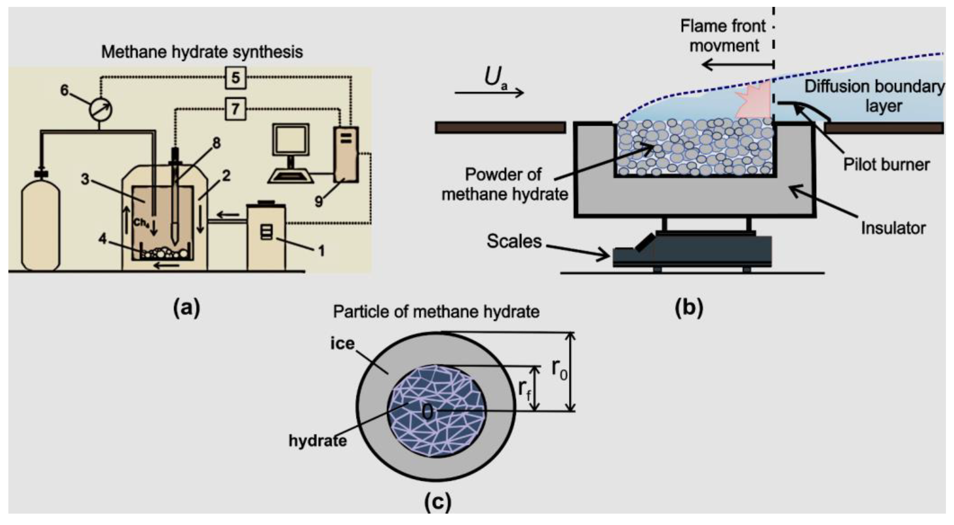
For experimental studies on the dissociation and combustion of methane hydrate, an artificial methane hydrate synthesized in a high-pressure reactor was used (Figure 1a). The method of synthesis of methane hydrate and a detailed description of the experimental setup are given in [24,42]. To accelerate the production of methane hydrate powder, finely crushed ice with a particle diameter of 0.2–0.3 mm was used. Methane gas with purity 99.98% and distilled water were used. The ice powder was placed in a reactor with methane for the synthesis of gas hydrate. In the working chamber of the reactor, the temperature was 274 K, and the methane pressure was 5.5–6 MPa (with an error of 0.5 bar).
After the gas hydrate synthesis, the pressure in the chamber decreased. The powder was removed from the working chamber, crushed again and cooled at the temperature of liquid nitrogen. This scheme was repeated several times until the required amount of gas hydrate was reached. After sieving the powder using sieves, the particle diameter corresponded to a range of values from 0.2 mm to 0.3 mm. The X-ray diffraction served to find that the mass content of ice in the synthesized methane hydrate was approximately 1–2%. The manufactured methane hydrate corresponded to cubic structure I. The elementary cell of the methane hydrate was 2D·6 T·46H2O. The initial mass content of methane in the powder was 9–10%. The scheme of the working installation is shown in Figure 1b. At methane hydrate dissociations, ice and gas were formed. Methane was removed from the powder into the atmosphere, and as a result, the mass of the sample decreased with time. The change in the powder mass was measured using the gravimetric method (scales Vibra AJH 4200 CE). The working area with the gas hydrate was located on the scales. Before the experiment, the methane hydrate powder was extracted from liquid nitrogen and poured into the working area. The temperature of the powder continuously increased due to heat exchange with the ambient medium. The outside air temperature corresponded to 297 K. The external air pressure was 1 bar. When the equilibrium temperature was exceeded (approximately 193 K), the gas hydrate dissociated. A methane–air–water vapor diffusion layer was formed above the powder layer. Combustion occurred with the help of the pilot burner (Figure 1b). When combustion occurred, the edge of the flame front moved from right to left, in the opposite direction from the forced laminar air flow. The powder was located in the working area with dimensions: layer height of 15 mm, width of 40 mm, and length of 50 mm. The dissociation rate of methane hydrate was determined as J = Δm/Δt, where Δm was the change in the powder mass over the dissociation time interval Δt. The experimental error in measuring the dissociation rate of the gas hydrate (taking into account the measurement error of the powder mass and the approximation error of the measurement data) did not exceed 7–8%. It is important to note that J is not a local value, but is defined as an integral value for the entire surface of the powder (there is an inhomogeneous distribution of J on the surface of the layer). The temperature inside the powder layer was measured by thermocouples. The layer surface temperature Ts was measured using a thermal imager (NEC San Instruments). The relative measurement error Ts corresponded to ±1 K. In this case, the error of the thermocouple (after calibration) corresponds to ±0.1 K (the error range of ±1 K is mainly of a methodological nature, since the thermocouple is located inside a porous layer, but not inside a solid particle).
3. Modeling and Experimental Results
3.1. Dissociation of Gas Hydrates at Negative Temperatures
In the quasi-stationary approximation of the isothermal dissociation process, as well as at moderate dissociation rates, the diffusion flow of methane (during dissociation) is assumingly equal to the dissociation rate of methane hydrate. This approximation is justified, since, for methane hydrate particles with a size of 0.1 mm, the time period of dissociation is many times longer than the period of establishing stationary equilibrium. In experiments, particles with a significantly larger size are usually used. In addition, the Lewis number (the ratio of the diffusion coefficient to the thermal conductivity coefficient) is much less than one. As a result, the main resistance for the dissociation process will be the internal dissociation kinetics and diffusion. Since the value of the dimensionless Bio criterion is very low, the temperature inside the particles will be quasi-uniformly distributed. The temperature unevenness occurs only for a thick layer of powder and will be taken into account when solving the equations for heat transfer. Let us consider the problem for the dissociation of a spherical particle (each layer consists of separate spherical particles). The particle packing density is regulated by the porosity, which is determined experimentally based on the mass and volume of the layer. A schematic representation of the dissociation of the methane hydrate sphere is shown in Figure 1c. During dissociation, the thickness of the ice crust layer δ (δ = r0 − rf) increases, and the radius of the non-dissociated sphere of the methane hydrate rf decreases with time.
Taking into account the Darcy equation, the flow of methane Jm through the pores of individual particles will correspond to Equation (1),
where r is the average particle radius for the entire powder, ρm is the density of methane inside the pores, P is the pressure of methane inside the pores, μ is the dynamic viscosity of methane at a set temperature and gas pressure inside the pores, and kD is the permeability coefficient, which is associated with a diameter of pores dp, and with a density of pores σp (a density of pores is number of pores per 1 square meter (1/m2)) by the equation: kD = (F1dp2)/32 [58], where F1 = (σfπdp2)/4 (F1 is a surface part occupied by open pores).
In the approximation of the ideal gas equation (the maximum pressure used in experiments with the gas hydrate dissociation is below 30 bar, which allows using the ideal gas equation), as well as a result of integration, we obtain Equation (2) for the flow of methane Jm through the porous space of spherical particles.
The dissociation rate of methane hydrate can also be expressed using a semi-geometric kinetic expression [20,21] , where the kinetic constant kR = k0·exp(−Ea)/RgT) (k0 is the internal kinetic constant and Ea is the activation energy during the dissociation of methane hydrate). The values of k0 and Ea at negative dissociation temperatures of methane hydrate were obtained experimentally in [24] (k0 = 0.003 kg/(m2Pa·s), Ea = 33.8 kJ/mol). Equating the expressions for the flows taking into account the dissociation kinetics and the filtration rate, we obtain Equation (3)
Let us represent the parameters in the left part of Equation (3) in the form of the parameter λ and solve the resulting quadratic equation with respect to the unknown pressure in the pores Pf, so we obtain the solution in the form of Equation (4) for the methane flow Jm.
Let us represent the dissociation rate of methane hydrate as a degree of transformation of the particle X over time t (A = mH/m0, mH is the current mass of methane hydrate, m0 is the initial mass of methane hydrate, mH = mg/B, B is the initial mass concentration of methane in the gas hydrate (B = 0.14), the initial mass of the particle , and the parameter Changes in the degree of transformation of methane hydrate over time will be written as Equation (5).
The obtained expressions employ the pore parameters (porosity, pore diameter, and pore density) to calculate the methane flow. In other works [20,21,22,29,40,43,45], the porosity of the particles and the ratio of kinetic and filtration resistances are not considered, which prevents the correct dependence of the dissociation rate of gas hydrate on temperature in a wide temperature range from being established (at temperatures below the melting point of ice, including during self-preservation). In order to solve the system of equations, we have developed a special computational code to find the characteristic parameters of the dissociation of gas hydrates, as well as parameters of combustion under quasi-stationary modes. When calculating the temperature field, the difference grid has the first order of approximation for the time step and the second order for the spatial step (the time step was 0.1 s; the maximum number of layers in the powder layer (at the maximum layer height) corresponded to 60 layers). The maximum difference between calculating the powder mass during dissociation of methane hydrate and the experimental data, does not exceed 10%.
The dissociation rate of methane hydrate is inversely proportional to the initial average radius of the particles. To increase the efficiency of storage and transportation of methane hydrate, it is more profitable to produce methane hydrate in the form of large particles when low dissociation rates are realized. For effective combustion of methane hydrate, it is necessary, on the contrary, to use particles of small size, since low rates of methane release can lead to the termination of combustion.
Figure 2 shows the calculated data on the change in the pressure difference in the pores for different values of the average radius of particles in the methane hydrate powder layer. These curves are obtained under the condition of self-preservation, in which the pore size reaches a low value, and the filtration resistance becomes sufficiently high and controls the nature of the decomposition of methane hydrate. For the calculation, the following data are taken: the external air pressure P0 = 1 atm, the pore radius inside the spherical particles rp corresponds to the average pore radius of 0.3 µm (this pore radius is taken in accordance with the data of various works where a high degree of self-preservation is achieved). With the time of dissociation, the degree of transformation A increases.
As follows from Figure 2, the pressure in the pores at the methane hydrate dissociation front varies greatly with time and has a nonlinear character. Pf depends on the initial particle size. The above equations addressed a thin layer of powder, when a quasi-isothermal formulation is acceptable not only for particles, but also for the entire layer, as well as a homogeneous temperature distribution within the layer. For a thick layer and at a high heat flux, a spatially inhomogeneous and non-stationary temperature field will be observed. In this case, it is necessary to simultaneously solve both the equation for heat transfer inside the powder layer and the equation of dissociation of methane hydrate. Let us consider the heat transfer in the powder layer using the effective thermal conductivity coefficient with λef, which takes into account the thermal conductivity of solid particles and methane as well as the porosity of the layer. During the dissociation process, the layer height decreases, which indicates a change in the porosity of the powder over time due to the coalescence of particles. Next, we will vary the λef for numerical solutions of the equations. Let us consider the heat transfer equation in a powder layer in the form of a one-dimensional equation, Equation (6):
where T is the temperature inside the powder layer; t is the dissociation time of methane hydrate; z is the height coordinate of the powder layer; cp is the specific heat capacity of powder particles (taking into account the transformation A, both the heat capacity of ice and the heat capacity of gas hydrate are considered); λef is the effective value of the thermal conductivity coefficient for the entire powder layer; Q is the heat of dissociation of methane hydrate; A is the degree of transformation of a methane hydrate particle; Por. is the porosity in the powder layer, which is defined as Por. = (ρH − ρ)/ρ (ρH is the density of the gas hydrate; and p is the average density of the powder in the layer (ρ = ρH(1 − Por.)). In this formulation, the heat flux along the longitudinal coordinate is neglected (the side walls are considered as heat-insulated with high thermal resistance). The z coordinate changes with the height of the powder layer. Boundary and initial conditions of heat exchange are introduced for the upper surface of the layer. The average density in the powder layer and the degree of transformation are related by the ratio (ρH and ρI are the densities of methane hydrate and ice in a solid particle). For the upper boundary of the powder layer (coordinate z = 0), a boundary condition is introduced, , where Ta is the temperature of the external air, and α is the convective heat transfer coefficient for the gas medium.
For the lower boundary of the powder layer, we write the boundary condition for conductive heat transfer , where λ1w is the thermal conductivity of the heat-insulating material of the wall, δw is the wall thickness, and T0 is the temperature of the outer boundary of the thermal insulation. The heat transfer coefficient α can be related to the gas velocity through the equation for the Nusselt number (), where , , ν is the kinematic viscosity of the gas, λ is the thermal conductivity of the gas, a is the temperature diffusivity, and L is the characteristic longitudinal length of the layer on which the wall boundary layer develops.
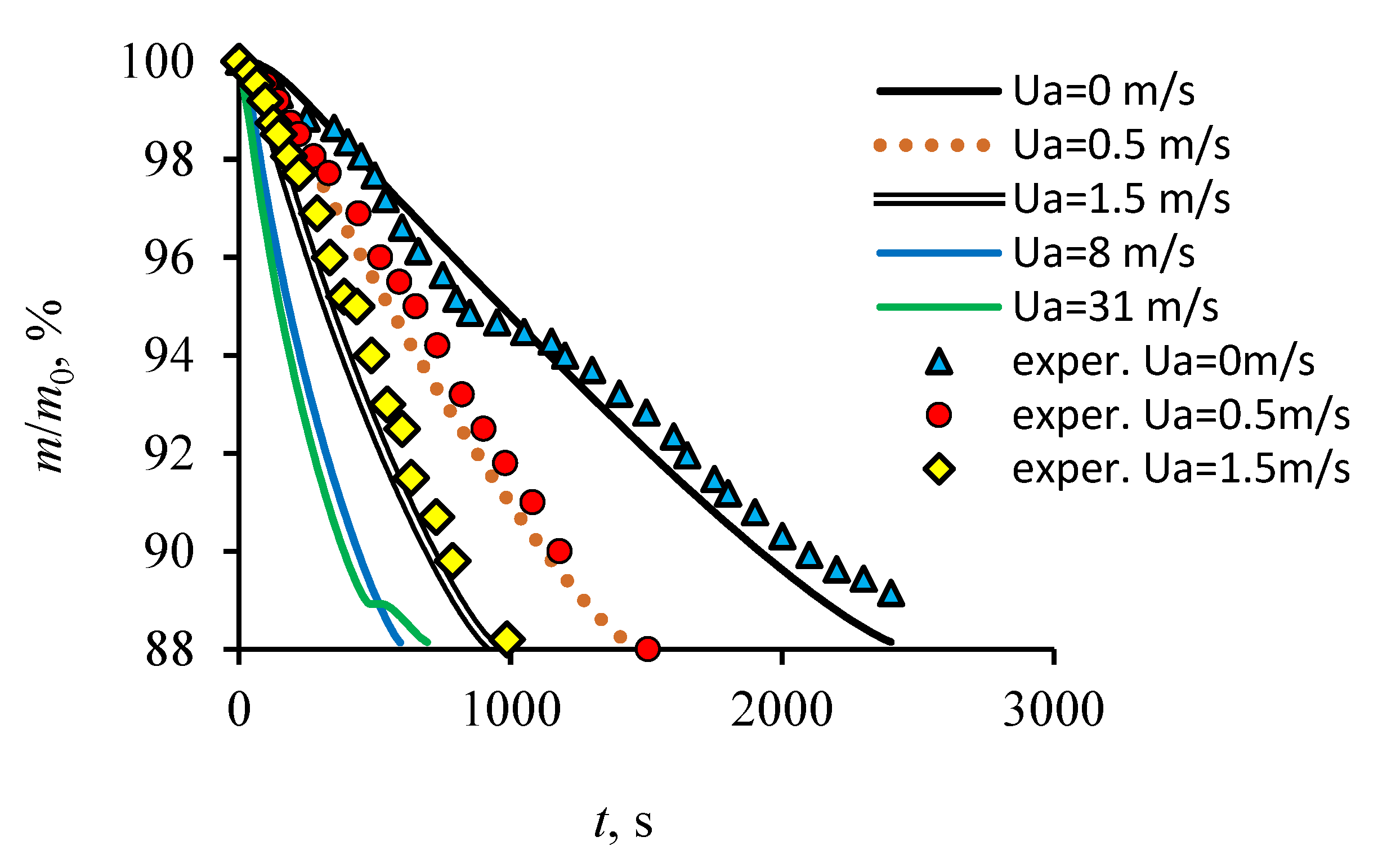
Figure 3 shows calculated and experimental data on the change in the dimensionless mass of the powder with a continuous increase in the temperature of the powder due to heat exchange with the ambient medium (the presence of conductive and convective heat flux). With an increase in the velocity of the laminar forced air flow Ua, the dissociation rate of the gas hydrate Jm increases (the total dissociation time decreases and the slope of the curved lines increases). The increase in Jm is associated with an increase in the heat transfer coefficient α and the heat flux, which is proportional to (Ua)0.5. It should be noted that at Ua = 0 m/s, there is also a gas flow over the surface of the powder layer due to buoyancy, since there is a temperature gradient on the surface. The characteristic value of the convective velocity of the gas U at the characteristic length of the heat exchange section L can be determined (in accordance with the gas buoyancy) by an approximate ratio (without taking into account the forces of viscous friction) (β is the coefficient of thermal expansion of the gas). At high values of Ua (Ua > 6–8 m/s), an increase in the air velocity practically ceases to affect the change in dissociation, i.e., the curves tend to an asymptotic solution. At low heat fluxes (Ua = 0 m/s), the self-preservation site is more prominent. The above equations allow the behavior of methane hydrate dissociation to be predicted, taking into account the air velocity and the thickness of the powder layer.
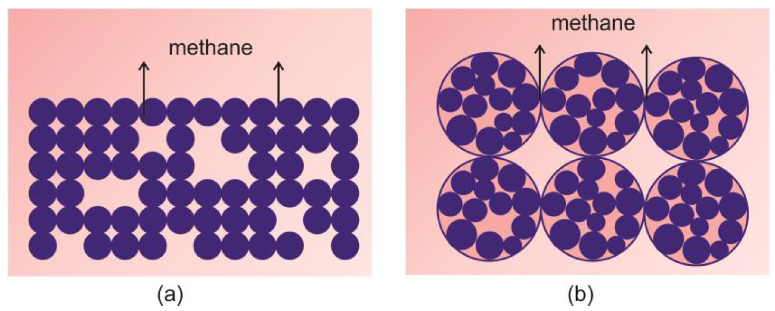
The effective thermal conductivity of the powder layer [58] is usually calculated when the particles are integral solid spheres (Figure 4a). In this case, the effective value of the thermal conductivity coefficient in the powder (λef) can be calculated using Equation (7) [58]:
where λm and λs are the thermal conductivity coefficients of methane and solid particles, and G is the parameter that takes into account the contact surface between the particles. When the powder is poured into the working area, the dimensions of the aggregates, due to the coalescence of particles, change in the range of 0.5–3 mm. Thus, the size of the aggregates is much larger than the particle size of 0.2–0.3 mm. In this case, the packaging of aggregates in the layer (Figure 4b) is fundamentally different from the packaging shown in (Figure 4a).
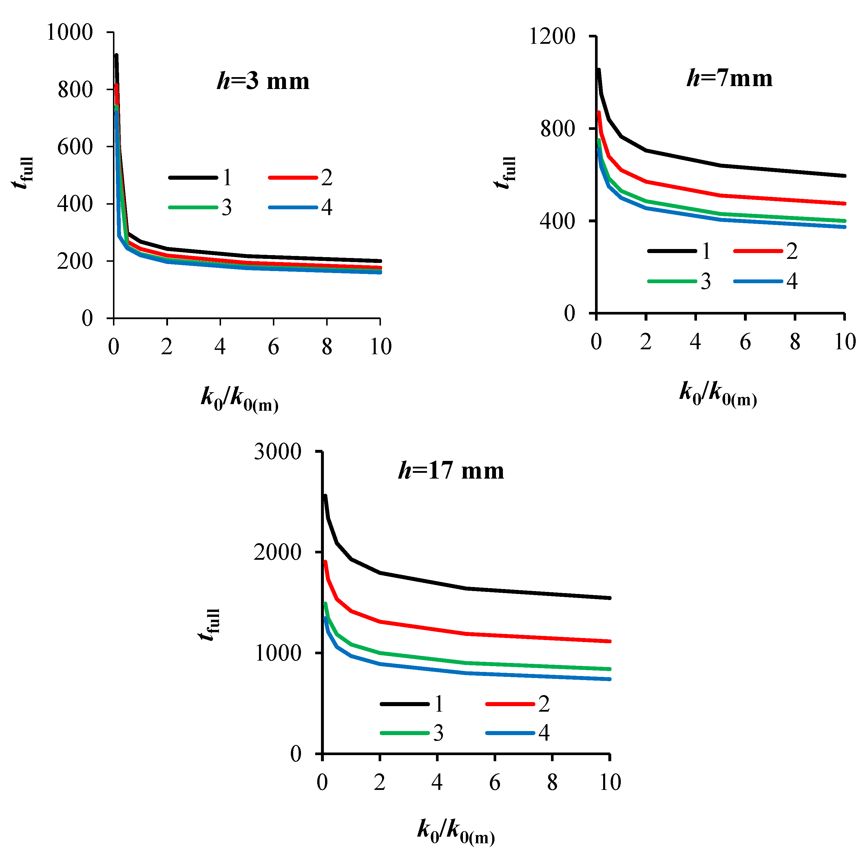
It is obvious that the heating of an integral solid sphere will be faster than for the aggregate consisting of many particles. Given that the thermal conductivity of ice and methane hydrate is higher than that of gas, the heating of a powder layer consisting of aggregates may be slower than for a layer of integral solid spheres (particles). In addition, the porosity is distributed unevenly across the layer, which can also slow down the conductive heat transfer in the layer. With reference to the above, it is important to assess how a decrease in the effective thermal conductivity (due to particle aggregation) will affect the rate of dissociation of methane hydrate. To simplify the analysis, Figure 5 shows the calculated curves for the total dissociation time of methane hydrate tfull. The value of the effective thermal conductivity is varied using the coefficient a, which varies from 1 to 0.1. The calculation results are performed at different thicknesses of the powder layer h; 3, 7, 17 mm.
An increase in the dissociation rate (an increase in k0/k0(m)) at k0/k0(m) > 1 has a weak effect on a decrease in the total dissociation time of the gas hydrate. In this case, the decisive role is played by the thermal resistance of the layer and external heat fluxes. A strong influence of the dissociation kinetics is manifested for small values of k0/k0(m) (k0/k0(m) 1). At very low values of k0/k0(m), the predominant dissociation time corresponds to the maximum deviation of the system from equilibrium. The powder warms up quickly and turns out to be in the region of maximum temperature, which leads to an increase in the heat of dissociation (there is an exponential dependence of the dissociation rate on temperature and a linear dependence on the pressure difference). Therefore, in the specified region (k0/k0(m) 1), there is a strong dependence of the dissociation kinetics on the internal dissociation constant. A small error in the measurement of the activation energy, or in k0, will lead to a significant error in the calculation of the total dissociation time. As mentioned above, high values of k0/k0(m), on the contrary, lead to a weak dependence of the calculation error on the accuracy of determining k0(m). With a thick layer (h = 17 mm), the effect of the thermal conductivity of the layer is maximum. A 10-fold decrease in the effective thermal conductivity of λef1 leads to a more than two-fold increase in tfull. For a thin powder layer (h = 3 mm), the thermal conductivity of the layer has a noticeably weaker effect on the solution at k0/k0(m) > 1.
3.2. Combustion of Methane Hydrate at Dissociation of a Powder Layer
When combustion occurs above the powder layer, the heat flux from the gas phase to the layer increases dozens of times. In addition, the combustion region is located at a distance of several millimeters from the layer surface. As a result, areas with a relatively high temperature may appear near the gas hydrate, which leads to the formation of a high concentration of steam in the combustion region. The presence of an external air flow affects the effective convective heat transfer coefficient, which is calculated both in the previous paragraph using the numbers Nu, Re and Pr. The heat balance in the combustion zone is written as Equation (8),
where τ is the average time of finding the reacting gases in the combustion region; χ is the effective volumetric heat transfer coefficient for a mixture of gases, which takes into account the volumetric heat losses during fuel combustion W·m−3·K−1); nj is the molar concentrations of the gas components (mole·m−3) (superscript 0 refers to the initial composition, i.e., before the combustion reaction); h is the molar enthalpy (J·mole−1), and h0 is the molar enthalpy at the initial gas temperature (T0 = 300 K). Specific enthalpies were determined in accordance with [59]. The initial average temperature on the surface of the powder layer at the occurrence of combustion Ts = 243 K. The relative humidity of the external air corresponded to 30%. The reaction rate at the stationary front was considered in the approximation of an ideal mixing reactor in accordance with [60] (Equation (9)):
where the pre-exponential factor is k0 = 0.883·107 (s−1), and the activation energy is E = 121·103 (J·mole−1), m = m1 + m2 = 1.69.
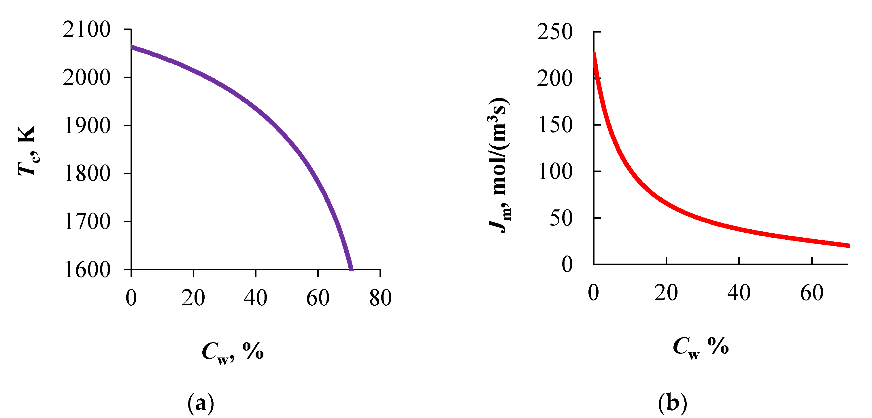
Figure 6a shows the results of modeling the combustion temperature and the methane flow (Figure 6b) with a change in the concentration of water vapor in the combustion region (at the external air velocity Ua = 1 m/s). The methane flow reflects the dissociation rate of methane hydrate. Thus, with an increase in Cw дo of 60–70%, the molar concentration of methane in the mixing layer (methane–air–water vapor) will decrease several times, which can lead to the cessation of combustion.
Experimental data show that the combustion becomes unstable at a high air velocity ((Ua > 1–1.5 m/s), which is associated with both high heat losses and a decrease in the rate of methane entering the combustion zone. The combustion temperature drops by 450 K when the Cw increases from 0 to 70%. The experimental value of the maximum combustion temperature is 1700–1750 K, which corresponds to Cw = 60–65%. These values correlate well both with the calculated curve in Figure 6a and with the results of the work [51,52,55,56].
The effect of the water vapor concentration on the heat flux qf, directed from the combustion region to the upper surface of the powder is shown in Figure 7. When Cw = 55–60% is exceeded, the slope of the curve increases noticeably. An increase in the amount of water vapor leads to a decrease in the combustion temperature and, accordingly, to a drop in the heat flux into the wall. For correct modeling of heat transfer and dissociation rate, it is important to take into account the nonlinear dependence of heat transfer on Cw. The ratio of heat loss qw due to water vapor to the heat flux qf also strongly depends on Cw. The maximum value of qw/qf corresponds to the maximum concentration of water vapor.
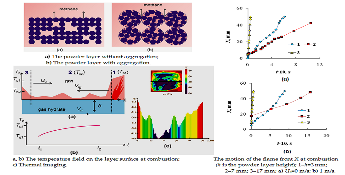
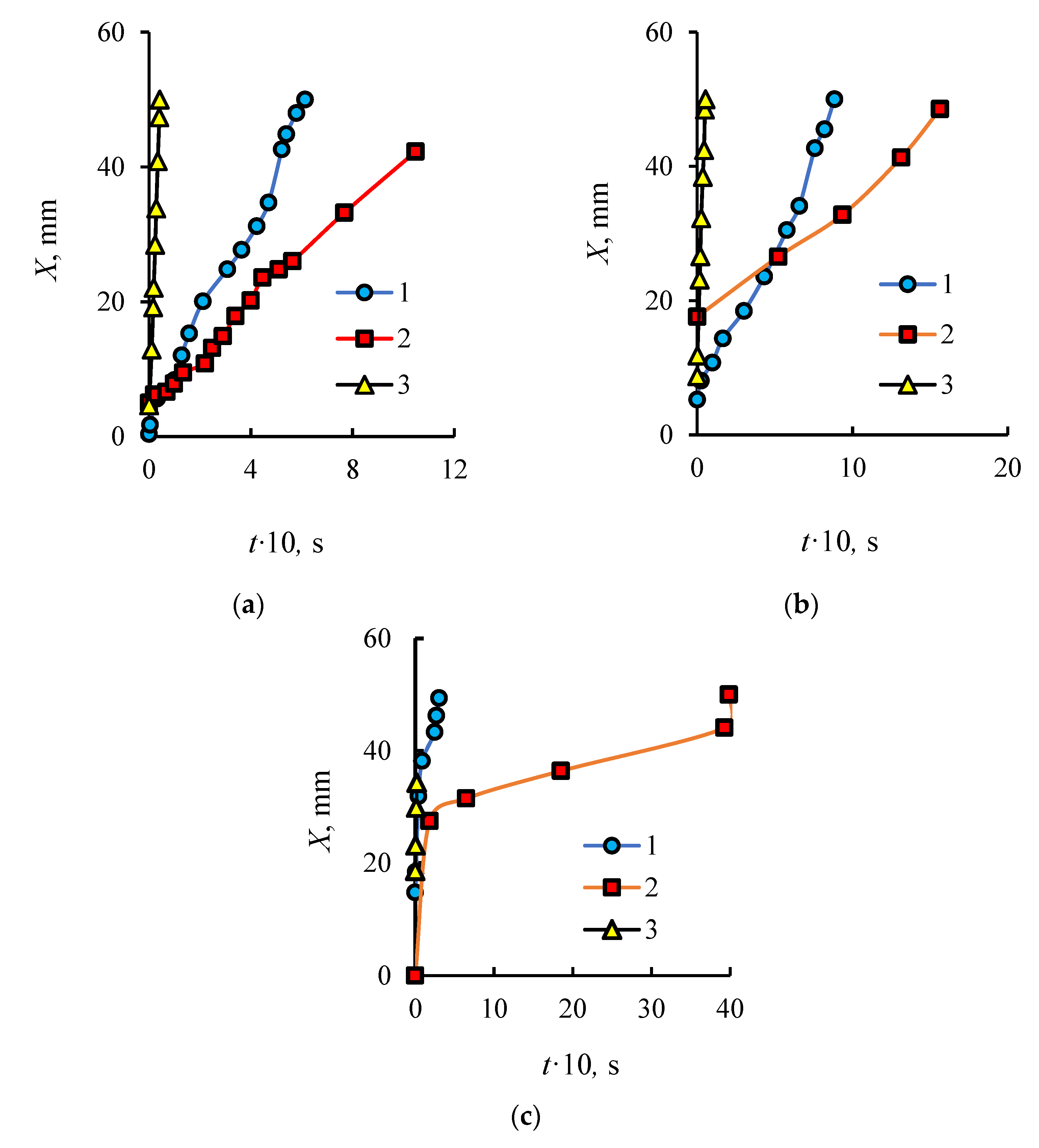
Figure 8 shows the experimental curves of the flame edge motion at different heights of the powder layer h, as well as at different external air velocity Ua. The three re-conducted experiments showed that the qualitative character of the curves remains, although the values of the points somewhat differ (the discrepancies between the curves under identical conditions do not exceed 20–30%). The flame front motion is realized from the rightmost point of the working area to the left (against the air motion) (Figure 1b). When Ua = 0 m/s, all three curves have a quasi-linear character. The linear nature of the curves and the highest velocity of the flame front (Vf) correspond to the thickest layer (h = 17 mm). The ignition, with the help of the pilot burner, for all experiments, begins at the surface temperature of the powder Ts = 233–235 K (in the center of the working area—determined by the measurements of the thermal imager). For lower layer heights h = 3 and 7 mm, the flame front velocity Vfg decreases and there are 2–3 characteristic modes. For example, for curve 2 in Figure 8c, the first mode corresponds to Vf = 0.15 m/s. The flame front velocity of the second mode is equal to Vf = 0.0043 m/s (about 40 times decrease in Vf compared to the first mode).
The third mode corresponds to the velocity Vf = 0.09 m/s (about 20 times growth of Vf in comparison with the second mode). Such a strong and contradictory dependence of the behavior of Vf on the layer height and air velocity is associated with a complex dependence of the dissociation rate of methane hydrate on temperature, as well as on the strong inhomogeneity of the temperature field.
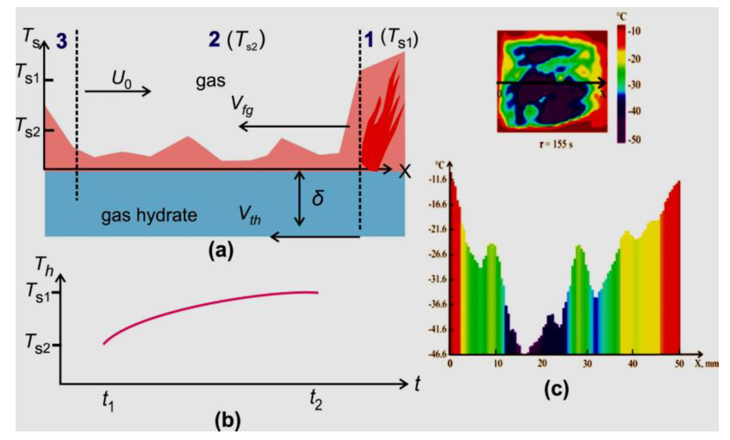
Figure 9c shows thermal imaging measurements of the layer surface before the start of combustion. It can be seen that the temperature field is extremely unevenly distributed. The maximum temperatures always correspond to the side walls of the tank. Three characteristic temperature sections are shown in the schematic Figure 9a. Section 1 corresponds to the area of the beginning of combustion. The combustion front moves above the powder surface at a velocity Vfg. The heat front also moves in the powder layer with the velocity Vth. There is a higher temperature gradient at the boundary of this front. The temperature of the second section (before the combustion front) increases from Ts2 to Ts1 during the time interval t2–t1. As mentioned above, the beginning of combustion is realized at a temperature close to the self-preservation region (238 K). For a thick layer of powder (h = 17 mm), heating inside the layer is realized more slowly (at any velocity Ua), compared with thinner layers.
For all cases, there is both a self-preservation region and an area outside the annealing temperature window at the same time. However, due to the slower heating (q~λΔT/h, the characteristic heating time is th~h, where h is the height of the layer), for a thicker layer, a larger amount of powder is outside the self-preservation region and a higher dissociation rate is achieved (a higher methane flow, both on the layer surface and in the combustion region). This leads to stable combustion and a higher combustion temperature, which provides a higher rate of chemical reaction when the fuel interacts with the oxidizer. Conversely, a decrease in the height of the layer and an increase in the air velocity lead to a faster heating of the powder and to its ingress into the region of a low dissociation rate. As a result, the stability of combustion and the reaction rate decrease. Thus, when simulating combustion gas hydrates, it is important to take into account not only the air velocity, but also the influence of the height of the powder layer, convective and conductive heat flux on the dissociation rate.
4. Conclusions
With the growth of air velocity, the dissociation rate increases as well. For a correct modeling of dissociation, it is important to take into account both convective and conductive heat exchange.
The thermal conductivity of the powder layer and the conductive heat flux can change significantly due to the formation of particle aggregates inside the powder layer, which affects the dissociation rate of methane hydrate.
The air velocity and vapor concentration in the combustion zone strongly affect the combustion temperature, flame stability and the flame front velocity.
An increase in the amount of water vapor leads to a decrease in the combustion temperature and, accordingly, to a drop in the heat flux to the wall. For correct modeling of heat transfer and dissociation rate, it is important to take into account the nonlinear dependence of heat transfer on the concentration of water vapor.
A decrease in the height of the layer and an increase in the air velocity lead to a faster heating of the powder and to its ingress in the self-preservation area. When simulating combustion of gas hydrates, it is important to take into account not only the air velocity, but also the influence of the height of the powder layer, as well as the convective and conductive heat flux on the dissociation rate.
The obtained results may be applied to increase the efficiency of methane hydrate combustion, as well as to develop existing methods for calculating the methane hydrate powder layer, as well as for technologies for degassing combustible gases and their application in the energy sector.
Author Contributions
S.Y.M. and I.G.D. performed experiments related to the gas hydrate dissociation and combustion, modeling the gas hydrate dissociation and combustion. All authors have read and agreed to the published version of the manuscript.
Funding
Experiments and modeling of gas hydrate dissociation were carried out within the framework of the state assignment for the Institute of Thermophysics Siberian Branch, Russian Academy of Sciences; Modeling of combustion was carried out within the framework of the State Assignment Project (no. FWEU-2021-0005) of the Fundamental Research Program of Russian Federation 2021-2030 using the resources of the High-Temperature Circuit Multi-Access Research Center (Minobrnauki of Russia, project no 13.ЦКП.21.0038).
Institutional Review Board Statement
The study was conducted according to the guidelines of the Declaration of Helsinki, and approved by the Institutional Review Board.
Informed Consent Statement
Informed consent was obtained from all subjects involved in the study.
Conflicts of Interest
The authors declare no conflict of interest.
Nomenclature
| A | the degree of transformation of methane hydrate (A = mH/m0) |
| a | the thermal diffusivity |
| C | the mass concentration |
| Cp | the heat capacity |
| E | the activation energy |
| h | the molar enthalpy |
| h | the powder layer height |
| Mr | the molecular weight of gas |
| m | mass |
| n | the molar concentrations of gas components |
| Por | the porosity in the powder layer |
| P | the gas pressure |
| Q | the heat of the methane hydrate dissociation |
| q | the heat flux density |
| Rg | the universal gas constant |
| r | the reaction rate |
| r | the radius of particle |
| t | time |
| tfull | the total dissociation time |
| T | temperature |
| J | gas flow |
| kR | the kinetic constant |
| kD | the permeability coefficient |
| k0 | the kinetic constant refers to methane hydrate at negative temperatures |
| U | the convective gas velocity |
| X | the motion of the flame front |
| z | the transverse coordinate |
| Greek symbols | |
| α | the convective heat transfer coefficient |
| δ | the ice crust layer |
| λ | the thermal conductivity |
| µ | the dynamic viscosity |
| ν | the kinematic viscosity |
| ρ | density |
| σp | the pore density |
| χ | the effective volumetric heat transfer |
| Subscripts | |
| a | air |
| 0 | the outer boundary |
| eq | equilibrium |
| eff | effective |
| f | the reaction front |
| g | gas |
| H | hudrate |
| I | ice |
| m | methane |
| s | the layer surface |
| S | solid |
| w | wall |
| w | water |
References
- Yin, Z.; Linga, P. Methane hydrates: A future clean energy resource. Chin. J. Chem. Eng. 2019, 27, 2026–2036. [Google Scholar] [CrossRef]
- Cui, Y.; Lu, C.; Wu, M.; Peng, Y.; Yao, Y.; Luo, W. Review of exploration and production technology of natural gas hydrate. Adv. Geo Energy Res. 2018, 2, 53–62. [Google Scholar] [CrossRef] [Green Version]
- Chong, Z.R.; Yang, S.H.B.; Babu, P.; Linga, P.; Li, X.-S. Review of natural gas hydrates as an energy resource: Prospects and challenges. Appl. Energy 2016, 162, 1633–1652. [Google Scholar] [CrossRef]
- Lu, S.M. A global survey of gas hydrate development and reserves: Specifically in the marine field. Renew. Sustain. Energy Rev. 2015, 41, 884–900. [Google Scholar] [CrossRef]
- Sloan, E.D., Jr.; Koh, C.A. Clathrate Hydrates of Natural Gases, 3rd ed.; CRC Press: Boca Raton, FL, USA, 2008. [Google Scholar]
- Istomin, V.A.; Yakushev, V.S. Gas Hydrates in Nature; Nedra: Moscow, Russia, 1992. [Google Scholar]
- Sum, A.K.; Koh, C.A.; Sloan, E.D. Developing a comprehensive understanding and model of hydrate in multiphase flow: From laboratory measurements to field applications. Energy Fuels 2012, 26, 4046–4052. [Google Scholar] [CrossRef]
- Xie, Y.; Li, G.; Liu, D.; Liu, N.; Qi, Y.; Liang, D.; Guo, K.; Fan, S. Experimental study on a small scale of gas hydrate cold storage apparatus. Appl. Energy 2010, 87, 3340–3346. [Google Scholar] [CrossRef]
- Javanmardi, J.; Nasrifar, K.; Najibi, S.H.; Moshfeghian, M. Economic evaluation of natural gas hydrate as an alternative for natural gas transportation. Appl. Therm. Eng. 2005, 25, 1708–1723. [Google Scholar] [CrossRef]
- Wang, Y.; Li, X.C.; Li, G.; Zhang, Y.; Li, B.; Chen, Z.Y. Experimental investigation into methane hydrate production during three-dimensional thermal stimulation with five-spot well system. Appl. Energy 2013, 110, 90–97. [Google Scholar] [CrossRef]
- Li, G.; Li, X.-S.; Yang, B.; Duan, L.-P.; Huang, N.-S.; Zhang, Y.; Tang, L.-G. The use of dual horizontal wells in gas production from hydrate accumulations. Appl. Energy 2013, 112, 1303–1310. [Google Scholar] [CrossRef]
- Zhong, D.; Englezos, P. Methane separation from coal mine methane gas by tetra-n-butyl ammonium bromide semiclathrate hydrate formation. Energy Fuels 2012, 26, 2098–2106. [Google Scholar] [CrossRef]
- Lee, Y.; Seo, Y.-J.; Ahn, T.; Lee, J.; Lee, J.X.; Kim, S.-J.; Seo, Y. CH4-Flue gas replacement occurring in sH hydrates and its significance for CH4 recovery and CO2 sequestration. Chem. Eng. J. 2017, 308, 50–58. [Google Scholar] [CrossRef]
- Hu, C.G.; Li, X.-S. Research progress of hydrate-based CO2 separation and capture from gas mixture. RSC Adv. 2014, 4, 18301–18316. [Google Scholar]
- Cai, L.; Pethica, B.A.; Debenedetti, P.G.; Sundaresan, S. Formation of cyclopentane methane binary clathrate hydrate in brine solutions. Chem. Eng. Sci. 2016, 141, 125–132. [Google Scholar] [CrossRef]
- Maslin, M.; Owen, M.; Betts, R.; Day, S.; Jones, T.D.; Ridgwell, A. Gas hydrates: Past and future geohazard? Philos. Trans. A. Math. Phys. Eng. Sci. 2010, 368, 2369–2393. [Google Scholar] [CrossRef] [PubMed]
- Hatzikiriakos, S.G.; Englezos, P. The relationship between global warming and methane gas hydrates in the earth. Chem. Eng. Sci. 1993, 48, 3963–3969. [Google Scholar] [CrossRef]
- Misyura, S.Y.; Manakov, A.Y.; Morozov, V.S.; Nyashina, G.S.; Gaidukova, O.S.; Skiba, S.S.; Volkov, R.S.; Voytkov, I.S. The influence of key parameters on combustion of double gas hydrate. J. Nat. Gas Sci. Eng. 2020, 80, 103396. [Google Scholar] [CrossRef]
- Misyura, S.Y. Developing the environmentally friendly technologies of combustion of gas hydrates. Reducing harmful emissions during combustion. Environ. Pollut. 2020, 265, 114871. [Google Scholar] [CrossRef]
- Clarke, M.; Bishnoi, P.R. Determination of the activation energy and intrinsic rate constant of methane gas hydrate decomposition. Can. J. Chem. Eng. 2001, 79, 143–147. [Google Scholar] [CrossRef]
- Kim, H.C.; Bishnoi, P.R.; Heidemann, R.A.; Rizvi, S.S.H. Kinetics of methane hydrate decomposition. Chem. Eng. Sci. 1987, 42, 1645–1653. [Google Scholar] [CrossRef]
- Vysniauskas, A.; Bishnoi, P. A kinetic study of methane hydrate formation. Chem. Eng. Sci. 1983, 38, 1061–1072. [Google Scholar] [CrossRef]
- Misyura, S.Y. Comparing the dissociation kinetics of various gas hydrates during combustion: Assessment of key factors to improve combustion efficiency. Appl. Energy 2020, 270, 115042. [Google Scholar] [CrossRef]
- Misyura, S.Y. Non-stationary combustion of natural and artificial methane hydrate at heterogeneous dissociation. Energy 2019, 181, 589–602. [Google Scholar] [CrossRef]
- Sun, Y.; Ma, X.; Guo, W.; Jia, R.; Li, B. Numerical simulation of the short- and long-term production behavior of the first offshore gas hydrate production test in the South China Sea. J. Pet. Sci. Eng. 2019, 181, 106196. [Google Scholar] [CrossRef]
- Yu, T.; Guan, G.; Abudula, A. Production performance and numerical investigation of the 2017 offshore methane hydrate production test in the Nankai Trough of Japan. Appl. Energy 2019, 251, 113338. [Google Scholar] [CrossRef]
- Khasanov, M.K.; Rafikova, G.R.; Musakaev, N.G. Mathematical model of carbon dioxide injection into a porous Reservoir saturated with methane and its gas hydrate. Energies 2020, 13, 440. [Google Scholar] [CrossRef] [Green Version]
- Khasanov, M.K.; Musakaev, N.G.; Stolpovsky, M.V.; Kildibaeva, S.R. Mathematical model of decomposition of methane hydrate during the injection of liquid carbon dioxide into a reservoir saturated with methane and its hydrate. Mathematics 2020, 8, 1482. [Google Scholar] [CrossRef]
- Selim, M.S.; Sloan, E.D. Heat and mass transfer during the dissociation of hydrates in porous media. AIChE J. 1989, 35, 1049–1052. [Google Scholar] [CrossRef]
- Kuhs, W.F.; Genov, G.; Staykova, D.K.; Hansen, T. Ice perfection and onset of anomalous preservation of gas hydrates. Phys. Chem. Chem. Phys. 2004, 6, 4917–4920. [Google Scholar] [CrossRef]
- Falenty, A.; Kuhs, W.F. Self-preservation of CO2 gas hydrates-surface microstructure and ice perfection. J. Phys. Chem. B 2009, 113, 5975–5988. [Google Scholar] [CrossRef]
- Nguyen, A.H.; Koc, M.A.; Shepherd, T.D.; Molinero, V. Structure of the ice-clathrate interface. J. Phys. Chem. C 2015, 119, 4104–4117. [Google Scholar] [CrossRef]
- Takeya, S.; Uchida, T.; Nagao, J.; Ohmura, R.; Shimada, W.; Kamata, Y.; Ebinuma, T.; Narita, H. Particle size effect of CH4 hydrate for self-preservation. Chem. Eng. Sci. 2005, 60, 1383–1387. [Google Scholar] [CrossRef]
- Misyura, S.Y. Dissociation of various gas hydrates (methane hydrate, double gas hydrates of methane-propane and methane-isopropanol) during combustion: Assessing the combustion efficiency. Energy 2020, 206, 118120. [Google Scholar] [CrossRef]
- Sato, H.; Sakamoto, H.; Ogino, S.; Mimachi, H.; Kinoshita, T.; Iwasaki, T.; Sano, K.; Ohgaki, K. Self-preservation of methane hydrate revealed immediately below the eutectic temperature of the mother electrolyte solution. Chem. Eng. Sci. 2013, 91, 86–89. [Google Scholar] [CrossRef]
- Takeya, S.; Ripmeester, J.A. Anomalous preservation of CH4 hydrate and its dependence on the morphology hexagonal of ice. ChemPhysChem 2010, 11, 70–73. [Google Scholar] [CrossRef] [Green Version]
- Zhang, G.; Rogers, R.E. Ultra-stability of gas hydrates at 1 atm and 268.2 K. Chem. Eng. Sci. 2008, 63, 2066–2074. [Google Scholar] [CrossRef]
- Shimada, W.; Takeya, S.; Kamata, Y.; Uchida, T.; Nagao, J.; Ebinuma, T.; Narita, H. Texture change of ice on anomalously preserved methane clathrate hydrate. J. Phys. Chem. B 2005, 109, 5802–5807. [Google Scholar] [CrossRef]
- Misyura, S.Y.; Donskoy, I.G. Dissociation of natural and artificial gas hydrate. Chem. Eng. Sci. 2016, 148, 65–77. [Google Scholar] [CrossRef]
- Crank, J. The Mathematics of Diffusion, 2nd ed.; Oxford University Press: Oxford, UK, 1975; pp. 89–103. [Google Scholar]
- Misyura, S.Y.; Donskoy, I.G. Dissociation kinetics of methane hydrate and CO2 hydrate for different granular composition. Fuel 2020, 262, 116614. [Google Scholar] [CrossRef]
- Misyura, S.Y.; Donskoy, I.G. Ways to improve the efficiency of carbon dioxide utilization and gas hydrate storage at low temperatures. J. CO2 Util. 2019, 34, 313–324. [Google Scholar] [CrossRef]
- Vlasov, V.A. Diffusion model of gas hydrate dissociation into ice and gas: Simulation of the self-preservation effect. Int. J. Heat Mass Transf. 2016, 102, 631–636. [Google Scholar] [CrossRef]
- Misyura, S.Y. The influence of porosity and structural parameters on different kinds of gas hydrate dissociation. Sci. Rep. 2016, 6, 30324. [Google Scholar] [CrossRef] [PubMed] [Green Version]
- Hassanpouryouzband, A.; Joonaki, E.; Farahani, M.V.; Takeya, S.; Ruppel, C.; Yang, J.; English, N.J.; Schicks, J.M.; Edlmann, K.; Mehrabian, H.; et al. Gas hydrates in sustainable chemistry. Chem. Soc. Rev. 2020, 49, 5225–5309. [Google Scholar] [CrossRef] [PubMed]
- Misyura, S.Y. Effect of heat transfer on the kinetics of methane hydrate dissociation. Chem. Phys. Lett. 2013, 583, 34–37. [Google Scholar] [CrossRef]
- Chen, X.R.; Li, X.S.; Chen, Z.Y.; Zhang, Y.; Yan, K.F.; Lv, Q.-N. Experimental investigation into the combustion characteristics of propane hydrates in porous media. Energies 2015, 8, 1242–1255. [Google Scholar] [CrossRef] [Green Version]
- Maruyama, Y.; Yokomori, T.; Ohmura, R.; Ueda, T. Flame spreading over combustible hydrate in a laminar boundary layer. In Proceedings of the 7th International Conference on Gas Hydrate, Edinburgh, UK, 17–21 July 2011. [Google Scholar]
- Maruyama, Y.; Fuse, M.J.; Yokomori, T.; Ohmura, R.; Watanabe, S.; Iwasaki, T.; Iwabuchi, W.; Ueda, T. Experimental investigation of flame spreading over pure methane hydrate in a laminar boundary layer. Proc. Combust. Inst. 2013, 34, 2131–2138. [Google Scholar] [CrossRef]
- Nakamura, Y.; Katsuki, R.; Yokomori, T.; Ohmura, R.; Takahashi, M.; Iwasaki, T.; Uchida, K.; Ueda, T. Combustion characteristics of methane hydrate in a laminar boundary layer. Energy Fuels 2009, 23, 1445–1449. [Google Scholar] [CrossRef]
- Chien, Y.-C.; Dunn-Rankin, D. Combustion characteristics of methane hydrate flames. Energies 2019, 12, 1939. [Google Scholar] [CrossRef] [Green Version]
- Wu, F.H.; Padilla, R.E.; Dunn-Rankin, D.; Chen, G.B.; Chao, Y.C. Thermal structure of methane hydrate fueled flames. Proc. Combust. Inst. 2017, 36, 4391–4398. [Google Scholar] [CrossRef]
- Yoshioka, T.; Yamamoto, Y.; Yokomori, T.; Ohmura, R.; Ueda, T. Experimental study on combustion of a methane hydrate sphere. Exp. Fluids 2015, 56, 192. [Google Scholar] [CrossRef]
- Cui, G.; Wang, S.; Dong, Z.; Xing, X.; Shan, T.; Li, Z. Effects of the diameter and the initial center temperature on the combustion characteristics of methane hydrate spheres. Appl. Energy 2020, 257, 114058. [Google Scholar] [CrossRef]
- Bar-Kohany, T.; Sirignano, W.A. Transient combustion of a methane-hydrate sphere. Combust. Flame 2016, 163, 284–300. [Google Scholar] [CrossRef]
- Dagan, Y.; Bar-Kohany, T. Flame propagation through three-phase methane-hydrate particles. Combust. Flame 2018, 193, 25–35. [Google Scholar] [CrossRef]
- Cui, G.; Dong, Z.; Wang, S.; Xing, X.; Shan, T.; Li, Z. Effect of the water on the flame characteristics of methane hydrate combustion. Appl. Energy 2020, 259, 114205. [Google Scholar] [CrossRef]
- Aerov, M.E.; Todes, O.M.; Narinsky, D.A. Apparatuses with the Steady Grain Layer: Hydraulic and Thermal Fundamentals of Operation; Khimiya: Saint Petersburg, Russia, 1979. [Google Scholar]
- Glushko, V.P. Thermodynamic and Thermophysical Properties of Combustion Products; VINITY AS USSR: Moscow, Russia, 1971; Volume 5. [Google Scholar]
- Snegirev, A.Y. Perfectly stirred reactor model to evaluate extinction of diffusion flame. Combust. Flame 2015, 162, 3622–3631. [Google Scholar] [CrossRef]
Figure 1.
(a) Methane hydrate powder synthesis scheme: 1, coolant temperature meter; 2, heat exchanger for cooling the reactor working chamber; 3, high-pressure reactor working chamber; 4, methane hydrate powder; 5, 6, devices for measuring and adjusting the gas (methane) pressure; 7, thermocouple for measuring the temperature in the working chamber; 8, temperature controller; 9, PC; (b) scheme of the working unit for studying the dissociation of the methane hydrate powder layer and its combustion; (c) a two-layer dissociation scheme of a spherical methane hydrate particle (rf is the radius of the methane hydrate sphere and r0 is the initial radius of the particle).

Figure 2.
The methane pressure Pf on the reaction front in the dimensionless form (Pf − P0)/(Peq − P0); depending on the degree of transformation, A at changes in the initial average radius of the particles in the powder layer r0 (powder temperature of 260 K).
Figure 2.
The methane pressure Pf on the reaction front in the dimensionless form (Pf − P0)/(Peq − P0); depending on the degree of transformation, A at changes in the initial average radius of the particles in the powder layer r0 (powder temperature of 260 K).

Figure 3.
The change in the mass of methane hydrate during dissociation at different values of the velocity Ua (Ua is the velocity of the external air (Figure 1b), the height of the powder layer is 18 mm, the average diameter of the particles is 0.2–0.3 mm, and the porosity of the powder is 50%).
Figure 3.
The change in the mass of methane hydrate during dissociation at different values of the velocity Ua (Ua is the velocity of the external air (Figure 1b), the height of the powder layer is 18 mm, the average diameter of the particles is 0.2–0.3 mm, and the porosity of the powder is 50%).

Figure 4.
(a) The location of the particles in the powder layer; (b) the location of the particle aggregates in the powder layer.
Figure 4.
(a) The location of the particles in the powder layer; (b) the location of the particle aggregates in the powder layer.

Figure 5.
The dependence of the total dissociation time of methane hydrate tfull on the ratio k0/k0(m) and with a change in the thermal conductivity of the powder layer λef (the kinetic constant k0(m) = 0.003 kg/(m2Pa·s) refers to methane hydrate at negative temperatures [41]; the effective thermal conductivity of the layer is defined as λef1 = aλef; at a = 1, λef1 = λef, in this case, the effective thermal conductivity of the layer is calculated in accordance with Equation (7)): 1 (black)–a = 0.1, 2 (red)–a = 0.2, 3 (green)–a = 0.5, 4 (blue)–a = 1.

Figure 6.
(a) Dependence of the maximum combustion temperature on the concentration of water vapor in the combustion region (Ua = 1 m/s); (b) molar methane flow depending on the concentration of water vapor (Ua = 1 m/s).
Figure 6.
(a) Dependence of the maximum combustion temperature on the concentration of water vapor in the combustion region (Ua = 1 m/s); (b) molar methane flow depending on the concentration of water vapor (Ua = 1 m/s).

Figure 7.
The dependence of the heat flux density qf on the concentration of water vapor Cw (Ua = 1 m/s. qf, heat flux in the direction from the combustion zone to the surface of the methane hydrate layer); the dependence of heat losses (qw/qf) on the concentration of water vapor in the combustion region (qw, heat loss associated with water vapor in the combustion region).

Figure 8.
The motion of the flame front X during combustion of methane hydrate at different heights h of the powder layer and at changes in the external air velocity Ua (1 (blue)—h = 3 mm; 2 (red)—h = 7 mm; 3 (yellow)—h = 17 mm; (a) Ua = 0 m/s; (b) Ua = 0.3 m/s; (c) Ua = 1 m/s.
Figure 8.
The motion of the flame front X during combustion of methane hydrate at different heights h of the powder layer and at changes in the external air velocity Ua (1 (blue)—h = 3 mm; 2 (red)—h = 7 mm; 3 (yellow)—h = 17 mm; (a) Ua = 0 m/s; (b) Ua = 0.3 m/s; (c) Ua = 1 m/s.

Figure 9.
(a) Changes in the temperature field on the layer surface (three characteristic areas); (b) changes in the layer surface temperature over time at combustion; (c) thermal imaging measurements of the temperature on the layer surface (top view and cross section).
Figure 9.
(a) Changes in the temperature field on the layer surface (three characteristic areas); (b) changes in the layer surface temperature over time at combustion; (c) thermal imaging measurements of the temperature on the layer surface (top view and cross section).

Publisher’s Note: MDPI stays neutral with regard to jurisdictional claims in published maps and institutional affiliations. |
© 2021 by the authors. Licensee MDPI, Basel, Switzerland. This article is an open access article distributed under the terms and conditions of the Creative Commons Attribution (CC BY) license (https://creativecommons.org/licenses/by/4.0/).
Share and Cite
MDPI and ACS Style
Misyura, S.Y.; Donskoy, I.G. Dissociation and Combustion of a Layer of Methane Hydrate Powder: Ways to Increase the Efficiency of Combustion and Degassing. Energies 2021, 14, 4855. https://0-doi-org.brum.beds.ac.uk/10.3390/en14164855
AMA Style
Misyura SY, Donskoy IG. Dissociation and Combustion of a Layer of Methane Hydrate Powder: Ways to Increase the Efficiency of Combustion and Degassing. Energies. 2021; 14(16):4855. https://0-doi-org.brum.beds.ac.uk/10.3390/en14164855
Chicago/Turabian StyleMisyura, Sergey Y., and Igor G. Donskoy. 2021. "Dissociation and Combustion of a Layer of Methane Hydrate Powder: Ways to Increase the Efficiency of Combustion and Degassing" Energies 14, no. 16: 4855. https://0-doi-org.brum.beds.ac.uk/10.3390/en14164855
Note that from the first issue of 2016, this journal uses article numbers instead of page numbers. See further details here.