
Operation Method of a Load Test Device Using an Energy Storage System for Site Acceptance Test of a Fire-Fighting Emergency Generator


Nonsan Interdisciplinary & Creative Studies Campus121, Daehak-ro, Nonsan-si 32992, Chungcheongnam-do, Korea
*
Author to whom correspondence should be addressed.
Energies 2021, 14(17), 5395; https://0-doi-org.brum.beds.ac.uk/10.3390/en14175395
Submission received: 21 July 2021
/
Revised: 18 August 2021
/
Accepted: 25 August 2021
/
Published: 30 August 2021
(This article belongs to the Topic Optimisation, Optimal Control and Nonlinear Dynamics in Electrical Power, Energy Storage and Renewable Energy Systems)
Abstract
:Emergency generators are important facilities that supply emergency power to fire-fighting facilities in the event of a power outage. Accordingly, a load test of the emergency generator should be performed by cutting off the power source of the fire-fighting target in order to accurately confirm the performance and condition of the emergency generator in normal circumstances. However, the test has usually been carried out without loads due to serious problems, which are caused by a shutdown of the power source for the load test of emergency generators, such as the shutdown of emergency load, etc. In order to overcome these problems, this paper proposes an operation method and algorithm of a load test device using ESS, which can conform to characteristics of emergency loads installed in fire-fighting targets by interconnecting it with the emergency generator. In addition, this paper performs a modeling of an emergency power system using PSCAD/EMTDC, and then this paper confirms the usefulness of the proposed method and operation algorithm of the load test device using ESS.
1. Introduction
An emergency generator for fire-fighting is a key piece of equipment to supply power sources in fire-fighting facilities, which protect property and humans in case of fire accidents. The relevant statutes stipulate that an emergency generator should be installed on buildings larger than a certain size and that a load test should be carried out [1,2,3,4]. The load test of an emergency generator is to switch the automatic transfer switch (ATS) to the emergency power system by shutting down the power supply and to verify that the performance and state of the emergency generator are intact by operating emergency load for a certain period of time [5]. However, since the load test of an emergency generator requires a shutdown of the power supply, the power supply to the general load can be suspended and the electric power system is likely to be damaged due to blackout and reversal, so the no-load test for emergency generator has been performed in general. This not only can violate relevant statutes, but also can cause serious damage to the reliability of fire-fighting facilities that protect people and property in an emergency, such as a fire situation.
Therefore, a method for an on-site load test of an emergency generator is required [6]. Accordingly, in order to overcome these problems, this paper proposes a field load test method and operation algorithm of a load test generator without shutdown of the power supply. Specifically, by interconnecting the emergency generator and energy storage system (ESS), it is a field load test method and operation algorithm that can evaluate the performance and state of the emergency generator by interconnecting the emergency generator and performing charging mode of the ESS with the same characteristic of emergency load. In addition, this paper performs the modeling of an emergency power system that is composed of an emergency generator, emergency load, and ESS load test device using a power system computer-aided design/electromagnetic transients including DC (PSCAD/EMTDC) program, and the simulation is performed to confirm the usefulness of the proposed operation algorithm for the field load test and ESS load test device.
2. Operation Characteristics of Field Load Test for Fire-Fighting Emergency Generator
This chapter presents problems that are caused by the no-load test for emergency generator, and operation characteristics of the field load test by confirming the installation and operation status of emergency generators in Korea.
2.1. Problems of the Field Load Test for Emergency Generator
According to the investigation conducted by the Seoul Institute, the total capacity of emergency generators in domestic use is about 25 GW, which is categorized into 78,000 units; it mostly used for fire-fighting in combination [7]. Fire-fighting emergency generators are important facilities that supply power to emergency load, such as fire-fighting facilities that protect property and humans in case of fire accidents. Therefore, under the “Technical Guideline for the Selection and Installation of emergency generator”, Korean law on electrical engineering, a load operation test should be conducted for at least 30 min at the maximum possible load installed on the secondary side of the emergency generator. In addition, law on fire-fighting stipulates that it is necessary to verify that inspection is carried out by using the load operation test [8].
However, as the load test of the emergency generator has to shut down the power supply, there is a possibility of serious problems, such as interruption of power supply to general loads, damage to low voltage electric machines due to blackout and reversal, and suspension of emergency loads at hospitals using emergency medical equipment. For this reason, the performance and state of emergency generators are checked by visual inspection and no-load test to check only the mechanical defects, such as leakages of water and oil. The no-load test of the emergency generator can adversely affect the diesel engine, a key component of the generator, which can cause exhaust gas to flow back and damage the air supply system, and it can result in problems due to sticking debris and foreign substances of fuel inside the cylinder by incomplete combustion. Since these problems can cause abnormal phenomena, such as engine shutdown due to sudden variations of frequency and voltage in the case of generator operation, advanced countries, including the United States, do not recognize no-load tests and stipulates periodically performing the load test of emergency generators with actual load. Accordingly, the National Fire Prevention Association (NFPA) requires more than 30 percent for the load test as a regulation in the NFPA code [9,10]. On the one hand, according to a survey conducted by the Korea Electrical Engineers Association and Ministry of Trade, Industry, and Energy, 60% of emergency generators were in an inoperable state, with the no-load test pointed out as a major cause, at the time of circulatory blackout that occurred in Korea in 2011, and less than 7% were tested for performance and state by load operation [11,12]. Since not only can this be in violation of relevant legislation, but it can also seriously damage the reliability of fire-fighting facilities protecting lives and property in emergency situations, such as fires, the field load test method that can check an emergency generator’s performance and state is required.
2.2. Operation Characteristics of Field Load Test for Emergency Generator
The output capacity of an emergency power supply is calculated based on the total input capacity of all loads installed in the emergency power facility and operated simultaneously, and the output voltage above the minimum input voltage of load should be maintained even when the load with the largest starting current is operated. In addition, a tolerance to withstand short-term over-current should be endurable, even when the load with the largest input capacity is finally operated. On the one hand, an emergency load of the emergency power system is classified as ‘fire-fighting load’ (fire-fighting facility load), which is the electric load of fire-fighting, fire prevention, evacuation, and fire extinguishing facility, and the load other than the fire-fighting load is classified as ‘emergency load’ (general facility load).
Most of the emergency generators for fire-fighting are combined-use generators that supply emergency power to the fire-fighting facility load and the general load facility when the power supply is interrupted. The general facility loads consist of water supply pumps, street lamps, and other related equipment loads, and the fire-fighting facility loads consist of fire-fighting pumps, ventilation fans, and other fire-fighting-related facilities. In addition, the emergency power usage time of fire-fighting facility load has to be supplied within 20, 40, 60 min, or more, depending on the size of the building.
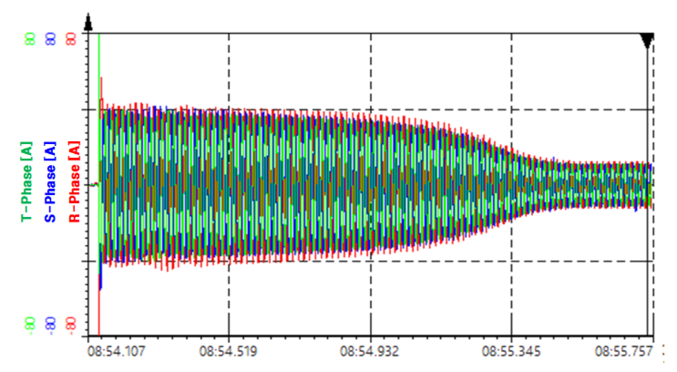
Therefore, it can be seen that the proportion of power capacity for fire-fighting in an emergency generator is quite large. Loads with a large starting current at fire-fighting facility loads are the pumps and ventilation fans that use induction motors. When a power supply is blacked out during a fire accident, the induction motor load with a large starting current and emergency load are operated simultaneously. As shown in Figure 1, the induction motor load has a feature that power factor is rapidly reduced due to the large starting current at start-up, resulting in a huge apparent power [13]. At this time, in the emergency generator, as over-current flows increase due to instantaneous capacity, the possibility of the generator being stopped or failing to start is very high. Hence, it must be considered in the load test of the emergency generator.
Moreover, when a fire extinguishing is carried out by the fire brigade due to failure to extinguish the fire with its own fire-fighting facilities in the worst fire situation, the usage time and capacity of emergency power are increased as the fire brigade uses fire extinguishing facilities (emergency socket, etc.). Therefore, the capacity of emergency power should be calculated by considering a sufficient margin, and the performance and state of the generator should be checked through periodic load test.
3. Operation Algorithm of Load Test Device Using ESS for Fire-Fighting Emergency Generator
In order to improve a method of performance test for the emergency generator without loads, this chapter proposes a novel method of field load test and operation algorithm, which can carry out the test for performance and condition of the emergency generator by connecting ESS to the emergency generator without blackout of the customer.
3.1. Operation Characteristics of Field Load Test for Emergency Generator
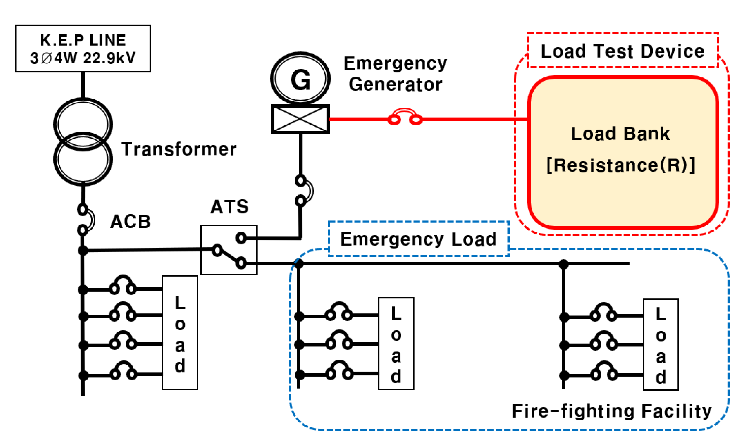
The existing emergency load test method is performed using a load test device (Load Bank) consisting of a load resistance (R), as shown in Figure 2.
Here, when the emergency generator is operated using a general load bank, it not only does not reflect the feature of fire-fighting facility load where current rapidly rises at start-up, but also has a problem of wasting energy by exhausting the generated power. On the one hand, it is possible to use a load test device to which inductive load is applied, but, due to its high cost, it is partially used for research purposes. In addition, a method (back-to-back system) of connecting a power conversion system (PCS) to the power substation to carry out load test of an emergency generator can be considered, as shown in Figure 3 [13,14].
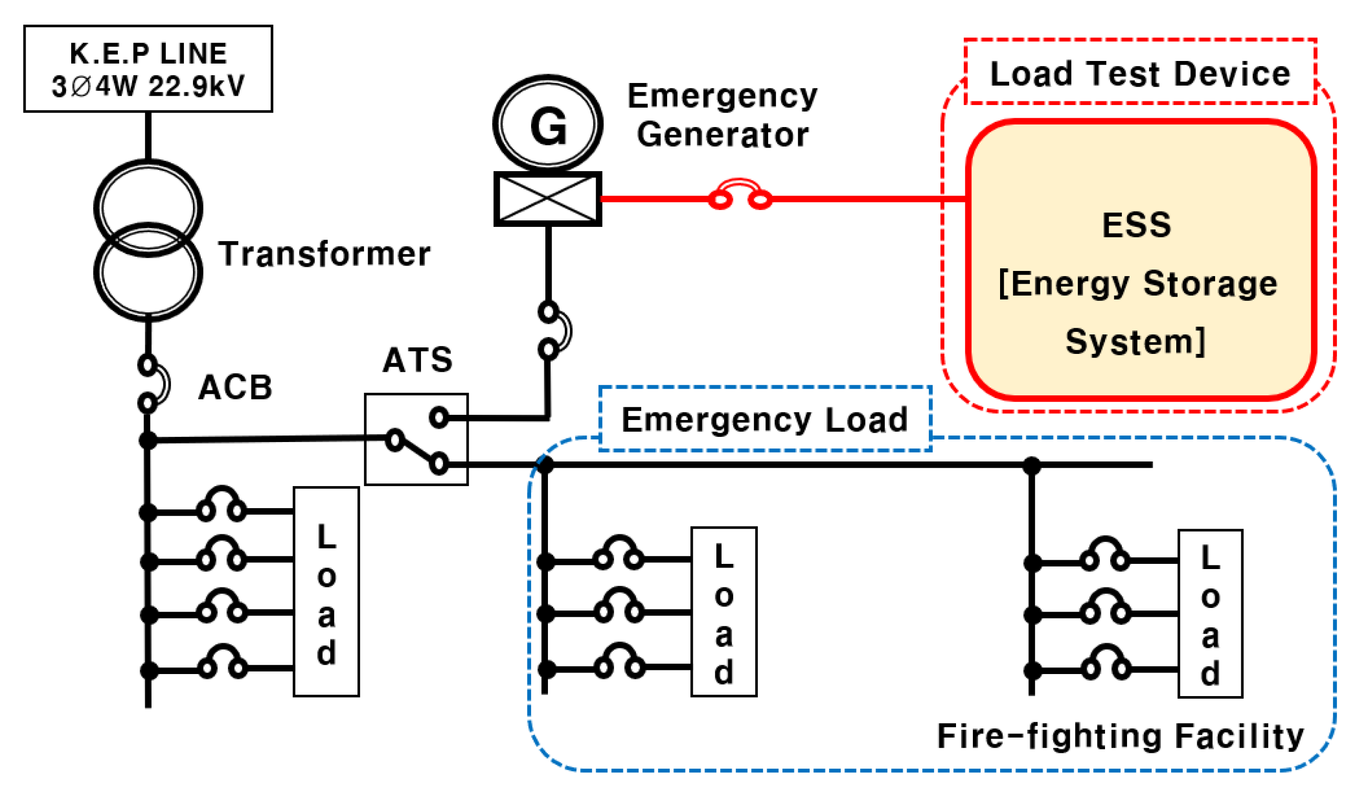
However, it is difficult to apply back-to-back PCS at most sites because there is no spare high-capacity circuit breaker to connect back-to-back PCS to the power substation, so the power supply should be cut off, and a protection co-operation problem about an accident might occur during emergency generator testing. Therefore, as shown in Figure 4, to improve the above problems and prevent secondary damage caused by blackout, this paper proposes the load test method that can check the performance and state of the emergency generator without a shutdown of power supply by using ESS that is based on the power capacity of the emergency loads [15]. Specifically, it is a device that can test the performance and state of the emergency generator by connecting the emergency generator to ESS, and ESS performs the charging operation in the same way as operation characteristics of the emergency load.
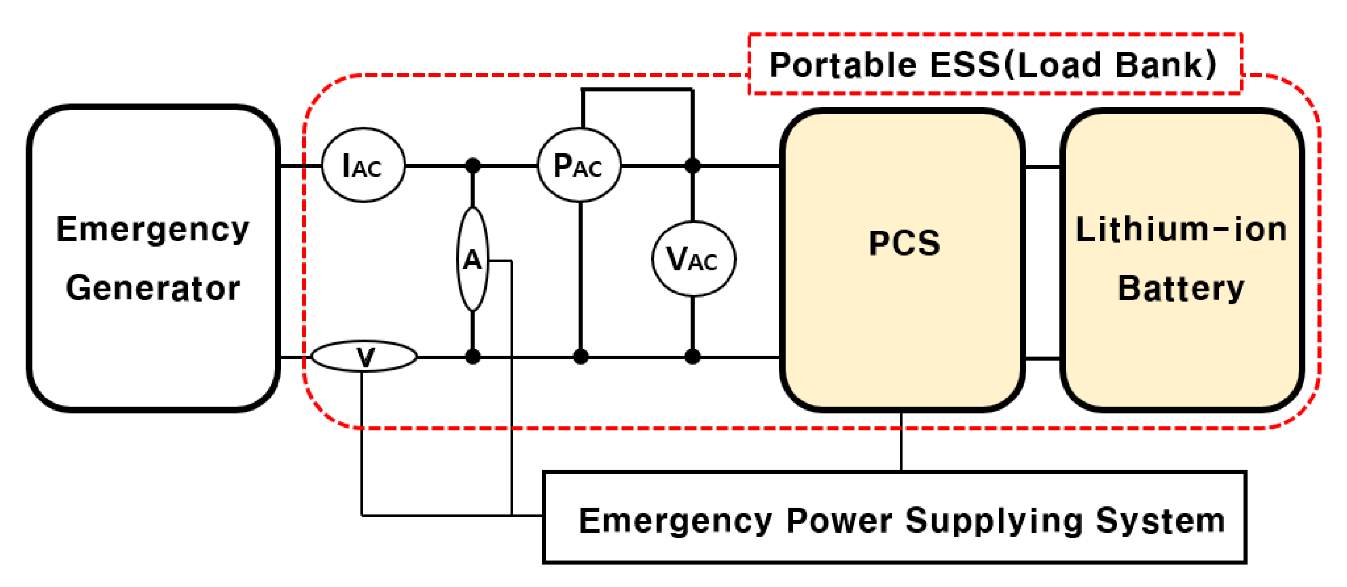
Figure 5 shows the composition of the ESS load test device suggested above. Here, power factor decreases due to a rapid increase in the starting current of fire-fighting facility load and is compensated by a control function of reactive power, and a lithium-ion battery performs the role of emergency load, and the performance and state of the emergency generator can be checked by a measuring instrument. Although the energy storage method of the load test device using ESS for emergency generators can be considered as compressed air, flywheel, lead-acid battery, and so on, the most commonly used Li-ion batteries in recent years have a power conversion efficiency of about 96%, which is superior to other methods (flywheel: 90%, redox flow battery: 70%, and sodium–sulfur battery: 78%), and they have fast response characteristics, such that they can be charged in a short-term way within 15 min [16]. In addition, because the Li-ion batteries have the advantages of easy commercialization and expansion, eco-friendliness, and simple scalability according to required capacity, this paper assumes that the Li-ion batteries are adopted in the load test device using ESS.
3.2. Operation Algorithm of Load Test Device Using ESS
Based on the field load test method of the emergency generator proposed in this paper, the operation algorithm of the ESS load test device that can check the performance and state of an emergency generator by ESS performing a charging operation in the same way as operation characteristics of emergency load is specifically presented as follows:
STEP 1: Based on the emergency generator capacity bill, the capacity is calculated by dividing the emergency load into the fire-fighting induction motor load (ventilation fans () or pumps ()) which has the largest starting capacity and general facility load (). In other words, after calculating active power and reactive power of total emergency load by using Equations (1) and (2), the total rated capacity () of emergency load is calculated using Equation (3). Here, the final output of the emergency generator is calculated by considering the operational efficiency of each emergency load based on the manufacturer’s data sheet.
where, : the total rated capacity of emergency load (kVA), : the total active power of emergency load (kW), : the total reactive power of emergency load (kVar), : the operational efficiency of emergency load (%) (electric lamp, electric heating: 100%, pump: 80~90%).
STEP 2: Fire-fighting ventilation fans () and pumps (), of which power factor decreases due to an increase in sudden current during starting of emergency load and apparent power increases, apply a constant multiple (7.2) of rated capacity (kW) for a direct on-line starting method. In the case of the Y- starting method, the load capacity at starting (kVA) is calculated, multiplying direct on-line starting capacity by starting coefficient () according to Equations (4) and (5).
where, : the apparent power during starting (kVA), : the starting kVA (7.2) per 1 kW of fire-fighting facility load, : starting coefficient (direct on-line starting: 1.0, Y- starting: 0.667).
STEP 3: Starting with the creating time of general facility load (), the making time of fire-fighting fans () and pumps () are 5 s and 10 s. In addition, the start-up time () of fire-fighting facility load is calculated according to Equation (6). A ventilation fan () and pump () with a large capacity and the longest start-up duration are selected and applied according to Equations (7) and (8).
where, : [ of motor ()] + [ of load () converted by motor shaft] [], : accelerating torque [], : rotation speed [], : torque of motor [], : load torque of pump (fan).
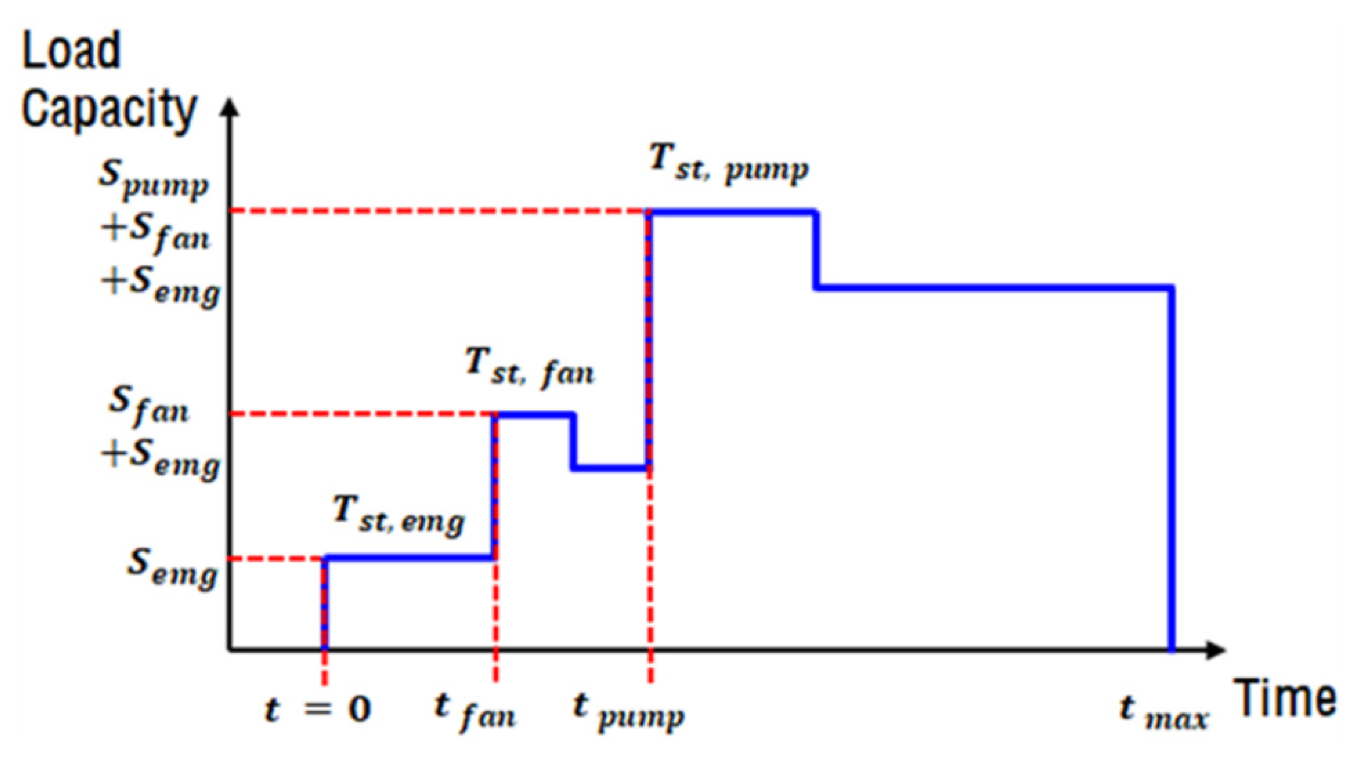
STEP 4: The load operation time () of the ESS load test device is applied in order of the making time () of general facility load, start-up time () and stabilization time () of fire-fighting ventilation fans, and start-up time () and stabilization time () of fire-fighting pumps.
In addition, for each load operation, the capacity of emergency loads to be input is classified into reactive power and active power, considering the starting-up characteristics, and calculated using Equation (9). Moreover, Figure 6 shows load operation patterns of the load test device calculated above in a time chart. Furthermore, the maximum operation time () of emergency load is 20 min for buildings with 29 floors or less, 40 min for 30 to 49 floors, and 60 min for 50 floors or higher, in accordance with the relevant states [17,18].
STEP 5: To conduct a field load test, appropriate PCS and batteries which satisfy the capacity calculated according to the ESS load test device operation pattern in STEP 4 are selected.
STEP 6: The operation time () of the ESS load test device is set as the initial value, and the load test is performed according to the operation patterns of the load operation test calculated in STEP 4.
In addition, if the voltage ( < < 102.5%) and frequency (95% < < 105%) supplied to the ESS load test device from the emergency generator satisfy operation range and the operation time reaches the maximum time set, it is determined to be suitable for operation. Meanwhile, if the voltage and frequency supplied from the emergency generator cannot satisfy operation range or the operation time may not reach the maximum time set, a retest is conducted up to three times to determine conformity or nonconformity and terminate the test. The operation algorithm of the ESS load test device for the field load test of the above emergency generator is demonstrated in a flowchart, as shown in Figure 7.
4. Modeling of a Load Test Device Using ESS Based on PSCAD/EMTDC
In order to present characteristics for the proposed load test method and operation algorithm of the load test device using ESS, this chapter performs a modeling of the emergency power system, which is composed of emergency generator, emergency load, ESS, and so on, based on the PSCAD/EMTDC.
4.1. Operation Characteristics of Field Load Test for an Emergency Generator
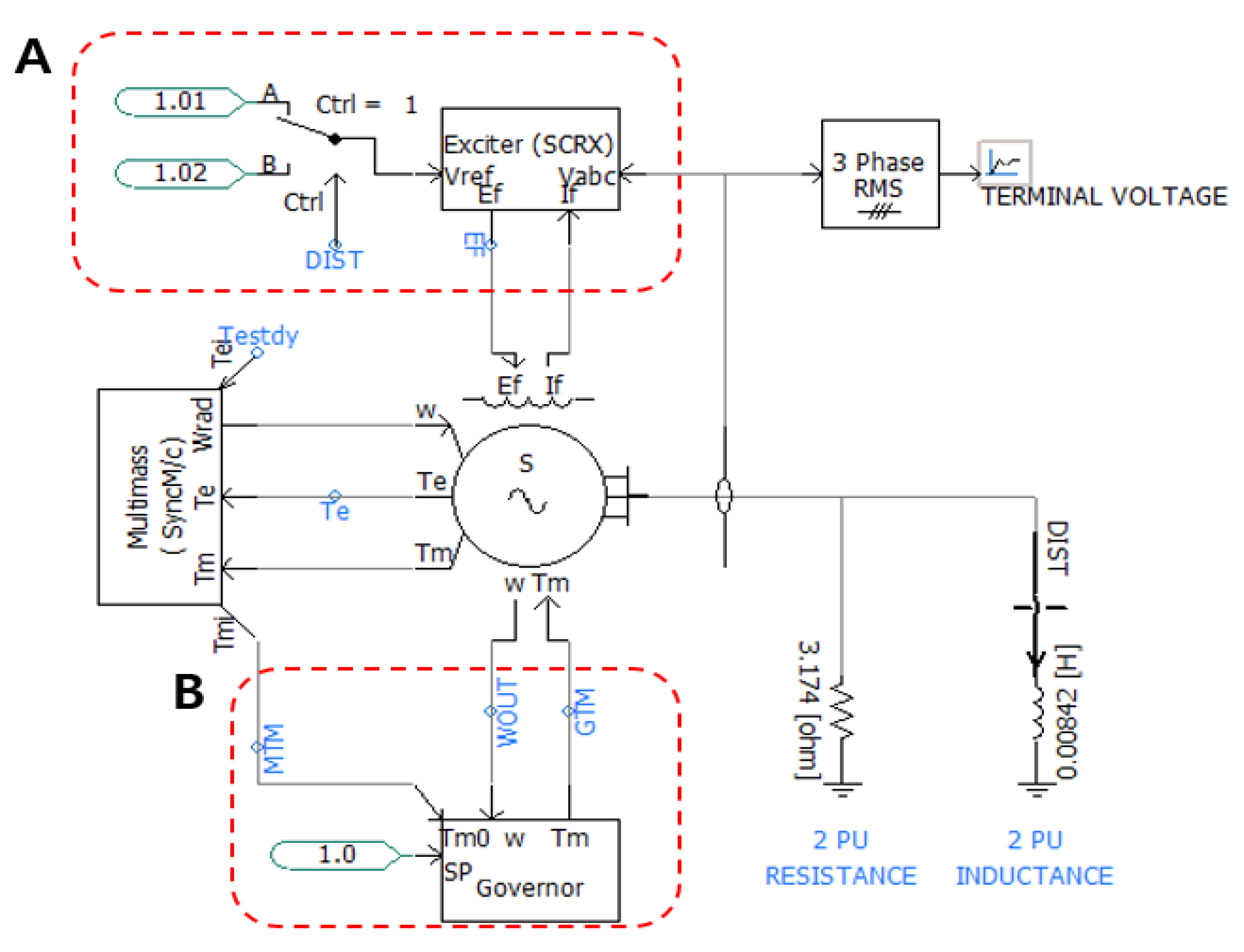
Most of the emergency generators that supply power to emergency load are using a diesel generator. The modeling of a diesel generator, which is composed of an exciter and governor using PSCAD/EMTDC, is shown in Figure 8 [19,20,21,22]. Here, part A of Figure 8 is an exciter that controls the reactive power generated from the diesel generator and controls output voltages using constant voltage regulation. On the other hand, part B of Figure 8 is a governor, which consists of an active power control unit that controls the amount of power required by the emergency power system and a speed regulation unit that maintains the rotation speed of the diesel generator at a constant value.
4.2. Modeling of Emergency Load
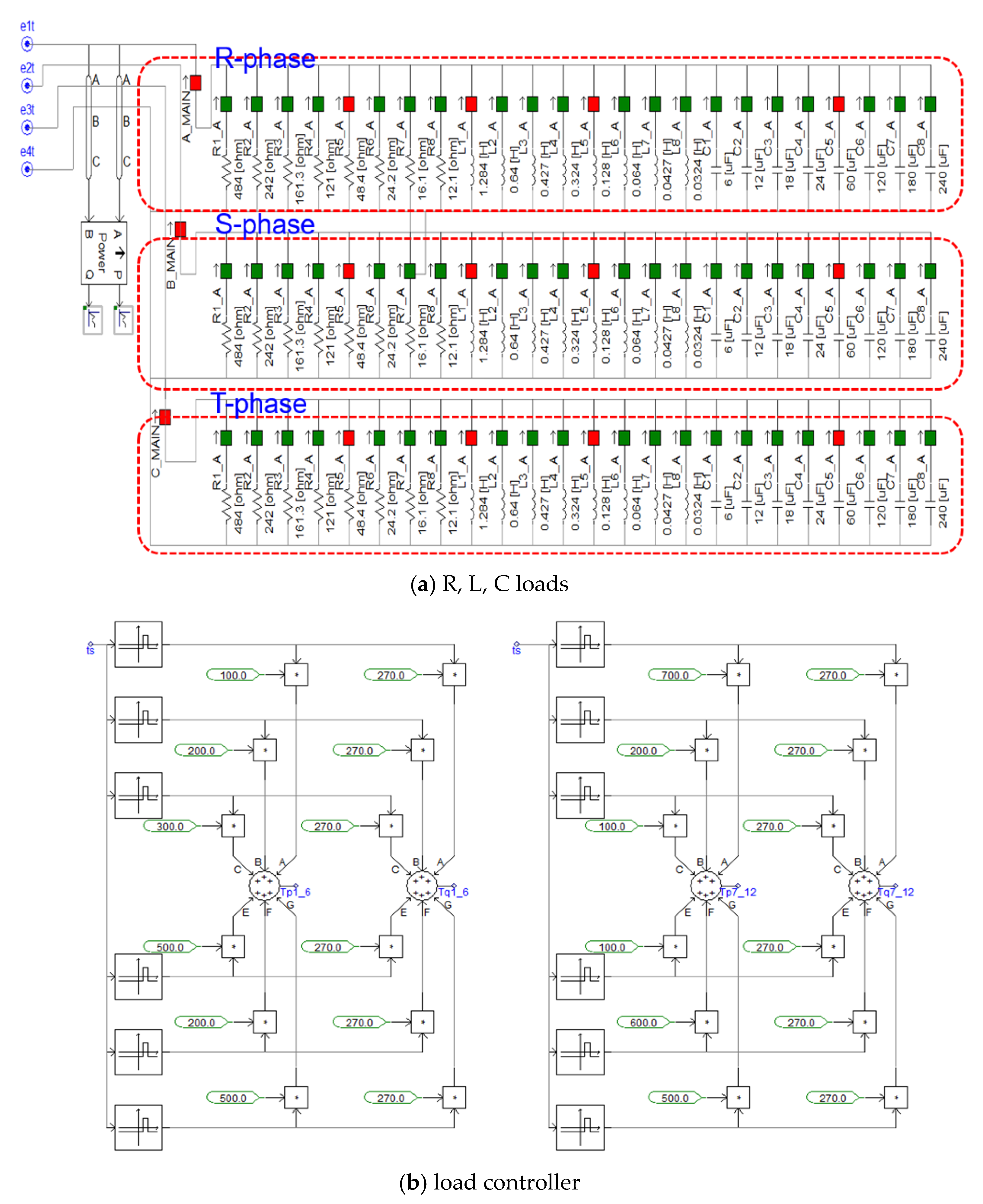
The emergency load consists of fire-fighting facility load to protect humans and property in case of a fire or blackout and general facility load. This emergency load is modeled so that various conditions can be performed by combining R, L, C loads and an induction motor, as shown in Figure 9. Here, Figure 9a shows the resistive load (R) that can be adjusted in the range of 100 W to 10 kW, and the inductive load (L) and capacitive load (C) are adjusted in the range of 100 Var to 10 kVar. In addition, Figure 9b is a load controller, and the load is input according to the operating sequence in the same way as the emergency load characteristics of the emergency power system.
On the one hand, fire-fighting ventilation fans and pumps generally use the induction motors, which have starting-up characteristics where current increases rapidly and power factor decreases during start-up. In addition, it can be represented by Equations (10) and (11). Here, Equation (10) indicates apparent power () of fire-fighting facility load at the start-up, and is calculated by multiplying the apparent power () and starting coefficient (, ). Furthermore, Equation (11) indicates active power () of fire-fighting facility load at the start-up, and is calculated by multiplying the apparent power () at Equation (10) and the average power factor () at start-up.
where, : the apparent power of fire-fighting facility load at start-up (kVA), : power of fire-fighting facility load at apparent power under rated load, : starting kVA (7.2) per 1 kW of fire-fighting motor capacity, : starting coefficient (Y- starting: 0.667, direct on-line starting: 1.0).
where, : the active power of fire-fighting facility load at start-up, : the average power factor (0.4) of fire-fighting facility load at start-up.
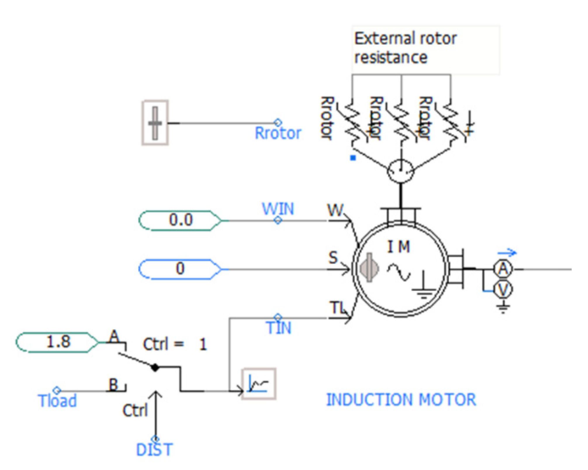
Based on the above Equations (10) and (11) that calculate the capacity of fire-fighting facility load at start-up, the induction motor can be modeled using PSCAD/EMTDC, as shown in Figure 10.
4.3. Modeling of the Load Test Device Using ESS
The ESS load test device for the field load test of the emergency generator must be able to properly control the active and reactive power of ESS by considering starting-up characteristics of emergency load. That is, in order to obtain the target output value of the active and reactive power of ESS, the reference current (,) of the d–q axis determining the output of ESS is calculated, and voltage difference is calculated by comparing the reference link voltage of ESS with the DC link voltage, depending on the target voltage. When the voltage difference is converted into a current by PI control, the reference current of the d–q axis can be calculated using Equations (12) and (13) [23,24,25,26]:
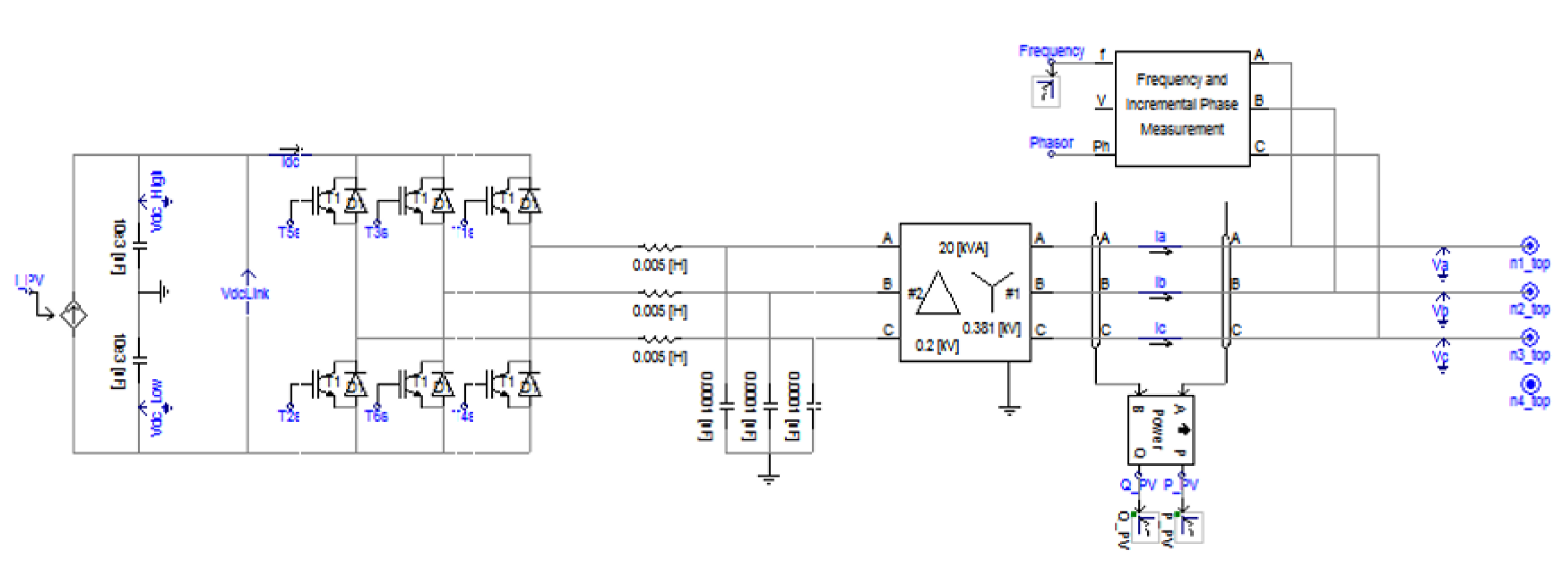
Based on the above interaction Equations (12) and (13) to obtain the reference current of the d–q axis, the ESS load test device capable of charging and discharging with a constant current source is modeled using PSCAD/EMTDC, as shown in Figure 11.
4.4. Entire Modeling of the Emergency Power System
The modeling of an entire emergency power system is composed of an emergency generator, emergency load, and ESS load test device, using PSCAD/EMTDC based on the above, as shown in Figure 12. Here, part A of Figure 12 is the emergency generator, part B is the ESS load test device, part C is the ATS, part D is the emergency load, and part E is the power supply and general load.
5. Case Studies
In order to confirm the usefulness of the proposed method and operation algorithm of the load test device using ESS for an emergency generator, this chapter presents characteristics of the load test for an emergency generator by comparing the load bank and ESS method based on the emergency power system modeling using PSCAD/EMTDC.
5.1. Simulation Conditions
To confirm the usefulness of the field load test method of the emergency generator and the operation algorithm of the ESS load test device presented in this paper, the operational characteristics of the actual power system are compared and analyzed based on the simulation of the emergency power system model. At first, to confirm the operational characteristics of emergency loads that are operated during blackouts and fire accidents, the fire-fighting object completed in 2017 with two basement floors and seven ground floors is selected. The receiving voltage and capacity of the fire-fighting object are 22.9 kV and 700 kVA, the capacity of the emergency load is 400 kW (500 kVA), and the rated capacity of the emergency load is 280.4 kW, as shown in Table 1. Here, the emergency load consists of a fire-fighting facility load of 130.20 kW and general load facility of 150.18 kW. When the demand factor on each facility is applied, the total of fire-fighting facility load and general facility load is 185.18 kW in the event of blackout, and 280.38 kW in the event of fire accidents.
On the one hand, to compare and analyze the operational characteristics of the emergency power system, as shown in Table 2, the loads connected to the emergency generator in case of fire and blackout are classified into induction load (L) and resistance load (R), based on the emergency load calculated above. Referring to the manufacturer’s data sheet, the power factor of emergency load is 0.4 on starting, and 0.8 on rating for L load and 1.0 for R load. Here, the rated capacity of emergency load is 280.4 kW in the event of blackout and 185.2 kW in the event of fire accidents, and the starting capacity of emergency load to be applied for fire is 158.1 kW for extinguishing pump and 21.6 kW for ventilation fan.
In addition, Table 3 shows the operation conditions of emergency loads in order of time, considering the operational characteristics of emergency load of the actual power system in the event of blackout or fire accidents. In the event of a blackout, it is assumed that all L and R loads are operated after 3 s. In the event of fire, L and R loads are assumed to be operated after 3 s, the fire-fighting ventilation fans after 5 s, and the fire-fighting pumps after 10 s.
5.2. Characteristics of the Load Test Device Using ESS
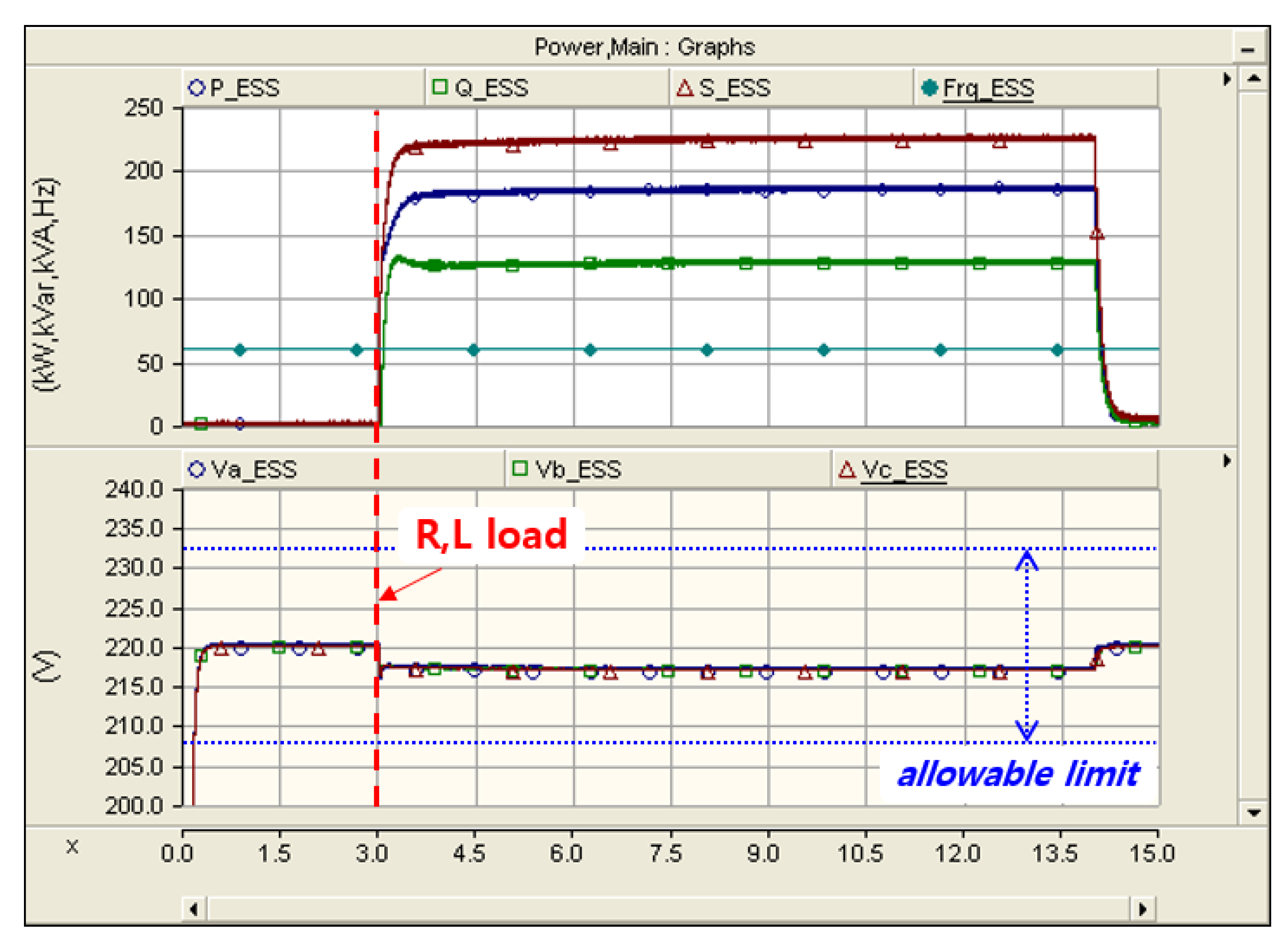
Based on the emergency power system modeled in this paper, Figure 13 and Figure 14 show load characteristics of the emergency generator in the event of a blackout. Here, the output characteristics of the emergency generator by the existing load bank method are shown. The active power and reactive power are calculated as 185.1 kW and 127.4 kVar, as shown in Figure 13. Meanwhile, Figure 14 shows the output characteristics of the active and reactive power of the emergency generator by the charging mode of the ESS load test device presented in this paper. It can be seen that the output of the emergency generator varies due to switching of the PCS, but is almost identical to the output characteristics of the existing load bank.
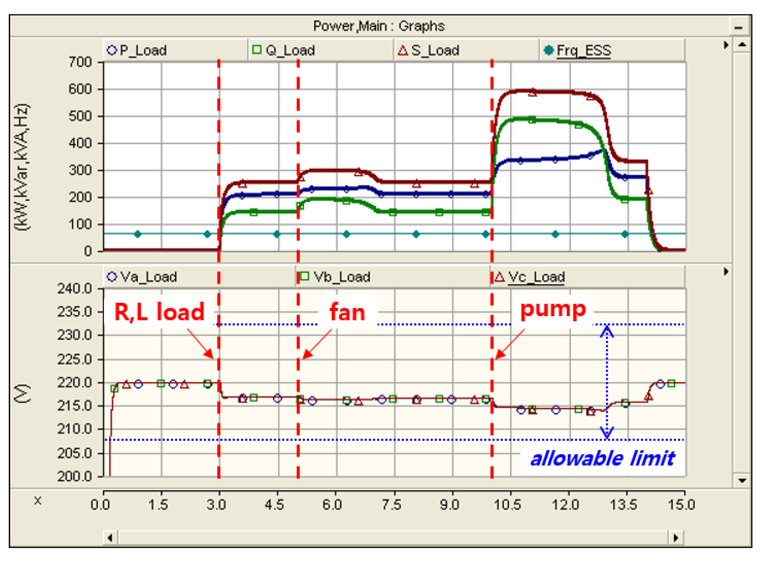
Figure 15 and Figure 16 show the load test characteristics of the emergency generator in the event of a fire. Here, Figure 15 shows the output characteristics of the active and reactive power of the emergency generator by the existing load bank method, and the emergency generator outputs 205.4 kW of active power and 142.8 kVar of reactive power after 3 s, according to the operation pattern of emergency load, and supplies 21.6 kW of active power and 49.5 kVar of reactive power after 5 s due to the starting of the fire-fighting ventilation fan. In addition, the emergency generator is operated by rating to supply 280.2 kW of active power and 199.1 kVar of reactive power to the load bank, after which 150.8 kW of active power and 362.1 kVar of reactive power is output due to the starting of the fire-fighting pumps 10 s later.
On the other hand, Figure 16 indicates the output characteristics of the active and reactive power of the emergency generator by charging mode of the ESS load test device presented in this paper, and it can be seen that it has the same characteristics of emergency generator output by the existing load bank. Therefore, using the ESS load test device proposed, it is validated that the performance of the emergency generator can be checked in the same way as using the emergency load of the actual power system without shutting down the power supply.
5.3. Comparison Results
Table 4 and Table 5 show the output characteristics of emergency load for the existing load bank method and the ESS load test device, using PSCAD/EMTDC modeling. Here, Table 4 shows characteristics in the event of a blackout, and Table 5 shows those in the event of a fire. Then, at load test of the emergency device, it can be confirmed that the result of the simulations for emergency load and ESS load test device are almost identical. Meanwhile, in the characteristics of fire, before and after the start of emergency load (fire-fighting pump), the emergency generator is stably operated with the capacity (400 kW, 500 kVA). However, it can be confirmed that the active power (372.9 kW) is within the capacity range of the emergency generator due to an increase in reactive power (511.7 kVar), which is caused by the rapid current increase followed by power factor drop, but the apparent power (659.8 kVA) exceeds 159.8 kVA, which can cause the emergency generator to shut down. Therefore, if the load test device proposed in this paper is used, the performance of the generator can be checked in the same way as using the actual emergency load without shutting down the power supply, indicating the usefulness of the ESS load test device.
6. Conclusions
There is a situation that an emergency generator is being tested by no-load operation in response to concerns about serious problems, such as damage to the low-voltage equipment due to power supply blackout of the fire-fighting object and the emergency load stopping in the hospitals. To overcome these problems, this paper proposes the field load operation test method of the emergency generator and operation algorithm of the ESS load test device that can check the usage time and output capacity of fire-fighting load by using the ESS of the charging mode consistent with power capacity and characteristics of fire-fighting load as the load device. In addition, to verify the usefulness of the field load test method and the operation algorithm of the ESS load test device proposed in this paper, the emergency power system is performed using PSCAD/EMTDC, and the result is analyzed through simulation. The main contents and expected effects of this paper are summarized as follows:
- (1)
- The simulation results of the emergency power system using PSCAD/EMTDC modeling show that the emergency load test characteristics of the emergency generator are almost identical to the load test characteristics of the ESS load test device. Therefore, the ESS load test device proposed in this paper is useful, because the performance of the generator can be checked in the same way as using the actual emergency load without shutting down the power supply.
- (2)
- When an ESS for load test of the fire-fighting emergency generator consistent with fire-fighting load capacity and characteristics is developed and distributed, it is possible to check and take measures in advance for operation faults and stopping of the emergency generator through the load operation test in the field. Therefore, it can greatly contribute to the improvement of the reliability of fire-fighting emergency power.
- (3)
- When the mobile ESS for load test plan is developed and distributed in the future, it is expected that the ESS should be able to provide complementary win–win business models, such as discharging the power charged to the ESS during emergency generator testing and selling it to an electric power company, or selling or leasing the ESS load test device to industries related to fire-fighting facility inspection.
Author Contributions
All of the authors contributed to publishing this paper. S.-K.C. carried out modeling, simulations, and compiled the manuscript. The literature review and simulation analysis were performed by J.J., who collected the data and investigated early works. All authors have read and agreed to the published version of the manuscript.
Funding
This research was funded by the Konyang University Research Fund in 2020.
Acknowledgments
J.J. and S.-K.C. conceived and designed the method and performed the experiment and revised and edited the manuscript. This research was funded by the Konyang University Research Fund in 2020.
Conflicts of Interest
The authors declare no conflict of interest.
References
- National Fire Agency. Act on Fire Prevention and Installation, Maintenance, and Safety Control of Fire-Fighting Systems; Article 25: In-House Inspection, etc. on Fire-Fighting Systems, etc. Available online: https://elaw.klri.re.kr/eng_mobile/viewer.do?hseq=24385&type=part&key=12 (accessed on 18 August 2021).
- Hasanah, R.N.; Soeprapto, S.; Adi, H.P. Arduino-Based Automatic Transfer Switch for Domestic Emergency Power Generator-Set. In Proceedings of the 2018 2nd IEEE Advanced Information Management, Communicates, Electronic and Automation Control Conference (IMCEC), Xi’an, China, 25–27 May 2018. [Google Scholar]
- Zhou, Y.; Liang, Y.; Li, R. Research on Intelligent Diagnosis Technology of Emergency Diesel Generator in Nuclear Power Plant Based on New Monitoring Method. IOP Conf. Ser. Mater. Sci. Eng. 2019, 677, 032074. [Google Scholar] [CrossRef]
- Muliyati, D.; Bakri, F.; Umami, I.; Sumardani, D.; Ambarwulan, D. The generator operating system automatically uses a motorized change over switch devices. J. Phys. Conf. Ser. 2019, 1402, 044010. [Google Scholar] [CrossRef]
- Korea Electrical Safety Corporation. Inspection Guidelines for Emergency Power Generation Facilities; KESG-IV-M-7-2012; Korea Electrical Safety Corporation: Jeollabuk-do, Korea, 2012. [Google Scholar]
- National Fire Agency. National Fire Safety Code NFSC 102; Article 8: Sources of Electricity; National Fire Agency: Sejong, Korea, 2021.
- The Seoul Institute. A Study on the Utilization of Emergency Generators as a Backup Power System; 2014-PR-11; The Seoul Institute: Seoul, Korea, 2014. [Google Scholar]
- Korea Occupational Safety & Health Agency. Technical Guidelines for Decision and Installation of Emergency Power Source; KOSHA GUIED E-84-2011; Korea Occupational Safety & Health Agency: Seoul, Korea, 2011. [Google Scholar]
- National Fire Protection Association. NFPA 110 Emergency Power Generation; National Fire Protection Association: Quincy, MA, USA, 2001. [Google Scholar]
- Lee, W.K.; Choi, C.S. Analysis on Emergency Power Supplies in Buildings and a Model for Safe Operation of the Emergency Power System. J. Korean Soc. Saf. 2012, 27, 49–56. [Google Scholar]
- Korea Electric Engineers Association. An Investigation on the Operational Status and Perception of Emergency Power Generators for Effective Response to Power Supply Crisis; Korea Electric Engineers Association: Seoul, Korea, 2013. [Google Scholar]
- Ministry of Trade, Industry & Energy. The ESS Will Be a Way to Utilize Emergency Power Source; Press Resources: Berlin, Germany, 2016.
- Lee, E.-C.; Kim, J.-C. Analysis of Starting-up Characteristics for Large-Scaled Induction Motor. J. Korean Inst. Electr. Electron. Mater. Eng. 2013, 26, 30–36. [Google Scholar]
- Choi, S.-K. A Study on Economic Evaluations of ESS Load Test Device for Field Load Test in Fire-fighting Emergency Generator Systems. J. Korea Acad. Ind. Coop. Soc. 2020, 21, 380–386. [Google Scholar]
- Choi, S.K.; Lee, H.D.; Choi, S.S.; Ferreira, M.; Rho, D.S. A Study on the Implementation and Modeling of 20kW Scale ESS Load Test Device for Emergency Generator. J. Korea Acad. Ind. Coop. Soc. 2019, 20, 541–550. [Google Scholar]
- Kim, H.-J. Causes and Countermeasures of Safety Accidents for Energy Storage Systems. J. KSME 2020, 60, 30–33. [Google Scholar]
- National Fire Agency. NFSC-103 Fire Safety Standards for Sprinkler Facilities; National Fire Agency: Sejong, Korea, 2021.
- National Fire Agency. NFSC 604 Fire Safety Standards for Tall Buildings; National Fire Agency: Sejong, Korea, 2017.
- Wang, J.Y.; Kim, B.K.; Park, J.B.; Kim, B.M.; Kim, E.S.; Rho, D.S. A Study on the Modeling and Operation Algorithm of Independent Power System for Carbon Free. Trans. Korean Inst. Electr. Eng. 2016, 65, 760–768. [Google Scholar] [CrossRef]
- Choi, H.Y.; Choi, S.S.; Kang, M.K.; Rho, D.S. Optimal Voltage Control Algorithm of Small Hydro Generators for Voltage Stabilization in Distribution system with large scaled PV systems. Trans. Korean Inst. Electr. Eng. 2018, 67, 824–832. [Google Scholar]
- Friedel, V. Modeling and Simulation of a Hybrid Wind-Diesel Microgrid. Master’s Thesis, The School of Electrical Engineering Royal Institute of Technology, Stockholm, Sweden, 2009. [Google Scholar]
- Palle, B.; Uriarte, C.; Simoes, M.G.; Chakraborty, S. Electrical Model Development and Validation for Distributed Resources; NREL/SR-581-41109; Colorado School of Mines Golden: Golden, CO, USA, 2007. [Google Scholar]
- Kang, M.K.; Choi, S.S.; Park, J.B.; Nam, Y.H.; Kim, E.S.; Rho, D.S. A Study on the Modeling Method of Performance Evaluation System for MW Scaled Energy Storage System Using the PSCAD/EMTDC. Trans. Korean Inst. Electr. Eng. 2017, 66, 885–891. [Google Scholar]
- Nam, Y.H.; Choi, S.S.; Kang, M.K.; Lee, H.D.; Park, J.H.; Rho, D.S. A Study on the Large-scale Adoption Method of Distribution System Interconnected with PV System by Energy Storage System. Trans. Korean Inst. Electr. Eng. 2018, 67, 1031–1039. [Google Scholar]
- Choi, S.S.; Kang, M.K.; Lee, H.D.; Nam, Y.H.; Park, J.H.; Rho, D.S. A Study on an Evaluation Modeling of Power System Performance for Frequency Regulation ESS Based on the PSCAD/EMTDC. Trans. Korean Inst. Electr. Eng. 2018, 67, 1024–1030. [Google Scholar]
- Tazay, A.; Miao, Z.; Fan, L. Blackstart of an Induction Motor in an Autonomous Microgrid. In Proceedings of the 2015 IEEE Power & Energy Society General Meeting, Denver, CO, USA, 26–30 July 2015; pp. 1–5. [Google Scholar]
Figure 1.
Starting-up characteristics of an inductor motor.

Figure 2.
Load test method of an emergency generator with a load bank.

Figure 3.
Load test method of an emergency generator with back-to-back PCS.

Figure 4.
Load test method of an emergency generator with ESS.

Figure 5.
Configuration of the load test device with ESS.

Figure 6.
Operation patterns of the ESS load test device.

Figure 7.
Operation algorithm of the load test device with ESS.

Figure 8.
Modeling of the diesel generator.

Figure 9.
Modeling of the emergency load.

Figure 10.
Modeling of the induction motor.

Figure 11.
Modeling of the ESS load test device.

Figure 12.
Modeling of the entire emergency power system.

Figure 13.
Output characteristics of the generator for the load bank in fault condition.

Figure 14.
Output characteristics of the generator for the ESS load test device in fault condition.

Figure 15.
Output characteristics of the generator for the load bank in fire conditions.

Figure 16.
Output characteristics of the generator for the ESS load test device in fire conditions.


Table 1.
Capacity of the actual emergency power system.
| Emergency Load | Type of Load | Capacity of Load | Demand Factor | Acceptance Load | |
|---|---|---|---|---|---|
| kW | % | ||||
| Fire-fighting load | Pumpingload1 | 65.82 | 100 | 65.82 | |
| Pumpingload2 | 3.70 | 100 | 3.70 | ||
| Fan1 | 9.00 | 100 | 9.00 | ||
| Fan2 | 9.00 | 100 | 9.00 | ||
| Fan3 | 3.84 | 100 | 3.84 | ||
| Fan4 | 3.84 | 100 | 3.84 | ||
| Elevator | 20.00 | 100 | 20.00 | 20.00 | |
| Emergencylamp | 5.00 | 100 | 5.00 | 5.00 | |
| Loadforfirefighting | 10.00 | 100 | 10.00 | 10.00 | |
| Subtotal | 130.20 | 35.00 | 130.2 | ||
| Normal customer load | Pumpingload1 | 11.52 | 100 | 11.52 | 11.52 |
| Pumpingload2 | 9.00 | 100 | 9.00 | 9.00 | |
| Pumpingload3 | 2.70 | 100 | 2.70 | 2.70 | |
| Pumpingload4 | 2.70 | 100 | 2.70 | 2.70 | |
| Pumpingload5 | 5.54 | 100 | 5.54 | 5.54 | |
| Refrigerator | 10.20 | 100 | 10.20 | 10.20 | |
| Heat Exchanger | 11.52 | 100 | 11.52 | 11.52 | |
| Coolingload | 65.00 | 100 | 65.00 | 65.00 | |
| Circulationpumpingload | 32.00 | 100 | 32.00 | 32.00 | |
| Sub-total | 150.18 | 86.97 | 86.97 | ||
| Total | 280.38 | 185.2 | 280.4 | ||
Table 2.
Capacity of the emergency power system by load characteristics.
| Case | Type of Load | Capacity of Rated Load | Capacity of Starting Load | ||||||
|---|---|---|---|---|---|---|---|---|---|
| P.F | kW | kVar | kVA | P.F | kW | kVar | kVA | ||
| Fire | Pumping load | 0.8 | 65.8 | 49.4 | 82.3 | 0.4 | 158.1 | 362.1 | 395.1 |
| Fan load | 0.8 | 9.0 | 6.8 | 11.3 | 0.4 | 21.6 | 49.5 | 54.0 | |
| L | 0.8 | 190.6 | 142.9 | 238.2 | |||||
| R | 1.0 | 15.0 | 0 | 15.0 | |||||
| Total | 280.4 | 199.0 | 346.7 | 179.7 | 411.6 | 449.1 | |||
| Blackout | L | 0.8 | 170.2 | 127.6 | 212.7 | ||||
| R | 1.0 | 15.0 | 0 | 15.0 | |||||
| Total | 185.2 | 127.6 | 227.7 | ||||||
Table 3.
Operation conditions of emergency load.
| Time (s) | 1 | 2 | 3 | 4 | 5 | 6 | 7 | 8 | 9 | 10 | 11 | 12 | 13 | 14 | 15 | |
|---|---|---|---|---|---|---|---|---|---|---|---|---|---|---|---|---|
| Fire | Pumping load | |||||||||||||||
| Fan load | ||||||||||||||||
| L | ||||||||||||||||
| R | ||||||||||||||||
| Blackout | L | |||||||||||||||
| R |
Table 4.
Load test characteristics of the emergency generator in a blackout.
| Type of Load | Capacity of Load | ||
|---|---|---|---|
| kW | kVar | kVA | |
| Emergency load | 185.1 | 127.4 | 227.6 |
| ESS | 185.3 | 127.7 | 227.9 |
Table 5.
Load test characteristics of the emergency generator in a fire.
| Type of Load | Operation State of Pumping Load | Capacity of Load | ||
|---|---|---|---|---|
| kW | kVar | KVA | ||
| Emergency load | Stop | 205.4 | 142.8 | 253.1 |
| Starting-up | 372.5 | 511.6 | 659.7 | |
| Steady-state | 280.2 | 199.1 | 346.5 | |
| ESS | Stop | 205.5 | 142.9 | 253.4 |
| Starting-up | 372.8 | 511.7 | 659.8 | |
| Steady-state | 280.5 | 199.3 | 347.9 | |
Publisher’s Note: MDPI stays neutral with regard to jurisdictional claims in published maps and institutional affiliations. |
© 2021 by the authors. Licensee MDPI, Basel, Switzerland. This article is an open access article distributed under the terms and conditions of the Creative Commons Attribution (CC BY) license (https://creativecommons.org/licenses/by/4.0/).
Share and Cite
MDPI and ACS Style
Jin, J.; Choi, S.-K. Operation Method of a Load Test Device Using an Energy Storage System for Site Acceptance Test of a Fire-Fighting Emergency Generator. Energies 2021, 14, 5395. https://0-doi-org.brum.beds.ac.uk/10.3390/en14175395
AMA Style
Jin J, Choi S-K. Operation Method of a Load Test Device Using an Energy Storage System for Site Acceptance Test of a Fire-Fighting Emergency Generator. Energies. 2021; 14(17):5395. https://0-doi-org.brum.beds.ac.uk/10.3390/en14175395
Chicago/Turabian StyleJin, Juan, and Seung-Kyou Choi. 2021. "Operation Method of a Load Test Device Using an Energy Storage System for Site Acceptance Test of a Fire-Fighting Emergency Generator" Energies 14, no. 17: 5395. https://0-doi-org.brum.beds.ac.uk/10.3390/en14175395
Note that from the first issue of 2016, this journal uses article numbers instead of page numbers. See further details here.