
Thermal Management Systems and Waste Heat Recycling by Thermoelectric Generators—An Overview


1
School of Mechanical Engineering, University of Adelaide, Adelaide 5005, Australia
2
Centre for Energy Technology, School of Mechanical Engineering, University of Adelaide, Adelaide 5005, Australia
3
Department of Electrical and Computer Engineering, North Carolina State University, Raleigh, NC 27606, USA
4
Department of Materials Science and Engineering, North Carolina State University, Raleigh, NC 27606, USA
5
ARC Research Hub for Graphene Enabled Industry Transformation, University of Adelaide, Adelaide 5005, Australia
6
Institute for Photonics and Advanced Sensing, University of Adelaide, Adelaide 5005, Australia
*
Author to whom correspondence should be addressed.
Energies 2021, 14(18), 5646; https://0-doi-org.brum.beds.ac.uk/10.3390/en14185646
Submission received: 2 August 2021
/
Revised: 30 August 2021
/
Accepted: 1 September 2021
/
Published: 8 September 2021
(This article belongs to the Topic Thermoelectric Energy Harvesting)
Abstract
:With the fast evolution in greenhouse gas (GHG) emissions (e.g., ,) caused by fossil fuel combustion and global warming, climate change has been identified as a critical threat to the sustainable development of human society, public health, and the environment. To reduce GHG emissions, besides minimizing waste heat production at the source, an integrated approach should be adopted for waste heat management, namely, waste heat collection and recycling. One solution to enable waste heat capture and conversion into useful energy forms (e.g., electricity) is employing solid-state energy converters, such as thermoelectric generators (TEGs). The simplicity of thermoelectric generators enables them to be applied in various industries, specifically those that generate heat as the primary waste product at a temperature of several hundred degrees. Nevertheless, thermoelectric generators can be used over a broad range of temperatures for various applications; for example, at low temperatures for human body heat harvesting, at mid-temperature for automobile exhaust recovery systems, and at high temperatures for cement industries, concentrated solar heat exchangers, or NASA exploration rovers. We present the trends in the development of thermoelectric devices used for thermal management and waste heat recovery. In addition, a brief account is presented on the scientific development of TE materials with the various approaches implemented to improve the conversion efficiency of thermoelectric compounds through manipulation of Figure of Merit, a unitless factor indicative of TE conversion efficiency. Finally, as a case study, work on waste heat recovery from rotary cement kiln reactors is evaluated and discussed.
1. Introduction
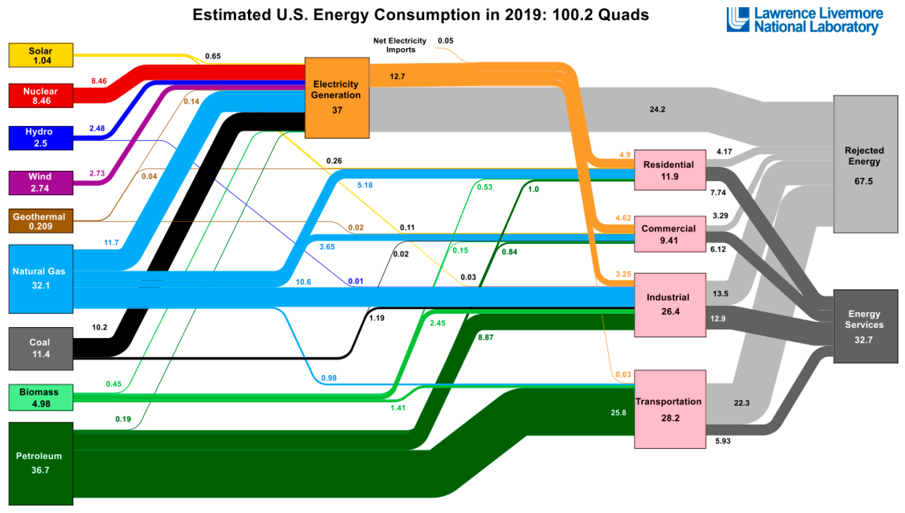
Global warming and the resulting climate change can be traced back to human activities, industrial processes, and the resultant greenhouse gases (GHGs) emissions [1,2]. The primary source of GHGs emissions is the application of fossil fuels for energy production. Therefore, one of the ways to reduce the emission of GHGs is to consume less fossil fuel. However, this is only feasible if the energy is generated and used efficiently, i.e., having the minimum energy loss and recycling the energy loss, which usually comes as waste heat. According to a recent study conducted by the Lawrence Livermore National Laboratory [3], more than 68% of the generated energy is lost as waste heat, Figure 1. However, amongst the energy generation sectors, the majority of the rejected energy (waste heat) in the United States belongs to electricity generation (24.2%), in comparison with the other sectors, including transportation (22.3%), industrial (13.5%), residential (4.17%), and commercial (3.29%), as illustrated in Figure 1.
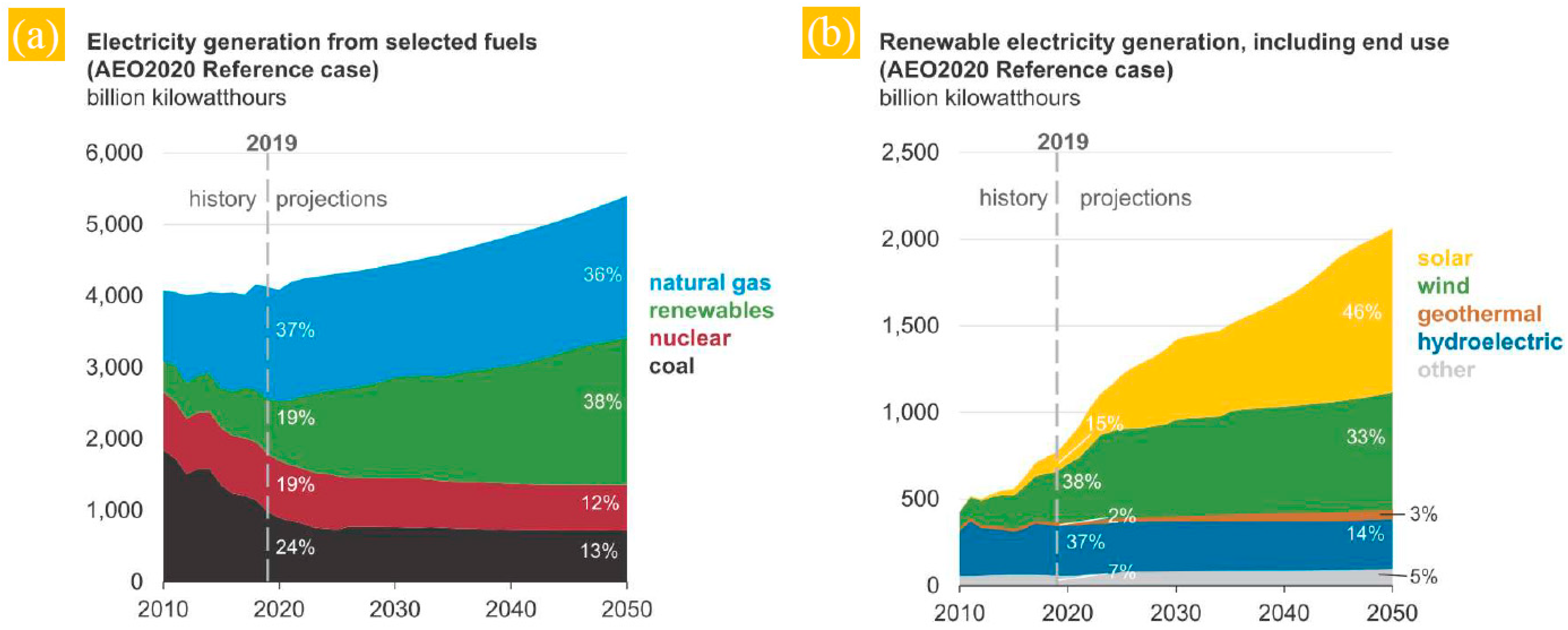
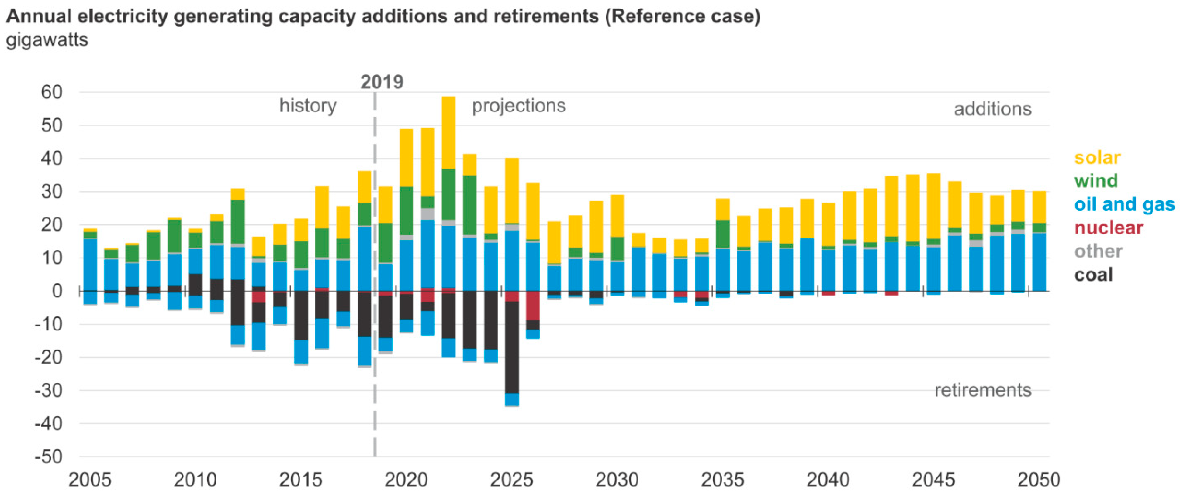
It may take many years until renewable energies reach a position where they can fully replace fossil fuels. Consequently, other intermediate technologies are required to reduce carbon output (e.g., ) and increase the efficiency of the existing energy-generating technologies during this transition period. In this regard, Figure 2 illustrates the electricity generation from fuel energies (Figure 2a) and renewable energy sources (Figure 2b) in the US, which are projected up to 2050. It is anticipated that a greater role for renewable energy sources will satisfy future energy demand, as clearly demonstrated in Figure 3.
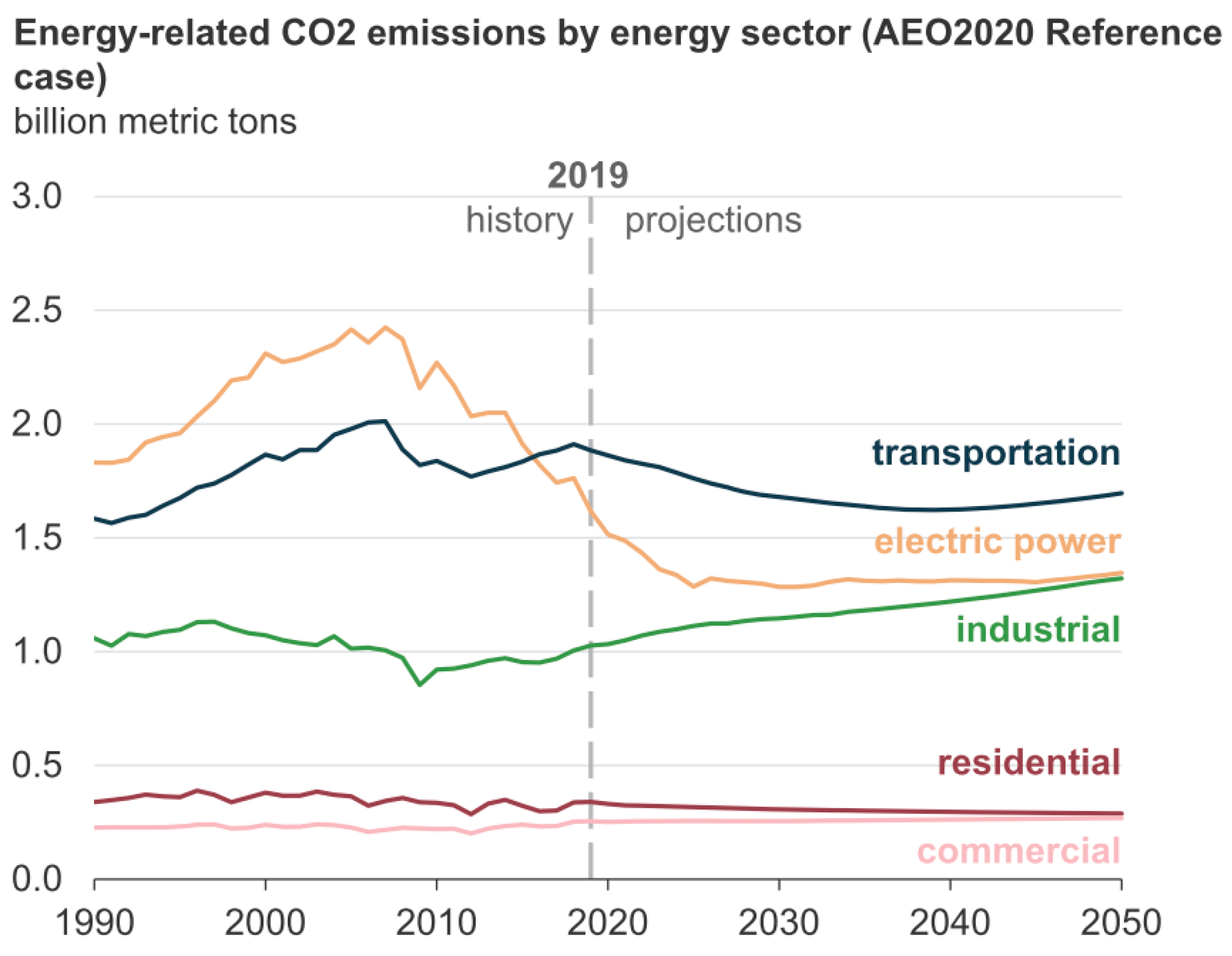
The forecast in Figure 3 is based on the trend of rapid deployment of clean energy technologies, which is encouraging. Such growth in the renewable energy industry is expected to show its impact on the projected emission in the electric power sector, as exhibited in Figure 4. As shown in this figure, the average emissions decrease with time.
The reduction in CO2 emission is related to energy harvesting from the environment by reliable sources, which has now manifested as a worldwide concern. Currently, the relatively low-performance efficiency of the fuel-based engines, industrial and power generation processes leads to a significant fraction of the energy of the fuels being lost as heat. For example, the thermal efficiency of the state-of-the-art petrol engines is ~20%, gasoline engines are ~40%, cement kilns are ~50%, and Rankine cycles for power generation are some 35% [4,5]. Therefore, if the loss of valuable energy to waste heat is reduced through more efficient processes, or the waste heat is converted into more useful energy such as electricity, the environmental impact of energy production will be mitigated.
One solution to capturing waste heat and converting it into electricity is utilizing solid-state energy converters, such as thermoelectric generators (TEGs). In line with this encouraging trend, the application of thermoelectric generators is considered as the potential primary candidate to capture waste heat, for example, in automobile exhaust recovery systems [5,6,7], or harvesting the heating energy dissipating from current renewable energy sources (e.g., concentrated solar heat exchangers) [8]. Therefore, the central theme of this paper is to discuss the advances in thermoelectricity and its applications in energy recovery to highlight the benefits of thermoelectric generators in converting waste heat to electricity without any taxing on the environment.
2. History of Thermoelectricity
The concept of thermoelectricity (TE) as the direct conversion of temperature gradient () into electricity was instigated by the German-Estonian physicist Thomas Johann Seebeck in the years between 1821 and 1831 [9,10]. The Seebeck coefficient (, V/K) was estimated based on the generated voltage () against an imposed temperature difference () [6]—Equation (1),
Further contributions in this field are due to Gustav Magnus, who declared the Seebeck voltage is not dependent on the temperature distribution along the intermediate metals connecting the p-n junctions [11]. Later on, the Peltier effect was introduced to show that the heating or cooling is generated by passing an electric current through two dissimilar materials [9,10]. Furthermore, William Thomson defined the relationship between the Seebeck and Peltier effects [10], and then Edmund Altenkirch calculated the maximum efficiency of the thermoelectric generators [9]. The modern theory of thermoelectricity in materials, however, is due to Abram Fedorovich Ioffe [9], who introduced a dimensionless factor named “figure of merit ()”. It is a metric for evaluating the thermoelectric behavior (performance) of thermoelectric compounds (materials);
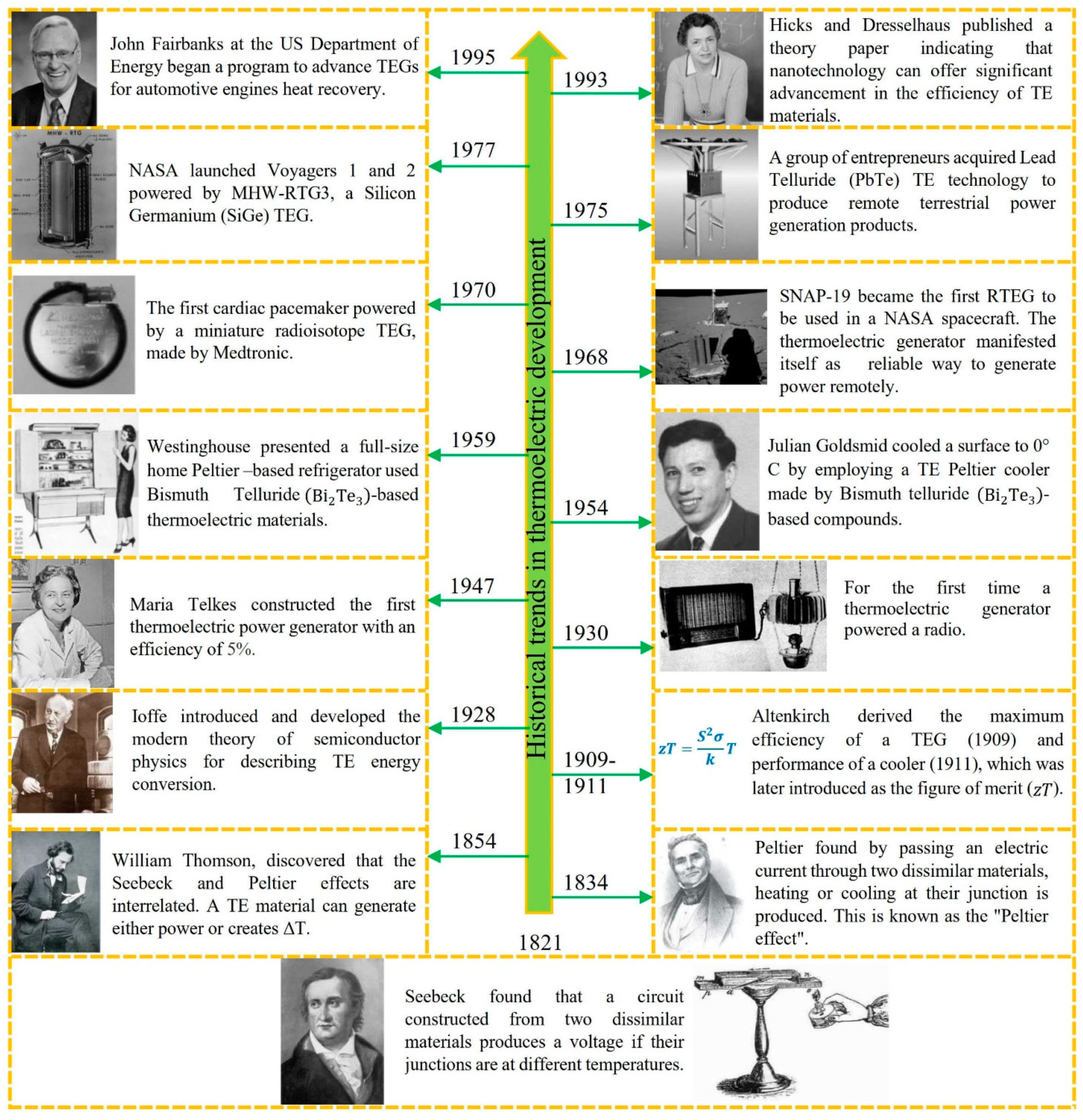
where is the Seebeck coefficient (μVK−1), is the electrical conductivity (Ω−1m−1), is the temperature (K), and and are electronic and lattice thermal conductivities (Wm−1K−1), respectively [12]. The following chart (Figure 5) summarizes the historical trend in thermoelectric development.
Following the introduction of the fundamentals on thermoelectricity during the 19th and 20th centuries, the 21st century is witnessing the application of the TE fundamentals in developing advanced technology through the fabrication of thermoelectric generators and their subsequent use in introducing intelligent devices with immense effects on the well-being of our society.
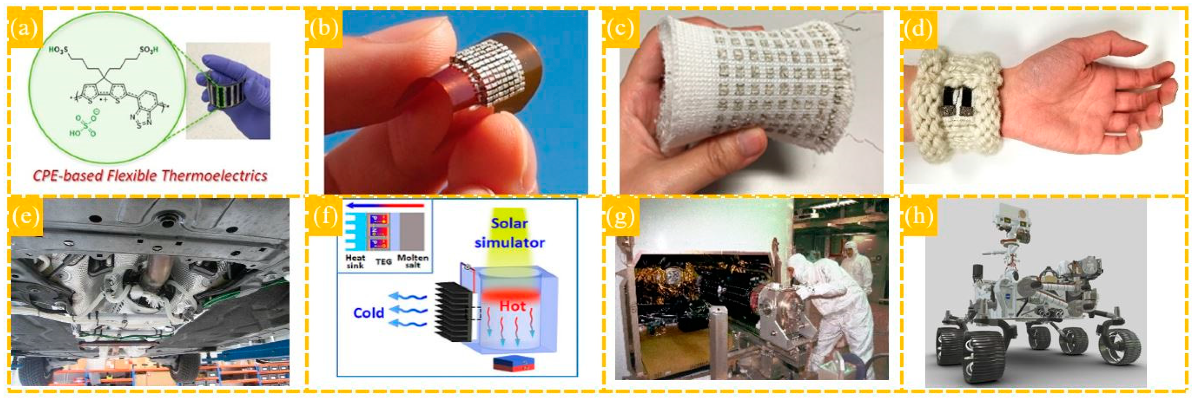
Figure 6 provides some examples of the recent applications of thermoelectric generators. According to this figure [16,17,18,19,20,21,22,23,24], the exploration of new TE materials has extended the application of the TEGs from low-temperature range, such as room temperature for capturing human body heat [18,20], to medium temperature for recovering car exhaust heat [21], and then they have been functionalized at high temperatures for NASA emissions to empower discovery rovers [23,24].
3. Thermoelectric Materials and Designs
The efficiency of thermoelectric generators is very much dependent on the conversion efficiency of the constituent thermoelectric (TE) compounds [25,26,27,28,29]. Therefore, the introduction of advanced thermoelectric materials is crucial in increasing the waste heat-electricity conversion rate. Today, the central theme of research in different laboratories worldwide is to explore and improve thermoelectric materials.
The importance of as the main material-dependent factor is evident when the maximum efficiency () of the thermoelectric (TE) generators (p and n junction) is calculated as;
where and are the temperatures of the hot and cold surfaces, respectively, and is the figure of merit at the average temperature () of the hot and cold junctions [30]. As evident in Equation (3), a large thermal gradient ( − ) can increase the TE efficiency. However, a large thermal gradient may also impose thermal stresses that may compromise the mechanical integrity of the TE compounds. Therefore, in addition to the appropriate thermoelectric characteristics, the TE materials should have thermal and mechanical stabilities to function under harsh conditions.
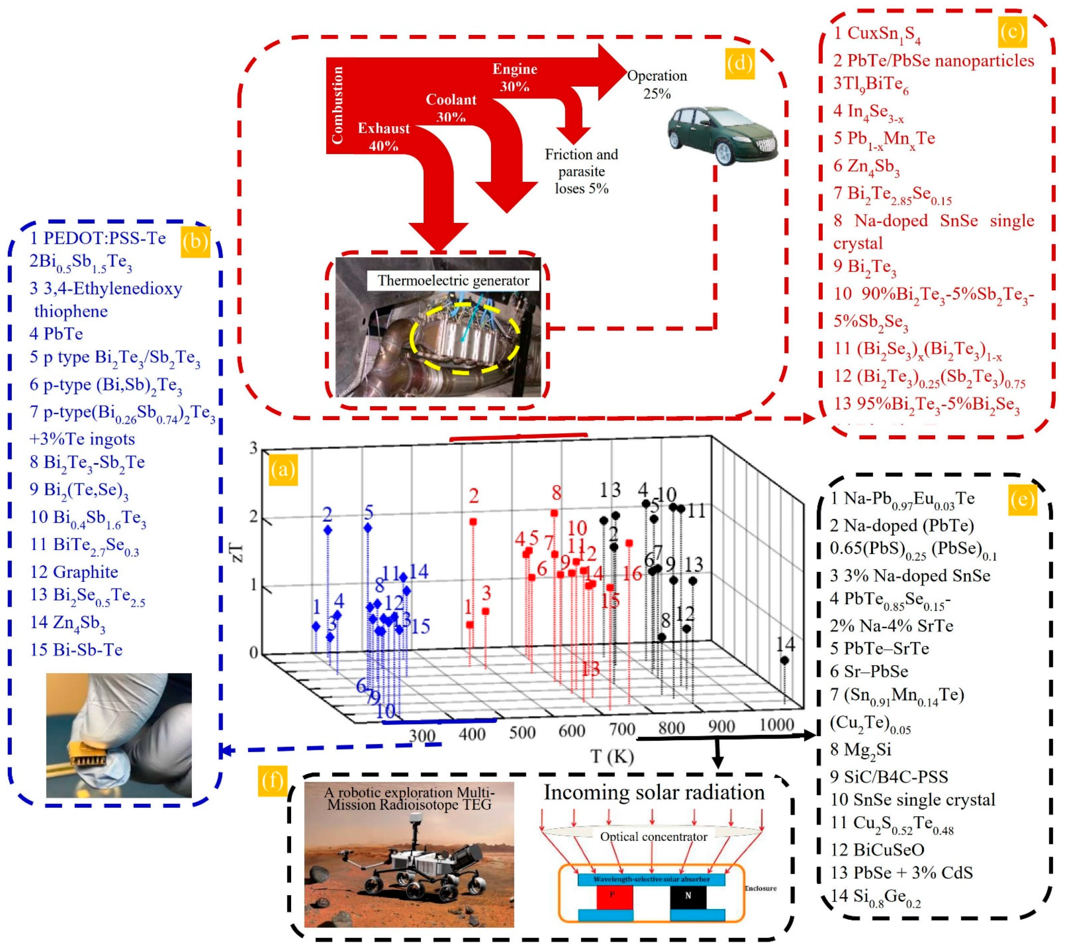
There is a range of thermoelectric materials classified as clathrates [31,32,33], skutterudites [34,35,36,37], chalcogenides [38,39,40], and half-Heuslers [41,42,43,44,45,46,47,48]. However, most studies are concentrated on microstructural manipulation to improve the thermoelectric parameters () at various temperatures. In this regard, the stoichiometry of the p and n-type TE compounds is the critical variable. For example, Figure 7 shows values for thermoelectric products at different temperatures. As illustrated in this figure, different TE compounds with various values confirm their dependency on the constituent elements.
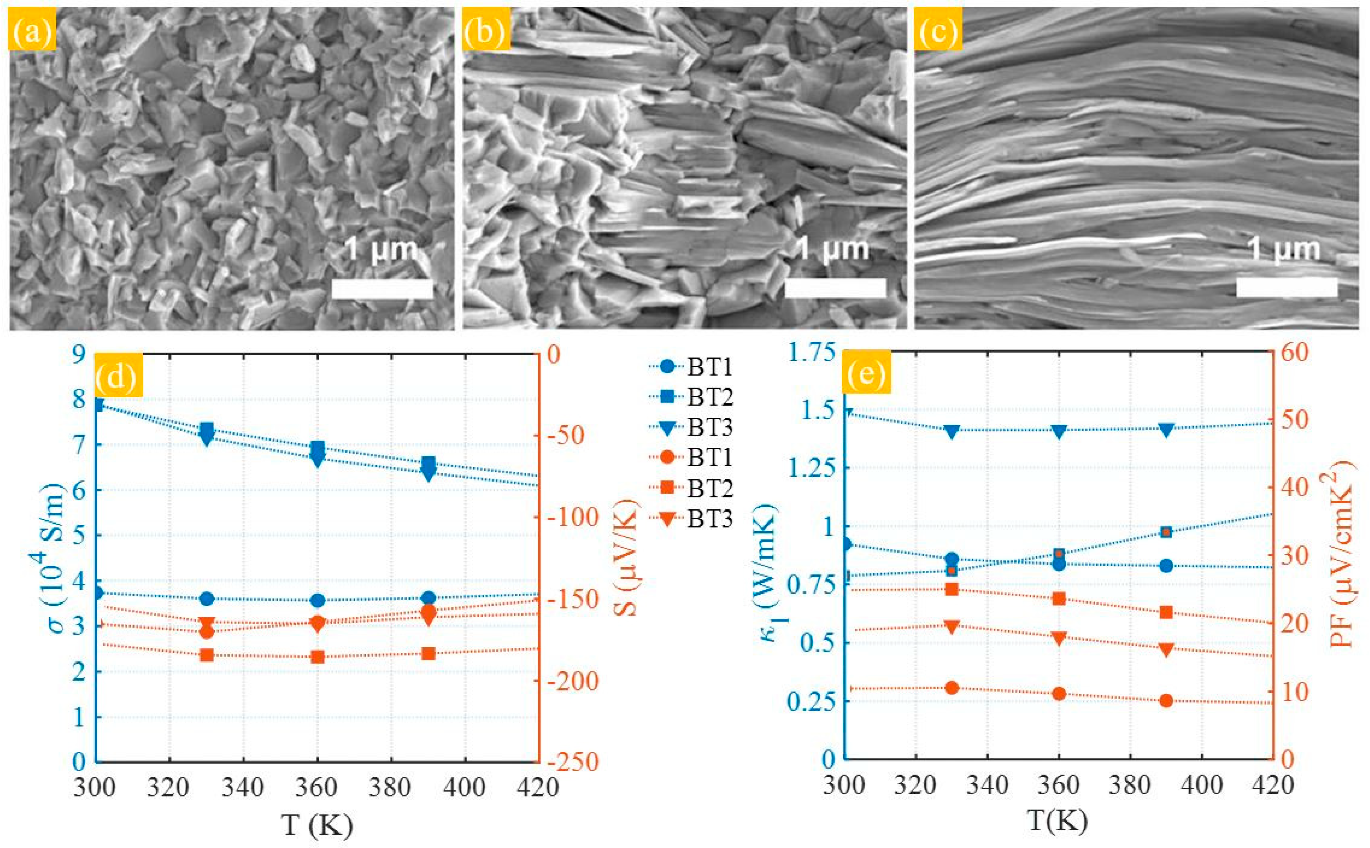
The search for advanced TE materials reveals the necessity of designing products containing nontoxic/eco-friendly elements, sustainable at harsh conditions and high temperatures. Based on the dimensionless figure of merit (Equation (2)), there should be a correlation between the thermoelectric parameters to make an efficient TE product with reasonable . Therefore, the effective factors, including the Seebeck (), and electrical (), and thermal () conductivities, must be optimized, considering the thermal stability of the materials. The TE factors of and are mainly related to the electronic band structure parameters, usually calculated from the first principles. However, thermal conductivities can be modified via microstructural manipulation to increase the heat carriers scattering and reduce thermal conductivities. Significant efforts by the TE community over the last few decades have been concentrated on various techniques to improve thermoelectric properties, based on modifying , , and [53,54,55,56,57], such as nanostructuring [58,59,60,61]. For instance, Figure 8 illustrates the impact of microstructure through changes in particle morphology on the thermoelectric properties, including electrical conductivity, Seebeck coefficients, lattice thermal conductivity, and power factor. The reported impact of the microstructure on thermoelectric factors was discussed based on the modification in carrier concentration, carrier mobility, and effective mass [62]. The readers are referred to this work [62] for more information since the further discussion is outside the scope of the current paper.
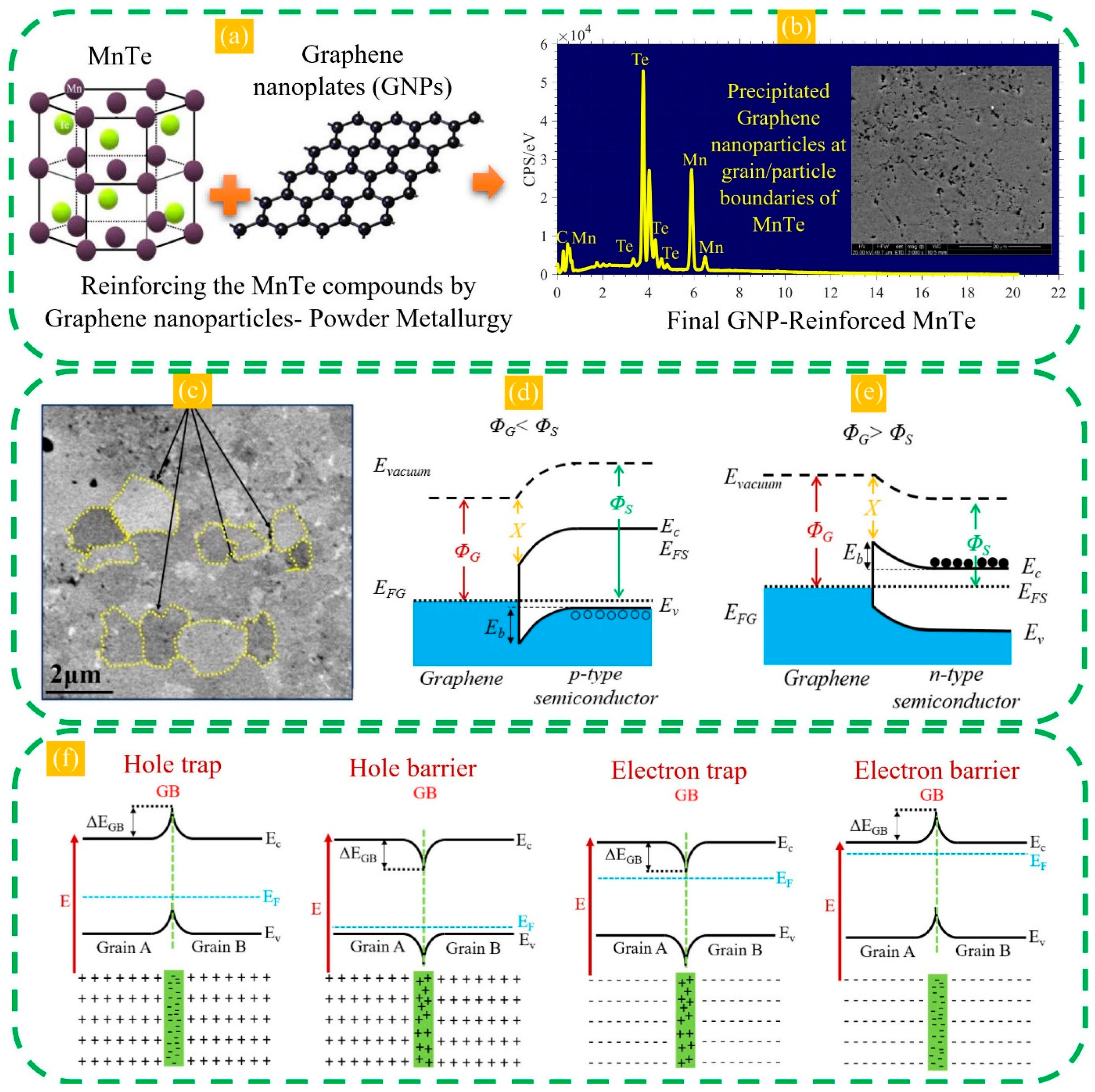
Another approach for manipulation of microstructure through reinforcing nanoparticles such as graphene nanoplates (GNPs) has been investigated in previous works of this group [28,63] for two thermoelectric nanocomposites, namely MnTe-GNPs and CoVSn-GNPs (Figure 9). The results revealed an improved modification in the thermoelectric parameters, mainly in the Seebeck coefficients (27% increase) and thermal conductivity (34% decrease) for the samples reinforced with 0.25 wt.% GNPs in comparison to the pristine MnTe samples at the temperature of 600 K. Moreover, dispersion and precipitation of GNPs in the CoVSn multiphase microstructure influenced the thermoelectric factors by reducing the thermal conductivity and increasing the Seebeck coefficient, leading to the enhancement of the thermoelectric figure of merit. The change in the thermoelectric factor was attributed to the phonon scattering at the grain boundaries beside carrier filtering against the band bending (Schottky barriers) (see Figure 9d–f).
Many more strategies have been studied to enhance the performance of thermoelectric compounds. The examples would be materials selection (as described in Figure 7) [64,65,66], sintering method (e.g., pondermotive force in microwave sintering enhances the diffusion of mobile ionic species and results in accelerating the solid-state reaction by increasing the collision probability) [67], band engineering (e.g., modulation doping, resonance level, and band convergence) [68,69,70,71,72,73,74], carrier pocket engineering [75,76,77], complex structures [78,79], carrier energy filtering [80,81], creation of resonant energy levels close to the band edges [70], low dimensional structures [82,83], magnetic interaction (e.g., carrier trapping and magnon (spin wave) excitations) [84,85], and lowering the thermal conductivity (e.g., phonon scattering) [58,86,87,88,89,90].
4. Waste Heat Sources
Over the past few years, assessing the primary energy-user sectors reveals that a large amount of thermal energy is wasted (Figure 10).
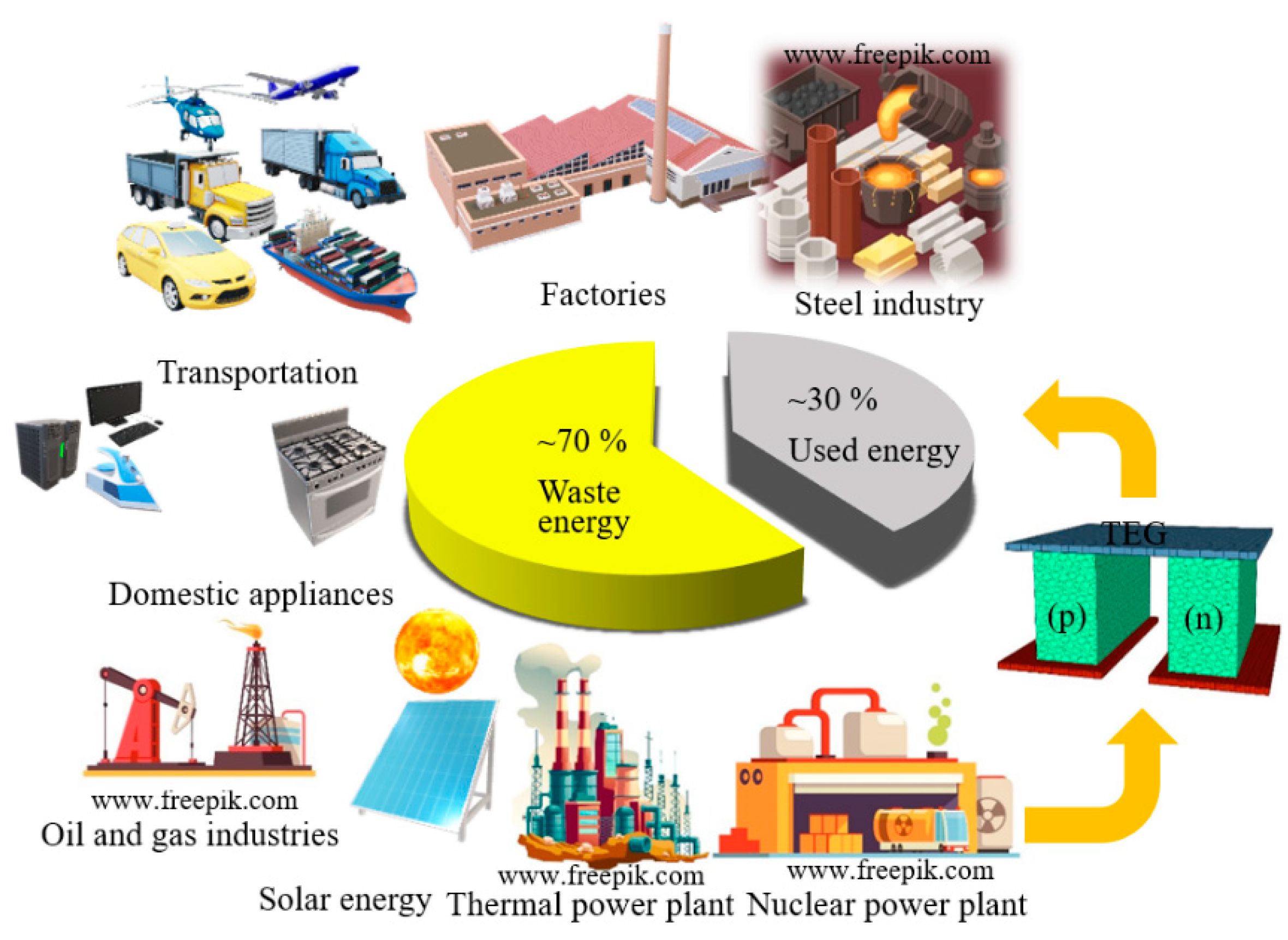
According to the estimation [18], several segments have contributed to wasting thermal energies, from industrial to domestic applications, as described in Figure 10, which can be potentially equipped with thermoelectric generators for converting (recycling) the waste heat into electricity. As a case study and to further justify the rationale and economic benefits behind TEG application in the industrial sectors, the preliminary studies on waste heat recycling from rotary kiln surfaces are discussed and analyzed in the subsequent sections.
5. Case Study: Waste Heat Recycling from Cement Rotary Kilns
Cement subsectors are considered among the most energy-intensive industries, which absorb about 12–15% of the total energy consumed by the industry [91]. This industry is perhaps one of the most polluting industrial sectors, producing about 7% of the man-made carbon dioxide emissions each year [92]. In theory, approximately 1674–1799 kJ energy with no heat loss is required to produce one kilogram of cement clinker [93]. However, in practice, the required energy to manufacture one kilogram of cement clinker is reported in the range of 2750–4500 kJ [93]. Also, to produce one tonne of cement, average electrical energy of 110–120 kWh is required [93]. The cement rotary kiln is the heart of the manufacturing stage for large-scale industrial cement production. In this process, basic raw materials are continuously heated along the kiln length for dehydration, preheating, and calcination with a significant amount of parasitic heat lost through the rotary kiln shell, which is needed to lower the temperature of the shell relative to that of the reactor inside, which can result in temperature to ~1450 °C over the clinkering part of the reactor. The heat loss from the outside surface of the shell enables keeping the operating temperature of the shell structure within a reasonable range and, hence, increasing the lifetime of the shell. This also implies the significance of developing appropriate heat recovery systems from the shell, enabling the conversion of the lost heat into energy without changing operating conditions. Commensurate with this, the calculations in a case study [94] showed that the mean daily heat loss via the calcination zone of a kiln shell with a production capacity of 2500 tons/day is about 140 GJ, attributing to radiation and convection with fractions of ~54% and ~46%, respectively. The industrial cement sectors have been considering recycling waste heat to achieve higher rates of energy conservation and, thus, financial and environmental advantages [91,95,96,97]. Nevertheless, as mentioned above, any employed strategies for heat recovery need to avoid/minimize changes in the temperature distribution within the kiln shell. As discussed above, TEGs can be potentially used for waste heat recovery from the rotary kilns and turn the heat directly into electrical energy [96,97], given that the TEGs and their arrangement around the kiln shell can be purpose-designed to minimize the change in the temperature distribution in the shell, while maximizing their output.
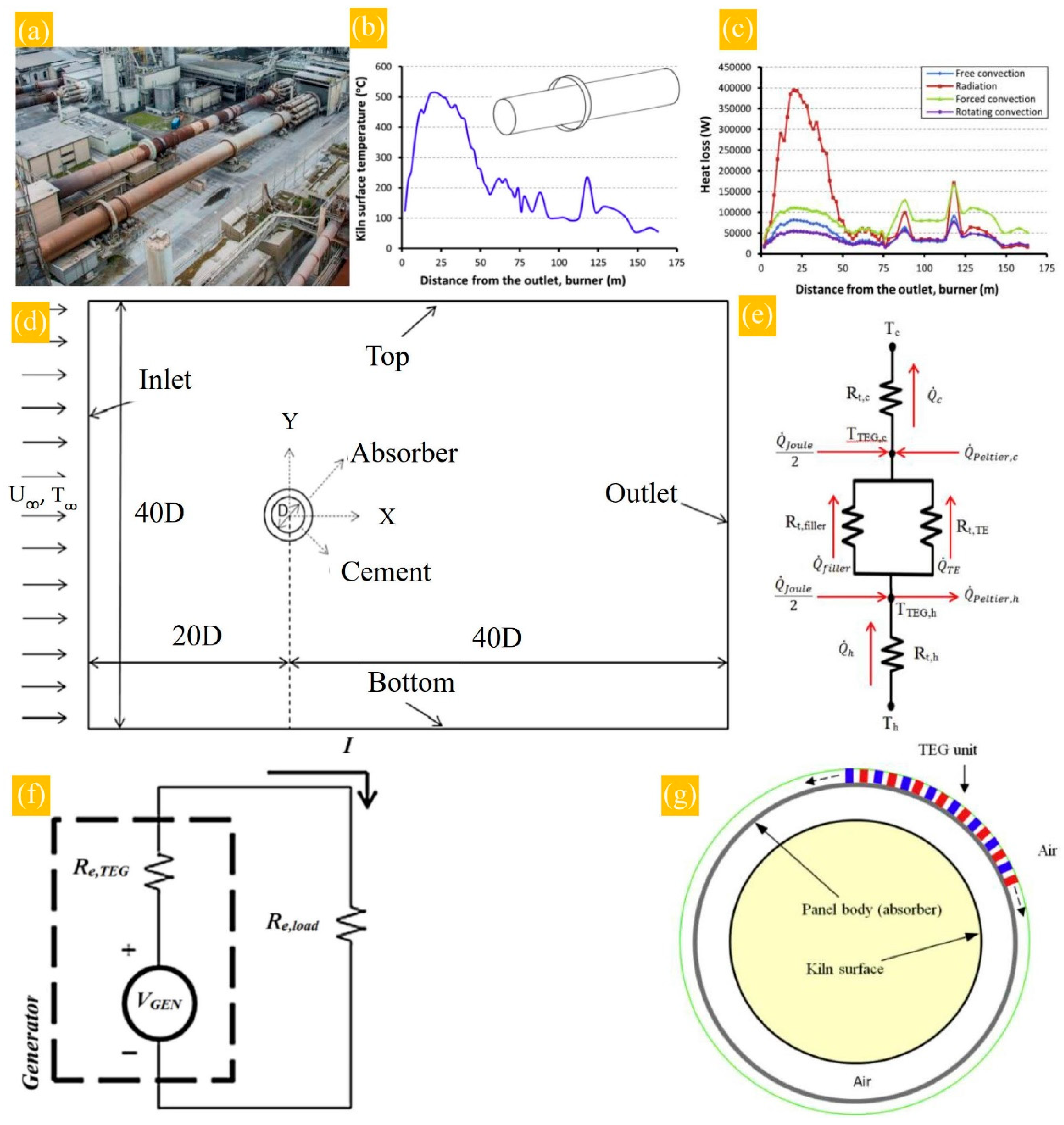
A recent study by Mirhosseini et al. [95] assessed the application of TEG for heat recycling in an Aalborg Portland rotary cement kiln. This investigation proposed applying a local thermal annular absorber integrated with a thermoelectric system to optimize waste heat recovery from the kiln. The absorber collects the heat from the kiln surface, transferred via convection and radiation. Figure 11a shows a view of a cement rotary kiln in the Aalborg Portland cement factory. A numerical simulation was undertaken to evaluate heat loss from the rotary cement kiln. For this purpose, the body temperature of the absorber was determined to report the temperature distribution (Figure 11b). Through the calculations, the surface temperature and free stream air temperature were set to 500 °C and 5 °C, respectively, for the cement kiln shown schematically in Figure 11b (inset). The cement kiln diameter was set at 3.6 m, and the inner diameter of the absorber, made of an aluminum alloy sheet, was considered 4 m. Three heat transfer mechanisms, including free convection, forced convection due to kiln rotation, and radiation, were applied to calculate the heat loss from the external surface of the kiln, as shown in Figure 11c. The simulation calculation domain was carried out with a two-dimensional (2D) unsteady solution, as illustrated in Figure 11d. In this simulation, the one-dimensional thermal equivalent electrical circuit shown in Figure 11e and the electrical resistance networks presented in Figure 11f were considered to calculate the electrical power output for the thermoelectric unit installed on the absorber, see Figure 11g.
The optimization of the simulated TEG was undertaken via a mathematical model based on the finite element method (FEM). To design a thermoelectric recovery generator, two different thermoelectric materials, including bismuth telluride (Bi2Te3) and β-phase zinc antimonide (Zn4Sb3), were used to calculate the electrical power output and TEG performance by considering the financial aspects (e.g., investment cost and production benefits).
Table 1 presents the results of this work [95] according to various parameters, such as the TEG fill factor, leg length of thermocouples, TEG matched power output, total investment cost, cost per power ratio, and payback period. Based on the project outcome, if the cement kiln operates continuously for a year (8760 h), considering the electricity price for household consumption in Denmark ($0.35/kWh), the optimized TEG system fabricated by Bi2Te3- based thermoelectric materials should take about 8.3 years to repay the investment cost. However, the optimized TEG made by Zn4Sb3- based thermoelectric compounds will pay back the investment cost in about 3.5 years. Subsequently, the recovery systems are profitable after these periods.
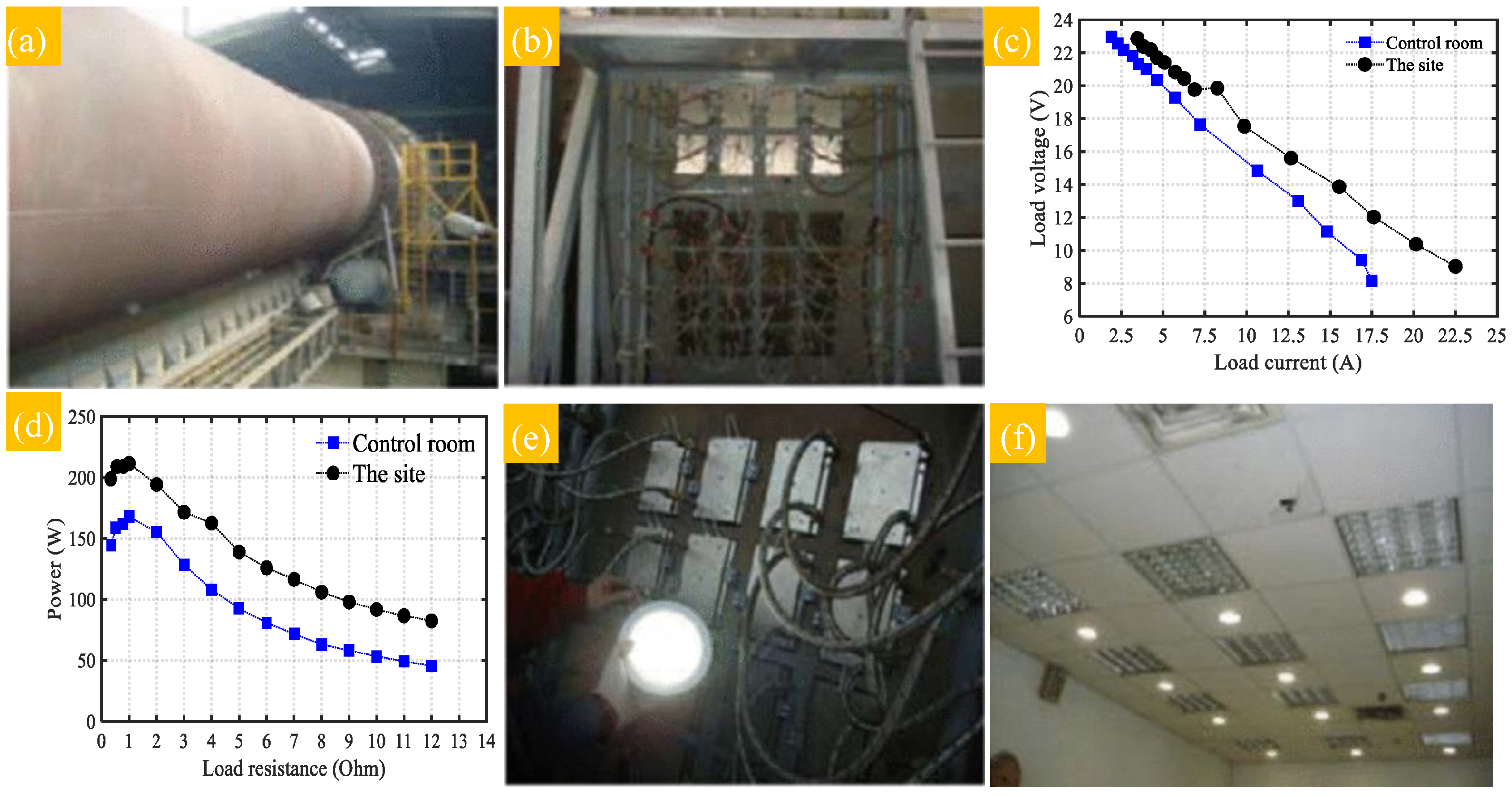
In another study [98], a thermoelectric waste heat recycling system was applied to a rotary cement kiln. The surface temperature on the rotary cement kiln (length: 76 m, outer diameter: 4.8 m) was set to 300 °C with emitting heat flux equal to 3500~4000 W/m2 (Figure 12a). The designed waste heat recycling system was constructed with a heat collection plate, TEG modules, and a water-cooled plate (Figure 12b). The system was installed 0.1 m away from the kiln surface. This system included 16 TEG units installed on a 2 × 1 m2 steel frame to harvest the waste heat (Figure 12b). Figure 12c shows the output voltage as a function of current based on the temperature difference () of 120 °C, in which = 160 °C is the temperature of the heat collector (the aluminum sheet) and = 40 °C stands for the temperature of cooling water at the site. The impedance matching for = 120 °C in the system was measured against various external loads and a power electrical resistor array (series-connected) from 0.3 to 12 Ω. At operational conditions (i.e., kiln surface temperature: 280~320 °C), the emitted waste heat was absorbed by the heat collector via the heat transfer mechanisms of radiation and convection. In this process, the average temperature of the heat collector, installed 0.1 m away from the kiln surface, reached 160 °C with a corresponding heat flux of 3500~3700 W/m2. The power output generated by the system was used for indoor lighting.
According to the field-test results, this thermoelectric power generation system was reported to generate a maximum matched load power of 214.3 W (Figure 12e) at the site (close to the rotary kiln) and 169 W in the control room. Furthermore, as shown in Figure 12f, the generated electrical power was directly utilized to light up the indoor LED lamps (15 LED lamps × 10 W) to contribute to the energy-saving systems [98].
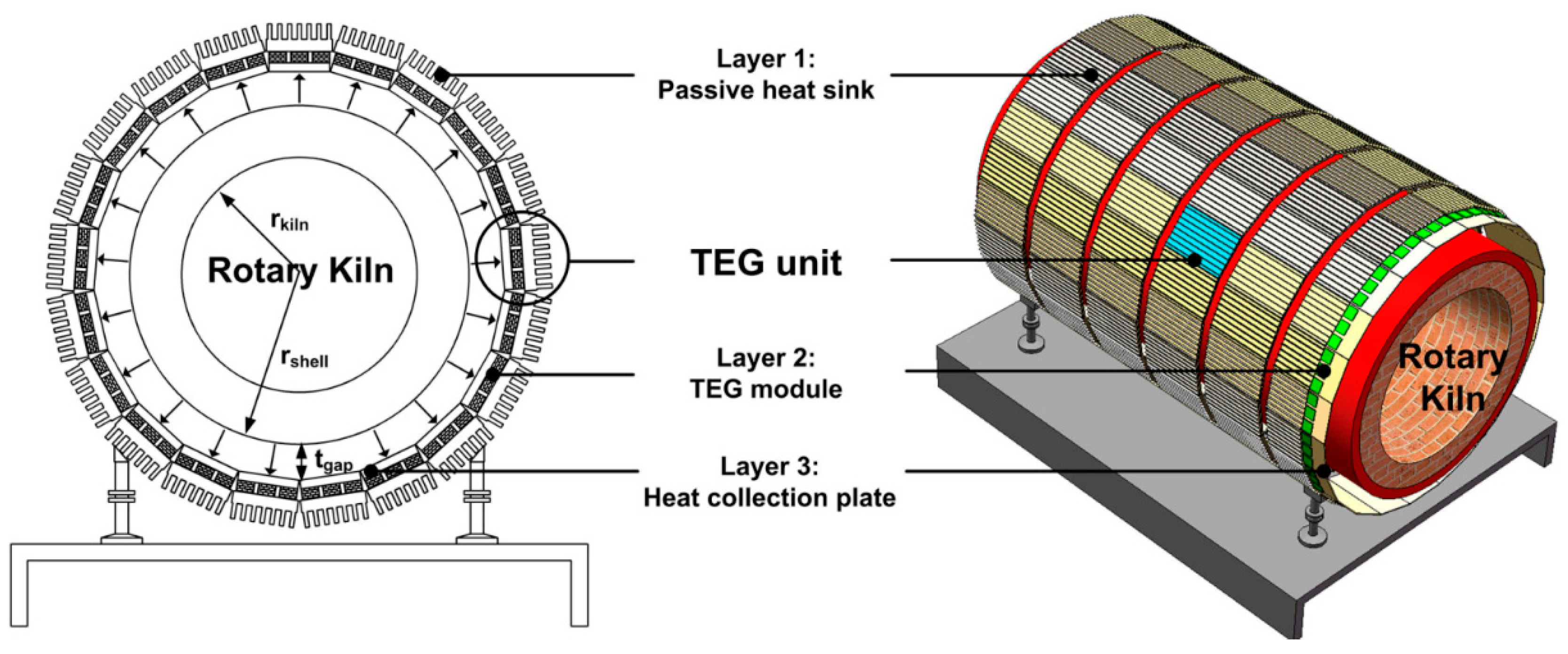
Luo et al. have also [93] developed a mathematical model for estimating the performance of waste heat recycling by thermoelectric generators from a cement rotary kiln with a diameter of 4.8 m and a length of 72 m (see Figure 13).
The results showed that a thermoelectric generator fabricated based on Bi2Te3–PbTe hybrid thermoelectric materials can generate about 211 kW electrical power to save 3283 kW thermal energy. Furthermore, the kiln integrated with this TEG system was estimated to be approximately 33% of the wasted energy compared to a kiln with no thermoelectric recovery system.
Another example is the application of TEG for waste heat recovery systems emitted from the surface of the rotary kiln performed for the Rudniki cement industrial plant [99]. In this work, the mentioned recovery system was designed for a rotary cement kiln with a length of 16–28 m. The studied TEG design generated a power output in the range of 1.46 kW to ~11 kW, corresponding to the received radiation heat of 10 kWh and 163 kWh, respectively, depending on the distance of the TEG system from the kiln surface. The maximum energy generated by the designed TEG was reported as 163 kWh and 11 kW when the system was installed at a distance of 1 m from the rotary kiln surface. According to the discussion, since the cement industry has high energy consumption, resulting in waste heat and generated GHGs emissions and, thus, adverse environmental impacts, a TEG recovery system can potentially reduce energy consumption and reduce the harmful gases into the atmosphere. However, several essential strategies must be considered before installing a TEG system on the rotary kiln surfaces, as follows:
- It is necessary to assess the surface temperature balance along the rotary kiln length to reduce side effects on the quality of the final products and the kiln service life (e.g., elimination of crack formation on the kiln shell due to hot spots)
- Optimizing the distance of the TEG system to the rotary kiln
- TEGs should not be installed directly on the kiln surface because they can increase the weight of the kiln and, thus, require more energy to rotate. Moreover, the direct installation of TEGs on the kiln surface adds a thermal resistance layer to the outer surface.
The achievements mentioned above in regard to waste heat recycling from a cement rotary kiln are just some examples of the application of thermometric generators for industrial waste heat recovery. However, many more industrial sectors, such as concentrated solar plants, steel industries, and other industrial sectors, produce heat as a by-product and can be the subject of experimental and field-test evaluations of the performance of thermoelectric heat recovery systems.
6. Challenges and Opportunities
As previously mentioned, TEGs can convert waste heat into electrical energy. Such capability should enable a reduction in fossil fuel consumption and decrease GHGs emissions to some extent. Compared with conventional generators using fossil fuels, the main challenge of TEGs is their low work efficiency, which is directly related to TE materials. Therefore, there are challenges in developing new and more advanced TE materials with larger zT factors. This is now the main drive in R&D activities in laboratories worldwide [31,32,66,92]. In addition to the development of new materials, the architecture of TEGs and their ability to adapt with the geometrical variations when TEGs come in contact with surfaces, where there is a temperature gradient, is a further challenge faced by the TE community. The selection of materials for the body of TEGs introduces some new constraints. In addition to flexibility in adapting different shapes, they have to be good thermal conductors to transfer waste heat to TE materials. Another challenge faced by the TE community is the cost of TEGs, which is attributed to the cost of currently available TE materials and the employed fabrication route, which is mainly based on powder metallurgy. The introduction of additive manufacturing and processes such as powder bed fusion using a laser (L-PBF) or electron beam (E-PBF) as the primary source of input energy or direct energy deposition, DED, could provide some solutions for reducing cost. However, despite such challenges, the advent and introduction of TEGs provide some opportunities to further advance our societies with better access to health, information and monitoring through the introduction of advanced sensors, vibration-free cooling, and heating systems, to name just a few. As mentioned before, the most pronounced opportunity for using TEGs is to reduce the consumption of fossil fuels. TEGs use waste heat to produce electrical energy rather than burning extra fossil fuels for a specific energy output or the requirement of a complex infrastructure (e.g., solar and wind power plants) for collecting the thermal energy and converting it into electricity. Furthermore, TEGs are not weather or daytime-dependent, as in photo voltaic-based energy generators where solar energy is the vital ingredient. Furthermore, TEGs can be installed in various orientations with no impact on their performances.
Moreover, in some particular applications, such as NASA missions [26,27] outside the earth where there is no access to solar energy or in highly sensitive to vibration instruments, such as the Hubble telescope (e.g., in solid dewar) [100], TE devices are the only options. Indeed, TE devices are the preferred options if reliability or accuracy matters more than efficiency. These features have opened a wide range of applications for TE devices, specifically for low-temperature applications, such as wearable TEGs and thermoelectric cooling systems in medical practices [101]. Self-powered wearable electronics are expected to become more extended and advanced from the wrist and into textiles in people’s daily lives [102,103]. Given the immense research and vast commercial prospects in self-powered wearable electronics, new near-term advancements are expected. In parallel, the market for self-powered wearable electronics is likely to continue its fast developments and retain its strategy to improve and modify people’s lives.
7. Conclusions
The current research presented an overview of the trends in energy management, emphasizing waste heat recovery by TEGs. It is claimed the new TE-based technology will produce clean energy and reduce fossil fuel consumption through recycling waste heat.
Direct advantages achieved by introducing heat recycling technology can lead to a substantial advancement in energy consumption efficiency. In addition, heat recycling technology can recover part of the waste heat and significantly reduce greenhouse gas emissions and enhance public health with better sustainability. In this approach, thermoelectric generators enable the industries to capture waste heat and recycle it by direct conversion into electrical energy. Furthermore, the simplicity of thermoelectric generators with no mechanical parts has extended their applications to a range of situations where vibration is a hurdle, such as precision positioning in medicine or photography, as in the case of the Hubble telescope. In addition, the advent of new TE materials has enabled various industries to benefit from energy recovery and recycling, where specifically heat is produced with a temperature of several hundred degrees as a by-product. In order to better highlight the requirements for the introduction of waste heat recovery and recycling, we provided a brief account of the science of TE materials to emphasize further the need for more development of advanced TE materials. Finally, as a case study, recent attempts in the successful application and performance of TEGs to recover waste heat emitted from rotary cement kilns have been discussed. However, due to the growing need of industrial sectors to employ waste heat recycling systems and save energy and costs, more experimental and field tests are still required to commercialize TEG recovery systems.
Author Contributions
Conceptualization, S.H.Z., R.G. and M.J.; formal analysis, S.H.Z.; investigation, S.H.Z.; resources, S.H.Z.; data curation, S.H.Z.; writing—original draft preparation, S.H.Z.; writing—review and editing, S.H.Z., R.G., D.V. and M.J.; supervision, R.G. and D.V.; funding acquisition, R.G. and D.V. All authors have read and agreed to the published version of the manuscript.
Funding
This research was funded by Australian Research Council, “The ARC Graphene Enabled Industry Transformation Hub” under grant number IH150100003 and the National Science Foundation (NSF) under grant numbers ECCS-1711253 and CBET-2110603.
Institutional Review Board Statement
This research does not induct any study involving humans or animals.
Informed Consent Statement
Not applicable.
Data Availability Statement
Not applicable.
Acknowledgments
This work has been supported by the Australian Government Research Training Program Scholarship, the ARC Graphene Enabled Industry Transformation Hub at the University of Adelaide, and the National Science Foundation (NSF) at North Carolina State University.
Conflicts of Interest
There are no conflict of interest to declare.
References
- Geoff, M.; Saikawa, E. Effectiveness of state climate and energy policies in reducing power-sector CO2 emissions. Nat. Clim. Chang. 2017, 7, 912–919. [Google Scholar]
- Yusaf, T.; Goh, S.; Borserio, J.A. Potential of renewable energy alternatives in Australia. Renew. Sustain. Energy Rev. 2011, 15, 2214–2221. [Google Scholar] [CrossRef]
- Available online: https://flowcharts.llnl.gov/content/assets/docs/2019_United-States_Energy.pdf (accessed on 15 March 2021).
- Annual Energy Outlook 2020 with Projections to 2050. January 2020; U.S. Energy Information Administration Office of Energy Analysis, U.S. Department of Energy, Washington, DC, USA; Available online: https://www.eia.gov/ or https://www.eia.gov/outlooks/aeo/pdf/AEO2020%20Full%20Report.pdf; (accessed on 15 March 2021).
- Yang, J.; Stabler, F.R. Automotive Applications of Thermoelectric Materials. J. Electron. Mater. 2009, 38, 1245–1251. [Google Scholar] [CrossRef]
- Ando Junior, O.H.; Maran, A.L.O.; Henao, N.C. A review of the development and applications of thermoelectric microgenerators for energy harvesting. Renew. Sustain. Energy Rev. 2018, 91, 376–393. [Google Scholar] [CrossRef]
- Zhang, Y. Thermoelectric Advances to Capture Waste Heat in Automobiles. ACS Energy Lett. 2018, 3, 1523–1524. [Google Scholar] [CrossRef]
- Ding, L.C.; Akbarzadeh, A.; Tan, L. A review of power generation with thermoelectric system and its alternative with solar ponds. Renew. Sustain. Energy Rev. 2018, 81, 799–812. [Google Scholar] [CrossRef]
- Polozine, A.; Sirotinskaya, S.; Schaeffer, L. History of Development of Thermoelectric Materials for Electric Power Generation and Criteria of their Quality. Mater. Res. Soc. 2014, 17, 1260–1267. [Google Scholar] [CrossRef] [Green Version]
- Taroni, P.J.; Hoces, I.; Stingelin, N.; Heeney, M.; Bilotti, E. Thermoelectric Materials: A Brief Historical Survey from Metal Junctions and Inorganic Semiconductors to Organic Polymers. Isr. J. Chem. 2014, 54, 534–552. [Google Scholar] [CrossRef]
- Zaferani, S.H. Improvement of Thermoelectric Properties through Manipulation of Their Microstructure: The Effect of Graphene Reinforcement. Ph.D. Thesis, The University of Adelaide, Adelaide, Australia, 2021. [Google Scholar]
- Mena, J.M.; Schoberth, H.G.; Gruhn, T.; Emmerich, H. Ab initio study of domain structures in half-metallic CoTi1-xMnxSb and thermoelectric CoTi1-xScxSb half-Heusler alloys. J. Alloy. Compd. 2015, 650, 728–740. [Google Scholar] [CrossRef]
- Punith, N.; Swamy, G.M.; Yalagi, S. A Thermoelectric Generator Systems Forwaste Heat Recovery—A Review. Int. J. Eng. Res. Technol. 2015, 3, 110–171. [Google Scholar]
- Brief History of Thermoelectrics, Northwestern Materials Science and Engineering. Available online: http://thermoelectrics.matsci.northwestern.edu/thermoelectrics/history.html (accessed on 15 March 2021).
- Thermoelectrics History Timeline, Copyright © 2009–2020, Alphabet Energy, Inc. Available online: http://www.alphabetenergy.com/thermoelectrics-timeline/ (accessed on 15 March 2021).
- Kee, S.; Haque, M.A.; Lee, Y.; Nguyen, T.L.; Villalva, D.R.; Troughton, J.; Emwas, A.; Alshareef, H.N.; Woo, H.Y.; Baran, D. A Highly Conductive Conjugated Polyelectrolyte for Flexible Organic Thermoelectrics. ACS Appl. Energy Mater. 2020, 3, 8667–8675. [Google Scholar] [CrossRef]
- Ekubaru, Y.; Sugahara, T.; Ibano, K.; Suetake, A.; Tsurumoto, M.; Kagami, N.; Suganuma, K. Fabrication and Characterization of Ultra-Lightweight, Compact, and Flexible Thermoelectric Device Based on Highly Refined Chip Mounting. Adv. Mater. Technol. 2020, 5, 1901128. [Google Scholar] [CrossRef]
- Bisht, N.; More, P.; Khanna, P.K.; Abolhassani, R.; Mishra, Y.K.; Madsen, M. Progress of hybrid nanocomposite materials for thermoelectric applications. Mater. Adv. 2021, 2, 1927. [Google Scholar] [CrossRef]
- Allison, L.K.; Andrew, T.L. A Wearable All-Fabric Thermoelectric Generator. Adv. Mater. Technol. 2019, 4, 1800615. [Google Scholar] [CrossRef]
- Available online: https://0-spectrum-ieee-org.brum.beds.ac.uk/a-thermoelectric-generator-for-wearable-tech#toggle-gdpr (accessed on 16 June 2020).
- Massaguer, A.; Pujol, T.; Comamala, M.; Massaguer, E. Feasibility study on a vehicular thermoelectric generator coupled to an exhaust gas heater to improve aftertreatment’s efficiency in cold-starts. Appl. Therm. Eng. 2020, 167, 114702. [Google Scholar] [CrossRef]
- Chang, C.; Wang, Z.; Fu, B.; Ji, Y. High-efficiency solar thermoelectric conversion enabled by movable charging of molten salts. Sci. Rep. 2020, 10, 20500. [Google Scholar] [CrossRef] [PubMed]
- Available online: https://solarsystem.nasa.gov/missions/cassini/radioisotope-thermoelectric-generator/ (accessed on 16 June 2021).
- Available online: https://mars.nasa.gov/mars2020/spacecraft/rover/electrical-power/ (accessed on 16 June 2021).
- Yahyaoglu, M.; Ozen, M.; Prots, Y.; El Hamouli, O.; Tshitoyan, V.; Ji, H.; Burkhardt, U.; Lenoir, B.; Snyder, G.J.; Jain, A.; et al. Phase-Transition-Enhanced Thermoelectric Transport in Rickardite Mineral Cu3−xTe2. Chem. Mater. 2021, 33, 1832–1841. [Google Scholar] [CrossRef]
- Sun, T.; Zhou, B.; Zheng, Q.; Wang, L.; Jiang, W.; Snyder, G.J. Stretchable fabric generates electric power from woven thermoelectric fibers. Nat. Commun. 2020, 11, 572. [Google Scholar] [CrossRef]
- Kim, M.; Kim, M.; Lee, S.; Kim, C.; Kim, Y. Wearable thermoelectric generator for harvesting human body heat energy. Smart Mater. Struct. 2014, 23, 105002. [Google Scholar] [CrossRef]
- Zaferani, S.H.; Ghomashchi, R.; Vashaee, D. An Assessment of Thermoelectric, Mechanical and Microstructural Reinforcement Properties of Graphene-mixed Heterostructures. ACS Appl. Energy Mater. 2021, 4, 3573–3583. [Google Scholar] [CrossRef]
- Zaferani, S.H.; Darebaghi, A.; Hong, S.; Vashaee, D.; Ghomashchi, R. Experimental Realization of Heavily p-doped Half-Heusler CoVSn Compound. Energies 2020, 13, 1459. [Google Scholar] [CrossRef] [Green Version]
- Usman, M.; Kim, I.-H.; Jung, H.-J. Improving thermoelectric energy harvesting efficiency by using graphene. AIP Adv. 2016, 6, 1–7. [Google Scholar] [CrossRef] [Green Version]
- Falmbigl, M.; Rogi, G.; Rogl, P.; Kriegisch, M.; Müller, H.; Bauer, E.; Reinecker, M.; Schranz, W. Thermal expansion of thermoelectric type-I-clathrates. J. Appl. Phys. 2010, 108, 043529. [Google Scholar] [CrossRef]
- Kishimoto, K.; Sasaki, Y.; Koyanagi, T.; Ohoyama, K.; Akai, K. Crystal structure and thermoelectric properties of KxBa82xZnyGe462y clathrates. J. Appl. Phys. 2012, 111, 1–8. [Google Scholar] [CrossRef] [Green Version]
- Kleinke, H. New bulk Materials for Thermoelectric Power Generation: Clathrates and Complex Antimonides. Chem. Mater. 2010, 22, 604–611. [Google Scholar] [CrossRef]
- Qiu, P.F.; Liu, R.H.; Yang, J.; Shi, X.; Huang, X.Y.; Zhang, W.; Chen, L.D.; Yang, J.; Singh, D.J. Thermoelectric properties of Ni-doped CeFe4Sb12 skutterudites. J. Appl. Phys. 2012, 111, 1–7. [Google Scholar] [CrossRef]
- Mallik, R.C.; Anbalagan, R.; Raut, K.K.; Bali, A.; Royanian, E.; Bauer, E.; Rogl, P.; Rogl, G. Thermoelectric properties of Bi-added Co4Sb12 skutterudites. J. Phys. Condens. Matter 2013, 25, 105701. [Google Scholar] [CrossRef]
- Dong, Y.; Puneet, P.; Tritt, T.M.; Martin, J.; Nolas, G.S. High temperature thermoelectric properties of p-type skutterudites BaxYbyCo4-zFezSb12. J. Appl. Phys. 2012, 112, 1–5. [Google Scholar] [CrossRef]
- Cho, J.Y.; Ye, Z.; Tessema, M.M.; Waldo, R.A.; Salvador, J.R.; Yang, J.; Cai, W.; Wang, H. Thermoelectric properties of p-type skutterudites YbxFe3.5Ni0.5Sb12 (0.8 < x < 1). Acta Mater. 2012, 60, 2104–2110. [Google Scholar]
- Oudah, M.; Kleinke, K.M.; Kleinke, H. Thermoelectric Properties of the Quaternary Chalcogenides BaCu5.9STe6 and BaCu5.9SeTe6. Inorg. Chem. 2015, 54, 845–849. [Google Scholar] [CrossRef]
- Ge, X.-J.; Qin, D.; Yao, K.-L.; Lü, J.-T. First-principles study of thermoelectric transport properties of monolayer gallium chalcogenides. J. Phys. D Appl. Phys. 2017, 50, 1–6. [Google Scholar] [CrossRef]
- Kastbjerg, S.; Bindzus, N.; Søndergaard, M.; Johnsen, S.; Lock, N.; Christensen, M.; Takata, M.; Spackman, M.A.; Iversen, B.B. Direct Evidence of Cation Disorder in Thermoelectric Lead Chalcogenides PbTe and PbS. Adv. Funct. Mater. 2013, 23, 5477–5483. [Google Scholar] [CrossRef]
- Tavassoli, A.; Failamani, F.; Grytsiv, A.; Rogl, G.; Heinrich, P.; Müller, H.; Bauer, E.; Zehetbauer, M.; Rogl, P. On the Half-Heusler compounds Nb1-x{Ti,Zr,Hf}xFeSb: Phase relations, thermoelectric properties at low and high temperature, and mechanical properties. Acta Mater. 2017, 135, 263–276. [Google Scholar] [CrossRef]
- Yamamoto, A.; Takeuchi, T. The Potential of FeVSb Half-Heusler Phase for Practical Thermoelectric Material. J. Electron. Mater. 2017, 46, 3200–3206. [Google Scholar] [CrossRef]
- Yan, F.; Zhang, X.; Yu, Y.G.; Yu, L.; Nagaraja, A.; Mason, T.O.; Zunger, A. Design and discovery of a novel half-Heusler transparent hole conductor made of all-metallic heavy elements. Nat. Commun. 2015, 6, 1–8. [Google Scholar] [CrossRef]
- Zhang, H.; Wang, Y.; Dahal, K.; Mao, J.; Huang, L.; Zhang, Q.; Ren, Z. Thermoelectric properties of n-type half-Heusler compounds (Hf0.25Zr0.75)1exNbxNiSn. Acta Mater. 2016, 113, 41–47. [Google Scholar] [CrossRef] [Green Version]
- Yu, J.; Xia, K.; Zhao, X.; Zhu, T. High performance p-type half-Heusler thermoelectric materials. J. Phys. D Appl. Phys. 2018, 51, 1–15. [Google Scholar] [CrossRef]
- Kaller, M.; Fuks, D.; Gelbstein, Y. Sc solubility in p-type half-Heusler (Ti1-cScc)NiSn thermoelectric alloys. J. Alloy. Compd. 2017, 729, 446–452. [Google Scholar] [CrossRef]
- Zeier, W.G.; Schmitt, J.; Hautier, G.; Aydemir, U.; Gibbs, Z.M.; Felser, C.; Snyder, G.J. Engineering half-Heusler thermoelectric materials using Zintl chemistry. Nat. Rev. Mater. 2016, 1, 1–10. [Google Scholar] [CrossRef]
- Zeeshan, M.; Singh, H.K.; Brink, J.; Kandpal, H.C. Ab initio design of new cobalt-based half-Heusler materials for thermoelectric applications. Phys. Rev. Mater. 2017, 1, 075407-1–075407-9. [Google Scholar] [CrossRef] [Green Version]
- Yang, L.; Chen, Z.; Dargusch, M.S.; Zou, J. High Performance Thermoelectric Materials: Progress and Their Applications. Adv. Energy Mater. 2018, 8, 1–28. [Google Scholar] [CrossRef]
- Fairbanks, J. Thermoelectric Applications in Vehicles Status 2008; U.S. Department of Energy: Washington, DC, USA, 2008; p. 20585.
- Photo Courtesy of NASA/JPLCaltech. Available online: https://www.energy.gov/sites/prod/files/styles/borealis_photo_gallery_large_respondsmall/public/mars_rover_MMGTG_0.png?itok=8S2HxJhI (accessed on 16 June 2021).
- Kraemer, D.; Poudel, B.; Feng, H.-P.; Caylor, J.C.; Yu, B.; Yan, X.; Ma, Y.; Wang, X.; Wang, D.; Muto, A.; et al. High-performance flat-panel solar thermoelectric generators with high thermal concentration. Nat. Mater. 2011, 10, 532–538. [Google Scholar] [CrossRef] [PubMed]
- Zhou, J.; Shin, H.D.; Chen, K.; Song, B.; Duncan, R.A.; Xu, Q.; Maznev, A.A.; Nelson, K.A.; Chen, G. Direct observation of large electron–phonon interaction effect on phonon heat transport. Nat. Commun. 2020, 11, 6040. [Google Scholar] [CrossRef]
- Qin, F.; Nikolaev, S.A.; Suwardi, A.; Wood, M.; Zhu, Y.; Tan, X.; Aydemir, U.; Ren, Y.; Yan, Q.; Hu, L.; et al. Crystal Structure and Atomic Vacancy Optimized Thermoelectric Properties in Gadolinium Selenides. Chem. Mater. 2020, 32, 10130–10139. [Google Scholar] [CrossRef]
- Maoa, J.; Shuaia, J.; Songa, S.; Wu, Y.; Dally, R.; Zhou, J.; Liu, Z.; Sun, J.; Zhang, Q.; Cruz, C.D.; et al. Manipulation of ionized impurity scattering for achieving high thermoelectric performance in n-type Mg3Sb2-based materials. Proc. Natl. Acad. Sci. USA 2017, 114, 10548–10553. [Google Scholar] [CrossRef] [PubMed] [Green Version]
- Lu, R.; Olvera, A.; Bailey, T.; Fu, J.; Su, X.; Veremchuk, I.; Yin, Z.; Buchannan, B.; Uher, C.; Tang, X.; et al. High carrier mobility and ultralow thermal conductivity in the synthetic layered superlattice Sn4Bi10Se19. Mater. Adv. 2021, 2, 2382–2390. [Google Scholar] [CrossRef]
- Zaferani, S.H. Using Silane Products on Fabrication of Polymer-Based Nanocomposite for Thin Film Thermoelectric Devices. Renew. Sustain. Energy Rev. 2017, 71, 359–364. [Google Scholar] [CrossRef]
- Dresselhaus, M.S.; Chen, G.; Tang, M.Y.; Yang, R.; Lee, H.; Wang, D.; Ren, Z.; Fleurial, J.-P.; Gogna, P. New Directions for Low-Dimensional Thermoelectric Materials. Adv. Mater. 2007, 19, 1043–1053. [Google Scholar] [CrossRef]
- Norouzzadeh, P.; Ede, K.F.; Vashaee, D. The effect of nanostructuring on the spectral population of electrons and phonons. J. Alloy. Compd. 2018, 753, 234–238. [Google Scholar] [CrossRef]
- Satyala, A.N.; Norouzzadeh, P.; Vashaee, D. Nano Bulk Thermoelectrics: Concepts, Techniques, and Modeling, Nanoscale Thermoelectrics; Springer: Berlin/Heidelberg, Germany, 2014; pp. 141–183. [Google Scholar]
- Zamanipour, Z.; Shi, X.; Dehkordi, A.M.; Krasinski, J.S.; Vashaee, D. The effect of synthesis parameters on transport properties of nanostructured bulk thermoelectric p-type silicon germanium alloy. Phys. Status Solidi 2012, 209, 2049–2058. [Google Scholar] [CrossRef]
- Bao, D.; Chen, J.; Yu, Y.; Liu, W.; Huang, L.; Han, G.; Tang, J.; Zhou, D.; Yang, L.; Chen, Z.-G. Texture-dependent thermoelectric properties of nano-structured Bi2Te3. Chem. Eng. J. 2020, 388, 124295. [Google Scholar] [CrossRef]
- Zaferani, S.H.; Ghomashchi, R.; Vashaee, D. Thermoelectric, Magnetic, and Mechanical Characteristics of Antiferromagnetic Manganese Telluride Reinforced with Graphene Nanoplates. Adv. Eng. Mater. 2021, 13, 2000816. [Google Scholar] [CrossRef]
- Beretta, D.; Neophytou, N.; Hodges, J.M.; Kanatzidis, M.G.; Narducci, D.; Gonzalez, M.M.; Beekman, M.; Balke, B.; Cerretti, G.; Tremel, W.; et al. Thermoelectrics: From history, a window to the future. Mater. Sci. Eng. R Rep. 2019, 138, 100501. [Google Scholar] [CrossRef]
- Ying, P.; He, R.; Mao, J.; Zhang, Q.; Reith, H.; Sui, J.; Ren, Z.; Nielsch, K.; Schierning, G. Towards tellurium-free thermoelectric modules for power generation from low-grade heat. Nat. Commun. 2021, 12, 1121. [Google Scholar] [CrossRef] [PubMed]
- Sarkar, S.; Hua, X.; Hao, S.; Zhang, X.; Bailey, T.P.; Slade, T.J.; Yasaei, P.; Korkosz, R.J.; Tan, G.; Uher, C.; et al. Dissociation of GaSb in n-Type PbTe: Off-Centered Gallium Atom and Weak Electron−Phonon Coupling Provide High Thermoelectric Performance. Chem. Mater. 2021, 33, 1842–1851. [Google Scholar] [CrossRef]
- Malhotra, A.; Hosseini, M.; Zaferani, S.H.; Hall, M.; Vashaee, D. Enhancement of Diffusion, Densification and Solid-State Reaction in Dielectric Materials due to Interfacial Interaction of Microwave Radiation: Theory and Experiment. ACS Appl. Mater. Interfaces 2020, 12, 50941–50952. [Google Scholar] [CrossRef]
- Ahiska, R.; Yavuz, A.H.; Kaymaz, M.; Güler, İ. Control of a Thermoelectric Brain Cooler by Adaptive Neuro-Fuzzy Inference System. Instrum. Sci. Technol. 2008, 36, 636–655. [Google Scholar] [CrossRef]
- Pei, Y.; Wang, H.; Snyder, G.J. Band Engineering of Thermoelectric Materials. Adv. Mater. 2012, 24, 6125–6135. [Google Scholar] [CrossRef]
- Heremans, J.P.; Jovovic, V.; Toberer, E.S.; Saramat, A.; Kurosaki, K.; Charoenphakdee, A.; Yamanaka, S.; Snyder, G.J. Enhancement of Thermoelectric Efficiency in PbTe by Distortion of the Electronic Density of States. Science 2008, 321, 554–557. [Google Scholar] [CrossRef] [Green Version]
- Heremans, J.P.; Wiendlocha, B.; Chamoire, A.M. Resonant levels in bulk thermoelectric semiconductors. Energy Environ. Sci. 2012, 5, 5510. [Google Scholar] [CrossRef]
- Wang, H.; Cao, X.; Takagiwa, Y.; Snyder, G.J. Higher mobility in bulk semiconductors by separating the dopants from the chargeconducting band—A case study of thermoelectric PbSe. Mater. Horiz. 2015, 2, 323. [Google Scholar] [CrossRef] [Green Version]
- Kumarasinghe, C.; Neophytou, N. Band alignment and scattering considerations for enhancing the thermoelectric power factor of complex materials: The case of Co-based half-Heusler alloys. Phys. Rev. B 2019, 99, 195202. [Google Scholar] [CrossRef] [Green Version]
- Pan, Y.; Fan, F.-R.; Hong, X.; He, B.; Le, C.; Schnelle, W.; He, Y.; Imasato, K.; Borrmann, H.; Hess, C.; et al. Thermoelectric Properties of Novel Semimetals: A Case Study of YbMnSb2. Adv. Mater. 2021, 33, 2003168. [Google Scholar] [CrossRef]
- Norouzzadeh, P.; Vashaee, D. Classification of valleytronics in thermoelectricity. Sci. Rep. 2016, 6, 22724. [Google Scholar] [CrossRef] [Green Version]
- Norouzzadeh, P.; Myles, C.W.; Vashaee, D. Prediction of a large number of electron pockets near the band edges in type-VIII clathrate Si46 and its physical properties from first principles. J. Phys. Condens. Matter 2013, 25, 475502. [Google Scholar] [CrossRef] [PubMed] [Green Version]
- Norouzzadeh, P.; Myles, C.W.; Vashaee, D. Electronic, elastic, vibrational, and thermodynamic properties of type-VIII clathrates Ba8Ga16Sn30 and Ba8Al16Sn30 by first principles. J. Appl. Phys. 2013, 114, 163509. [Google Scholar] [CrossRef]
- Snyder, G.J.; Toberer, E.S. Complex thermoelectric materials. Nat. Mater. 2008, 7, 105–114. [Google Scholar] [CrossRef] [PubMed]
- Norouzzadeh, P.; Myles, C.W.; Vashaee, D. Prediction of Giant Thermoelectric Power Factor in Type-VIII Clathrate Si46. Sci. Rep. 2014, 4, 7028. [Google Scholar] [CrossRef] [PubMed] [Green Version]
- Vashaee, D.; Shakouri, A. Nonequilibrium Electrons and Phonons in Thin Film Thermionic Coolers. Microscale Thermophys. Eng. 2004, 8, 91–100. [Google Scholar] [CrossRef]
- Zamanipour, Z.; Vashaee, D. Comparison of thermoelectric properties of p-type nanostructured bulk Si0.8Ge0.2 alloy with Si0.8Ge0.2 composites embedded with CrSi2 nano-inclusisons. J. Appl. Phys. 2012, 112, 093714. [Google Scholar] [CrossRef]
- Vashaee, D.; Zhang, Y.; Shakouri, A.; Zeng, G.; Chiu, Y.J. Cross-plane Seebeck coefficient in superlattice structures in the miniband conduction regime. Phys. Rev. B 2006, 74, 195315. [Google Scholar] [CrossRef] [Green Version]
- Vashaee, D.; Shakouri, A. HgCdTe superlattices for solid-state cryogenic refrigeration. Appl. Phys. Lett. 2006, 88, 132110. [Google Scholar] [CrossRef] [Green Version]
- Polash, M.M.H.; Vashaee, D. Magnon-bipolar carrier drag thermopower in antiferromagnetic/ferromagnetic semiconductors: Theoretical formulation and experimental evidence. Phys. Rev. B 2020, 102, 045202. [Google Scholar] [CrossRef]
- Zheng, Y.; Lu, T.; Polash, M.M.H.; Rasoulianboroujeni, M.; Liu, N.; Manley, M.E.; Deng, Y.; Sun, P.J.; Chen, X.L.; Hermann, R.P.; et al. Paramagnon drag in high thermoelectric figure of merit Li-doped MnTe. Sci. Adv. 2019, 5, eaat9461. [Google Scholar] [CrossRef] [PubMed] [Green Version]
- Paul, B.; Kumar, A.; Banerji, P. Embedded Ag-rich nanodots in PbTe: Enhancement of thermoelectric properties through energy filtering of the carriers. J. Appl. Phys. 2010, 108, 064322. [Google Scholar] [CrossRef]
- Li, Z.-Y.; Li, J.-F.; Zhao, W.-Y.; Tan, Q.; Wei, T.-R.; Wu, C.-F.; Xing, Z.-B. PbTe-based thermoelectric nanocomposites with reduced thermal conductivity by SiC nanodispersion. Appl. Phys. Lett. 2014, 104, 113905. [Google Scholar] [CrossRef]
- Zaferani, S.H.; Ghomashchi, R.; Vashaee, D. Strategies for engineering phonon transport in Heusler thermoelectric compounds. Renew. Sustain. Energy Rev. 2019, 112, 158–169. [Google Scholar] [CrossRef]
- Li, J.; Hao, S.; Qu, S.; Wolverton, C.; Zhao, J.; Wang, Y. In4Pb5.5Sb5S19: A Stable Quaternary Chalcogenide with Low Thermal Conductivity. Inorg. Chem. 2021, 60, 325–333. [Google Scholar] [CrossRef]
- Xie, L.; Feng, J.H.; Li, R.; He, J.Q. First-Principles Study of Anharmonic Lattice Dynamics in Low Thermal Conductivity AgCrSe2: Evidence for a Large Resonant Four-Phonon Scattering. Phys. Rev. Lett. 2020, 125, 245901. [Google Scholar] [CrossRef]
- Sztekler, K.; Komorowski, M.; Tarnowska, M.; Posak, Ł. Utilization of waste heat from rotary kiln for burning clinker in the cement plant. In Proceedings of the 1st International Conference on the Sustainable Energy and Environment Development (SEED 2016), E3S Web Conference, 17 October 2016; Volume 10. [Google Scholar] [CrossRef] [Green Version]
- Ismailov, T.A.; Yevdulov, O.V.; Khazamova, M.A.; Gidurimova, D.A. Experimental Investigations of Thermoelectric Device for the Therapy of Whitlow. J. Thermoelectr. 2013, 4, 78–84. [Google Scholar]
- Luo, Q.; Li, P.; Cai, L.; Zhou, P.; Tang, D.; Zhai, P.; Zhang, Q. A Thermoelectric Waste-Heat-Recovery System for Portland Cement Rotary Kilns. J. Electron. Mater. 2015, 44, 1750–1762. [Google Scholar] [CrossRef]
- Wu, W.-N.; Liu, X.-Y.; Hu, Z.; Zhang, R.; Lu, X.-Y. Improving the sustainability of cement clinker calcination process by assessing the heat loss through kiln shell and its influencing factors: A case study in China. J. Clean. Prod. 2019, 224, 132–141. [Google Scholar] [CrossRef]
- Mirhosseini, M.; Rezania, A.; Rosendahl, L. Harvesting waste heat from cement kiln shell by thermoelectric system. Energy 2019, 168, 358–369. [Google Scholar] [CrossRef]
- Mirhosseini, M.; Rezania, A.; Rosendahl, L. Power optimization and economic evaluation of thermoelectric waste heat recovery system around a rotary cement kiln. J. Clean. Prod. 2019, 232, 1321–1334. [Google Scholar] [CrossRef]
- Mirhosseini, M.; Rezaniakolaei, A.; Rosendahl, L. Numerical Study on Heat Transfer to an Arc Absorber Designed for a Waste Heat Recovery System around a Cement Kiln. Energies 2018, 11, 671. [Google Scholar] [CrossRef] [Green Version]
- Hsu, C.-T.; Won, C.-C.; Chu, H.-S.; Hwang, J.-D. A case study of thermoelectric generator application on rotary cement furnace. In Proceedings of the 8th International Conference on Microsystems, Packaging, Assembly and Circuits Technology (IMPACT), Taipei, Taiwan, 22–25 October 2013. [Google Scholar] [CrossRef]
- Sztekler, K.; Wojciechowski, K.; Komorowski, M.; Tarnowska, M. The thermoelectric generators use for waste heat utilization from cement plant. In E3S Web of Conferences; EDP Sciences: Les Ulis, France, 2017; Volume 14, p. 01031. [Google Scholar] [CrossRef]
- Mills, G.L.; Kelly, T.K.; Brown, B. Integration of Thermoelectric Coolers into a Solid Nitrogen Dewar. Adv. Cryog. Eng. 1996, 41, 1121–1128. [Google Scholar]
- Tang, Y.; Li, X.; Lv, H.; Wang, W.; Zhi, C.; Li, H. Integration designs toward new-generation wearable energy supply-sensor systems for real-time health monitoring: A minireview. InfoMat 2020, 2, 1109–1130. [Google Scholar] [CrossRef]
- Lee, B.; Cho, H.; Park, K.T.; Kim, J.-S.; Park, M.; Kim, H.; Hong, Y.; Chung, S. High-performance compliant thermoelectric generators with magnetically self-assembled soft heat conductors for self-powered wearable electronics. Nat. Commun. 2020, 11, 5948. [Google Scholar] [CrossRef] [PubMed]
- Yuan, J.; Zhu, R.; Li, G. Self-Powered Electronic Skin with Multisensory Functions Based on Thermoelectric Conversion. Adv. Mater. Technol. 2020, 5, 2000419. [Google Scholar] [CrossRef]
Figure 1.
Energy flow diagram of the US energy production and consumption. Source: Lawrence Livermore National Laboratory [3].
Figure 1.
Energy flow diagram of the US energy production and consumption. Source: Lawrence Livermore National Laboratory [3].

Figure 2.
Electricity generation from selected energy resources, (a) fuel energies and (b) clean energies [4].
Figure 2.
Electricity generation from selected energy resources, (a) fuel energies and (b) clean energies [4].

Figure 3.
Application of renewable energies in the future [4].
Figure 3.
Application of renewable energies in the future [4].

Figure 4.
Energy-related emissions by the energy sector [4].
Figure 4.
Energy-related emissions by the energy sector [4].


Figure 6.
Recent decades: 21st century: (a) self-doped conjugated polyelectrolytes (CPEs) has been evaluated as a promising class of conductive organic for organic thermoelectrics (adapted from [16] with permission), (b) photograph of a prototype for a compact and flexible TEG (CF-TEG) using ultra-fine chip mounting technique. It is made of 84 p-n pairs fabricated on a 10 × 10 mm2 flexible substrate. It produced a maximum output voltage and power density of 2.4 V and 185 mWcm−2, respectively, at = 150 K (adapted from [17] with permission), (c) photograph of a flexible TEG prototype. It is fabricated by a locknit spacer fabric as the substrate and yarns are coated with waterborne polyurethane/carbon nanotube thermoelectric composites as legs (thermocouples), (adapted from [18] with permission), (d) body-heat harvester made with cotton. A vapor-deposited strip of cotton fabric-coated with p-doped poly(3,4-ethylenedioxythiophene) [19]. Photo source: IEEE spectrum [20], (e) an automotive thermoelectric generator (ATEG) is built and tested experimentally on the exhaust system of the engine cell (adapted from [21] with permission), (f) schematic illustration of the solar–thermal–electric conversion system (STECS) constructed by a movable charging solar–thermal storage and TE conversion subsystems. The magnet installed at the bottom of the solar–thermal storage subsystem is to make movable charging of the molten salts inside the container (adapted from [22] with permission), (g) installation of thermoelectric generator systems on the Cassini spacecraft, photo credit: NASA [23], and (h) NASA’s Mars 2020 rover is powered based on thermoelectric power generation [24].

Figure 7.
(a) Stem chart, which classifies the TE materials based on their optimum operating temperatures in three main intervals: low (Room temperature to 600 K), mid (600 to 850 K), and high (850 K and more) [49], (b) a list of TE compounds, and a TEG operating at room temperature, (c) illustrates the TE materials with the optimized application at medium temperatures, and (d) an application of TEGs in converting car exhaust heat into electricity [5,50], (e) represents the TE compounds with optimum performance at high temperatures, and (f) two examples of their applications by NASA [51], and Solar TEGs [52] (adapted from [8], with permission).

Figure 8.
SEM micrographs of the sintered (a) Bi2Te3 nanoparticles (BT-1), (b) Bi2Te3 thick nanoplates (BT-2), and (c) ultrathin Bi2Te3 nanosheets (BT-3). Temperature dependence of (d) electrical conductivity, and Seebeck coefficient, (e) lattice thermal conductivity, and power factor (adapted from [62] with permission).

Figure 9.
(a) Reinforcing MnTe by graphene nanoplates (GNPs) via powder metallurgy, (b) GNPs precipitation in the matrix (adapted from [63] with permission), (c) GNPs precipitation at microstructural barriers of CoVSn compound (adapted from [28] with permission), (d) schematic band alignment of Schottky contact for graphene/n-type semiconductor (adapted from [28] with permission), (e) schematic band alignment of Schottky contact for graphene/p-type semiconductor (adapted from [28] with permission), (f) schematic diagrams of hole trap, hole barrier, electron trap, and electron barrier generated at grain boundaries (adapted from [28] with permission).

Figure 10.
Schematic illustration of several sources of waste thermal energy and waste heat recycling by thermoelectric generators.
Figure 10.
Schematic illustration of several sources of waste thermal energy and waste heat recycling by thermoelectric generators.

Figure 11.
(a) A view of a cement rotary kiln in the Aalborg Portland cement factory, Aalborg, Denmark. Length 163 m, outer diameter: 3.6 m (adapted from [95] with permission), (b) temperature distribution along the kiln surface with a measurement interval of 2 m, inset: schematic illustration of the studied annular absorber (inset). The free stream air temperature (T∞) and corresponding velocity (U∞,) were considered as 5 °C and 5.86 m/s, respectively. The kiln rotational speed: 5 rpm (clockwise) (adapted from [95] with permission), (c) local heat loss through the kiln surface based on three heat transfer mechanisms, including free convection, forced convection, and radiation (adapted from [95] with permission), (d) schematic illustration of the 2D computational domain (adapted from [95] with permission), (e) one dimensional thermal equivalent electrical circuit (adapted from [95] with permission), (f) electrical resistance networks (adapted from [95] with permission), (g) schematic illustration of the thermoelectric unit on the panel (adapted from [95] with permission).

Figure 12.
(a) working cement kiln, outer diameter: 4.8 m and length: 76 m (adapted from [98] with permission), (b) thermoelectric power generation system containing 32 thermoelectric power generation units installed on a 2 × 1 m2 steel frame (adapted from [98] with permission), (c) output voltage as a function of current (adapted from [98] with permission), (d) power output as a function of load resistance (adapted from [98] with permission), (e) generated power with a matched load power of 214.3 W at the site (adapted from [98] with permission), and (f) generated power with a matched load power of 214.3 W in the control room to light up the indoor LED lamps (15 LED lamps × 10 W) (adapted from [98] with permission).

Figure 13.
Configuration of a thermoelectric waste heat recycling system for a Portland cement rotary kiln, length: 72 m, diameter: 4.8 m, (adapted from [93]).
Figure 13.
Configuration of a thermoelectric waste heat recycling system for a Portland cement rotary kiln, length: 72 m, diameter: 4.8 m, (adapted from [93]).


Table 1.
Optimum design characteristics for the TEG systems fabricated by Bi2Te3 and Zn4Sb3-based thermoelectric compounds [95].
Table 1.
Optimum design characteristics for the TEG systems fabricated by Bi2Te3 and Zn4Sb3-based thermoelectric compounds [95].
| Optimum Fill Factor | Optimum Leg Length (mm) | Optimum Power Output (W) | Optimum Power Output (W/m2) | Cost ($US) | Cost per Power ($US/W) | Payback Period (year) | |
|---|---|---|---|---|---|---|---|
| Bi2Te3 | 0.01 | 4 | 825.0 | 64.8 | 31,517 | 38.2 | 12.46 |
| 0.05 | 8.8 | 1511.9 | 118.8 | 38,465 | 25.44 | 8.30 | |
| 0.1 | 12.4 | 1573.5 | 123.7 | 51,106 | 32.48 | 10.59 | |
| 0.2 | 16.7 | 1430.4 | 112.4 | 83,007 | 58.03 | 18.93 | |
| 0.5 | 26 | 1110.7 | 87.3 | 223,460 | 201.2 | 65.62 | |
| 0.7 | 31 | 992.299 | 77.9 | 347,320 | 350.012 | 114.16 | |
| 0.9 | 36.1 | 922.405 | 72.5 | 499,240 | 541.24 | 176.53 | |
| Zn4Sb3 | 0.01 | 1.6 | 855.6 | 67.2 | 30,980 | 36.21 | 11.81 |
| 0.05 | 2.6 | 2558 | 201 | 32,677 | 12.77 | 4.17 | |
| 0.1 | 4.2 | 3175.1 | 249.5 | 34,877 | 10.9845 | 3.58 | |
| 0.2 | 7.5 | 3564 | 280.1 | 39,530 | 11.09 | 3.62 | |
| 0.5 | 16 | 3818.8 | 300.1 | 55,136 | 14.44 | 4.71 | |
| 0.7 | 21 | 3861 | 303.5 | 66,743 | 17.29 | 5.64 | |
| 0.9 | 25.2 | 3867.9 | 303.9 | 79,000 | 20.424 | 6.66 |
Publisher’s Note: MDPI stays neutral with regard to jurisdictional claims in published maps and institutional affiliations. |
© 2021 by the authors. Licensee MDPI, Basel, Switzerland. This article is an open access article distributed under the terms and conditions of the Creative Commons Attribution (CC BY) license (https://creativecommons.org/licenses/by/4.0/).
Share and Cite
MDPI and ACS Style
Hooshmand Zaferani, S.; Jafarian, M.; Vashaee, D.; Ghomashchi, R. Thermal Management Systems and Waste Heat Recycling by Thermoelectric Generators—An Overview. Energies 2021, 14, 5646. https://0-doi-org.brum.beds.ac.uk/10.3390/en14185646
AMA Style
Hooshmand Zaferani S, Jafarian M, Vashaee D, Ghomashchi R. Thermal Management Systems and Waste Heat Recycling by Thermoelectric Generators—An Overview. Energies. 2021; 14(18):5646. https://0-doi-org.brum.beds.ac.uk/10.3390/en14185646
Chicago/Turabian StyleHooshmand Zaferani, Sadeq, Mehdi Jafarian, Daryoosh Vashaee, and Reza Ghomashchi. 2021. "Thermal Management Systems and Waste Heat Recycling by Thermoelectric Generators—An Overview" Energies 14, no. 18: 5646. https://0-doi-org.brum.beds.ac.uk/10.3390/en14185646
Note that from the first issue of 2016, this journal uses article numbers instead of page numbers. See further details here.