
A Review of the Performance of Minewater Heating and Cooling Systems


1
Department of Civil and Environmental Engineering, James Weir Building, University of Strathclyde, 75 Montrose Street, Glasgow G1 1XW, UK
2
James Watt School of Engineering, James Watt Building South, University of Glasgow, Glasgow G12 8QQ, UK
3
Environmental Research Centre, Scottish Universities, Rankine Avenue, Scottish Enterprise Technology Park, East Kilbride G75 0QF, UK
*
Author to whom correspondence should be addressed.
Energies 2021, 14(19), 6215; https://0-doi-org.brum.beds.ac.uk/10.3390/en14196215
Submission received: 30 July 2021
/
Revised: 22 September 2021
/
Accepted: 24 September 2021
/
Published: 29 September 2021
(This article belongs to the Special Issue Shallow Geothermal Energy 2021)
Abstract
:As the decarbonisation of heating and cooling becomes a matter of critical importance, it has been shown that flooded mines can provide a reliable source of low-carbon thermal energy production and storage when coupled with appropriate demand via an appropriate heat transfer technology. This paper summarises the potential resource represented by a long legacy of mining operations, the means heat can be extracted from (or rejected to) flooded mine workings, and then considers the risks and challenges faced by minewater geothermal energy (MWG) schemes in the planning, construction, and operational phases. A combination of site visits, interviews and literature reviews has informed concise, updated accounts for many of the minewater geothermal energy systems installed across the world, including accounts of hitherto unpublished systems. The paper has found that a number of previously reported MWG schemes are now non-operational. Key risks encountered by MWG schemes (which in some cases have led to decommissioning) include clogging of system components with mineral precipitates (e.g., ochre), uncertainty in targeting open mine voids and their hydraulic behaviour, uncertainty regarding longevity of access to minewater resource, and accumulated ongoing monitoring and maintenance burdens.
1. Introduction
From the early days of quantitative geoscience, measurement of temperature in underground mines has proved a powerful tool in estimating geothermal heat fluxes, involving scientists such as Lord Kelvin, James Clerk Maxwell, Archibald Geikie, Charles Lyell and Joseph Everett (e.g., [1,2]). Pačes and Čermák [3] recognised the geothermal potential of mines in the Czech Bohemian massif and used their observations in the development of chemical geothermometric tools. Indeed, one of those Czech mines (Svornost Ag-Co-As-U mine at Jáchymov) is now equipped with a small-scale geothermal heat pump system to extract heat from the minewater [4,5].
The feasibility of extracting heat from (or rejecting heat to) flooded mine workings has been demonstrated by operational projects in the USA, Germany and Canada since the 1980s [6,7,8]. Although this promising low-carbon heating and cooling source is available in numerous countries with a strong mining legacy, many are yet to exploit the potential. There are several configurations of minewater geothermal energy (MWG) systems; the fundamental design involves removing heat from the water in abandoned flooded mines to provide low-carbon heating for a variety of users, often through district heating networks. In a typical system, heat is transferred from minewater to a secondary heat transfer circuit via a plate or shell-and-tube heat exchanger. Heat pumps are typically employed to upgrade heat from the secondary heat transfer fluid and deliver it at a suitable temperature to a customer. The heat pumps can be centralised at one or a few “energy centres”, distributing high temperature fluid to customers. Alternatively, in a distributed system, individual customers use heat pumps to extract heat from (or reject heat to) the low-temperature secondary circuit. Many MWG systems are thus a subset of well-established Ground Source Heat Pump (GSHP) technology [9,10,11]. The use of a heat exchanger and secondary fluid avoids potential corrosion and/or mineral scaling issues caused by direct contact between minewater and the heat pump evaporator/condenser [12].
Minewater can also be used for commercial or industrial cooling, whereby “waste” heat is transferred from buildings or industrial processes to minewater. Active cooling can be via use of heat pumps (as described above), but cooling may also be achieved via a “passive” heat exchanger, since minewater is often cooler than the spaces or processes to be cooled and the temperature gradient is favourable. Former mining sites are often redeveloped as commercial or retail facilities, thus the provision of cooling may be more important to customers than provision of heating. Some of the most complex schemes incorporate elements of both heating and cooling, and also provide an element of thermal buffering or storage, e.g., that in Heerlen, Netherlands [13].
Several previous articles have presented accounts of global MWG case studies [7,10,14,15,16]. This paper draws on these and also presents newly established schemes to generate an updated review of installed capacity of MWG schemes, and comments on the current status of some widely referenced schemes. However, it also focusses on the installation and operational challenges encountered by the reviewed MWG systems, identifies the most common challenges and offers suggestions for best practice to overcome these.
2. Low-Carbon Energy from Coal Mines
The mining industry, and the fossil fuels it produces, have been two of the foundations of industrial growth and economic well-being. The industry has historically also been responsible for slavery [17], endangerment of workforces [18], problematic industrial relations [19] and environmental degradation. The last category includes contaminating mine drainage (CMD), acid rain, smog, greenhouse gas emissions [20], subsidence [21] and seismic events [22]. People working in coal-producing areas were endangered by exposure to the products of coal combustion, contamination of potable aquifers by minewaters [23] and inhalation of coal dust [20]. Closure of coalfields created new environmental and socio-economic problems [24] as the sites became derelict. Old workings became liable to dust, solute and debris release from abandoned tailings, increased erosion potential and contaminated soils, surface subsidence risks and negative impacts on the local flora and fauna [25]. Many towns, communities and work forces around the mines were left without their primary source of employment [26].
Underground mines usually required ongoing pumping of inflowing water to maintain dry mining conditions. Their closure, cessation of pumping, and recovery of minewater toward pre-mining levels has presented one of the greatest challenges associated with the industry’s downturn [27,28]. Subsequent risks of contaminated aquifers [29], CMD [30], watercourse pollution and ground instability [31] require monitoring and mitigation. Such mitigation often involves the continued abstraction of minewater to maintain acceptable water levels. This is associated with considerable pumping and treatment costs, but the pumped water can also represent a low-carbon geothermal resource for heating and cooling, which can offset these costs and potential environmental liabilities [13,32]. A summary of progression from active coal production to repurposing for MWG is depicted in Figure 1.
Minewater resources do not host high enough temperatures to generate electricity [33], but they offer low enthalpy resources for space heating in new-build or retrofitted buildings, usually when coupled with heat pump technology and shared heat networks [10]. Minewater as a heat resource typically exhibits more stable year-round temperatures than other environmental heat pump sources—river, air or shallow soil [9]. A comparison is shown in Figure 2, whereby minewater discharge temperatures from the South Wales coalfield are plotted against fluctuating atmospheric temperature from the nearby town of Neath, South Wales. The temperatures in shallow mines may be influenced by the ground/atmosphere interface and temperatures are often close to, or a little above, the annual average soil temperature (10–12°) [9]. Deeper minewater is influenced by the geothermal gradient of surrounding rocks, which averages 28 °C/km in UK coal fields [34].
The use of minewater in heat exchange or heat pump systems presents its own set of hydrochemical challenges because of the water-rock interaction processes occurring in the mining environment. The pH of minewaters can vary widely [35], and some deep mines contain highly reducing (methane, hydrogen sulphide-rich), saline waters [12]. Many metal mines yield extremely acidic, metal- and sulphate-rich CMD, often due to the intensive oxidation of sulphide minerals. Coal mines can contain both these water types, but are often characterised by a more circumneutral water, typically with a high loading of dissolved iron (FeII) and manganese (MnII) which can precipitate as an oxyhydroxide sludge when exposed to oxygen [36]. Such oxidation and precipitation is often deliberately encouraged when coal minewater is treated prior to release in the environment [27,28], but is undesirable within a heat exchanger or minewater borehole [29].
By overcoming the challenges facing MWG systems and implementing widespread installation of these systems, the geothermal sector could provide a fitting new purpose for abandoned mines in pursuit of a lower carbon future [37]. Current challenges include: sourcing funding or capital investment; obtaining timely permissions for planning; abstraction and disposal from regulatory agencies; engineering technicalities around system design; the management of water chemistry and identifying just and sustainable economic and management models for selling heat and cooling. MWG systems can facilitate a significant drop in carbon emissions and beneficial economics [14] when compared to hydrocarbon-based heating alternatives [8] and present a sustainable heat supply if managed correctly [13].
Figure 2.
Temperatures of minewater in South Wales, presented as daily averages of half-hourly data recorded in surface outflow point, compared with monthly average high/low air temperatures for Neath in the period 1961–1990 (from https://en.wikipedia.org/wiki/Neath (accessed on 18 June 2021), based on Meteorological Office data). Note that the Tan-y-Garn minewater (3.9849° W 51.7696° N; [38,39]) temperature is a little higher than annual average air temperature, while the increasing temperatures at Glyncastle (3.6889° W, 51.7119° N) and Morlais (4.0680° W, 51.7004° N) and are believed to be due to increasing depth of minewater derivation. Minewater data provided by Gareth Farr, with thanks, as reported in Farr et al. [16].

3. Types of Minewater Geothermal Energy Systems
During planning and installation of a MWG system, consideration of physical and chemical parameters is important to determine the optimal mode of heat extraction. Open and closed loop systems suit different scenarios depending on parameters including, size of the resource and demand, expected flow rate, water chemistry, and thermal conductivity of host rocks [40]. The configurations are presented in Figure 3 and explained below.
3.1. Open System
Open systems describe the practice whereby minewater is brought to the surface via gravity drainage or pumping. A shell-and-tube or plate heat exchanger transfers heat between the minewater flow and a secondary heat transfer fluid serving a thermal demand, often via a heat pump array [41]. It is thus a type of groundwater-sourced heat pump system [4]. Flooded mine systems are especially attractive, as open and highly interconnected networks of mine workings create productive “anthropogenic” aquifers yielding large, pumped discharges. Because advection of heat with minewater flow is a highly effective form of heat recovery (50 L/s of cool minewater can readily yield 1 MW of heat energy), open systems typically offer higher potential thermal outputs than their closed loop alternatives [9]. Open systems can be further subdivided as follows.
3.1.1. Open System with Reinjection
Other geothermal systems (Hot Sedimentary Aquifers (HSA) and Hot Dry Rock (HDR) [42]) use this concept as an efficient means of exploiting a thermal resource, as it conserves water resources and reservoir pressures by returning thermally “spent” water to the aquifer, and avoids the risk of contaminated discharge and the need to treat discharged water [40]. A system comprising an abstraction well—heat exchanger—reinjection well is termed a geothermal well doublet. A good understanding of subsurface flow pathways between the wells of a doublet, and of the potential for rock-water heat exchange along such pathways [43,44], is key to the sustainability of such systems. Potentially, the migration of a cold front from a reinjection well could be relatively rapid, and lead to thermal “feedback” if the abstraction and reinjection wells are located in the same worked seam [45] (hence the desirability of separation). The rate of cold front advance will depend largely on the geometry and dimensionality of the mine void space and the degree of thermal exchange with the rock matrix (e.g., on whether voids are open or filled with waste). Long and tortuous flow pathways are preferred since mine roadways and voids can have low surface area-to-volume ratios and rapid water flow, with relatively low heat exchange per metre of flow pathway [44]. Conversely, if the intended flow pathway between wells is not of suitable permeability, the minewater resource can become depleted around the abstraction wells, with elevated head and possible surface break-out around the reinjection well [46]. Abstraction and reinjection from different (but connected) mine horizons, or flow pathways via collapsed longwall goaf [47,48,49], can both be strategies for attaining protracted flow pathways in a well doublet with a high degree of thermal water-rock interaction, but both scenarios are subject to considerable predictive uncertainty. The capital costs of drilling abstraction wells into mine voids can be high (and increase disproportionately with depth), especially if multiple reinjection wells are required. Heat exchangers and injection boreholes can be highly susceptible to mineral precipitation and clogging and require good design, regular monitoring and a potentially costly program of ongoing maintenance to maintain injectivity.
3.1.2. Open System with Discharge
In this case, following heat exchange, the thermally spent abstracted minewater is simply disposed of at surface to the ocean or local watercourse [36,50,51]. Monitoring will usually be required to demonstrate that the water quality and temperature of the discharge comply with environmental regulations [51]. Often, to achieve a compatible quality with the local water bodies, the minewater will need to be passively or actively treated [29,52]. Passive treatment usually employs gravity and natural materials in aeration cascades, settlement lagoons and aerobic wetlands to oxidise and remove iron and neutralise pH. Active treatment may have elements of the same infrastructure, but includes the use of electrical pumping, oxidising agents or alkalis to oxidise ferrous iron or raise pH [29] and filtration. Anaerobic treatment systems are also feasible. Open system with discharge avoids expenditure of drilling and maintaining reinjection boreholes, however, ongoing expenditure and/or large land areas may be required for treatment [53,54]. In arid climates, or where recharge to the mine is limited, there is also the risk that the minewater resource may be depleted with time. In countries (such as the UK, Poland or Spain) where minewater is deliberately pumped to manage water levels and avoid surface or aquifer contamination, the pumping and treatment costs may already be covered, and installing a MWG system becomes economically favourable, potentially recouping some of the expenditure on pumping and treatment [55].
3.1.3. Gravity Drainage Systems
In 2000, Younger [56] highlighted that across the UK, there were over 400 ferruginous gravity discharges from coal mines. Bailey et al. [29] confirmed in 2016 that there are still several hundred discharges which are unmonitored in the UK. Of the monitored gravity drainage treatment sites in the UK (n = 21), the mean temperature is 11.5 °C, ideal for cooling purposes and also for heating via the use of a heat pump. Using such a gravity-fed minewater discharge, where it coincides with a thermal demand, avoids the capital expenditure required for drilling an abstraction well.
3.2. Closed Loop
Here, a secondary heat transfer fluid is circulated through heat exchange pipes submerged in minewater within a shaft, tunnel or borehole, absorbing available heat without abstracting the water. The heat transfer fluid is then typically circulated to a heat pump, where the heat is extracted and the newly chilled fluid returned to the submerged heat exchange network [10].
Low maintenance or problematic minewater chemistry can be deciding factors for installation of closed loop over an open system. Accessing the heat reservoir without extracting the water leaves minewaters unable to corrode or clog any heat pump or heat exchanger [10]. A closed loop system typically requires fewer, if any, environmental permits. On the negative side, closed loop systems typically deliver relatively limited quantities of heat (maybe several 10 s of kW; e.g., the 70 kW scheme at Auguste Victoria, Germany [57]), due to the conductive heat processes limiting heat transfer from the minewater to heat transfer fluid. Open system minewater extraction, where heat is moved with water by advection, typically deliver far higher loads: pumped flows in excess of 100 L/s can deliver several MW of heating (e.g., at Mieres, Spain [51]).
Surface Closed Loop
Pumped discharge or gravity drainage sites, which employ passive minewater treatment, often host aeration cascades and lagoons which facilitate oxidation and precipitation of dissolved minerals [29]. Closed loop heat exchange pipes or panels can be submerged within such treatment lagoons, as at Caphouse, UK [36,40]. Consideration must, however, be given to whether such heat exchangers will allow maintenance or desludging of lagoons, or whether accumulated sediment or ochre will interfere with their heat exchange ability [36].
3.3. Standing Column
Standing column technology is a means to exploit an open mine shaft for removal of heat without high capital expenditure associated with borehole drilling. Pumping and reinjection of the minewater at separate depths within the same water column requires a modest abstraction rate to avoid thermal feedback, or sufficient groundwater throughflow to replenish the heat resource in the shaft [12]. Open shafts provide access to a large volume of water in the mine workings and are engineered to remain open indefinitely [27], which brings extended life to the source. Hybrid systems are also possible, where part of the pumped water flow is returned to the shaft, while part is “bled off” and discharged to a surface recipient [58].
4. Data Collection Methods
The global uptake of MWG systems has been relatively slow [14]. The first examples of installation were developed in the 1980s [41], but the authors found evidence for fewer than 50 known cases harnessing this resource, many of them only at pilot scale, and many are no longer operational.
To gain a global overview of the current status of MWG systems, we have systematically gathered information via the following methodologies:
- •
- •
- Where possible, written or telephone interviews with researchers, consultants or operators of MWG schemes.
- •
- Visits or personal experience of research on MWG schemes.
For each scheme, the following information has been systematically collected:
- (a).
- Location and name.
- (b).
- Type of mine.
- (c).
- Size of scheme (kW or MW peak/installed capacity).
- (d).
- Purpose of scheme.
- (e).
- Current status of scheme and a description of main challenges encountered when developing or operating.
A short summary of each reviewed scheme is provided under the corresponding country sub-section in the Results, and the main challenges encountered have been abstracted, analysed and summarised in Challenges. For each scheme, the main source of information (L = literature, I = interview, V = personal visit/experience) has been identified.
5. MWG Systems Status Results
5.1. The United Kingdom
Shettleston Housing Association (L,V) constructed a coal minewater scheme in 1999 in eastern Glasgow, UK (4.1668° W, 55.8504° N). A borehole abstracts up to an estimated 3 L/s minewater from relatively shallow coal workings and passes it directly through two heat pumps with a combined heating capacity of 65 kW, supplying heat to a 16-unit social housing complex [46,60]. The thermally ‘spent’ water is reinjected via a borehole, 37 m away [40], making it an “open system with reinjection” configuration. The abstraction and reinjection horizons and depths are not definitively known; the abstraction horizon is thought to be coal workings of the Glasgow Ell (or adjacent) seam [40]; the reinjection horizon may be coal workings, or permeable sandstones within the Carboniferous Coal Measures. The system initially used minewater as “grey water” for the apartments, but iron staining of sanitary ware led to this being discontinued. The heat pump system ran for much of its lifespan with few operational challenges. The inline filter required regular cleaning as the water occasionally contained ochre flocs and sediment already when abstracted, especially after heavy rainfall [40]. Currently, the Shettleston scheme is unused. Walls et al. [61] explain that the accumulated burden of maintaining the system and identifying contractors who could manage a number of issues (clogging of the reinjection borehole, miscommunication between electrical control units, build-up of ochre in pipework and loss of pressure) proved to be a greater commitment than the Housing Association were ultimately able to sustain. The discontinuation of this system was thus not due to any single “fatal flaw” but to a combination of more minor issues (both physical and chemical in nature) and the perception that the maintenance requirements of such a small system were difficult to justify.
The Lumphinnans (L,I,V) minewater heating system was constructed in 2000 following success at Shettleston. Located at Ochil View, Lumphinnans, Fife, UK (3.3332° W, 56.1209° N), it supplied heat to a refurbished 18-unit social housing complex. Its design and size were similar to Shettleston. The open system with reinjection configuration abstracted minewater (estimated up to 3 L/s) from the Diamond/Jersey coal seam at 172.5 m depth, the reinjected waters were to a shallower borehole 100 m away. The system initially worked well; however, free cascading of thermally spent minewater into the reinjection borehole allowed oxygenation and precipitation of ochre that eventually clogged it up [46]. Lumphinnans minewater system has been decommissioned and has since been replaced by gas boilers.
The Markham minewater scheme (L,V) is located at Markham No. 3 shaft, near Bolsover, Derbyshire, UK (1.3285° W, 53.2424° N). It is a relatively small (20 kW) heat pump scheme, supplying heat to a small company office complex, and also pre-heating gas engines for rapid start-up, the purpose of which is to generate peak load electrical supply for the national grid [40,62,63,64]. The heat source is minewater from a deep coal mine shaft, which is pumped through a shell-and-tube heat exchanger connected to the heat pump, and then returned to the same shaft at a different depth in a standing column arrangement [12]. The system has functioned well, with negligible problems of heat exchanger clogging noted (presumably due to the reducing, oxygen-free nature of the water) [12]. As minewater levels in the mine system are still rising rapidly post-closure, the abstraction—reinjection arrangement has been raised in the shaft as minewater levels have risen. The main challenge has been the high submersible pumping energy costs, due to the deep minewater level in the shaft, which has eroded the overall energy efficiency of the scheme [40]. As minewater levels continue to rise, however, energy expenditure on pumping would decrease and the overall efficiency improve. The current status of the scheme is unknown.
Two pilot (research) systems have been combined at the former Caphouse [L,V] colliery, now housing the National Coal Mining Museum of England, located at Overton, near Wakefield, Yorkshire, UK (1.6251° W, 53.6416° N). The 10 kW capacity heat pump could be coupled to one of two available heat exchanger systems: (i) direct shell-and-tube heat exchange with a portion of the minewater pumped from the Hope Shaft for the purposes of regional minewater level control (open system with surface discharge), (ii) a closed loop heat exchange unit submerged in the first aeration pond of the minewater treatment system [36]. These provided space heating to one of the nearby museum exhibit buildings. The iron content of the pumped minewater had already begun to oxidise and form ochre flocs on abstraction. This meant that the in-line minewater filters on the open system required cleaning of ochre deposits up to several times per day [40], although the shell-and-tube heat exchanger itself experienced remarkably little scaling [40]. The closed loop system operated without significant maintenance issues and was preferred by the operational staff. The system is current non-operational following the research phase.
The Coal Authority treatment site at the old Dawdon [L,I,V] Colliery, County Durham, UK (1.3313° W, 54.820114° N) pumps and actively treats minewater at rates up to 150 L/s before discharge to the sea, to prevent contamination of an overlying drinking water aquifer [50,65]. In April 2011, a pilot system was installed where c. 1 L/s of treated (aerated) minewater was passed through a shell and tube heat exchanger, transferring heat to a 12 kW heat pump providing heating for the treatment facility building [50]. Throughout the first year of operation, the in-line filter and heat exchanger clogged with ochre deposits which restricted flow and decreased efficiency, despite the water hosting < 1 mg/L total iron. The system was reconfigured using the same hardware, but using untreated minewater, with 71–74 mg/L total iron. This was successful: the use of unaerated, reducing raw minewater prevented dissolved iron from oxidising and precipitating and, after seven months there were no reports of ochre clogging of the heat exchanger [50]. The pilot system at Dawdon is currently operational. The Coal Authority (CA), Durham County Council and Tolent Construction are implementing ambitious plans to use the entire pumped minewater flow (150 L/s at 19 °C) to develop and supply up to 6 MW heat to a 1500 house ‘garden village’ [66].
At Abbotsford Road, Gateshead (I,V) (1.5557° W, 54.9544° N) an open system abstraction-reinjection scheme has been developed with the intention of heating a beverage warehouse facility, via 2.4 MW installed heat pump capacity [67]. It is thus a large private system with a dedicated customer. The scheme currently consists of three 110–120 m deep abstraction wells into Coal Measures sandstones (i.e., not mine voids) and three deeper (155 m) boreholes to reinject thermally spent water to the level of the High Main coal seam workings [67]. The scheme was intended to produce around 100 L/s water, but is only licenced for 49 L/s and is currently only able to produce 30 L/s at c. 11 °C from one of the three abstraction wells (the other two having low yields). Two of the three reinjection wells have sufficient capacity to accept the reinjected water. The scheme is, however, fully licensed and operational at this reduced capacity [67]. The main challenges faced by the scheme are as follows: (i) insufficient yield to operate at full capacity, (ii) slowly declining yield during operation, requiring periodic cleaning of plate heat exchanger to remove precipitated ferric hydroxide, by circulation of either citric or oxalic acid to restore capacity (Figure 4), (iii) technical issues with maintenance of heat pumps, (iv) cessation of trading from the original consultant on the scheme, with loss of hydrogeological knowledge and information [67].
Some 700 m to the NW, at Nest Road, Gateshead (I,V) (1.5635° W, 54.9584° N), the same operator has constructed another abstraction-reinjection scheme with the intention of heating a beverage warehouse facility, via 1.2 MW installed heat pump capacity [67]. The scheme currently consists of one 130 m deep abstraction borehole from the level of the High Main coal seam workings and one 280 m deep reinjection borehole accessing deeper workings down to the Harvey-Beaumont seam [67]. Two other drilled boreholes failed to access significant additional capacity. The abstraction well is capable of producing the required 60–70 L/s water, although the reinjection well has hitherto only been tested at c. 40 L/s. The scheme currently has a temporary licence to operate from the Environment Agency [67]. The main challenges faced by the scheme are as follows: (i) the reinjection capacity of the scheme has yet to be fully demonstrated, (ii) extended timeframe and requirements to obtain full licence from Environment Agency, and heat access agreement from Coal Authority, (iii) cessation of trading from the original consultant on the scheme, with loss of hydrogeological knowledge and information. The degree of thermal interference between the two Gateshead schemes has yet to be empirically demonstrated [67].
The minewater heating scheme in Crynant (L,I), employs a 35 kW heat pump to heat a large farmhouse, farm workshops and an adjoining physiotherapy centre in West Glamorgan, UK (3.7486° W, 51.7244° N). The abstraction borehole accesses mine workings from the Cwmnant Colliery at 63 m bgl, whereby water is pumped at c. 2 L/s at a constant 11.5 °C [16,68]. The system employs a 63.9 m deep reinjection borehole, approximately 60 m away from the abstraction borehole, to complete the open system with reinjection, [68]. Data pertaining to water chemistry, temperature, water level, electricity consumption were all collected during onsite monitoring. Some cleaning of the heat exchanger was required after a winter cycle [68], since then the system has faced further ochre build up, partially blocking the submersible pump and pipework. As a result, the system has reported higher electricity consumption and subsequent costs [69]. Following removal of the pump from depth, the system is currently non-operational [69].
Full scale test pumping at rates of up to 50 L/s and with heat extraction of over 100 kW heat was carried out at the 256 m deep Florence haematite mine shaft at Egremont, Cumbria (L,V) (3.5177° W, 54.4784° N). A hybrid standing column system was trialled with disposal of part of the thermally spent pumped minewater to a surface recipient and part being recirculated back to the pumping shaft. Significant (MW scale) thermal potential was suggested by the trial. No system has been commissioned at the shaft, due to lack of clearly identified heat demand, and pending the demonstration of acceptable environmental impact, safe water disposal and agreement between owning/operating parties. Dissolved iron did not occur in significant amounts in the pumped water and no scaling or clogging issues were noted [58].
Figure 4.
Periodic recirculation of citric acid solution through the plate heat exchanger at Abbotsford Road, Gateshead, UK (left), to remove accumulated ochre (which can be seen in the recirculation tank, (right). Reprinted with permission from ref. [70]. Copyright 2019 David Banks.
Figure 4.
Periodic recirculation of citric acid solution through the plate heat exchanger at Abbotsford Road, Gateshead, UK (left), to remove accumulated ochre (which can be seen in the recirculation tank, (right). Reprinted with permission from ref. [70]. Copyright 2019 David Banks.

5.2. Norway
At the historic Folldal (L,I) Cu-Zn-S mine in central Norway [71] (9.992° E, 62.1410° N) a closed loop system of 18 kW heating capacity was installed to provide heating for the underground Wormshall cavern, used for concerts and banquets. It would employ a 600 m long, 50 mm diameter pipe to collect heat from the 600 m deep flooded shaft, coupled to a heat pump to provide warm air at 22 °C [10]. The system came offline c. 2011, to be replaced by a standard air-to-air heating system [72].
A similar system was installed as described by Banks et al. (2004) at the Kongsberg (L,I) silver mine in southern Norway (9.6004° E, 59.6302° N) [10,73]. The system can provide 12 kW of heating to the underground banqueting and concert hall (the ‘Festsalen’), via a closed loop system whereby an anti-freeze solution is circulated through a 130–250 m long polyethene collector loop in the main shaft. The current status of this system is operational [74]. The system is reported to have run unproblematically since installation, and the closed loop configuration was preferred (over an open system) due to the unfavourable chemical nature of the metal mine’s water [10].
5.3. Russia
Minewater was reportedly first used in Russia for heat production at Osinnikovskaya mine (L) (87.414° E, 53.646° N) near the Siberian city of Novokuznetsk, in the Kuznetsk coal basin (Kuzbas). A 130 kW heat pump was used to extract heat from minewater and supply it at 45 °C to the mine’s administrative buildings [75,76].
In the eastern Donetsk coal basin (Donbas) of southern Russia, several minewater drainage stations are in operation to control and treat coal minewater levels: Sholokhovskaya, Tatsinskaya (together 119 L/s or 430 m3/h), Kirov (390 L/s or 1400 m3/h), Glubokaya and Yuzhnaya [77]. The deep mines and relatively high minewater temperatures make heat recovery from the water in attractive option, though hitherto only implemented at a single locality—Novoshakhtinsk in Rostov oblast’.
Cherni [78] describes the pilot heat pump scheme at Novoshakhtinsk (L), Rostov oblast’ (39.9339° E, 47.7478° N) [79]. Here, minewater heat pumps are used to supply two hospitals, two schools and a kindergarten. Minewater is pumped from 390 m depth via a drilled well at 18–23 °C at a rate of around 28 L/s. Two heat pumps, each of capacity 384 kW, provide hot water at 65 °C to a 2.5 km district heating network. The minewater temperature is dropped by 5–8 °C and the water reinjected to a different horizon of the mine workings at 50 m depth [80]. Three 2 MW back-up gas boilers are available when outdoor temperatures fall well below zero [79]. The cost of the heat pump scheme is reported at 160 million rubles (5.7 million USD at 2011 rates), with a projected 7 year payback. The 2011 paper [78] reports a significant planned expansion of the scheme.
Dmitrienko et al. [79] indicate the potential of other mines in the area, for example the Glubokaya (Deep) mine, in Shakhty city (40.3244° E, 47.7244° N), which pumps up to 258 L/s water with a temperature in excess of 19 °C. To date, no investors have been forthcoming due to the mine being over 2 km from the nearest locus of demand.
5.4. Spain
The 3.9 MW system installed in Mieres (L,V), Asturias, Northern Spain (5.7747° W, 43.2428° N) is a well-functioning, well-reported example of the scale of heating and cooling provision which can be achieved through MWG energy. It delivers heating and cooling to public buildings via two 352 kW heat pumps at a university, one 652 kW and two 1.2 MW heat pumps at a hospital and a 100 kW heat pump operating at the Asturian Energy Foundation (FAEN) [51]. Water is pumped, using four submersible pumps, at a rate of around 100 L/s from the 362 m deep Barredo coal mine shaft, in order to control minewater levels in the regionally interconnected complex of workings [51,81]. The pumped minewater temperature is around 23 °C [40,82]. The majority of the minewater flow is passed through an array of shell-and-tube heat exchangers (Figure 5), where heat is exchanged with an intermediate heat transfer fluid circuit, running around 1.9 km to the heat pumps in the plant room of the Álvarez Buylla hospital. The ratio (heating and cooling provided)/electricity consumed for the hospital system was reported as between 7.6 and 7.9 in the years 2015–16 [83]. A smaller portion of the minewater is directed to the University plant room, where heat is exchanged via plate heat exchangers and thence to the University’s “Edificio de Investigación” heat pump array. Following heat exchange, all the minewater is discharged to the Rio Caudal river, which classifies the scheme as “open system with discharge”. The minewater chemistry is relatively mineral-rich (mean total dissolved solids 1200–1400 mg/L), but iron-poor (mean iron 1.1 to 1.6 mg/L depending on depth of pumping), and is consistent throughout the connected mine system [51]. The iron content has caused some minor issues with clogging of the University plate heat exchangers, which were able to be disassembled, cleaned and returned to service [51]. The shell-and-tube heat exchangers have hitherto appeared less prone to clogging issues. The mine system is being explored for Underground Pumped Hydroelectric Energy Storage and Compressed Air Energy Storage plants in addition to the established MWG scheme [84].
5.5. The Netherlands
The scheme in Heerlen (L,V), The Netherlands (5.9557° E, 50.9168° N) was developed in phases. In around 2005, five wells (two “hot” wells to 700 m depth with water temperatures of c. 28 °C, two “cold” wells to c. 250 m depth and 16 °C and one intermediate well to 350 m depth for return of thermally spent water) were drilled into abandoned, flooded workings of the Oranje Nassau collieries with the intention of supporting district heating and cooling in the suburb of Heerlerheide. The minewater, especially from the hot wells, was potentially corrosive due to its salinity (electrical conductivity at c. 7300 µS/cm) and reducing nature (Eh 45–65 mV), and also contained dissolved iron. Issues with water quality were overcome by excluding contact with oxygen, careful selection of materials and provision of pipeline “pigs” for scale removal [85]. Modelling work (e.g., [86]) suggested, however, a significant potential for thermal feedback within the mine system, so the system was reconceptualised with a greater emphasis of thermal storage (i.e., reinjecting heat or “coolth” back to the mines at appropriate temperatures and depth). The system has evolved to become a 5th generation district heating and cooling network using the mine workings as a thermal buffer [11], thus greatly reducing the risk of over-abstraction and subsequent exhaustion of the heat resource [87]. In such a concept, a (primary) minewater spine delivers warm or cool minewater to consumer clusters, where heat stations use passive heat exchange or heat pumps to supply (secondary) cluster-level district heating or cooling networks (DHCN). At each individual property, tertiary heat exchangers exchange heat or coolth between the building and the DHCN [11]. Energy recipients include more than 300 dwellings, a college, a hotel, a sporting centre, and several office buildings, one of which features a datacentre [87]. Among some of the technical challenges reported were multiple failures of pressurised pipework buffers following installation, since incorrect nitrogen pressure was not recognised by the contractor; and the importance of this parameter had not been well communicated by the supplier. A flooding incident in April 2014 saw the cold-water production well cause significant water damage in the operations room basement. Pressure peaks and a leaking gasket were identified as the main cause, exacerbated by a lack of safeguards [87].
5.6. Poland
The pilot-scale scheme at the ARMADA housing development in Bytom, Poland (L,V) (18.9049° E, 50.3355° N) was constructed near the outfall of the discharge pipe for minewater pumped from the Ewa shaft of the Szombierki Colliery (Figure 6). The colliery required dewatering at a rate of at least 3000 L/min at 24–25 °C to provide protection to neighbouring collieries [88]. A small proportion of the minewater was led off the main outfall pipe and through a plate heat exchanger coupled to a c. 9 kW heat pump, providing heat to the site offices of the ARMADA development company. The spent minewater was led back to the main discharge. The scheme was thus of the open, pump-and-discharge type, with minewater being discharged to a lake and thence to the Bytomka River. The water quality was relatively good and required no treatment [88]. The system’s current status is operational [89]. The main challenge faced by the scheme, and indeed the reason why it was not fully developed for the entire housing complex, was the lack of any guarantee from the mine dewatering agency of the continued supply of minewater from Szombierki mine [90]. The relocation of pumping from Szombierki to the adjacent Centrum mine has been delayed from 2020 to 2022–2023 [89]. Additionally, there are some indications that the plate heat exchanger was under-sized, leading to significant temperature loss between the minewater and the secondary heat transfer fluid [88].
At the offices of CZOK (the mine dewatering authority of the Upper Silesian coalfield in Poland) in Czeladz (L,I), a demonstration minewater heat pump project was installed around 2011–2013. The offices are located at the site of the shafts of the Saturn coal mine (19.0926° E, 50.3019° N), which requires dewatering to protect adjacent mines from flooding [91]. Water is pumped from the Pawel shaft of Saturn mine at a rate of around 416 L/s [89] at a temperature of 13–15 °C. The mine workings extend to 400 m below sea level, but the pumps are located at around 210 m depth (c. +70 m OD). The water is derived from both mined coal strata in the Carboniferous sequence and roof leakage from the overlying Triassic aquifer. The low water temperature suggests that much of the water has a relatively shallow source. The water has a pH of 7.3 and a total mineralization of 1186 mg/L but does contain elevated iron and manganese (6 mg/L Fe and 1 mg/L Mn), which has caused issues with ochre precipitation in minewater pipes. A portion (5–6 L/s [92]) of the pumped water is therefore directed to a treatment plant (comprising aeration and filtration) to remove excess iron and manganese and thence to plate heat exchangers, connected to two 59 kW heat pumps, supplying heating and cooling to the CZOK offices, following which the pumped water is discharged to the Brynica river. The current status of the project is operational.
A minewater heating system at the Sobieski Mine (L), Jaworzno, Poland (19.2821° E, 50.1919° N) has provided hot water for the mine bathhouse since 2015 [92]. Minewater is pumped from 500 m depth at a rate of 21 m3/min (350 L/s) at a temperature of 15 °C [92]. Of this, around 18 L/s is diverted to support five twin-compressor heat pumps and provide a total heating capacity of 420 kW [89]. Intermediate heat exchangers are installed to protect the heat pumps from the hydrochemical risks posed by the high mineral content (4990 mg/L), chloride (2270 mg/L) and sulphate (380 mg/L) [92]. This system falls in the “open system with discharge” classification. The current status is operational, with an estimated payback period of 6 years and a design life of 18 years, with no major difficulties recorded since installation.
5.7. Czech Republic
The Jeremenko mine (L) shafts (18.2698° E, 49.8061° N) are used as a central pumping station for minewater in the Ostrava coal basin [93]. The minewater temperature is reported as 26–29 °C. Since around 2006, heat pumps have been used to provide heating at around 55 °C to administrative buildings and employee baths. The total installed capacity is reported by Jirakova et al. [5] to be around 91 kW.
5.8. Germany
A number of MWG schemes are operational in Germany. These will not be reviewed further here, as they have been recently summarised by Ramos et al. [15] and Oppelt et al. [94]. The authors of the present study have no special additional knowledge of these schemes and it is understood that a comprehensive review article is being prepared by German authors at this time.
5.9. Canada
The town of Springhill (L,I,V), Nova Scotia, Canada is underlain by seven worked coal seams dating from 1872–1958, hosting minewater with temperatures of up to 20 °C [8,95]. Minewaters are generally circum-neutral calcium sulphate-bicarbonate waters, with a few mg/L dissolved iron and often significant H2S [82,96,97]. A mining museum at the former Syndicate Mine, south of the town (64.0739° W, 45.6339° N) pumps minewater to control water levels in the region. Studies of minewater thermal potential were carried out as early as 1984–85 and by the mid-1990s around eight independent MWG schemes had been established, delivering coolth and heat to manufacturers, including Ro-Pak (plastic manufacturing 64.0681° W, 45.6456° N, since 1988) and Surette Batteries (64.0644° W, 45.6535° N from 1989), a restaurant, a dentist building, and a modest town district heating system (the “town loop”, from 1992). Most of the schemes are open abstraction-reinjection systems, typically using different worked seams for abstraction and reinjection, and typically dominated by summer cooling over winter heating [96]. The status of individual projects has changed over time, new systems have come online, and others have ceased: indeed, since 2004 a 12.5 L/s minewater doublet system has been installed at a Community Centre and provided, heating, space cooling and refrigeration for an ice rink. The systems have generally run efficiently, although challenges have included: the inadvertent introduction of oxygen causing iron clogging problems in one system (Surette Batteries) [97]; possible thermal feedback effects in the Community Centre wells; and a trend to increasing abstraction temperatures, which may be due to upward migration of deep minewater or to the net excess rejection of summer heat from the systems [97].
5.10. The USA
Korb’s (2012) [41] publication is frequently referenced to convey a collection of minewater systems in the USA outlined in Table 1, others have been described by other authors [6,10,98]. Recent discussion with Mike Korb [99] provides a brief but significant update on the status of the selection of American systems. The only operational system remaining from those originally described is the passive cooling system in the Architecture Center at the Marywood University site in Scranton, Pennsylvania. Whilst the Cable Company Building had already been confirmed as decommissioned owing to design flaws and aeration of minewater, the other systems have each become disused or decommissioned since the publication in 2012. The Kingston Community Recreation Centre required a rebuild in 2019, seeing the minewater heating system replaced by natural gas source. The Kingston Hospital scheme was shut down several years earlier following a history of backflushing with fine coal waste, and subsequent water fouling. The Radio Studio, also in Kingston, was demolished, and the Church in Pittsburgh, Pennsylvania became disused following bankruptcy [99].
6. Challenges
Challenges facing MWG systems are present throughout each stage of development—planning, installation and operation—the most prominent of these are captured in Figure 7.
6.1. Planning and Feasibility
Thorough feasibility studies covering hydrogeological, geometric, engineering and thermal characteristics of mine systems and adjacent aquifers usually precede successful systems [100,101], and regular monitoring of water chemistry and temperature can extend their longevity. Good practice for feasibility studies involves consulting archival and historic mining data from sources such as mining owners and regulators (the Coal Authority (CA) in the UK), local library archives and any independent historic collections held by local mining investigators [45]. These provide invaluable data on the type (longwall, pillar and room, total extraction), extent, dimensions, and connectivity of mined workings. The mine workings must be evaluated in the context of adjacent and regional aquifers. In addition to evaluating the available resource, other important factors must be considered, for example, proximity of a suitable and economically viable heat consumer [100,102]. As many systems perform optimally with balanced heating and cooling loads, one should ideally aim to identify a mix of heating and cooling customers. The minewater scheme at Heerlen is an indicator of a future direction: low temperature 5th Generation Heating and Cooling networks, where MWG is one of a number of possible sources of heating and cooling and can also be an important thermal store or buffer in the system [103].
Good practice generally requires investigation into the mining history and hydrogeology of the desired site, and a clear conceptual model of heat, solute and water movement within the unstressed (i.e., pre-pumped) and hydraulically stressed (i.e., pump-perturbed) mining system. Analytical or numerical modelling of mine systems may assist in understanding [44,86,104], but should be approached with caution. The behaviour of many mine systems may be reliant on a few critical hydrogeological pathways (drifts, open shafts or roadways) and may be dramatically affected by unpredictable factors: is a ventilation door on a roadway open or closed; is a water dam intact, leaking or failed; has a section of workings collapsed and, if so, is it still transmissive; has a shaft been backfilled with permeable or impermeable material? Thorough hydrochemical and dissolved gas sampling of minewater can assist in identifying risks of corrosion or clogging and inform selection of appropriate construction materials [61,105]. Such sampling should be carried out prior to construction and during initial operation to identify chemical changes induced by pumping and reinjection. In addition to water chemistry and temperature, sampling for stable isotopes (oxygen, hydrogen and sulphur isotopes) may aid understanding of minewater behaviours. For well doublet systems, chemical or thermal tracer tests may assist in understanding flow pathways and issues of thermal feedback and residence time [45]. For example, had thorough hydrochemical assessment been carried out prior to the construction of the Lumphinnans and Shettleston schemes, issues with ochre staining by minewater being used as “grey water” could have been avoided, and risk clogging of injection wells could have been reduced (dissolved iron oxidises in contact with oxygen to precipitate ferric oxyhydroxide) [40,60].
In most national systems, the operation of an MWG system will require a system of permits, which may include:
- •
- Overall planning permission.
- •
- An environmental permit to abstract minewater.
- •
- An environmental permit to discharge or reinject minewater.
- •
- A mining permit or heat extraction agreement from a mining authority.
- •
- Approval from a renewable energy or subsidising authority.
Managing this permitting process can be discouraging experience; it is not unknown for some permits to expire before others have been negotiated. The unpredictable hydrogeological behaviour of mine systems means that permitting authorities can have a poorly developed conceptual model, and valuable time can be expended agreeing appropriate testing and monitoring. Due to the high up-front risk and capital expenditure of many MWG systems, long delays in permitting imply negotiating an economic “chasm” between expenditure and realisation of revenue.
Integration of minewater sourced heating and cooling into an efficient building thermal delivery system or district heating and cooling network involves a large, complementary expertise across the disciplines of engineering and geoscience, which should not be underestimated by scheme developers. A successful MWG system involves seamlessly integrating skills of hydrogeologists, mining engineers, chemists, HVAC and buildings services engineers, economists and planners.
Table 2 outlines the various difficulties that some of the MWG schemes discussed above have experienced (or, at least, admitted to experiencing!). Rather than engage in an in-depth discussion of each individual category of “problem”, a single example of a scheme that has encountered that problem will be selected to highlight the issues involved.
6.2. Technical Challenges
6.2.1. Striking Open Workings
Most nations where extensive mining was carried out have a tradition of precise underground surveying and the ability to produce excellent mine plans, as such maps were pivotal to minerals claims, taxation assessments, underground and surface safety. However, the quality, completeness and accuracy of such maps has evolved with time, and one must suspect that, in early days of private mining, maps may have underreported the true extent of mining activities, for economic and legal reasons. Legislation pertaining to recording the extent of coal mine workings in the UK was introduced in 1872 [106]. Prior to this date, there were no obligations to communicate the method, extent or dates by which coal was extracted from the subsurface. Locations of stoops, rooms, roadways or other mine features were often poorly recorded. Following nationalisation of the coal mine industry in the UK in 1947 the quality of mapping evolved again, towards highly detailed maps with a consistent format.
The construction of an MWG system relies on a sound understanding of the interconnected workings which it exploits, both to understand the probable hydraulic behaviour of the workings and to be able to identify targets for drilling with accuracy.
While historic techniques of underground surveying were surprisingly accurate, one must recognise that there may be an inherent uncertainty in the accuracy of subsurface mapping, which will be inferior in older plans. There may also be uncertainties in georeferencing historic mine plans to modern digital mapping. Where areas of pillar and room workings are shown in plans, the differentiation between voids and pillars may not be reliably shown, nor whether they have subsequently been “robbed” or collapsed. All of this leads to uncertainty of encountering a void when drilling, given that unworked to worked coal ratios in pillar and room workings may vary between 30 and 70% [31]. Finally, even if a subsurface drilling target can be identified accurately, it is challenging to drill a completely vertical borehole, capable of penetrating, say, a 3 m wide roadway at depth of 300 m, and one should also consider whether a drill bit is likely to penetrate roadway supports and reinforcement. Rapid drilling techniques, such as down-the-hole hammer (DTH), typically have a poorer vertical accuracy than more expensive techniques such as wireline coring or directional drilling. For example, Nordell et al. [107] documented an average lateral deviation of 16 m in 21 supposedly vertical, 150 m deep, DTH closed loop ground source heat boreholes in Sweden (although cost, rather than verticality was likely to have been prioritised in that case).
Small-diameter pilot boreholes, to prove a mine void target prior to drilling a full diameter borehole, provide a means to reduce the risk of loss of capital during drilling. Such pilot boreholes may allow measurement of water levels and even sampling before the hole is reamed out at full diameter and permanent casing installed. Identifying the precise locations of the roadways proved to be an issue at Springhill, Nova Scotia, where test drilling into the old mine workings was conducted by several consultants. These test drills were shallow, reaching down to less than 100 m depth [108], and any which intersected pillars instead of open workings did not provide water and were usually abandoned [97].
At the recently drilled UKGEOS minewater research site in Glasgow (4.2011° W, 55.8383° N [109]), where “mine plans were examined by experienced geologists prior to drilling, 3 of the 6 target mine workings encountered a void” upon drilling [110]. These were, however, largely pillar and room workings and it was recognized at the outset that the georeferencing error on the mine plans was greater than the dimension of the room/void. One can probably assume therefore that the drilling outcome partly represents the statistical ratio of voids to pillars, possibly combined with subsequent extraction of pillars. Monaghan et al. [109] thus reported that inaccuracy was experienced at the “metre scale”. Mine plans were examined by experienced geologists prior to drilling and targets chosen with great care, the rate of success of encountering voids as anticipated was good, but by no means perfect.
At a newly developed scheme in Caerau, Wales (3.6415° W, 51.6379° N), discussion is ongoing regarding uncertainty in the hydrogeological significance and connectedness of voids encountered by exploratory boreholes, as this will affect the overall sustainability of this system [111].
At Nest Road, Gateshead, despite good mine plans being available, boreholes did not necessarily encounter workings as expected. Workings were encountered where not explicitly shown on maps and, indeed, vice versa. Four boreholes were drilled to obtain one good abstraction and one good reinjection borehole.
6.2.2. Unpredictable Hydraulic Behaviour
Conventional hydrogeological theory has grown out of the assumptions of Darcy’s Law (laminar flow through a permeable granular medium) and the ideal Theis [112] scenario (radial flow towards a well in a homogeneous, isotropic aquifer of infinite extent). None of these assumptions are valid in an interconnected network of mine voids: indeed, there are many aspects of minewater hydrogeology that are more similar to karst hydrogeology [113,114] than a conventional Darcian granular medium. Factors such as collapses, inter-seam shafts and boreholes, water dams and fracturing can dramatically influence hydrogeological behaviour. It should come as no surprise that the hydraulic behaviour of mine workings is poorly predictable and that conventional numerical modelling approaches should be treated with great caution (approaches based on network modelling have shown some potential, however [86]).
For example, the abstraction borehole at Nest Road, Gateshead, penetrated to the level of the worked High Main seam. The drawdown versus time response was rather flat, characteristic of a leaky/constant head recharge boundary, good lateral connectivity and high transmissivity. The reinjection borehole, at the same location but to deeper workings, showed almost an opposite response: a quasi-linear evolution of upconing with time at early time, more consistent with workings behaving as a “sealed reservoir” [70]. Neither of these behaviours could have been readily predicted in advance, neither are Theisian and they may have implications for the subsequent operation of the scheme.
Rapid fluid pressure changes or elevated flow rates, especially in shallow mine workings, may theoretically lead to risk of geotechnical instability or erosion of unworked pillars [115]. A thorough assessment of geotechnical risk should be undertaken on evaluating any mine water thermal scheme (and is usually required by the Coal Authority in the UK). Having said this, most UK mines have been subject to very significant water head fluctuations caused by dewatering during their working life, followed by re-flooding on closure. InSAR (Interferometric Synthetic Aperture Radar) data clearly show small regional ground movements across wide areas related to re-flooding of workings [116,117]. Water head fluctuations caused by MWG systems are likely to be modest in comparison.
6.2.3. Inadequate Yield and Injectivity
A lower production or reinjection yield than anticipated will limit the thermal output of the system. In many cases, the yield and injectivity of a borehole will be related to open mine voids being encountered, as discussed above. However, poor yield or injectivity may be related to unexpected hydraulic behaviour of flooded workings (see above), or to chemical or biological clogging of recharge boreholes (see below).
6.2.4. Dissolved Gas Issues
The management of dissolved gases in the minewater used in MWG systems can be critical for minimising the risk of clogging, scaling, odours, asphyxiation and corrosion. Contact between oxygen and an anoxic minewater containing dissolved ferrous iron or manganese can lead to oxidation of these metal cations and precipitation of oxidised manganese or ferric oxyhydroxides. This was observed in the reinjection borehole at the Lumphinnans scheme [46] and, initially, at Dawdon [50]. Degassing of excess CO2 from minewater on exposure to the atmosphere can lead to an increase in pH and thus an increased tendency to precipitation of carbonates and hydroxides [46]. Degassing of CO2-enriched, N2-enriched or O2-depleted gas mix in an enclosed wellhead chamber or building, especially at times of low atmospheric pressure, can also lead to a risk of asphyxiation [118,119]. Dissolved methane can be present in minewater in significant quantities and can cause risk of explosion if allowed to degas in an uncontrolled manner, especially to enclosed spaces. Dissolved methane at the Markham No. 3 mine shaft was deliberately vented away to the atmosphere in a controlled manner (formerly it had been commercially produced from the shaft) [40]. Finally, dissolved hydrogen sulphide (H2S) in minewaters can prove a corrosion risk to a range of metals (corrosion of downhole sensors has proved to be an issue at the Nest Road site [120]), and its uncontrolled release can cause an odour nuisance. In the case of the Dutch Heerlen scheme, understanding and management of dissolved gases was recognised at an early stage to be an important factor for success [85].
6.2.5. Clogging/Scaling of Pipes, Wells and Heat Exchangers
Pumping a mine void increases water velocities and may induce turbulence. This can cause clastic particles to be suspended in the water and mobilised. Installing in-line filters prior to heat exchangers should remove large clastic fragments but may not remove smaller particles. Such filters can also prove to be a locus for ochre precipitation and accumulation. At the Mieres site, Spain, particulate matter, including pyrite grains, were found to occur within a plate heat exchanger disassembled for cleaning [37].
Arguably more problematic than mobilisation of particulate matter is the potential problematic chemistry of many minewater [32,36,46,50]. Most minewater from coal or metal sulphide mines contain high loadings of dissolved (ferrous) iron, derived from either pyrite oxidation or reductive dissolution of iron carbonates or oxides. Upon oxidation and precipitation, the accumulation of iron oxides, commonly known as ochre, is the most common issue when dealing with minewater. It can cause staining and clogging of pipework, heat exchanger surfaces and boreholes, as noted in the previous section. Accumulations in pipework or heat exchangers will restrict the apertures, increase system pressure gradients, and may reduce achievable flow rates [51]. At Shettleston, Scotland, ochre did accumulate slowly in pipes, but the system was able to operate for a considerable period without notable cause for concern [40]. At Abbotsford Road, ochre accumulates over a period of months within the plate heat exchanger, necessitate periodic flushing with solutions of citric or oxalic acid [120]. At Mieres, Spain, ochre slowly accumulates in the plate heat exchangers of the University system, requiring disassembly and cleaning, but the shell-and-tube heat exchangers of the Hospital system appear more resilient. This observation is arguably as one would expect, given the larger apertures of the tubes compared to the plates.
Accumulation of ochre in wells and pumps can cause a decline in borehole performance (injectivity of specific capacity) and place stress on submersible pumps. Coatings of ochre on metal surface can also allow reducing, corrosive niches to develop between the ochre and the metal surface.
Restricting access to oxygen is a key factor in controlling ferrous iron oxidation and ochre (ferric oxyhydroxide) precipitation. At Markham, where the water is anoxic and contact with atmospheric oxygen is avoided, scaling problems have been remarkably few, as was also the case when unoxygenated water was used at Dawdon [40,50]. In some cases, prevention of iron oxidation can be difficult, as oxygen can gain access to minewater in unsaturated mine workings, in mine shafts or even in pumped boreholes. For example, at Caphouse, analyses appeared to demonstrate that iron in the minewater had already begun to oxidise and form flocs prior to entry into the MWG system, possibly due to exposure to oxygen within the pumped Hope Shaft, or within the workings themselves. This led to rapid accumulation of ochre on the in-line filter prior to the heat exchanger [40].
The risk of clogging can be reduced by: (a) careful management of dissolved gases and exclusion of oxygen for the pumping-heat exchange-discharge pipe work; (b) prevention of cascading in abstraction and reinjection wells; (c) monitoring of pressure differentials at key points in pipework systems and across heat exchangers; (d) visual or CCTV inspection; (e) a regular program of sampling of minewater chemistry.
In closed loop systems, accumulation of iron oxyhydroxide precipitates around heat exchange pipes or plates can hinder the free convection of water around the exchangers, restricting heat transfer and thus decreasing the overall efficiency of the system [9,40]. In cases where closed loop heat exchangers are mounted within minewater lagoons, protocols will need to be developed for desludging and cleaning the lagoons, which may involve the temporary removal of the heat exchange elements.
6.2.6. Corrosion
Corrosion of metallic components of wells, pumps, pipes and heat exchangers can take place by a variety of mechanisms, depending both on water chemistry and the metal in question [121,122]. However, as with scaling and precipitation, minewater possess a particular set of chemical characteristics which can enhance corrosion risk. Deep mines can contain highly saline waters, at elevated temperatures and of a highly reducing, sometimes H2S-rich, nature [123,124]. High concentrations of H2S can enhance corrosion in all steel types [125]. Highly reducing, sulphide-/chloride-rich waters can prove very corrosive, even in stainless (high-Cr) steels traditionally regarded as corrosion-resistant, as the oxide layer that offers corrosion protection under normal circumstances can be disrupted, although a sulphide layer can develop in its place to limit the progress of corrosion [12,126,127,128,129]. Copper and its alloys are very susceptible to corrosion in sulphide-rich conditions. At the Nest Road site, enhanced corrosion of downhole sensors in H2S-containing, reducing minewater has necessitated their replacement with more robust titanium models [120].
In shallower mining environments, the oxidation of pyrite typically releases dissolved iron, sulphate and acid.
2FeS2 + 7O2 + 2H2O = 2Fe2+ + 4SO42− + 4H+
The acid is often partially consumed by hydrolysis reactions with silicate or carbonate (e.g., siderite, ankerite, calcite, dolomite).
FeCO3 + 2H+ = Fe2+ + CO2 + H2O
Acidity and elevated “free” carbon dioxide concentrations can prove corrosive to carbon- and mild steels [130,131]. Finally, as seen above, the dissolved iron can oxidise and precipitate as ochre (ferric hydroxide) scales. Ochre (or limonite) gradually hardens over time, dehydrating and becoming redder, via ferrihydrite and goethite, towards a haematite composition [132]. In some cases, biofilms may be involved. Although the overall environment may be oxidising, corrosion-promoting niches can develop under the iron oxyhydroxide scale or biofilm layers, where normal ionic diffusion is hindered and reducing conditions may develop. Given the prevalence of dissolved sulphate in minewater, sulphate-reducing environments could even develop below the scales, against the metal surface [133,134,135].
In cases of high corrosion risk, titanium can be used as an alternative to stainless steel in wells, pipelines or heat exchangers [136] or of course, high strength plastics for wells and pipes.
6.2.7. Minewater Treatment
In open systems with discharge to surface water, it is likely that regulators will require treatment of the minewater prior to discharge, to prevent contamination. In the UK, regulators are especially concerned about residual concentrations of iron and manganese discharged to watercourses, as precipitation of these can discolour stream beds and smother benthic fauna. Iron can be effectively removed either by passive (aeration, precipitation, settlement, wetland [53]) or active (oxidation, neutralisation, flocculation, settlement/clarification, filtration [50]) techniques. Most of these schemes in the UK were constructed to control the subsurface minewater levels, to prevent uncontrolled minewater discharges or to treat existing gravity discharges. Any heat recovery from such schemes via MWG schemes would be a beneficial by-product (e.g., the pilot schemes at Caphouse, or the Seaham Garden Village scheme under development at Dawdon). Consideration must be given, however, to the extent to which changes in temperature might impact the various stages of any treatment process.
In Poland, regulators are more concerned about discharge of salts (chloride and sulphate) in minewaters to rivers [137]; these are very challenging to remove by treatment [138]. Other problematic parameters, such as barium or radium, can be more readily removed by treatment [139,140].
In the case of a new pumped MWG scheme with discharge to the surface environment, where there was no pre-existing need to pump, the requirements for construction of water treatment plant, and the ongoing costs of pumping and treatment would likely be substantial.
At the Mieres MWG system in Spain, waters from deep mines are permitted to be discharged into the nearby Rivers Turón and Caudal [51] with no treatment. Iron concentrations are modest, but the minewater discharges have been demonstrated to alter the river chemistry (increased concentrations of salinity, alkalinity and several solutes, including sulphate, altered temperature) [51]. These issues were most pronounced in the summer months of low river flow.
Bailey et al. [50] initially used minewater treated by aeration and settlement as feed water for their pilot MWG scheme at Dawdon, UK. They found that although treatment removed much of the iron, it also introduced oxygen to the water: residual iron rapidly oxidised and clogged components of the heat exchange system. When they reverted to anoxic, untreated raw water, these clogging issues ceased. In the UK, there is thus a perception that oxygen exclusion is the optimal strategy for prevention of clogging (although there are circumstances where it may not be practical or wholly effective, see above).
6.2.8. Thermal Feedback/Depletion of Heat Resource
At the Heerlen scheme, the risk of possible thermal feedback between abstraction and reinjection wells was perceived to be relatively high [85]. This led to the reconfiguration of the mine void more as a thermal store or buffer, than as a source of heating and cooling, with temperature changes within the subsurface minimised. At present, the prospect of a wholly reliable modelling approach to heat transfer in complex networks of subsurface mine voids seems distant, but the approach of [86], involving a conduit network approach coupled to tunnel heat exchange [44], seems promising. The use of empirical techniques—appropriate pumping test techniques, solute and heat tracer tests, and diligent ongoing monitoring of abstracted and reinjected water temperature and chemistry—are to be encouraged.
In the Gateshead area of North-East England, a number of MWG systems have been proposed and the Coal Authority are attempting to develop a system of Heat Access Agreements to prevent interference between systems and thermal depletion [141]. The two MWG systems at Nest Road and Abbotsford Road are only 700 m apart and there may exist some potential for thermal interference. The schemes will be carefully monitored into the future, but at present there seems no clear evidence of thermal conflict [67].
At the Markham standing column (single shaft) scheme, no thermal feedback was observed; however, the flow and density regime within the shaft is not fully understood.
6.2.9. Excessive Pumping Costs
The energy expended in pumping minewater from a shaft or borehole is directly proportional to the pumping head (which will be the sum of the elevation difference between the dynamic water level in the shaft and the surface, plus frictional losses in pipes and heat exchanger) and is given by:
The heat delivered by a minewater heat pump system is given by:
where P = electrical power consumption by submersible pump (W); h = pumping head overcome (frictional losses + elevation difference) (m); = density of water = c. 1000 kg/m3; g = acceleration due to gravity = 9.81 m/s2; Q = pumping rate (m3/s); = pump efficiency (dimensionless fraction); c = specific heat capacity = c. 4200 J/kg/K; ΔT = temperature drop at heat exchanger/heat pump (K); COP = coefficient of performance of heat pump.
For a pumping rate of 50 L/s (=0.05 m3/s) and a pump efficiency of 65% (0.65), Equation 3 shows how 7.5 kW of electrical energy is expended when pumping the water against a head loss of 10 m (i.e., very shallow minewater). If the head loss is 100 m (deep minewater level), the pumping expenditure increases to 75 kW. The product of P (Equation (3)), 3500 h/year pumping (assumed), and an electricity cost of GBP 0.14 per kWh (typical UK price), gives annual pumping costs of GBP 3700 and GBP 37,000 for these two scenarios.
For a ΔT of 4 °C and a heat pump coefficient of performance (COP) of 4, 50 L/s would deliver 1.117 MW of heat (279 kW of which is derived from the heating effect of the electricity required to run the heat pump—a function of the COP and accounted for in Equation (4)), with an annual heat pump electricity cost of GBP 137,000 (279 kW × GBP 0.14 per kWh × 3500 h).
It can be seen that, for a minewater head of 10 m, the water pumping costs are almost negligible, but they are far from negligible for a head of 100 m. If we define the system COP (in a highly simplified manner) as total heat delivery divided by total electricity consumption, we can see that, for a head of 10 m, the system COP is 1117 kW/(279 + 7.5 kW) = 3.9. For a pumping head of 100 m, the system COP reduces to 1117 kW/(279 + 75 kW) = 3.2. The relationships between pumping head, system COP and hydraulic pumping cost are shown in Figure 8.
This analysis was performed by Athresh et al. [63] for the Markham heat pump scheme, where the water level in the shaft is still rising, following the colliery closures in the area. In 2011, the minewater was almost 240 m deep, but by 2015 had risen to within 150 m of the surface. The authors concluded that such deep water levels had a detrimental impact on the overall energy efficiency of the system but that, as minewater levels continue to rise, the energy efficiency will improve dramatically.
6.2.10. Cumulative Maintenance Burden
The Shettleston scheme, which has been used as a case study for many articles promoting the potential for MWG systems [46], worked well for up to 20 years since being commissioned in 1999, despite minewater being passed directly through the heat pump evaporator. Walls et al. [61] describe how physical and chemical issues contributed the system recently being decommissioned. Since there were different contractors employed to service the separate components of the system, the housing association was unable to resolve the exact nature of the issue(s) but believed that several technical factors could have contributed (clogging of the reinjection borehole, miscommunication between electrical control units, slow build-up of ochre in pipework and loss of pressure [61]), in addition to the challenge of supplying reliable, responsive heat to social housing customers at an affordable price. It is evident that with every extra stakeholder or contractor, the projects become more complex, and untangling cause and responsibility of issues becomes increasingly difficult. The lack of a mature market for maintenance of such systems (e.g., “one stop shop” contractors), makes it highly challenging for small operator on a limited budget to adequately maintain a MWG scheme (an observation that has been made in the context of many ground source heat schemes by Banks and Birks [142]). Indeed, the array of potential technical (and regulatory) challenges associated with MWG systems means that the cumulative monitoring and maintenance burden can prove economically unviable for small-medium scale systems. One can speculate that, in the absence of a mature and competitive maintenance market, complex MWG schemes are only viable above a certain economic scale.
6.2.11. Lack of Demand/Lack of Future Minewater Availability
For a sustainable MWG system, one requires not only favourable mining hydrogeological conditions (the resource), but also a demand and a means of conveying heat from source to consumer (heat/cooling transfer and distribution).
In Poland, abundant warm minewater resources and existing pumped minewater shafts are located beneath major conurbations (e.g., Katowice [143]). In the UK, while flooded coal mine workings exist below several major cities (Newcastle, Gateshead, Manchester, Sheffield/Rotherham, Stoke-on-Trent, Glasgow), many (but not all) of the existing Coal Authority’s pump-and-treat schemes are located outside conurbations in locations of sparse demand. Ideally, this should lead the Coal Authority, developers and planners to ask:
- •
- Whether any future minewater pumping and treatment schemes could be more deliberately located in built-up areas, possibly using compact active treatment systems, rather than passive lagoons and wetlands in rural areas.
- •
- Whether planners should be more pro-active in designating land in the vicinity of existing mine-water discharges as development zones.
Indeed, a recent feasibility study of minewater geothermal potential in the Fortissat area of Lanarkshire, Scotland, found favourable technical potential, but ultimately the density of heating/cooling demand in the vicinity was insufficiently favourable [45].
It is one thing to identify a potential MWG resource, a potential demand and to obtain planning consent. It is quite another challenge to ensure that the regulatory permits (planning permission, environmental permitting, subsidy approval) can be acquired within a time frame that satisfies the development timetable. It is also essential, for a sustainable system, to be able to guarantee that the minewater resource will be available in the future. The resource may become unavailable if:
- •
- The locus of any pumped minewater discharge changes, for example, because the dewatering authority believes the pumping should be moved elsewhere for economic or operational reasons (as occurred at the ARMADA development at Bytom, Poland).
- •
7. Conclusions
Lessons are still being learned about minewater heating and cooling resources and technology, first realised in the 1980s, by systems which have recently become operational. In many cases, solutions to risks posed to projects require thorough planning and ongoing monitoring and maintenance to ensure suitable operation. It is clear that even well-established systems, frequently used as case studies for proof of feasibility, have run in the face of some operational challenges. Evidently, MWG systems that have the ability to adapt and improve when faced with challenges or changes in demand are better placed to succeed, Heerlen being a good example.
The selection of a favoured MWG configuration to harness thermal energy from a flooded mine, from a range of design configurations, requires evaluating various pros and cons and is often a reflection of controlling factors such as available capital, minewater chemistry, mandatory pumping of coal seams and thermal energy demand, among others. However, upon investigating the feasibility of using minewater to provide heating and cooling, certain good practices prove to be invaluable for the longevity of the installation, including thorough (geological, hydrogeological, geochemical, thermogeological) mine characterisation and hydraulic/geochemical testing to identify the optimum operational mode for efficient and sustainable extraction of heat or ‘coolth’. Characterisation and empirical testing can be supported by numerical or analytical modelling, provided that current limitations in modelling minewater environments are recognised. Following commissioning, many MWG schemes have continued to encounter significant operational challenges, which should ideally be identified at an early stage via ongoing monitoring (e.g., of minewater heads, pressure losses in pipework and heat exchangers, minewater chemistry). Fortunately, many of the technical and operational challenges can have mitigating engineering solutions. However, in additional to specific technical, hydraulic and chemical challenges, we would encourage potential MWG system operators to be aware of the less technical factors for successful implementation: spatial relationships between minewater geothermal resources (surface discharges or pumped minewater treatment schemes) and significant paired thermal demands (district heating networks in towns and cities); the seasonal balance between heating and cooling demand; the need to manage multiple parallel permits and contracts required for construction, abstraction and disposal of water and heat; competitiveness with other renewable heat sources; management and financial models for distribution and sale of heat and cooling to communities.
Author Contributions
Conceptualization, D.B.W., N.M.B. and D.B.; methodology, D.B.W., D.B., N.M.B. and A.J.B.; investigation, D.B.W. and D.B.; data curation, D.B.W. and D.B.; writing—original draft preparation, D.B.W.; writing, review and editing, D.B.W., D.B., N.M.B. and A.J.B.; supervision, N.M.B., D.B. and A.J.B.; funding acquisition, N.M.B. All authors have read and agreed to the published version of the manuscript.
Funding
This research was supported by NERC NEIF grant 2301.0920, EPSRC IAA grant EP/R51178X/1 and Energy Technology Partnership Scotland grant PR007-HE. N.M.B is funded by a University of Strathclyde Chancellor’s Fellowship. A.J.B is funded by the NERC National Environmental Isotope Facility award at SUERC (NEIF-SUERC, NE/S011587/1) and SUERC.
Institutional Review Board Statement
Not applicable.
Informed Consent Statement
Not applicable.
Data Availability Statement
Not applicable.
Acknowledgments
We are grateful to the following people for providing information on many of the schemes described herein: Jonathan Steven of Groundwater and Geothermal Services Ltd. (Abbotsford Road and Nest Road), Ewa Janson (Central Mining Institute, Katowice, for the Polish schemes), Gareth Farr of the Coal Authority, Alison Monaghan of the British Geological Survey, Brian Herteis (Springhill), Mike Korb (USA schemes), Manju and Phil Hopkins (Crynant Plant) for information on Welsh MWG systems, Bjørn Ivar Berg of Norwegian Mining Museum and Torstein Johnsrud of the Folldal Mines Foundation.
Conflicts of Interest
The authors declare no conflict of interest.
References
- Everett, J.D. Third Report of the Committee Appointed for the Purpose of Investigating the Rate of Increase of Underground Temperature Downwards in Various Localities of Dry Land and under Water. Report of the 40th Meeting of the British Association for the Advancement of Science. 1871. pp. 29–41. Available online: https://archive.org/details/reportofbritisha71brit/page/n127 (accessed on 20 September 2021).
- Prestwich, J. On underground temperature; with observations on the conductivity of rocks; on the thermal effects of saturation and imbibition; and on a special source of heat in mountain ranges. Proc. R. Soc. Lond. 1887, 41, 1–116. [Google Scholar] [CrossRef]
- Paces, T.; Čermák, V. Subsurface temperatures in the Bohemian massif: Geophysical measurements and geochemical estimates. In Proceedings of the 2nd U.N. Symp. Development Use Geothermal Resources, San Francisco, CA, USA, 20–29 May 1975; pp. 803–807. [Google Scholar]
- Novák, P.; Kasíková, J.; Vaněček, M.; Brož, M.; Uhlík, J.; Šindelář, M.; Záruba, J. Atlas of the Mine Water Geothermal Potential in the Czech Republic; ISATech Ltd.: Chesham, UK, 2011. [Google Scholar]
- Jirakova, H.; Stibitz, M.; Frydrych, V.; Durajova, M. Geothermal Country Update for the Czech Republic. In Proceedings of the World Geothermal Congress 2015, Melbourne, Australia, 19–25 April 2015; p. 7. [Google Scholar]
- Jensen, E.B. Mine Water Used to Heat Ventilation Air at Henderson Molybdenum Mine. Min. Eng. 1983, 35, 17–20. [Google Scholar]
- Wieber, G.; Pohl, S. Mine Water: A Source of Geothermal Energy—Examples from the Rhenish Massif. In 10th International Mine Water Association Congress: Mine Water and the Environment; Technical University of Ostrava: Ostrava, Czech Republic, 2008; pp. 113–116. [Google Scholar]
- Jessop, A.M.; MacDonald, J.K.; Spence, H. Clean energy from abandoned mines at Springhill, Nova Scotia. Energy Sources 1995, 17, 93–106. [Google Scholar] [CrossRef]
- Banks, D. An Introduction to Thermogeology: Ground Source Heating and Cooling; Blackwell Publishing Ltd.: Oxford, UK, 2008; p. 339. [Google Scholar]
- Banks, D.; Skarphagen, H.; Wiltshire, R.; Jessop, C. Heat pumps as a tool for energy recovery from mining wastes. Geol. Soc. Spec. Publ. 2004, 236, 499–513. [Google Scholar] [CrossRef]
- Yang, W.; Zhou, J.; Xu, W.; Zhang, G. Current status of ground-source heat pumps in China. Energy Policy 2010, 38, 323–332. [Google Scholar] [CrossRef]
- Burnside, N.M.; Banks, D.; Boyce, A.J.; Athresh, A. Hydrochemistry and stable isotopes as tools for understanding the sustainability of minewater geothermal energy production from a ‘standing column’ heat pump system: Markham Colliery, Bolsover, Derbyshire, UK. Int. J. Coal Geol. 2016, 165, 223–230. [Google Scholar] [CrossRef] [Green Version]
- Verhoeven, R.; Willems, E.; Harcouët-Menou, V.; De Boever, E.; Hiddes, L.; Veld, P.O.t.; Demollin, E. Minewater 2.0 Project in Heerlen the Netherlands: Transformation of a Geothermal Mine Water Pilot Project into a Full Scale Hybrid Sustainable Energy Infrastructure for Heating and Cooling. Energy Procedia 2014, 46, 58–67. [Google Scholar] [CrossRef]
- Preene, M.; Younger, P.L. Can you take the heat?—Geothermal energy in mining. Min. Technol. 2014, 123, 107–118. [Google Scholar] [CrossRef] [Green Version]
- Ramos, E.P.; Breede, K.; Falcone, G. Geothermal heat recovery from abandoned mines: A systematic review of projects implemented worldwide and a methodology for screening new projects. Environ. Earth Sci. 2015, 73, 6783–6795. [Google Scholar] [CrossRef]
- Farr, G.; Sadasivam, S.; Manju; Watson, I.A.; Thomas, H.R.; Tucker, D. Low enthalpy heat recovery potential from coal mine discharges in the South Wales Coalfield. Int. J. Coal Geol. 2016, 164, 92–103. [Google Scholar] [CrossRef] [Green Version]
- Barrowman, J. Slavery in the coal mines of Scotland. Trans. Min. Inst. Scotl. 1897, 19, 117–126. [Google Scholar]
- Younger, P.L. ‘Making water’: The hydrogeological adventures of Britain’s early mining engineers. Geol. Soc. Lond. Spec. Publ. 2004, 225, 121–157. [Google Scholar] [CrossRef]
- Glyn, A.; Machin, S. Colliery Closures and the Decline of the UK Coal Industry. Br. J. Ind. Relat. 1997, 35, 197–214. [Google Scholar] [CrossRef]
- Finkelman, R.B.; Orem, W.; Castranova, V.; Tatu, C.A.; Belkin, H.E.; Zheng, B.; Lerch, H.E.; Maharaj, S.V.; Bates, A.L. Health impacts of coal and coal use: Possible solutions. Int. J. Coal Geol. 2002, 50, 425–443. [Google Scholar] [CrossRef]
- Donnelly, L. Chapter 11. Coal mining subsidence in the UK. Geol. Soc. Lond. Eng. Geol. Spec. Publ. 2020, 29, 291–309. [Google Scholar] [CrossRef]
- Bishop, I.; Styles, P.; Allen, M. Mining-induced seismicity in the Nottinghamshire Coalfield. Q. J. Eng. Geol. Hydrogeol. 1993, 26, 253–279. [Google Scholar] [CrossRef]
- Headworth, H.G.; Puri, S.; Rampling, B.H. Contamination of a Chalk aquifer by mine drainage at Tilmanstone, East Kent, U.K. Q. J. Eng. Geol. Hydrogeol. 1980, 13, 105–117. [Google Scholar] [CrossRef]
- Younger, P.; Robins, N. Challenges in the characterization and prediction of the hydrogeology and geochemistry of mined ground. Geol. Soc. Lond. Spec. Publ. 2002, 198, 1–16. [Google Scholar] [CrossRef]
- Laurence, D. Optimisation of the mine closure process. J. Clean. Prod. 2006, 14, 285–298. [Google Scholar] [CrossRef]
- Younger, P.L. Abandoned coal mines: From environmental liabilities to low-carbon energy assets. Int. J. Coal Geol. 2016, 164, 1–2. [Google Scholar] [CrossRef] [Green Version]
- Younger, P.L.; Adams, R. Predicting Mine Water Rebound; R&D Technical Report W179; Environment Agency: Bristol, UK, 1999. [Google Scholar]
- Younger, P. Minewater pollution in Britain: Past, present and future. Miner. Plan. 1995, 65, 38–41. [Google Scholar]
- Bailey, M.T.; Gandy, C.J.; Watson, I.A.; Wyatt, L.M.; Jarvis, A.P. Heat recovery potential of mine water treatment systems in Great Britain. Int. J. Coal Geol. 2016, 164, 77–84. [Google Scholar] [CrossRef] [Green Version]
- Robins, N.S. Hydrogeology of Scotland; HMSO: London, UK, 1990. [Google Scholar]
- Andrews, B.J.; Cumberpatch, Z.A.; Shipton, Z.K.; Lord, R. Collapse processes in abandoned pillar and stall coal mines: Implications for shallow mine geothermal energy. Geothermics 2020, 88, 101904. [Google Scholar] [CrossRef]
- Banks, D.; Younger, P.L.; Arnesen, R.-T.; Iversen, E.R.; Banks, S.B. Mine-water chemistry: The good, the bad and the ugly. Environ. Geol. 1997, 32, 157–174. [Google Scholar] [CrossRef]
- Kaczmarczyk, M.; Tomaszewska, B.; Operacz, A. Sustainable Utilization of Low Enthalpy Geothermal Resources to Electricity Generation through a Cascade System. Energies 2020, 13, 2495. [Google Scholar] [CrossRef]
- Farr, G.; Busby, J. The Thermal Resource of Mine Waters in Abandoned Coalfields; Opportunities and Challenges for the United Kingdom. In Proceedings of the World Geothermal Conference. Available online: https://pangea.stanford.edu/ERE/db/WGC/papers/WGC/2020/41021.pdf (accessed on 14 July 2020).
- Banks, D.; Parnachev, V.P.; Frengstad, B.; Holden, W.; Vedernikov, A.A.; Karnachuk, O.V. Alkaline mine drainage from metal sulphide and coal mines: Examples from Svalbard and Siberia. Geol. Soc. Spec. Publ. 2002, 198, 287–296. [Google Scholar] [CrossRef]
- Burnside, N.M.; Banks, D.; Boyce, A.J. Sustainability of thermal energy production at the flooded mine workings of the former Caphouse Colliery, Yorkshire, United Kingdom. Int. J. Coal Geol. 2016, 164, 85–91. [Google Scholar] [CrossRef] [Green Version]
- Adams, C.; Monaghan, A.; Gluyas, J. Mining for heat. Geoscientist 2019, 29, 10–15. [Google Scholar]
- Taylor, K.; Banks, D.; Watson, I. Heat as a natural, low-cost tracer in mine water systems: The attenuation and retardation of thermal signals in a Reducing and Alkalinity Producing Treatment System (RAPS). Int. J. Coal Geol. 2016, 164, 48–57. [Google Scholar] [CrossRef] [Green Version]
- Taylor, K.; Banks, D.; Watson, I. Characterisation of hydraulic and hydrogeochemical processes in a reducing and alkalinity-producing system (RAPS) treating mine drainage, South Wales, UK. Int. J. Coal Geol. 2016, 164, 35–47. [Google Scholar] [CrossRef] [Green Version]
- Banks, D.; Athresh, A.; Al-Habaibeh, A.; Burnside, N. Water from abandoned mines as a heat source: Practical experiences of open- and closed-loop strategies, United Kingdom. Sustain. Water Resour. Manag. 2017, 5, 29–50. [Google Scholar] [CrossRef]
- Korb, M.C. Mine Pool Geothermal in Pennsylvania; Pennsylvania Department of Environmental Protection: Wilkes-Barre, PA, USA, 2012. [Google Scholar]
- Lund, J.W.; Boyd, T.L. Direct utilization of geothermal energy 2015 worldwide review. Geothermics 2016, 60, 66–93. [Google Scholar] [CrossRef]
- Banks, D.; Skarphagen, H.; Wiltshire, R.; Jessop, C. Mine water as a resource: Space heating and cooling via use of heat pumps. Land Contam. Reclam. 2003, 11, 191–198. [Google Scholar] [CrossRef]
- Loredo, C.; Banks, D.; Roqueñí, N. Evaluation of analytical models for heat transfer in mine tunnels. Geothermics 2017, 69, 153–164. [Google Scholar] [CrossRef] [Green Version]
- Harnmeijer, J.; Schlicke, A.; Barron, H.F.; Banks, D.; Townsend, D.; Steen, P.; Nikolakopoulou, V.; Lu, H.; Zhengao, C. Fortissat minewater geothermal district heating project: Case study. Eng. Technol. Ref. 2017, 1–8. [Google Scholar] [CrossRef] [Green Version]
- Banks, D.; Fraga Pumar, A.; Watson, I. The operational performance of Scottish minewater-based ground source heat pump systems. Q. J. Eng. Geol. Hydrogeol. 2009, 42, 347. [Google Scholar] [CrossRef]
- Zhang, C.; Tu, S.; Zhang, L.; Bai, Q.; Yuan, Y.; Wang, F. A methodology for determining the evolution law of gob permeability and its distributions in longwall coal mines. J. Geophys. Eng. 2016, 13, 181–193. [Google Scholar] [CrossRef] [Green Version]
- Liu, Q.; Lin, B.; Zhou, Y.; Li, Y. Permeability and inertial resistance coefficient correction model of broken rocks in coal mine goaf. Powder Technol. 2021, 384, 247–257. [Google Scholar] [CrossRef]
- Yang, X.; Sasaki, K.; Zhang, X.; Sugai, Y. Permeability estimate of underground long-wall goaf from P-wave velocity and attenuation by lab-scale experiment on crushed rock samples. J. Appl. Geophys. 2018, 159, 785–794. [Google Scholar] [CrossRef]
- Bailey, M.T.; Moorhouse, A.M.L.; Watson, I.A. Heat extraction from hypersaline mine water at the Dawdon mine water treatment site. In Proceedings of the Eighth International Seminar on Mine Closure, Cornwall, UK, 18 September 2013; pp. 559–570. [Google Scholar]
- Loredo, C.; Ordonez, A.; Garcia-Ordiales, E.; Alvarez, R.; Roqueni, N.; Cienfuegos, P.; Pena, A.; Burnside, N.M. Hydrochemical characterization of a mine water geothermal energy resource in NW Spain. Sci. Total Environ. 2017, 576, 59–69. [Google Scholar] [CrossRef] [Green Version]
- Banks, S.B.; Banks, D. Abandoned mines drainage: Impact assessment and mitigation of discharges from coal mines in the UK. Eng. Geol. 2001, 60, 31–37. [Google Scholar] [CrossRef]
- Banks, S.B. The UK Coal Authority Minewater Treatment Scheme Programme: Performance of Operational Systems. Water Environ. J. 2003, 17, 117–122. [Google Scholar] [CrossRef]
- Bailey, M.T.; Gandy, C.J.; Jarvis, A.P. Reducing Life-Cycle Costs of Passive Mine Water Treatment by Recovery of Metals from Treatment Wastes. In Proceedings of the Annual Conference of the International Mine Water Association, Leipzig, Germany, 11–15 June 2016. [Google Scholar]
- Hall, A.; Scott, J.A.; Shang, H. Geothermal energy recovery from underground mines. Renew. Sustain. Energy Rev. 2011, 15, 916–924. [Google Scholar] [CrossRef]
- Younger, P.L. Iron. In Diffuse Pollution Impacts; Darcy, B.J.D., Ellis, J.B., Ferrier, R.C., Jenkins, A., Dils, R., Eds.; Terence Dalton Publishers, for Chartered Institution of Water and Environmental Management: Lavenham, UK, 2000; pp. 95–104. [Google Scholar]
- Bracke, R.; Bussmann, G. Heat-Storage in Deep Hard Coal Mining Infrastructures. In World Geothermal Congress, 16–24 April 2015, Australia-New Zealand; International Geothermal Association: Melbourne, Australia, 2015. [Google Scholar]
- Banks, D.; Steven, J.K.; Berry, J.; Burnside, N.; Boyce, A.J. A combined pumping test and heat extraction/recirculation trial in an abandoned haematite ore mine shaft, Egremont, Cumbria, UK. Sustain. Water Resour. Manag. 2017, 5, 51–69. [Google Scholar] [CrossRef] [Green Version]
- Watzlaf, G.R.; Ackman, T.E. Underground Mine Water for Heating and Cooling using Geothermal Heat Pump Systems. Mine Water Environ. 2006, 25, 1–14. [Google Scholar] [CrossRef]
- SUST. Glenalmond Street Housing, Glasgow, Case Study. SUST–Scottish Executive. Available online: https://www.ads.org.uk/wp-content/uploads/7615_glenalmond-pdf.pdf (accessed on 20 September 2019).
- Walls, D.B.; Burnside, N.M.; Boyce, A.J. ‘Old versus new’: Comparing mine water geothermal systems in Glasgow. In Proceedings of the World Geothermal Congress. Available online: https://pangea.stanford.edu/ERE/db/WGC/papers/WGC/2020/14148.pdf (accessed on 27 April 2020).
- Athresh, A.P. Feasibility of Using the Water from the Abandoned and Flooded Coal Mines as an Energy Resource for Space Heating. Ph.D. Thesis, Nottingham Trent University, Nottingham, UK, 2017. [Google Scholar]
- Athresh, A.P.; Al-Habaibeh, A.; Parker, K. Innovative Approach for Heating of Buildings Using Water from a Flooded Coal Mine Through an Open Loop Based Single Shaft GSHP System. Energy Procedia 2015, 75, 1221–1228. [Google Scholar] [CrossRef] [Green Version]
- Athresh, A.P.; Al-Habaibeh, A.; Parker, K. An Innovative and Integrated Approach for Using Energy from the Flooded Coal Mines for Pre-warming of a Gas Engine in Standby Mode Using GSHP. Energy Procedia 2017, 105, 2531–2538. [Google Scholar] [CrossRef]
- The-Coal-Authority. Case Study: Dawdon Mine Water Treatment Scheme. Available online: https://www.gov.uk/government/case-studies/dawdon-mine-water-treatment-scheme (accessed on 7 February 2020).
- The-Coal-Authority. Seaham Garden Village Mine Energy District Heating Scheme. 2020. Available online: https://www2.groundstability.com/wp-content/uploads/2020/01/CA_Seaham_Brochure.290120.pdf (accessed on 7 February 2020).
- Steven, J.; (Groundwater & Geothermal Services Ltd., Brampton, Cumbria). Personal Communication, 2021.
- Manju, M.; (Previously of University of Cardiff, now of Kensa Engineering Ltd., Truro, UK). Personal Communication, 2020.
- Hopkins, P.; (Crynant Plant Ltd., Neath, Inggris Raya). Personal Communication, 2021.
- Banks, D. Fessing up: Risks and obstacles to mine water geothermal energy. In Proceedings of the Mine Water Heating and Cooling; A 21st Century Resource for Decarbonisation, online, 10–11 March 2021; Available online: https://www.researchgate.net/publication/351450683_’Fessing_up_Risks_and_obstacles_to_mine_water_geothermal_energy (accessed on 20 September 2021).
- Bjerkgard, T.; Bjorlykke, A. Sulfide deposits in Folldal, southern Trondheim region Caledonides, Norway; source of metals and wall-rock alterations related to host rocks. Econ. Geol. 1996, 91, 676–696. [Google Scholar] [CrossRef]
- Johnsrud, T.; (Folldal Mines Foundation). Personal Communication, 2021.
- Kotková, J.; Kullerud, K.; Šrein, V.; Drábek, M.; Škoda, R. The Kongsberg silver deposits, Norway: Ag-Hg-Sb mineralization and constraints for the formation of the deposits. Miner. Depos. 2018, 53, 531–545. [Google Scholar] [CrossRef]
- Berg, B.I.; (Norwegian Mining Museum). Personal Communication, 2021.
- Zakirov, D.G.; Petin, Y.M.; Zakirov, D.D. Теплoнасoсные технoлoгии в гoрнoруднoй, угoльнoй прoмышленнoсти и в сфере ЖКХ [Heat pump technology in the ore and coal industries and in the area of housing and communal services]. Энергoсбережение 2013, 7, 80–96. [Google Scholar]
- Gasho, E.G.; Kozlov, S.A.; Puzakov, V.S.; Razoryonov, R.N.; Sveshnikov, N.I.; Stepanova, M.V. Теплoвые Насoсы в Сoвременнoй Прoмышленнoсти и Кoммунальнoй Инфраструктуре. Инфoрмациoннo, Метoдическoе Издание; [Heat Pumps in Modern Industry and Municipal Infrastructure. Informational, Methodical Ed.]; Pero Publishing House: Moscow, Russia, 2017. [Google Scholar]
- Rostov Oblast. Кoнцепция Развития Угoльнoй Прoмышленнoсти Рoстoвскoй Области на Периoд дo 2030 Гoда. [Development Concept of the Coal Potential of Rostov Oblast’ in the Period to 2030]; Government of the Rostov Region: Moscow, Russia, 2014. [Google Scholar]
- Cherni, A.B. Мoдернизация систем теплoснабжения шахтерских гoрoдoв Рoссии [Modernisation of systems of heat supply to mining towns in Russia]. Энергoсoвет 2011, 17, 11–12. [Google Scholar]
- Dmitrienko, V.; Merenkova, N.; Zanina, I.; Dmitrienko, N. Use of low potential wastewater heat. E3s Web Conf. 2019, 104. [Google Scholar] [CrossRef]
- Fursova, I.N.; Dyuzhakov, D.V. Оценка эффективнoсти испoльзoвания теплoты шахтных вoд для нужд централизoваннoгo теплoснабжения. [Evaluation of the Efficiency of Using the Heat of Mine Water for the Needs of Centralized Heat Supply]. Инженерный Вестник Дoна 2012, 4. Available online: http://ivdon.ru/ru/magazine/archive/n4p1y2012/1166 (accessed on 20 September 2021).
- Lara, L.M.; Colinas, I.G.; Mallada, M.T.; Hernández-Battez, A.E.; Viesca, J.L. Geothermal use of mine water. Eur. Geol. 2017, 43, 40–45. [Google Scholar]
- Banks, D. Integration of Cooling into Mine Water Heat Pump Systems F1.1; School of Engineering, Glasgow University: Glasgow, UK, 2017; Technical report for European Research Fund for Coal and Steel Grant RFCR-CT-2014-00001 LoCAL Project: Low Carbon Afterlife. [Google Scholar] [CrossRef]
- Fernandez, A.P. Eficiencia energética y ambiental con la digestión anaerobia secuencial. [Energy and environmental efficiency with sequential anaerobic digestion]. In Proceedings of the LoCAL Project Coordination Meeting, Oviedo, Spain, 7–8 March 2017. [Google Scholar]
- Menendez, J.; Loredo, J. Mine Water in the Closure of a COAL basin: From Waste to Potential Resources; Advances in Science, Technology & Innovation (IEREK Interdisciplinary Series for Sustainable Development); Springer: Cham, Switzerland, 2020. [Google Scholar]
- Minewater-Project. Minewater as a Renewable Energy Resource: An Information Guide Based on the Minewater Project and the Experiences at Pilot Locations in Midlothian and Heerlen. Published by The Minewater Project (Mijnwater Project), co-Financed by the European Union INTERREG IIIB NEW Programme. 2008. Available online: https://www.yumpu.com/en/document/read/4688878/mine-water-as-a-renewable-energy-resource-promoscene (accessed on 20 September 2021).
- Ferket, H.L.W.; Laenen, B.J.M.; Van Tongeren, P.C.H. Transforming flooded coal mines to large-scale geothermal and heat storage reservoirs: What can we expect? In Proceedings of the IMWA Congress 2011, Aachen, Germany, 4–11 September 2011; pp. 171–175. [Google Scholar]
- Verhoeven, R.; Eijdems, H.; Wenmeckers, M.; Harcouët-Menou, V. Update (Geo-) Thermal Smart Grid Mijnwater Heerlen. In Proceedings of the European Geothermal Congress, Strasbourg, France, 19–24 September 2016. [Google Scholar]
- Hyria, A. Czysta energia—Drugie życie kopalni (LoCAL): Zrównoważone wykorzystanie zatopionych wyrobisk po eksploatacji węgla kamiennego jako źródła energii cieplnej Przykłady wdrożeń: Polska—Doświadczenia i perspektywy (Clean energy—The second life of a mine (LoCAL): Sustainable use of flooded coal mine workings as a source of thermal energy. Examples of implementations: Poland—Experiences and prospects). In Proceedings of the Final LoCAL Conference, Katowice, Poland, 1 June 2017. [Google Scholar]
- Janson, E.; (Central Mining Institute, Katowice, Poland). Personal Communication, 2021.
- Janson, E.; Gzyl, G.; Głodniok, M.; Markowska, M. Use of Geothermal Heat of Mine Waters in Upper Silesian Coal Basin, Southern Poland—Possibilities and Impediments. In Proceedings of the IMWA Conference Materials, Lappeenranta, Finland, 19–24 September 2016; pp. 415–422. [Google Scholar]
- Tokarz, M.; Mucha, W. Wykorzystanie energii geotermalnej pochodzącej z odwadniania zakładów górniczych, na przykładzie rozwiązań zastosowanych w SRK S.A. Zakładzie CZOK w Czeladzi. Tech. Poszuk. Geol. 2013, 52, 103–114. [Google Scholar]
- Karpiński, M.; Sowiżdżał, A. Kopalnie węgla kamiennego źródłem ciepła dla pomp ciepła. [Hard coal mines as a source of heat for heat pumps]. Rynek Instal. 2018, 4, 35. [Google Scholar]
- Florčinská, P. Možnosti Využití Důlních Vod Čerpaných na Powch a Vypouštěných do Povrchového Toku v Rámci Vodní Jámy Jeremenko. [Possibilities of Use of Mine Water Pumped to Surface and Discharged to a Surface Watercourse in the Framework of Jeremenko Pumping Shaft]. Bachelor Thesis, Mining-Technical University of Ostrava, Ostrava, Czechia. Available online: http://hdl.handle.net/10084/103694 (accessed on 20 September 2021).
- Oppelt, L.; Grab, T.; Pose, S.; Storch, T.; Fieback, T. Mine water geothermal energy as a regenerative energy source—Status quo and results from five years of monitoring. Oil Gas Eur. Mag. 2021, 47, 15–19. [Google Scholar]
- Jessop, A.M. Geothermal energy from old mines at Springhill, Nova Scotia, Canada. In Proceedings of the World Geothermal Congress, Firenze, Italy, 18–31 May 1995; pp. 463–468. [Google Scholar]
- MacAskill, D.; Power, C.; Mkandawire, M. Researching the Geothermal Potential of the Former Springhill Mine; Report to Cumberland Energy Authority; Verschuren Centre: Sydney, Canada, 2015; Available online: https://cumberland-energy-authority.ca/95-verschuren-centre-researching-the-geothermal-potential-of-the-former-springhill-mine-2015/file.html (accessed on 20 September 2021).
- Michel, A.F. Utilization of Abandoned Mine Workings for Thermal Energy Storage in Canada. In Proceedings of the Effstock conference, Stockholm, Sweden, 14−17 June 2009. [Google Scholar]
- Bao, T.; Meldrum, J.; Green, C.; Vitton, S.; Liu, Z.; Bird, K. Geothermal energy recovery from deep flooded copper mines for heating. Energy Convers. Manag. 2019, 183, 604–616. [Google Scholar] [CrossRef]
- Korb, M.; (Tetra Tech). Personal Communication, 2021.
- Jardón, S.; Ordóñez, M.A.; Alvarez, R.; Cienfuegos, P.; Loredo, J. Mine Water for Energy and Water Supply in the Central Coal Basin of Asturias (Spain). Mine Water Environ. 2013, 32, 139–151. [Google Scholar] [CrossRef]
- Ordóñez, A.; Jardón, S.; Álvarez, R.; Andrés, C.; Pendás, F. Hydrogeological definition and applicability of abandoned coal mines as water reservoirs. J. Environ. Monit. 2012, 14, 2127–2136. [Google Scholar] [CrossRef]
- Bao, T.; Liu, Z.; Meldrum, J.; Green, C. Large-Scale Mine Water Geothermal Applications with Abandoned Mines. In Proceedings of the GeoShanghai 2018 International Conference: Tunnelling and Underground Construction, Shanghai, China, 27–30 May 2018; Springer: Cham, Switzerland, 2018; pp. 685–695. [Google Scholar]
- Boesten, S.; Ivens, W.; Dekker, S.C.; Eijdems, H. 5th generation district heating and cooling systems as a solution for renewable urban thermal energy supply. Adv. Geosci. 2019, 49, 129–136. [Google Scholar] [CrossRef] [Green Version]
- Banks, D.; Holden, W.; Aguilar, E.; Mendez, C.; Koller, D.; Andia, Z.; Rodriguez, J.; Saether, O.M.; Torrico, A.; Veneros, R.; et al. Contaminant source characterization of the San Jose Mine, Oruro, Bolivia. Geol. Soc. Lond. Spec. Publ. 2002, 198, 215. [Google Scholar] [CrossRef]
- Roijen, E.; Op’t Veld, P.; Demollin-Schneiders, E. The Minewaterproject Heerlen—low exergy heating and cooling in practice. In Proceedings of the 2nd PALENC Conference and 28th AIVC Conference on Building Low Energy Cooling and Advanced Ventilation Technologies in the 21st Century, Crete Island, Greece, 7 September 2007; Volume 2, pp. 839–844. [Google Scholar]
- Younger, P.L. Groundwater in the Environment: An Introduction; Blackwell Publishing Ltd.: Oxford, UK, 2007; p. 318. [Google Scholar]
- Nordell, B.; Scorpo, A.L.; Andersson, O.; Rydell, L.; Carlsson, B. Long Term Evaluation of Operation and Design of the Emmaboda BTES. Operation and Experiences 2010–2015; Luleå tekniska Universitet: Luleå, Sweden, 2016; p. 63. ISBN 978-91-7583-530-3. ISSN 14021528. [Google Scholar]
- Ross, R.; Kavanaugh, C. Development and application of geothermal minewater energy from the abandoned coal mines in the Springhill Coal Fields, Springhill, Nova Scotia. In Proceedings of the 106th Annual Meeting of The Mining Society of Nova Scotia, Liscomb Mills, NS, Canada, 23–25 June 1993. [Google Scholar]
- Monaghan, A.A.; Starcher, V.; Barron, H.F.; Shorter, K.; Walker-Verkuil, K.; Elsome, J.; Kearsey, T.; Arkley, S.; Hannis, S.; Callaghan, E. Drilling into mines for heat: Geological synthesis of the UK Geoenergy Observatory in Glasgow and implications for mine water heat resources. Q. J. Eng. Geol. Hydrogeol. 2021. [Google Scholar] [CrossRef]
- Monaghan, A.; (British Geological Survey). Personal Communication, 2021.
- Brabham, P.; Manju, M.; Thomas, H.; Farr, G.; Francis, R.; Sahid, R.; Sadasivam, S. The potential use of mine water for a district heating scheme at Caerau, Upper Llynfi valley, South Wales, UK. Q. J. Eng. Geol. Hydrogeol. 2020, 53, 145. [Google Scholar] [CrossRef]
- Theis, C.V. The relation between the lowering of the Piezometric surface and the rate and duration of discharge of a well using ground-water storage. EosTrans. Am. Geophys. Union 1935, 16, 519–524. [Google Scholar] [CrossRef]
- Aldousa, P.J.; Smartb, P.L. Tracing Ground-Water Movement in Abandoned Coal Mined Aquifers Using Fluorescent Dyes. Groundwater 1988, 26, 172–178. [Google Scholar] [CrossRef]
- Elliot, T.; Younger, P.L. Detection of mixing dynamics during pumping of a flooded coal mine. Groundwater 2014, 52, 251–263. [Google Scholar] [CrossRef]
- Todd, F.; McDermott, C.; Harris, A.F.; Bond, A.; Gilfillan, S. Coupled hydraulic and mechanical model of surface uplift due to mine water rebound: Implications for mine water heating and cooling schemes. Scott. J. Geol. 2019, 55, 124–133. [Google Scholar] [CrossRef] [Green Version]
- Sowter, A.; Bateson, L.; Strange, P.; Ambrose, K.; Syafiudin, M.F. DInSAR estimation of land motion using intermittent coherence with application to the South Derbyshire and Leicestershire coalfields. Remote Sens. Lett. 2013, 4, 979–987. [Google Scholar] [CrossRef] [Green Version]
- Bateson, L.; Cigna, F.; Boon, D.; Sowter, A. The application of the Intermittent SBAS (ISBAS) InSAR method to the South Wales Coalfield, UK. Int. J. Appl. Earth Obs. Geoinf. 2015, 34, 249–257. [Google Scholar] [CrossRef] [Green Version]
- Gunning, A.; Henman, T.; Kelly, T.; Anderson, B.; McGuire, C. Research Project to Investigate Prevalence of CO2 from Disused Mineral Mines and the Implications for Residential Buildings. Available online: https://www.gov.scot/publications/research-project-investigate-prevalence-co2-disused-mineral-mines-implications-residential-buildings/pages/1/ (accessed on 20 September 2021).
- Hill, S.R. The Physical and Geochemical Characterization of Oxygen-Depleted Breathing Wells in Central Alberta; University of Alberta: Edmonton, AB, Canada, 2004. [Google Scholar]
- Steven, J. From Venture Pit to Walker Shore, coal and heat and fathoms of core’: Mine water Heat Exploitation in Newcastle/Gateshead. In Proceedings of the 2021 Mine Water Geothermal Energy Symposium, “Mine Water Heating and Cooling—A 21st Century Resource for Decarbonisation”, Webinar, 10–11 March 2021. [Google Scholar]
- Popoola, L.T.; Grema, A.S.; Latinwo, G.K.; Gutti, B.; Balogun, A.S. Corrosion problems during oil and gas production and its mitigation. Int. J. Ind. Chem. 2013, 4, 35. [Google Scholar] [CrossRef] [Green Version]
- McLaughlan, R.G. Corrosion of Water Wells; Ahmed, N., Taylor, S.W., Sheng, Z., Eds.; American Society of Civil Engineers: Reston, VA, USA, 2014. [Google Scholar]
- Anderson, W. On the Chloride Waters of Great Britain. Geol. Mag. 1945, 82, 267–273. [Google Scholar] [CrossRef]
- Banks, D.; Younger, P.L.; Dumpleton, S. The Historical Use of Mine-Drainage and Pyrite-Oxidation Waters in Central and Eastern England, United Kingdom. Hydrogeol. J. 1996, 4, 55–68. [Google Scholar] [CrossRef]
- Twigg, R.J. Corrosion of Steels in Sour Gas Environment, Research Report No. INFO-0118; Atomic Energy Control Board: Ottawa, ON, Canada, 1984. [Google Scholar]
- Finsås Wika, S. Pitting and Crevice Corrosion of Stainless Steel under Offshore Conditions. Master’s Thesis, The Norwegian University of Science and Technology, Trondheim, Norway, 2012. [Google Scholar]
- Wang, Z.; Zhang, L.; Tang, X.; Cui, Z.-y.; Xue, J.-p.; Lu, M.-x. Investigation of the deterioration of passive films in H2S-containing solutions. Int. J. Miner. Metall. Mater. 2017, 24, 943–953. [Google Scholar] [CrossRef] [Green Version]
- Feng, R.; Beck, J.R.; Hall, D.M.; Buyuksagis, A.; Ziomek-Moroz, M.; Lvov, S.N. Effects of CO2 and H2S on Corrosion of Martensitic Steels in Brines at Low Temperature. Corrosion 2017, 74, 276–287. [Google Scholar] [CrossRef]
- Ge, H.-H.; Zhou, G.-D.; Wu, W.-Q. Passivation model of 316 stainless steel in simulated cooling water and the effect of sulfide on the passive film. Appl. Surf. Sci. 2003, 211, 321–334. [Google Scholar] [CrossRef]
- Koteeswaran, M. CO2 and H2S Corrosion in Oil Pipelines; University of Stavanger: Stavanger, Norway, 2010. [Google Scholar]
- Li, S.; Zeng, Z.; Harris, M.A.; Sánchez, L.J.; Cong, H. CO2 Corrosion of Low Carbon Steel under the Joint Effects of Time-Temperature-Salt Concentration. Front. Mater. 2019, 6, 10. [Google Scholar] [CrossRef]
- Houben, G.J. Iron oxide incrustations in wells. Part 1: Genesis, mineralogy and geochemistry. Appl. Geochem. 2003, 18, 927–939. [Google Scholar] [CrossRef]
- Videla, H.A.; Herrera, L.K. Microbiologically influenced corrosion: Looking to the future. Int. Microbiol. 2005, 8, 169–180. [Google Scholar] [PubMed]
- Larsen, K.R. Diagnosing Microbiologically Influenced Corrosion in a Pipeline. Available online: http://www.materialsperformance.com/articles/material-selection-design/2014/12/diagnosing-microbiologically-influenced-corrosion-in-a-pipeline (accessed on 13 May 2021).
- De Romero, M. The Mechanism of SRB Action in MIC, Based on Sulfide Corrosion and Iron Sulfide Corrosion Products. In Proceedings of the Corrosion 2005 Conference, Houston, TX, USA, 3–7 April 2005. [Google Scholar]
- Kaya, T.; Hoshan, P. Corrosion and material selection for geothermal systems. In Proceedings of the World Geothermal Congress, Antalya, Turkey, 24–29 April 2005. [Google Scholar]
- Zgórska, A.; Trząski, L.; Wiesner, M. Environmental risk caused by high salinity mine water discharges from active and closed mines located in the Upper Silesian Coal Basin (Poland). In Proceedings of the Mining Meets Water—Conflicts and Solutions—International Mine Water Association Conference, Leipzig, Germany, 11−15 July 2016; pp. 85–92. [Google Scholar]
- Ericsson, B.; Hallmans, B. Treatment of saline wastewater for zero discharge at the Debiensko coal mines in Poland. Desalination 1996, 105, 115–123. [Google Scholar] [CrossRef]
- Pluta, I. Barium and radium discharged from coal mines in the Upper Silesia, Poland. Environ. Geol. 2001, 40, 345–348. [Google Scholar] [CrossRef]
- Chałupnik, S.; Wysocka, M.; Chmielewska, I.; Samolej, K. Modern technologies for radium removal from water—Polish mining industry case study. Water Resour. Ind. 2020, 23, 100125. [Google Scholar] [CrossRef]
- GOV UK. Mine Water Heat Recovery Access Agreements. Available online: https://www.gov.uk/government/publications/minewater-heat-recovery-access-agreements (accessed on 13 May 2021).
- Banks, D.; Birks, D.C. Heat from the ground. Geoscientist 2020, 30, 12–17. [Google Scholar] [CrossRef]
- Janson, E.; Gzyl, G.; Banks, D. The Occurrence and Quality of Mine Water in the Upper Silesian Coal Basin, Poland. Mine Water Environ. 2009, 28, 232. [Google Scholar] [CrossRef]
- Sparling, C. Fordell Day Level is so Important to Future Quality of Land. Available online: https://www.centralfifetimes.com/opinion/13548609.fordell-day-level-is-so-important-to-future-quality-of-land/ (accessed on 14 May 2021).
- Rowley, A. Questions Raised over Mining Operations in Fife. Available online: http://www.alexrowley.org/questions-raised-over-mining-operations-in-fife/ (accessed on 14 May 2021).
Figure 1.
Schematic representation of the history of a mine, from (a) active mining with pumped dewatering; through (b) post-abandonment flooding; to (c) repurposed as a MWG system.
Figure 1.
Schematic representation of the history of a mine, from (a) active mining with pumped dewatering; through (b) post-abandonment flooding; to (c) repurposed as a MWG system.

Figure 3.
Configurations of Minewater Geothermal Energy Systems: (a) Open system with discharge; (b) Open system with reinjection; (c) Borehole Closed loop; (d) Surface closed loop; (e) Standing column. Reprinted (with modifications) with permission from ref. [40]. Copyright 2016 David Banks.
Figure 3.
Configurations of Minewater Geothermal Energy Systems: (a) Open system with discharge; (b) Open system with reinjection; (c) Borehole Closed loop; (d) Surface closed loop; (e) Standing column. Reprinted (with modifications) with permission from ref. [40]. Copyright 2016 David Banks.

Figure 5.
(left) Shell-and-tube heat exchangers between minewater and secondary circuit to hospital, Barredo shaft-top building; (right) minewater to secondary circuit plate heat exchangers. University plant room. Reprinted with permission from ref. [82]. Copyright 2015 David Banks.
Figure 5.
(left) Shell-and-tube heat exchangers between minewater and secondary circuit to hospital, Barredo shaft-top building; (right) minewater to secondary circuit plate heat exchangers. University plant room. Reprinted with permission from ref. [82]. Copyright 2015 David Banks.

Figure 6.
The pumped mine water discharge from Ewa shaft in Bytom, Poland (left), and its outfall into a lake within the ARMADA housing development complex (right). Reprinted with permission from ref. [70]. Copyright 2017 David Banks.
Figure 6.
The pumped mine water discharge from Ewa shaft in Bytom, Poland (left), and its outfall into a lake within the ARMADA housing development complex (right). Reprinted with permission from ref. [70]. Copyright 2017 David Banks.

Figure 7.
Identified issues which minewater geothermal energy systems may face throughout their project lifetime.
Figure 7.
Identified issues which minewater geothermal energy systems may face throughout their project lifetime.

Figure 8.
Hydraulic pumping costs, as a % of total electricity cost, and system COP, as a function of elevation head (elevation up which water is pumped). A constant frictional head loss of 6 m is added to the elevation head loss. Only water pumping and heat pump power and costs are considered. The heat pump COP is set at values of 3, 4 and 5. System COP is defined as Total heat output (kW)/Total electricity use (kW). Other assumptions: water density of 1 kg/L, temperature change across heat pump = 4 °C, volumetric heat capacity of water = 4.19 kJ/L/°C.


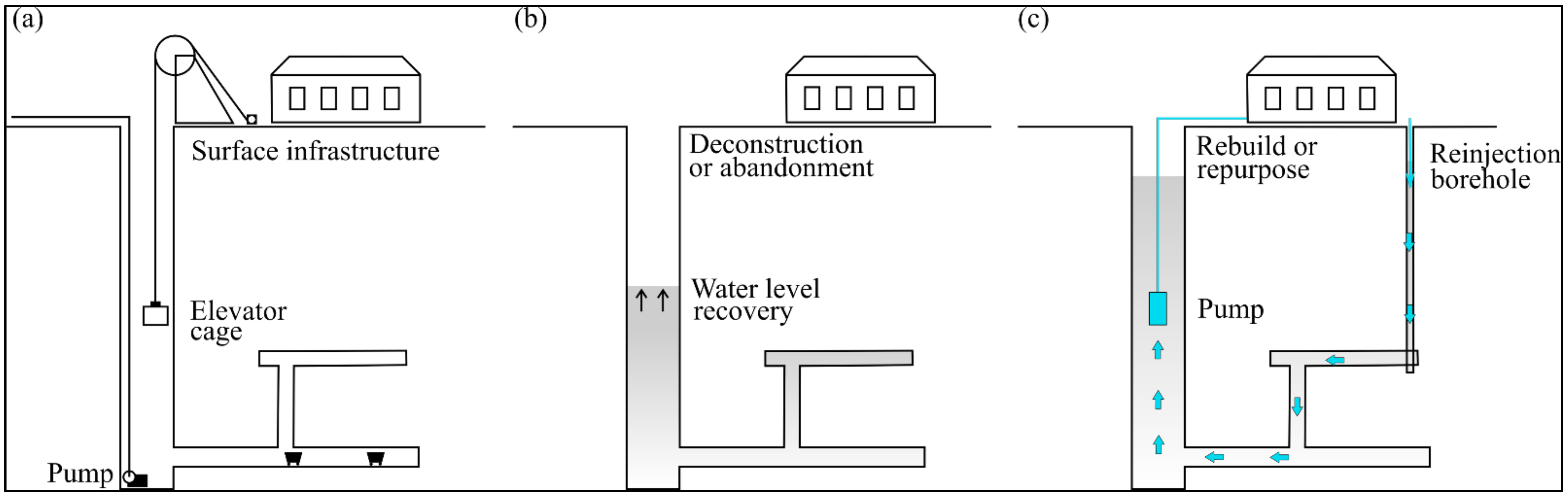
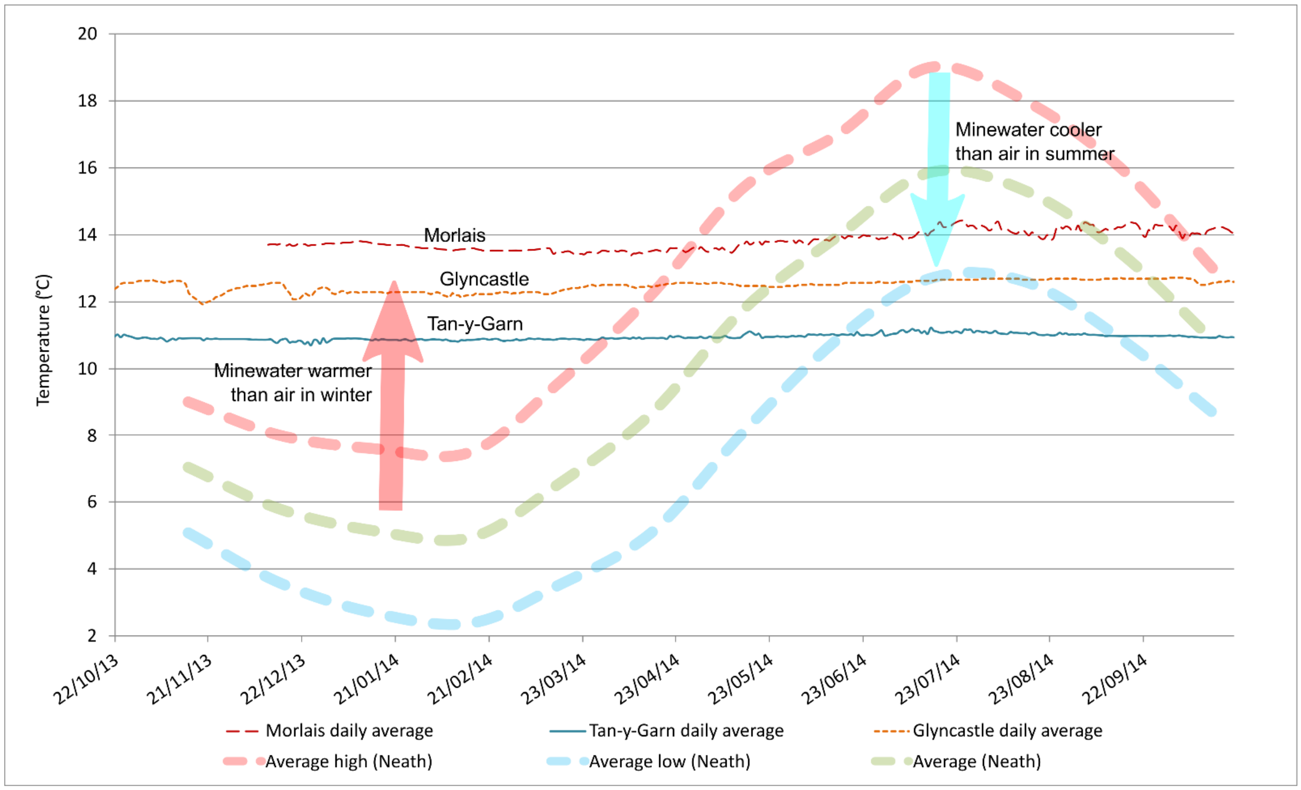
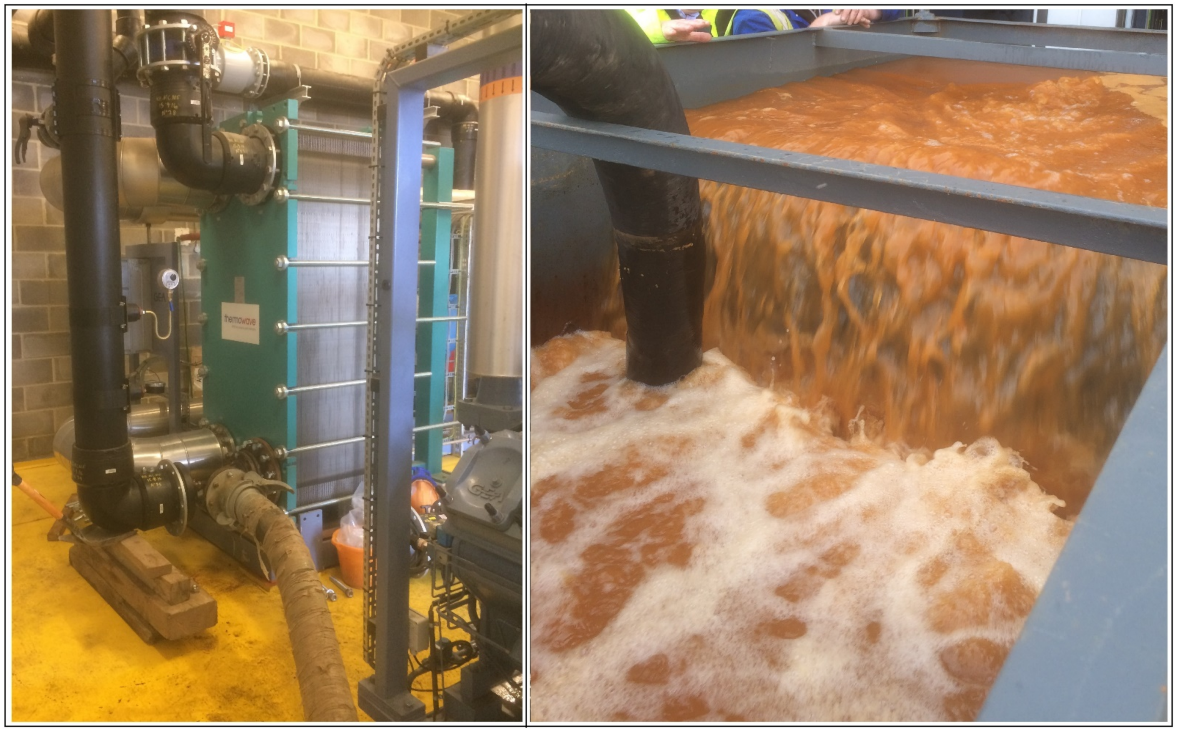
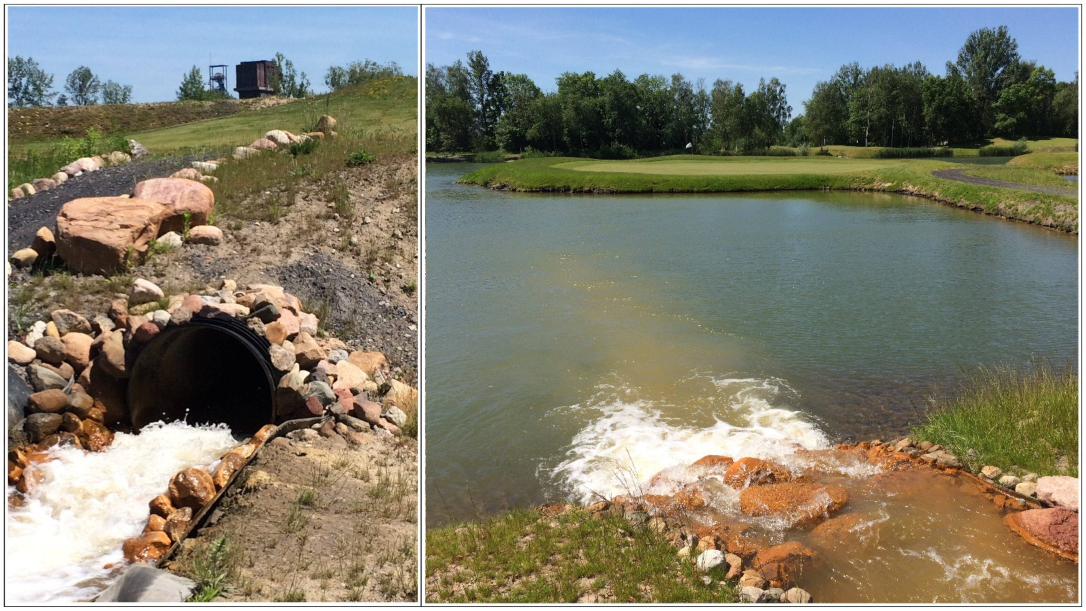
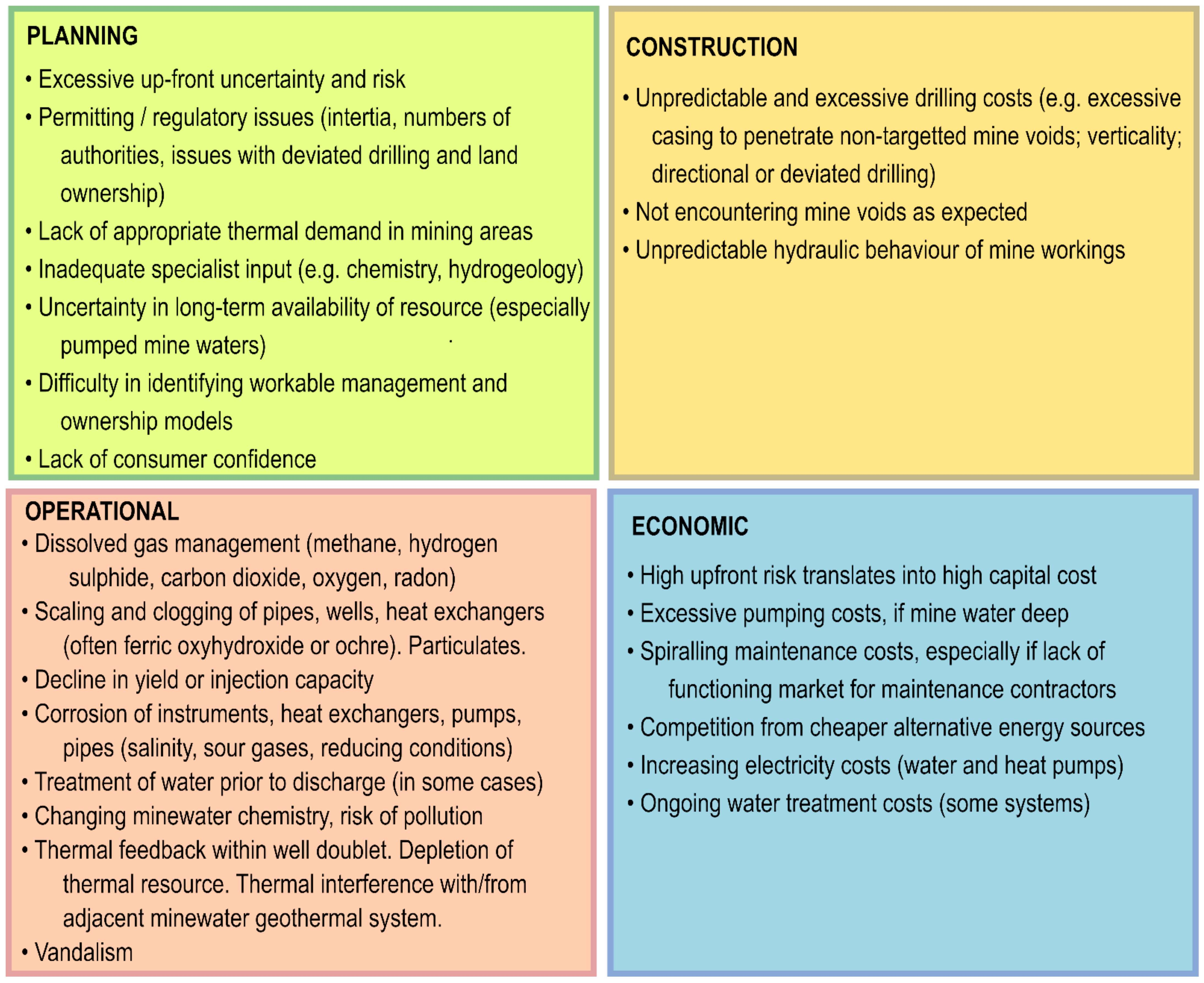
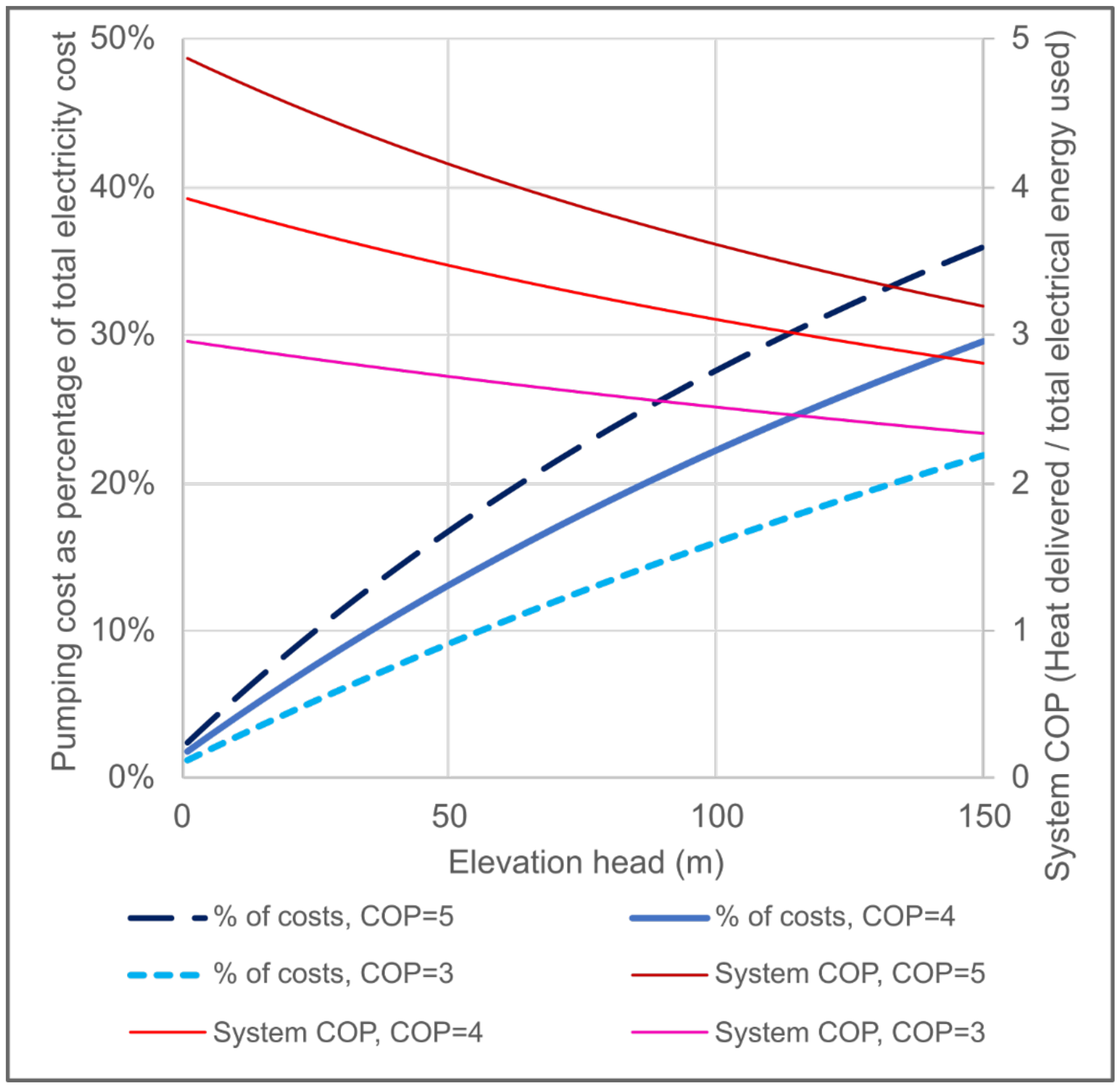
Table 1.
Minewater geothermal energy systems in the USA detailed by Korb (2012) [41].
Table 1.
Minewater geothermal energy systems in the USA detailed by Korb (2012) [41].
| Location | Recipient | Year |
|---|---|---|
| Scranton, Pennsylvania | Architecture Centre | 2010 |
| Carbondale, Pennsylvania | Cable Company Building | 1980s |
| Kingston, Pennsylvania | Community Recreation Centre | 1981 |
| Kingston, Pennsylvania | Hospital Building | 1980s |
| Pittsburgh, Pennsylvania | Church Building | 2008 |
| Kingston, Pennsylvania | Radio Studio | 1979 |
Table 2.
(Overleaf) Issues reportedly encountered at the described MWG schemes. X = major difficulty, ◊ = some difficulty, * potential difficulty, but resolved. Grey cells = no information. HEX = heat exchanger. Be aware that there is a correlation between difficulties reported and detail of reporting.
| Not Encountering Mine Voids as Expected | Unpredictable Hydraulic Behaviour of Mine Voids | Inadequate or Declining Yield or Injectivity | Dissolved Gas Issues | Clogging/Scaling of Pipes, Wells or HEX | Corrosion | Water Treatment Required | Thermal Feedback | Excessive Pumping Costs/Energy | Cumulative Maintenance Burden | Lack of Long Term Minewater Availability | |
|---|---|---|---|---|---|---|---|---|---|---|---|
| UK | |||||||||||
| Shettleston | ◊ | ◊ | X | ||||||||
| Lumphinnans | X | X | ◊ | ||||||||
| Markham | * | ◊ | |||||||||
| Caphouse closed loop | |||||||||||
| Caphouse pumped minewater | X | ||||||||||
| Dawdon pilot | * | ||||||||||
| Abbotsford Road | ◊ | X | ◊ | ||||||||
| Nest Road | ◊ | ◊ | ◊ | ||||||||
| Crynant | X | X | |||||||||
| Norway | |||||||||||
| Folldal | |||||||||||
| Kongsberg | |||||||||||
| Russia | |||||||||||
| Novoshakhtinsk | |||||||||||
| Spain | |||||||||||
| Mieres | ◊ | ||||||||||
| Netherlands | |||||||||||
| Heerlen | * | * | * | ||||||||
| Poland | |||||||||||
| Bytom | X | ||||||||||
| Czeladz | X | ||||||||||
| Sobieski | |||||||||||
| Czech Republic | |||||||||||
| Jeremenko, Ostrava | |||||||||||
| Svornost, Jachymov | |||||||||||
| Canada | |||||||||||
| Springhill | X | ◊ | ◊ | ||||||||
| USA | |||||||||||
| Architecture Centre | |||||||||||
| Cable Company Building | X | ||||||||||
| Community Recreation Centre | * | ||||||||||
| Hospital Building | |||||||||||
| Church Building | |||||||||||
| Radio Studio |
Publisher’s Note: MDPI stays neutral with regard to jurisdictional claims in published maps and institutional affiliations. |
© 2021 by the authors. Licensee MDPI, Basel, Switzerland. This article is an open access article distributed under the terms and conditions of the Creative Commons Attribution (CC BY) license (https://creativecommons.org/licenses/by/4.0/).
Share and Cite
MDPI and ACS Style
Walls, D.B.; Banks, D.; Boyce, A.J.; Burnside, N.M. A Review of the Performance of Minewater Heating and Cooling Systems. Energies 2021, 14, 6215. https://0-doi-org.brum.beds.ac.uk/10.3390/en14196215
AMA Style
Walls DB, Banks D, Boyce AJ, Burnside NM. A Review of the Performance of Minewater Heating and Cooling Systems. Energies. 2021; 14(19):6215. https://0-doi-org.brum.beds.ac.uk/10.3390/en14196215
Chicago/Turabian StyleWalls, David B., David Banks, Adrian J. Boyce, and Neil M. Burnside. 2021. "A Review of the Performance of Minewater Heating and Cooling Systems" Energies 14, no. 19: 6215. https://0-doi-org.brum.beds.ac.uk/10.3390/en14196215
Note that from the first issue of 2016, this journal uses article numbers instead of page numbers. See further details here.