Purpose in Thermodynamics


1
Department of Mechanical Engineering and Materials Science, Duke University, Durham, NC 27708-0300, USA
2
Institute for Energy Engineering, Technical University of Berlin, Marchstraβe 18, 10587 Berlin, Germany
*
Author to whom correspondence should be addressed.
Energies 2021, 14(2), 408; https://0-doi-org.brum.beds.ac.uk/10.3390/en14020408
Submission received: 2 December 2020
/
Revised: 8 January 2021
/
Accepted: 8 January 2021
/
Published: 13 January 2021
(This article belongs to the Special Issue The Concept of Entropy and Its Application in Thermal Engineering)
Abstract
:This is a review of the concepts of purpose, direction, and objective in the discipline of thermodynamics, which is a pillar of physics, natural sciences, life science, and engineering science. Reviewed is the relentless evolution of this discipline toward accounting for evolutionary design with direction, and for establishing the concept of purpose in methodologies of modeling, analysis, teaching, and design optimization. Evolution is change after change toward flow access, with direction in time, and purpose. Evolution does not have an ‘end’. In thermodynamics, purpose is already the defining feature of methods that have emerged to guide and facilitate the generation, distribution, and use of motive power, heating, and cooling: thermodynamic optimization, exergy-based methods (i.e., exergetic, exergoeconomic, and exergoenvironmental analysis), entropy generation minimization, extended exergy, environomics, thermoecology, finite time thermodynamics, pinch analysis, animal design, geophysical flow design, and constructal law. What distinguishes these approaches are the purpose and the performance evaluation used in each method.
Keywords:
Purpose; thermodynamics; evolution; direction; exergy; entropy generation; finite time; constructal law
1. Introduction
Thermodynamics began as a science of the motive power of fire. It emerged during the industrial revolution in the 1800s, one hundred years after many inventions of engines. Today, every thermodynamics treatise begins with the laws of thermodynamics (the first and the second) and continues with thick volumes of applications (graphs, tables, and formulas) that teach the reader how to use thermodynamics purposefully, to produce more power to improve human life, and to elucidate natural phenomena (bio and non- bio) that can be put to human use.
From the beginning, there was purpose in the thermodynamics doctrine, as in the title of the first book on the subject, “The Motive Power of Fire” (Sadi Carnot 1824). The generation of power from fire and other sources (natural, animal and human) happened because of designs with evident purpose: to move things against the steadfast opposition posed by the ambient. This is true about thermodynamics in all its domains of application, from animals (physiology, locomotion) to all the designs driven by the earth engine (atmosphere, hydrosphere, lithosphere, volcanos and hurricanes) [1,2,3,4,5,6,7,8,9,10,11,12,13,14,15].
In this review we trace the presence and use of purpose from the beginnings of the physics of power to the newer scientific methods that underpin the doctrine today. Because purpose is a common word with many interpretations, we start with its definitions from Webster’s dictionary: 1. Something one intends to get or do; intention; aim. 2. Resolution; determination. 3. The object for which something exists or is done. 4. End in view.
Purpose has been in thermodynamics all along, and it should become clear after reading this article. We believe that purpose in thermodynamics is a combination of all four meanings above, and that it is succinctly represented by the observation that the flow systems driven by power from fire have evolution, that is, flow configurations that change with freedom in a discernible direction in time [16,17]. Purpose is a unifying feature of all moving designs in nature, therefore purpose is associated with the thermodynamics of everything that moves and evolves.
2. Fire
Before the power from fire, there was the harnessing of fire. People learned to shape a fire (a pyre, from πυρά in ancient Greek) so that it looks like the profile of a Pyramid from Egypt. People do this unwittingly, yet this good habit has a purposeful origin [17,18,19]. When the height of the pyre is approximately the same as its width at the base, the fire is the hottest. By feeling warmth, prehistoric humans discovered the good effect of varying and choosing the fire shape. More recently, home dwellers discovered the good effect of the taller chimney that draws fresh air into the fireplace.
Today we know the physical reason for the common fire shape. When the pyre is too shallow (i.e., not tall enough) the fire does not draw a significant stream of fresh air into its burning volume, and consequently its volume is not the hottest. When the pyre is too tall and slender, its volume is cooled over its height by exposure to the surrounding colder air, and again its volume is not the hottest that it can be. The in-between shape at the intersection of shallow and tall asymptotes is the Pyramid shape of the hottest fire (Figure 1).
Chief in the evolution of the homo sapiens was the taming and use of fire 1.5 million years ago. This happened much earlier than harnessing the wind (boating, 150 thousand years ago), domesticated animals (10,000 years ago) and nature in general (as science, 2500 years ago). With fire, the effect of the effort of the naked human was enhanced greatly, with better food, longer lasting food, warmth, dry shelter, warding off animals and human enemies, and communicating from hilltops the approaching danger.
Fire is essential for the civilization and knowledge that we now have. Three centuries ago Newcomen and Watt figured out how to extract motion from fire. The motive power derived from fire represented the original scope of the science of thermodynamics, which is now an immutable pillar of physics and engineering.
The fire shape is an icon of ‘purpose’ in thermodynamics. The pyramid shape of the fire conveys two crucial messages to us:
- (i)
- With fire we have access to power.
- (ii)
- With the freedom to change the shape we have access to even more power.
It is not a coincidence that all the dry-stone pyramids of Egypt and Central America have the same shape. They are manifestations of the rewards from the freedom to change the design [(ii) above], because when the stone pyramid is shaped like its namesake (the pyre) the total human effort (the work) needed to move the stones horizontally and then stack them all up is reduced [19] (Figure 2). The rewards from the freedom to morph the flow architecture are physical. In thermodynamics, they are measurable in such terms as savings in the power (or food and fuel) needed to move things on the earth’s surface.
One reviewer commented that power comes not only from fire, but also from other sources, such as earth, sun or wind. Here is why in this section we highlighted the fire shape phenomenon:
Power comes from heating (heat transfer rate), and from power comes motion, movement, flow and change. This is the universal phenomenon of nature that is captured by thermodynamics (thermo + dynamics), as in the title of the first book that recognized this part of physics: ‘The Motive Power of Fire’, by Sadi Carnot.
Fire was harnessed the earliest in the evolution of the human and machine species [16,17], where “machine” means any contrivance, artifact, and add-on. The shape of the fire was highlighted because it is the earliest and simplest example of the design, optimization and performance of the effect of heating.
The other sources mentioned by the reviewer (earth, sun, wind) are covered by the universal phenomenon recognized above. Power comes from heating, and heating also comes from the sun, directly and indirectly. The winds and the mineral deposits in the earth (coal, oil) are (or were) driven by power from the sun as well, just like the waterfalls and the ocean currents.
3. More Power
The human urge to have access to more power continues today. The generation of power worldwide continues to increase (e.g., Figure 3) to cover the human needs. Rising are also the fuel consumption and the freedom to make changes in the physical features of the things set in motion by fire: heat currents, streams of working fluids, and bodies (pistons, turbine blades, shafts, vehicles). Here are just two examples that illustrate the universal trends that emerge in the evolution of designs that morph because of this freedom:
First is the monotonic increase in the highest efficiencies of the power plant types that have been adopted over the years (Figure 4). The multitude of engine designs is the domain (the population) of ‘the possible’. It is like a hill the crest of which is rising over time. At any point in time, above the hill lies the domain of the impossible designs, which also include the designs that do not serve the intended purpose (e.g., power generation with unacceptable cost or public safety).
Evolution is the name for the rising crest, or for why the size of the impossible realm is shrinking over time. Yet, because the second law efficiency (ηII, or exergetic efficiency) has to remain well below 1, the slope of the rising crest decreases with time while continuing to remain positive. This trend is known as diminishing returns, or as the maturing of a technology, in this case the power generation technology.
Second is the effect of size. Among plants using comparable technologies, bigger power plants are, in general, more efficient. Figure 5 shows this as another hill with a rising crest that separates the possible designs from the impossible designs. On the ordinate is the first-law efficiency (η), or the energy-conversion efficiency, and on the abscissa is the power of the engine, which in this case accounts for its size. Bigger plants using comparable technologies tend to be more efficient because the larger size allows for wider passages for fluid flow, and larger surfaces for heat transfer. In other words, the bigger size permits the design to operate with lower inefficiencies per unit of input and lower cost per unit of output, while the design evolves with freedom. This trend is the natural (physical) phenomenon known as economies of scale [20].
The upward trends in Figure 4 and Figure 5 continue because the flow configurations of contrivances (e.g., thermal power plants) have freedom to morph in the direction of more power delivered to the user (the mover) per unit of fuel consumed. This is illustrated with three frames from the historic development of gas turbine power plants, also known as Brayton cycle, Joule cycle, or air standard cycle engines.
From left to right in Figure 6 (top) we see how the configuration of the flow hardware has evolved toward more components, or greater complexity. To the original design with four components (heater, turbine, cooler, compressor) was added a regenerative heat exchanger, to improve the efficiency. Later, even more components became part of the design (multi-stage compression with intercooling and expansion with reheating) to increase the power generated per unit mass of the working fluid. In the same direction of evolutionary design, the efficiency of power plants increased because the thermodynamic average temperature during heat supply (TH,avg) increased, while the thermodynamic average temperature (TL,avg) during heat removal from the overall system decreased.
These steps are shown on T-s diagrams in Figure 6 (bottom), and they correspond to the three configurations shown in Figure 6 (top). From left to right, more features (dimensions) that can be varied in each design, and there is no guarantee that the rightmost design is more efficient than the middle one. This possibility is the essence of the thickness of the mountain of ‘the possible’ sketched in Figure 4. Yet, the left-to-right sequence of Figure 6 is about the slope of the mountain crest in Figure 4. Step by step, the ratio (TH,avg/TL,avg) increased, and the string of designs evolved toward possible designs with higher efficiencies. Evolutionary design sequences similar to Figure 4, Figure 5 and Figure 6 have been illustrated for refrigeration plants as well [21].
One reviewer asked us to clarify how the demand for more power is related to the “purpose in thermodynamics”, why only the evolution of gas turbine power plants as an example (Figure 6), and why we use “power” instead of “work” or “heat.”
According to the constructal law, the tendency of any flow configuration that evolves freely is to change toward configurations that provide easier access to what flows. The time direction of the evolving configuration is the concept of “purpose” most generally, as physics.
In the human sphere, this means evolution toward more and easier movement for humans and their kin and belongings. The sequential adoption of fire, boating, domesticated animals, agriculture, windmills, water wheels, steam engines, science, etc., proves the reality of “purpose,” and the validity of the preceding paragraph.
We exhibited only the evolution of gas turbine power plants because of space limitations, and because the montage made in Figure 6 is new, original. We indicated that the evolution of other power systems is available pictorially in the literature, for example, for refrigeration plants [21].
We use “power” not “work” of “heat” because the motion driven by power is happening in time. The movement is the phenomenon (the observed image), and it is happening in time. Power is work transfer in time, per unit time. By the way, this is one more reason why we highlighted “fire”, because fire is the observation (the icon) of heating in progress. Heating and power (both measured in watts) say a lot more about nature than a number of joules of work or heat.
4. Methods
More recently, the evolutionary direction indicated by Figure 1, Figure 2, Figure 3, Figure 4, Figure 5 and Figure 6 was accompanied by the development of scientific methods for the analysis and design of flow systems that deliver more power per unit of fuel use, and more cooling (refrigeration, liquefaction) per unit of power used.
The first and broadest method is thermodynamic analysis. As shown in Figure 7, by invoking the first and the second laws of thermodynamics (i.e., by applying energy and entropy balances) for the thermodynamic system under consideration (the blue disc in Figure 7) we can determine the maximum work output per unit of fuel used, or the power output derived from the consumption of fuel at a certain rate. This descriptive method indicates the relationship that exists between the inflows and the outflows (mass, heat, work) that cross the boundary of the system.
The first and second laws of thermodynamics do not command the configuration of the system to evolve over time such that it generates more power. This is a key observation because with modern methods such as exergy analysis and entropy generation analysis one can discern what changes can be made in the system configuration to obtain more from the system. Note that to decide to change the system that serves us is not commanded by either the first law or the second law. This is because the two laws refer to “any” system, which is a black box without a specified configuration. The first and second laws say nothing about configuration, time, and evolution of configuration.
The birth of configuration and the time direction of its evolution become apparent if we consider the question at the top of Figure 8. The produced power is dissipated while the user (the body driven by the power) moves to a distance, against the opposition posed by the environment. The word “weight” (not mass) in Figure 8 is correct. On earth, every moving body has weight, which is the force equal to the body mass (m) times the gravitational acceleration (g). The weight is oriented vertically, perpendicularly to the movement that is (on average) horizontal. The force overcome by the mover is horizontal, and it is proportional to the weight, in all media, water, land and air [11,12,13,14,15,16,17].
Nature is represented incompletely by the power producers sketched inside the system of Figure 7. Part of nature is also the environment situated close to the system (the niche), which acts as a brake against the movement driven by the produced power. This is shown in Figure 8.
Nature consists of engine & brake systems, which are everywhere, in all the realms (bio, non-bio, geo, socio, human-made and not-human-made systems). Natural convection phenomena are extremely common examples of engine & brake systems at all scales, in the atmosphere and the hydrosphere. The evolution of any flow configuration that has freedom to morph is accounted for by an additional first principle, the constructal law [1,2], Figure 9. Thermodynamics now accounts for phenomena of configuration and evolution, in addition to the phenomena that before 1851 were covered separately by mechanics theory and caloric theory. During the past two decades the use of the constructal law spread, and its predictive power cleared up puzzles that were persisting in science. Nine examples of such progress, bio and non-bio, are offered by the tableau shown in Figure 10. The nine applications of constructal theories that predict these evolutionary designs are available for river basins, cracks in drying mud, turbulence, lung architecture, blood capillaries, underground rivers and shafts of volcanos, droplet splat versus splash, and all animal locomotion [16,17,20,21].
How the thermodynamics discipline reached this stage, to account for the time direction of design change (evolution, Figure 9), had a lot to do with the energy crisis of 1974, which caused a reawakening to the importance of thermodynamics and its fundamentals. Highlights of the developments that were to follow were already in the proceedings to the 1979 world gathering in Washington [22]. The methods of design and performance increase are outlined below in terms of the textbooks and literature reviews that appeared, and which could be consulted for further study. This literature is reviewed next. The methods appear to be diverse with regard to objectives (measures of performance or values used to decide about improvement: efficiency, costs, rate of return, payback time, environmental impact, maximize versus minimize), yet they represent the same idea: there is a direction to design change, and it is good for performance.
4.1. Exergy Analysis (EA)
Exergy analysis (EA), or exergetic analysis [23,24,25,26,27,28,29,30,31], identifies the location, magnitude and causes of inefficiencies in the thermodynamic system that has the purpose of delivering one or more useful streams to the environment (the user), e.g., power, heating, cooling. The inefficiencies are measured in terms of exergy destruction, or exergy loss. Based on the information obtained by an exergetic analysis, changes in the design and operation of a system can be identified to improve its thermodynamic efficiency [23,28,29].
An exergy analysis can be applied to any system, independently of its complexity, and represents the most effective method for evaluating and improving thermodynamic efficiency, particularly in complex systems. As demonstrated in Refs. [32,33], an exergy analysis can stimulate and guide creativity by assisting in the development of completely new energy conversion concepts.
In brief, exergy analysis consists of invoking simultaneously the first law and the second law in the analysis of a process executed by an unambiguously defined thermodynamic system. For example, if the system is open then its change per unit time is described by the first law, second law, and mass conservation, this way:
The notation is classical, cf., Nomenclature. Noteworthy are the instantaneous extensive properties of the system [E(t), S(t), M(t)], the work input per unit time (), and the heat transfer inputs received from (n + 1) temperature reservoirs (Ti). Special among the reservoirs is the ambient (T0, P0), or i = 0, where P0 is the ambient pressure, and is the heat transfer rate through a boundary of temperature T0.
With statements (1)–(3), thermodynamics is complete. What follows are rewritings of those principles in special notations made necessary by analyzing systems with purpose. To start, the entire left side of the inequality (2) is called entropy generation rate.
Next, by eliminating between Equations (1) and (2), we obtain the work transfer rate delivered by the system
Available to the user (who is part of the environment) is minus the work done by the system to displace the environment, P0dV/dt, where V (t) is the system volume:
The left side is the rate of exergy (useful energy) output,
The various terms on the right side of Equation (6) indicate the extent to which the changes in the properties of the system contribute to the exergy output, in this order: the decrease in the non-flow exergy inventory (E + P0V − T0S), the exergy transfer associated with heat transfer from the temperature reservoirs other than the ambient , and the net inflow of flow exergy .
Entirely new concepts and terminology arise when we compare Equations (1)–(7) with their version in the limit of reversible operation namely , etc. The rate of exergy output is (from Equation (6) with ), and the difference between and is the rate of exergy destruction (or, lost power, ) due to irreversible operation,
Exergy destruction, and what to do about minimizing it, is not to be confused with the exergy analysis that ended with Equation (7). Exergy analysis relies solely on the laws of classical thermodynamics. Next, the changes in configuration aimed at reducing exergy destruction to increase are an entirely different concept (purpose), on which we focus in the remaining sections.
Purpose and value are central in exergy analysis, where a product is defined unambiguously [23,34] for every system component and process according to its purpose, and where exergy represents the thermodynamic value of a carrier of energy. An exergy analysis provides the most rigorous definitions of thermodynamic efficiency and also the foundation for assigning costs and environmental impacts to energy carriers. Furthermore, an advanced exergy analysis [35,36,37,38] assesses (a) the part of the exergy destruction that realistically could be avoided in each component or process, and (b) the interactions among the exergy destructions within the different components or processes. In this way we obtain the most complete thermodynamic analysis possible based on the first and second laws, and very useful information on the required changes in the overall system to improve its thermodynamic efficiency. EA forms the basis of the exergy-based methods that include the exergetic, exergoeconomic (Section 4.5), and exergoenvironmental (Section 4.6) analyses, which form a consistent set of powerful analyses from the viewpoints of thermodynamics, economics and ecology.
4.2. Entropy Generation Minimization (EGM)
Entropy generation minimization (EGM), or irreversibility minimization, is closely related to exergy analysis, and was developed during the same period [39,40,41,42,43,44,45,46,47,48,49,50,51,52,53,54,55,56]. The relation between the two methods rests in the Gouy-Stodola theorem [23],
which follows from Equation (8), or from invoking the first law and the second law simultaneously [21]. This theorem states that the amount or rate of exergy destroyed irreversibly within a thermodynamic system or component is equal to the entropy generated in the same system or component times the temperature of the environment. There is only one purpose in EGM (the same as after EA), namely to bring the system to operate closer to the reversible (ideal) limit.
The methods of EA and EGM have many similarities, and they both reveal the thermodynamic imperfections in the system. This is not sufficient: the next step should be to discover how to change the system so that the improvement is possible and can be implemented [46]. The EGM concept deals only with the real thermodynamic inefficiencies within the considered system, and, unlike EA, it does not contribute to the definition of a general rational efficiency for components and processes based on the second law, or permit the assignment of monetary values and environmental impacts to energy carriers and to the inefficiencies. The concepts of size and material constraints are present in both methods [57]. The EGM method can account for the thermodynamic losses (irreversibility) associated with transport between system and environment, as in the optimization of rhythmic storage of sensible and latent heat [21], but does not consider the exergy losses associated with the transport of material to the environment.
4.3. Cumulative Exergy Consumption (CEC)
Cumulative exergy consumption (CEC) considers all thermodynamic inefficiencies that occur in the entire chain between the point where all natural resources used in the process are obtained from the natural environment to the point where the final product is generated [58,59,60,61,62,63,64]. This approach extends the system boundaries of the thermodynamic analysis to include all processes that previously were used to provide the feeds to the process under investigation. CEC accounts for how the inefficiencies of this process affect the inefficiencies of the processes that provide the feeds, and vice versa. This information is used in calculating some environmental impacts associated with the process that is being considered (see Section 4.6).
4.4. Extended Exergy Analysis
Extended exergy analysis is also based on the calculation of the cumulative exergy consumption, but takes into consideration additional aspects such as the exergy associated with capital (investment costs) and human activity (labor) [60,65]. The extended cumulative exergy consumption associated with the investigated system is minimized. The conversion of monetary values (e.g., capital investment and salaries) and environmental impact into exergy values is rather arbitrary and reduces the usefulness of the method for practical applications.
4.5. Cost Minimization
Cost minimization in the design of an energy system means finding the appropriate trade-offs between (i) the contributions of investment cost, and (ii) the sum of fuel cost and other operating and maintenance costs. This is done by considering the entire lifetime of the system. For an existing system, the contribution of investment cost is not considered in the cost minimization because it represents a sunk cost. In the mathematical cost minimization [66,67,68,69,70] of the design of a non-existing energy system, decisions need to be made about the thermodynamic variables. Therefore, we need to know the investment costs of components as functions of thermodynamic variables: such information is not readily available. In addition, we need to include in the optimization considerations related to safety, maintainability, and operability of the plant. These, however, cannot be readily included in a mathematical model.
An alternative to the mathematical optimization techniques are the iterative exergoeconomic methods [23,25,30,34,63,71,72,73,74,75,76] that use the principle of exergy costing. Exergoeconomics is a unique combination of exergy analysis with economic analysis. In this combination exergy serves as the only rational basis for assigning monetary values (costs) to energy carriers and to the thermodynamic inefficiencies (exergy destruction) within a system. The exergoeconomic model of an energy conversion system consists of cost balances and auxiliary equations associated with costs per unit of exergy. Exergoeconomics identifies and evaluates the real cost sources. The cost of exergy destruction in each component is calculated and compared with the contribution of the corresponding investment cost. By applying these methods iteratively, one can include in the optimization additional factors referring to safety, maintainability, and reliability, which cannot be considered in a mathematical optimization technique. Key sources in exergoeconomics are Refs. [23,30,34,63,72,77,78,79].
The terms thermoeconomics and exergoeconomics were used in the past as synonyms. Today there is a growing need to distinguish the methods (exergoeconomics) that apply the principle of exergy costing [34,63,78,79] from those that do not apply this principle in combining a thermodynamic analysis with an economic analysis (thermoeconomics), and cannot provide the wealth of information supplied by the exergoeconomic methods for system improvement.
In an advanced exergoeconomic analysis [35,36,38,76,79,80,81,82,83,84,85,86,87], both the exergy destruction as well as the costs associated with investment and exergy destruction for each system component are split into unavoidable and avoidable, and endogenous and exogenous terms. By focusing in the analysis on the avoidable endogenous and avoidable exogenous exergy destructions and costs, designers obtain the best possible information from today’s perspective for system improvement.
The exergetic cost [30] is expressed in exergy units and is calculated when in an exergoeconomic analysis all investment costs and all operation and maintenance expenditures are neglected, and the fuel cost per unit of exergy is set equal to one. The concept of exergetic cost provides the user with the exergy amount required to generate every stream within the system. This concept can be used for apportioning energetic resources among the different product streams generated by the same system.
4.6. Minimization of Environmental Impact
Minimization of environmental impact is the object of environomics, thermoecology, and exergoenvironmental analysis [78,88,89,90,91,92,93,94,95,96,97,98,99,100,101,102]. When only one pollutant is considered, the minimization of the emission of this pollutant is a simple task. When more than one pollutant must be considered simultaneously in a system (e.g., CO2, CO, NOx, SO2, and solid particles), the question arises how to compare 1 kg of one pollutant with 1 kg of another. A common currency is needed, and in the methods discussed below, this is found in monetary values (environomics), in exergetic terms (thermoecology), or in a composite environmental index (Eco-indicator) in the exergoenvironmental analysis.
In environomics [89,90], monetary values (costs) are assigned to the environmental impact associated with each pollutant. Then the exergoeconomic model (Section 4.5) is extended to include the costs of pollutants, and a cost minimization problem is solved. The assignment of costs to environmental impacts in this way is more or less arbitrary, and represents a significant weakness of environomics.
In thermoecology [78,88] the depletion of non-renewable natural resources and the effects of pollutants are expressed in exergy terms. The resulting thermoecological cost (also expressed in exergy units) is based on the cumulative consumption (Section 4.3) of non-renewable exergy, and includes the cost associated with the rejection of harmful substances to the natural environment.
In an exergoenvironmental analysis [38,79,83,91,92,93,94,95], a one-dimensional characterization indicator is obtained using a life cycle assessment (LCA). This indicator is used in the exergoenvironmental analysis in a similar way as the cost is used in exergoeconomics. An index (a single number) describes the overall environmental impact associated with each exergy carrier and the manufacturing of each system component. The Eco-indicator 99 [103] is an example of such an index. The exergoenvironmental model of an energy conversion system consists of balances and auxiliary equations associated with environmental impact. One difference between balances written for an exergoeconomic and for an exergoenvironmental analysis is that in the latter additional terms are used to account for the pollutants generated (or consumed) through a chemical reaction within a component or process of the overall system. An exergoenvironmental analysis identifies and evaluates the real sources of environmental impact, and calculates the impact associated with the exergy destruction within each component.
In an advanced exergoenvironmental analysis [38,96,97,98], both the exergy destruction and the environmental impact associated with exergy destruction and construction or manufacturing associated with each system component are split into unavoidable and avoidable terms (on one side) and endogenous and exogenous terms (on the other side). By focusing on the avoidable endogenous and avoidable exogenous exergy destructions and environmental impacts, designers obtain the best possible information from today’s perspective for system improvement from the ecological viewpoint. It should be emphasized that the evaluation of environmental impacts will always be subjective and limited because of some uncertainties. However, the information extracted from an exergoenvironmental analysis is always useful for reducing the environmental impact of energy systems.
4.7. Pinch Analysis
Pinch analysis is applied to heat exchanger networks (HEN) to identify their thermodynamically optimal configuration [23,99,101,104]. HEN are the only thermodynamic systems in which an exergy analysis could provide inferior results compared to a pinch analysis. In this sense, a pinch analysis complements an exergy analysis. Attempts to extend the principles of pinch analysis to systems other than HEN were not as successful as an exergy analysis. Pinch analysis received a wider acceptance than exergy analysis because the pinch analysis is applied as a ‘recipe’, whereas the more general exergy analysis requires some experience and some creative thinking from the users.
4.8. Finite Time Thermodynamics (FTT)
Finite time thermodynamics (FTT) is a relatively recent name [105] given to a simple method of system modeling that began spreading in thermodynamics in the 1950s and 1960s [106,107,108,109,110,111]. The advances that preceded the FTT name were reviewed in [112]. The essence of the method is graphic and purpose driven. It consists of approximating the thermodynamic system (e.g., power plant, refrigeration plant) as an assembly of building blocks of two kinds: blocks that function irreversibly, with entropy generation, and the rest of the system, which is proclaimed to function reversibly. The irreversible parts are also named external, and the rest (the reversible) is named internal, from which the alternate name “endoreversible thermodynamics” for this method. This modeling activity was presented for the first time in textbook form in 1982 [39] (see also the commentary [112]), and next in 1988 in the first edition of Ref. [21].
The ‘finite time’ emphasizes that the thermodynamic system is subjected to finiteness constraints. The finite size of its components fits hand in glove with the finite time that its flows have in order to occur. The bottom line is that finiteness of size and time prevents flows from occurring reversibly, i.e., driven by zero gradients of pressure, temperature and concentration. The finite-time literature, unfortunately, continues with papers that repeat a modeling error made originally in 1975 [111], before the finite-time name was coined. The model was that of a heat engine that operates at ‘maximum power’ while in contact with two heat ‘reservoirs’, one hot and the other cold. The model was flawed because it relies on the false assumption that there exist two heat reservoirs that drive a heat engine. This assumption is false because ‘engine’ is a human add-on (contrivance, artifact, machine) the purpose of which is to enhance the effect of human effort. Specifically, a heat engine has such an effect because:
- It generates power because it receives a heat current from its environment.
- Heat input comes from a fuel (a part of the environment) that is burned at a finite (expensive) rate; the fuel is hard to come by, it is eminently not a ‘reservoir’.
- Even in a heat engine driven by solar heating (on earth, or in outer space), the heating rate is finite because it is dictated by the size of the collector, which is finite and expensive (land area, materials, construction costs, mass launched in orbit).
- On earth, where people with their ‘heat engines’ and science live, there is only one heat reservoir: the ambient (atmosphere, hydrosphere, T0).
The mistake is the view that the rate of heating that the engine receives is free to vary, i.e., it is a degree of freedom of the system. This point needs explaining, because it is true that when one improves the system (by changing the internal configuration) other changes occur, such as the heat flow rates to some components [46]. The point is that the original 1975 proposal [111] was about the whole power plant, not about heat transfer rates to some internal components that change configuration. Said another way, the internal heat transfer rates come from burning a steam of fuel at a certain rate. One may vary that fuel rate (say, to accelerate a vehicle), but “fuel” is not an infinite reservoir. It is not like the ambient (atmosphere, hydrosphere).
An additional weakness of FTT is associated with the very rudimentary models used in system simulations that have little to do with reality. An example is the assumption that a part of the engine operates reversibly. These features were exposed by several thermodynamicists [113,114,115], and they have become teaching material in textbooks and reviews of thermodynamics [21].
Important is the idea that permeates through the FTT papers is that the thermodynamic system exists with purpose, even though ‘purpose’ is not acknowledged directly. The concept of purpose is presented in terms such as maximum power, minimum entropy generation (EGM), finite size, finite time, performance, and other words less common than purpose.
4.9. Constructal Law
Constructal law was formulated in 1996 to account for purpose and directionality, and to define life, evolution and time in physical terms: “For a finite-size flow system to persist in time, it must evolve with freedom such that it provides greater and easier access to its flows”. The field that developed around the constructal law is being reviewed regularly in physics, biology and engineering journals and books [116,117,118,119,120,121,122,123,124,125,126,127,128]. This work is predictive, and it offers principles of evolution for animal design, geophysical design, social design, and science and technology.
For example, the constructal theory of locomotion [11,17] (animals and vehicles on land, in water and in the air) predicted correctly that the work (W) required by a body to move over a distance (L) on earth has the universal scale W ~ rmgL, in which the factor r accounts for the medium in which the movement occurs (namely, r ~ 1 in water, r ~ 0.1 in the air, and 0.1 < r < 1 on land). This W scale is correct even though mg is vertical and L is horizontal: The W scale is correct because the product rmg accounts for the horizontal force overcome by the body as it displaces the medium during its movement over L. To have locomotion of animals on earth, weight must be lifted, as is evident in fliers, runners and swimmers.
Constructal law, theory and design continues to offer a wealth of new mental images and drawings of how flow configurations should occur and evolve in nature. This began in 1996 with the publishing of high-access paths for urban flow [129], heat conduction [130], and fluid channel flow [131]. In 1998 was published the erosive evolution of tree channels in a fluid-saturated porous medium with Darcy flow: Figure 11 shows the evolution of a river drainage basin under uniform rain that dislodges grains from the square area [132].
In time, the flow carves its own river basin, and as a consequence the whole area flows more easily. In three dimensions, the same evolutionary design consists of one tree flow matched to another tree flow, or the modular flow architecture that bathes a volume with one stream that enters from one point and exits from another point (Figure 12) [133,134]. Additional drawings and applications are discussed in Refs. [135,136,137,138,139,140,141,142,143].
One reviewer commented that in this section several thermodynamics methods are reviewed, but the differences and applications of these methods are not provided. He or she also noted that these methods could be applied in “engineering thermodynamics”, but would not be very suitable in "chemical thermodynamics” and other domains.
In Section 4.1, Section 4.2, Section 4.3, Section 4.4, Section 4.5, Section 4.6, Section 4.7, Section 4.8 and Section 4.9 we described no less than nine methods by indicating what was special about each method. This means that we indicated the differences between methods, again, subject to severe space limitations. Because of space limitations we did not use equations to describe all the methods: the equations are available in the literature cited for each method. The present article is a review, not a handbook. In some cases that are not as well-known as others, we relied on graphics, such as Figure 11 and Figure 12.
The methods that we reviewed above have general applicability. The examples tend to come from engineering because this is the domain that documents most readily the “purpose” that guides any evolutionary flow design. Yet, the field of applications is much broader: the subject of “fire” is the chemical thermodynamics (combustion), the drainage basin (Figure 11) is the earth thermodynamics, and the vascular design (Figure 12) is the animal design. This broad applicability is how our review began (cf, references [1,2,3,4,5,6,7,8,9,10,11,12,13,14,15,16]), and note that “purpose” is very much a topic in biology today.
5. Remarks
The methods reviewed above recognize in ad-hoc manner the presence of evolutionary direction, or purpose in the systems analyzed with thermodynamics. The purpose of the doctrine that grew from the steam engine and Sadi Carnot’s idea was to identify the first principles of the transformation of heating into motive power and vice versa, and how to configure the systems that offer (or provide) more efficiently the transformation. The first principles became thermodynamics, while the purposeful changes in configuration remained to be recognized and included.
The first law is a brief summary of observations of phenomena of energy conservation. The second law is a brief summary of observations of phenomena of irreversibility, or one-way flow. The evolution of flow configuration in a discernible direction in nature is another phenomenon, which is distinct from the phenomena accounted for by the first and second laws.
In sum, the methods of Section 4.1, Section 4.2, Section 4.3, Section 4.4, Section 4.5, Section 4.6, Section 4.7, Section 4.8 and Section 4.9 recount the struggle to account for direction, and purpose, and to develop the scientific language in which the new law and its new phenomenon are added to thermodynamics (Figure 9). They illustrate what has been missing in thermodynamics from its beginnings two hundred years ago. Missing was a first principle that accounts for the physics of evolution of configuration in a time direction that is identifiable as change after change.
Although purpose was not recognized in thermodynamics until the methods reviewed in this paper began to emerge, purpose was commonly present in the words and drawings that formed the discipline. This is why it is fitting to conclude this review with a look at the meaning of the messages conveyed by our words and drawings.
Key is the word ‘process’, which means the change in the state of the system. Often the change occurs because of movement, as in the case of a piston moving inside a cylinder and compressing an amount of gas, which is the system. The image (the state) changes, but the system remains. Image change, or evolving design, does not mean system change.
The configuration that changes is said to evolve. The word ‘evolution’ has the direction of time in it. Its origin is the Latin verb evolvo, evolvĕre, which means to roll out, to roll forth. It conveys the image of birth and nature (in Latin, Natura is she who gives birth to everything). The direction in the word evolution is clear. Here are a few more key words the meaning of which deserves to be refreshed for use of thermodynamics in the future:
Phenomenon is the one name given to numerous observations of the same kind that occur in nature, everywhere. For example, one phenomenon is ‘irreversibility’, which is the natural tendency of any flow to proceed (by itself) one way, from ‘high’ to ‘low’. Another example is the conservation of energy, originally recognized in mechanics as the interconvertibility of the kinetic energy of a body into its potential energy.
Law is a brief statement (text, not mathematical equation) that accounts for the distinct phenomenon. For example, the law of the irreversibility phenomenon is the second law of thermodynamics. The law of the energy conservation phenomenon is the first law of thermodynamics. The law of the evolution of configuration phenomenon is the constructal law. Each law is a first principle because it cannot be deduced from other first principles.
Optimization means to make choices, to choose, for example, between configuration A and configuration B, or between flowing to the right or to the left. To opt comes from the Latin verb opto, optare, which means to choose. Strictly speaking optimization does not mean to model a system in nature, to express the model in terms of analytical functions, and to solve the equations that result from setting the first derivatives of those functions equal to zero [139].
Model is a much-simplified facsimile of the configuration of an object observed in nature. Modeling is observation, which means empiricism, not theory. The mathematical description of the model is empiricism.
Design means a drawing, a sign, a configuration that conveys a message, or a directive given to the viewer. Design comes from the words disegno (Italian) and dessin (French), which mean a drawing. Both originate from the Latin noun signum, which means a sign. Design, the noun, does not mean and should not be confused with the verb “to design”.
We express our mental image in terms of drawings—sketches, blueprints, computer graphics and numerical tables of dimensions and instructions (software) of how the computer should make the drawings. For example, the drawing of a river basin serves as map in geography, and its message is useful to all who view the drawing. The drawing of a human lung tells the surgeon where to make the incision. The drawing of a snowflake is also useful because it inspires the human mind to question and discover the single idea that accounts for drawings that look the same—river basin, lung, snowflake, and many more.
Design change, with which thermodynamics serves as a pillar for physics, is about the perceived genesis of design and evolution in nature. It is about morphing (dynamic) systems, not static systems. It is about macroscopic systems, not infinitesimal systems. It is about scientific inquiry oriented against reductionism. Above all, it is about images that occur in the human mind and lead to questioning the nature that is around us and inside us.
The physics of evolution has taken shape on the route traced in thermodynamics by new methods and principles (Figure 9). This new science provides the basis of phenomena and concepts that traditionally are not encountered in physics: evolution, design, freedom to change, life, performance, economies of scale, diminishing returns, innovation and social organization.
In thermodynamics we have ample opportunity to make drawings on the blackboard and in scientific writings. Here we illustrate this with six examples, each accompanied by two references, the original publication of the drawing, and the most recent comment on how that drawing reappeared as ‘new’ in the literature.
Figure 13 shows the heatlines in laminar flow, near the entrance to the duct [137,144]. These are the lines of how energy is convected downstream by the flow. To see them one needs imagination, which is subtle (harder to see) than visualizing and observing streamlines of fluid flow. To show streamlines to other observers, one can sprinkle sawdust on the surface of channel flow and record the movement of the debris. Heatlines, like heat and heat transfer, are purely mental viewings. One cannot photograph heat.
Thermal sciences came from the mental viewings, not from taking pictures. Heat transfer, as a stream with its own arrow, is the mental image behind the temperature-heat transfer (T-Q) diagram (Figure 14), which was first published in 1977 [49,145] and 1982 [39].
Heat exchangers are thought to facilitate the thermal contact between mating streams (Figure 15) [39], that is to enhance the heat transfer perpendicular to the direction of fluid flow. Subtle is that heat exchangers have the purpose to provide thermal separation in the end-to-end direction. Any heat exchanger leaks a stream of energy in the longitudinal direction, from the hot end of the two-stream assembly to the cold end. Thermal contact enhancement in the stream-to-stream direction is synonymous with thermal insulation in the longitudinal direction [39,146].
Power and refrigeration systems are considerably more complicated because they contain several heat exchangers, valves and work-transfer components (turbines, pumps, compressors). How the components contribute to the thermodynamic performance of the whole assembly can be visualized by the flow of exergy within the system (Grassmann diagram [147]), or by the distribution of entropy generation along the flow through each component, and along the system.
One power system assembly is illustrated in Figure 16 [21,148]. There are three heat exchangers in a Brayton cycle power plant (see Figure 6 top row, middle). Every heat exchanger functions imperfectly, which means that each generates entropy at the rate indicated on the ordinate. Increasing to the right on the abscissa is the effectiveness, which increases monotonically with the physical size of the heat exchangers.
Most interesting is the behavior of the ‘meat’ in the sandwich, the irreversibility of the regenerative heat exchanger, which shows a bulge at an intermediate size on the abscissa. This intermediate feature is misrepresented intentionally by the authors identified in Ref. [148], who are pushing the false notion of ‘entransy’ (reviewed in detail in Refs [2,3,4]), even though this feature has been corrected in the third edition of Ref. [21]. This feature does not take anything away from the expected monotonic (downward) trend of all the curves in Figure 14.
6. Conclusions
In this article, we reviewed the place of evolution and purpose in thermodynamics, and in physics in general. While conducting the review we encountered the need to clarify for the readers the physics and the meaning of the concepts that underpin “purpose.” Specifically, we defined phenomenon, law, optimization, model, and design. This effort benefits greatly from visualization, which is the art of instilling images in the mind—mental images that cannot be observed in physical objects.
For example, heating cannot be observed and photographed, but it can be visualized if one learns the method of drawing heatlines (Figure 13). The conversion of heating into power (the essence of any thermodynamics treatise) can be imagined in one view (Figure 14). The detrimental leakage of heat along a counter flow (e.g., blood flow in the leg of a wading bird) can be imagined in one view (Figure 15). Irreversibility is like heating and power: it cannot be observed, but it can be imagined in one view such as Figure 16.
In the human realm, “purpose” is why concepts are being clarified, and the impossible to observe is being visualized with creative methods. The train of clarification and creativity is the evolution of science itself, which is purposeful and unstoppable.
What about the future? Useful ideas will continue to spread naturally, in many ways, through creative writing, teaching, and many kinds of plagiarism [149] and willful misrepresentation. Purpose is the reason why the future of thermodynamics looks bright. Because thermodynamics now teaches exergy-based methods, evolutionary design and direction in time, it has the power to fast-forward technology evolution across the board, in energy systems and their components.
The broader implications of purpose, value and evolutionary direction are in science in general [20]. Physics impresses all of us with its laws, which are few, precise, and universally applicable, valid for any imaginable situation and flow system. Many scientists ask: Can economics be a more precise and predictive science, like physics [116,150,151,152,153,154,155,156,157,158,159]. Improvements in performance are akin to the removal of obstacles in the flow design, and once removed the obstacles are forgotten. The new design without obstacles flows better, and as a consequence it persists in time. It is adopted because freedom is the prerequisite for change, evolution, time, and future [20].
Physics (natural things) covers everything with its laws. Biologists recognize this with ‘animal design’ and ‘niche construction’ and with the human niche called technology and society. The word ‘purpose’ is key in making the new generations see the oneness.
Author Contributions
Conceptualization, A.B. and G.T. methodology, A.B. and G.T. formal analysis, A.B. and G.T. writing, A.B. and G.T. All authors have read and agreed to the published version of the manuscript.
Funding
This research received no external funding.
Institutional Review Board Statement
This study did not require ethical approval.
Informed Consent Statement
Not applicable.
Data Availability Statement
Not applicable.
Acknowledgments
Adrian Bejan’s writing was performed during his 2019 Humboldt Research Award, hosted by the Technical University of Berlin.
Conflicts of Interest
The authors declare no conflict of interest.
Nomenclature
| E | energy, J |
| EW | exergy, J |
| h° | specific enthalpy, J/kg, including kinetic and gravitational energy |
| mass flow rate, kg/s | |
| M | mass, kg |
| n | number of temperature reservoirs |
| P | pressure, Pa |
| heat transfer rate, W | |
| s | specific entropy, J/(kg K) |
| S | entropy, J/K |
| entropy generation rate, W/K | |
| t | time, s |
| T | temperature, K |
| V | volume, m3 |
| work transfer rate, W | |
| environment |
References
- Kakac, S. Evolution of the science of thermodynamics: The history. J. Therm. Sci. Technol. 2016, 36, 1–6. [Google Scholar]
- Bejan, A. Evolution in thermodynamics. Appl. Phys. Rev. 2017, 4, 011305. [Google Scholar] [CrossRef]
- Bejan, A. Thermodynamics today. Energy 2018, 160, 1208–1219. [Google Scholar] [CrossRef]
- Bejan, A. Thermodynamics of heating. Proc. R. Soc. Math. Phys. Eng. Sci 2019, 475, 20180820. [Google Scholar] [CrossRef]
- Schmidt-Nielsen, K. Scaling: Why Is Animal Size So Important? Cambridge University Press: Cambridge, UK, 1984. [Google Scholar]
- Weibel, E.R. Symmorphosis: On Form and Function in Shaping Life; Harvard University Press: Cambridge, MA, USA, 2000. [Google Scholar]
- Hoppeler, H.; Weibel, E.R. Scaling functions to body size: Theories and facts. J. Exp. Biol. 2005, 208, 1573–1574. [Google Scholar] [CrossRef] [Green Version]
- Miguel, A.F. Constructal pattern formation in stony corals, bacterial colonies and plant roots under different hydrodynamics conditions. J. Theor. Biol. 2006, 242, 954–961. [Google Scholar] [CrossRef]
- Reis, A.H.; Miguel, A.F.; Aydin, M. Constructal theory of flow architecture of the lungs. Med. Phys. 2004, 31, 1135–1140. [Google Scholar] [CrossRef] [Green Version]
- Kasimova, R.G.; Obnosov, Y.V.; Baksht, F.B.; Kacimov, A.R. Optimal shape of an anthill dome: Bejan’s constructal law revisited. Ecol. Model. 2013, 250, 384–390. [Google Scholar] [CrossRef]
- Bejan, A.; Marden, J.H. Unifying constructal theory for scale effects in running, swimming and flying. J. Exp. Biol. 2006, 209, 238–248. [Google Scholar] [CrossRef] [Green Version]
- Weibel, E.R.; Webel, E.R.; Taylor, C.R.; Bolis, L. Principles of Animal Design: The Optimization and Symmorphosis Debate; Cambridge University Press: Cambridge, UK, 1998. [Google Scholar]
- Turner, J.S. Purpose and Desire; HarperCollins: New York, NY, USA, 2017. [Google Scholar]
- Reis, A.H. Design in nature, and the laws of physics. Phys. Life Rev. 2011, 8, 255–256. [Google Scholar] [CrossRef]
- Wang, L. Universality of design and its evolution. Phys. Life Rev. 2011, 8, 257–258. [Google Scholar] [CrossRef] [PubMed]
- Bejan, A.; Zane, J.P. Design in Nature: How the Constructal Law Governs Evolution in Biology, Physics, Technology, and Social Organization; Doubleday: New York, NY, USA, 2012. [Google Scholar]
- Bejan, A. The Physics of Life: The Evolution of Everything; St. Martin’s Press: New York, NY, USA, 2016. [Google Scholar]
- Bejan, A. Why humans build fires shaped the same way. Sci. Rep. 2015, 5. [Google Scholar] [CrossRef] [PubMed] [Green Version]
- Bejan, A.; Perin, S. Constructal Theory of Egyptian Pyramids and Flow Fossils in General. In Advanced Engineering Thermodynamics, 3rd ed.; Wiley: Hoboken, NJ, USA, 2006. [Google Scholar]
- Bejan, A. Freedom and Evolution; Springer Nature: New York, NY, USA, 2020. [Google Scholar]
- Bejan, A. Advanced Engineering Thermodynamics, 4th ed.; John Wiley & Sons Inc: Hoboken, NJ, USA, 2016. [Google Scholar]
- Cambel, A. (Ed.) Second law analysis of energy devices and processes. Energy 1980, 5, 665–1012. [Google Scholar]
- Bejan, A.; Tsatsaronis, G. Thermal Design and Optimization; John Wiley & Sons: Hoboken, NJ, USA, 1996. [Google Scholar]
- Rant, Z. Exergie ein neues wort für technische arbeitsfähigkeit. Forsch Im Ingenieurwesen 1956, 22, 36. [Google Scholar]
- Tsatsaronis, G.; Pisa, J. Exergoeconomic evaluation and optimization of energy systems—Application to the CGAM problem. Energy 1994, 19, 287–321. [Google Scholar] [CrossRef]
- Szargut, J. Application of exergy to the approximate economic optimization. Brennst Wärme Kraft 1971, 23, 516–519. [Google Scholar]
- Camberos, J.A.; Moorhouse, D.J. Exergy Analysis and Design Optimization for Aerospace Vehicles and Systems; American Institute of Aeronautics and Astronautics: Reston, VA, USA, 2011; Volume 238. [Google Scholar]
- Kotas, T.J. The Exergy Method of Thermal Plant. Analysis, 2nd ed.; Krieger Publishing Company: Malabar, FL, USA, 1995. [Google Scholar]
- Szargut, J.; Morris, D.R.; Steward, F.R. Exergy Analysis of Thermal, Chemical, and Metallurgical Processes; Hemisphere: New York, NY, USA, 1988. [Google Scholar]
- Valero, A.; Lozano, M.A.; Serra, L.; Torres, C. Application of the exergetic cost theory to the CGAM problem. Energy 1994, 19, 365–381. [Google Scholar] [CrossRef]
- Melli, R.; Paoletti, B.; Sciubba, E. Design and functional optimization of thermo-mechanical plants via an interactive expert system. In Computer-Aided Energy System Analysis; ASME: New York, NY, USA, 1990. [Google Scholar]
- Kenney, W.F. Energy Conservation in the Process. Industries; Academic Press: Orlando, FL, USA, 1984. [Google Scholar]
- Tsatsaronis, G. Strengths and Limitations of Exergy Analysis. In Thermodynamic Optimization of Complex Energy Systems; Bejan, A., Mamut, E., Eds.; Kluwer Academic Publishers: Dordrecht, The Netherlands, 1999; pp. 93–100. [Google Scholar] [CrossRef]
- Tsatsaronis, G. Combination of Exergetic and Economic Analysis in Energy-Conversion Processes. In Energy Economics and Management in Industry: Proceedings of the European Congress, Algarve, Portugal, 2–5 April 1984; Pergamon Press: Oxford, UK, 1985; pp. 151–157. [Google Scholar]
- Tsatsaronis, G.; Park, M.-H. On avoidable and unavoidable exergy destructions and investment costs in thermal systems. Energy Convers. Manag. 2002, 43, 1259–1270. [Google Scholar] [CrossRef]
- Kelly, S.; Tsatsaronis, G.; Morosuk, T. Advanced exergetic analysis: Approaches for splitting the exergy destruction into endogenous and exogenous parts. Energy 2009, 34, 384–391. [Google Scholar] [CrossRef]
- Morosuk, T.; Tsatsaronis, G. Advanced Exergetic Analysis is a Modern Tool for Evaluation and Optimization of Refrigeration Systems. In Handbook of Research on Advances and Applications in Refrigeration Systems and Technologies; Gaspar, P.D., da Silva, P.D., Eds.; IGI Global: Hershey, PA, USA, 2015; pp. 5–105. [Google Scholar] [CrossRef]
- Tsatsaronis, G. Exergoeconomics and Exergoenvironmental Analysis. In Thermodynamics and the Destruction of Resources; Bakshi, B.R., Gutowski, T., Sekulic, D., Eds.; Cambridge University Press: Cambridge, UK, 2011; pp. 377–401. [Google Scholar] [CrossRef]
- Bejan, A. Entropy Generation through Heat and Fluid Flow; Wiley: New York, NY, USA, 1982. [Google Scholar]
- Bejan, A. Entropy Generation Minimization: The Method of Thermodynamic Optimization of Finite-Size Systems and Finite-Time Processes; CRC Press: Boca Raton, FL, USA; New York, NY, USA, 1995. [Google Scholar]
- Naterer, G.F.; Camberos, J.A. Entropy-Based Design and Analysis of Fluids Engineering Systems; CRC Press: Boca Raton, FL, USA, 2008. [Google Scholar]
- Giangaspero, G.; Sciubba, E. Application of the entropy generation minimization method to a solar heat exchanger: A pseudo-optimization design process based on the analysis of the local entropy generation maps. Energy 2013, 58, 52–65. [Google Scholar] [CrossRef]
- Haseli, Y.; Dincer, I.; Naterer, G.F. Entropy generation of vapor condensation in the presence of a non-condensable gas in a shell and tube condenser. Int. J. Heat Mass. Transf. 2008, 51, 1596–1602. [Google Scholar] [CrossRef]
- Jankowski, T.A. Minimizing entropy generation in internal flows by adjusting the shape of the cross-section. Int. J. Heat Mass. Transf. 2009, 52, 3439–3445. [Google Scholar] [CrossRef]
- Maheshkumar, P.; Muraleedharan, C. Minimization of entropy generation in flat heat pipe. Int. J. Heat Mass. Transf. 2011, 54, 645–648. [Google Scholar] [CrossRef]
- Haseli, Y. Efficiency improvement of thermal power plants through specific entropy generation. Energy Conv. Manag. 2018, 159, 109–120. [Google Scholar] [CrossRef]
- Hung, Y.-M. A comparative study of viscous dissipation effect on entropy generation in single-phase liquid flow in microchannels. Int. J. Therm. Sci. 2009, 48, 1026–1035. [Google Scholar] [CrossRef]
- Mirzazadeh, M.; Shafaei, A.; Rashidi, F. Entropy analysis for non-linear viscoelastic fluid in concentric rotating cylinders. Int. J. Therm. Sci. 2008, 47, 1701–1711. [Google Scholar] [CrossRef]
- Bejan, A. Letter to the editor on “Temperature-heat diagram analysis method for heat recovery physical adsorption refrigeration cycle—Taking multi stage cycle as an example” by Xu, S.Z.; et al., vol. 74, 2017, pp. 254–268. Int. J. Refrig. 2018, 90, 277–279. [Google Scholar] [CrossRef]
- Sciacovelli, A.; Verda, V.; Sciubba, E. Entropy generation analysis as a design tool—A review. Renew. Sustain. Energy Rev. 2015, 43, 1167–1181. [Google Scholar] [CrossRef]
- Bejan, A. The Concept of Irreversibility in Heat Exchanger Design: Counterflow Heat Exchangers for Gas-to-Gas Applications. J. Heat Transf. 1977, 99, 374–380. [Google Scholar] [CrossRef]
- Bejan, A. A Study of Entropy Generation in Fundamental Convective Heat Transfer. J. Heat Transf. 1979, 101, 718–725. [Google Scholar] [CrossRef]
- Benedetti, P.; Sciubba, E. Numerical calculation of the local rate of entropy generation in the flow around a heated finned-tube. ASME HTD 1993, 30, 81–91. [Google Scholar]
- Lior, N.; Rudy, G.J. Second-law analysis of an ideal Otto cycle. Energy Convers. Manag. 1988, 28, 327–334. [Google Scholar] [CrossRef]
- Arpaci, V.S.; Selamet, A. Entropy Production in Flames. Combust. Flame 1988, 73, 251–259. [Google Scholar] [CrossRef] [Green Version]
- Bidi, M.; Nobari, M.R.H.; Avval, M.S. A numerical evaluation of combustion in porous media by EGM (Entropy Generation Minimization). Energy 2010, 35, 3483–3500. [Google Scholar] [CrossRef]
- Bejan, A.; Lorente, S.; Martins, L.; Meyer, J.P. The constructal size of a heat exchanger. J. Appl. Phys. 2017, 122, 064902. [Google Scholar] [CrossRef]
- Szargut, J. Analysis of cumulative exergy consumption. Int. J. Energy Res. 1987, 11, 541–547. [Google Scholar] [CrossRef]
- Morris, D.R. Exergy analysis and cumulative exergy consumption of complex chemical processes: The industrial chlor-alkali processes. Chem. Eng. Sci. 1991, 46, 459–465. [Google Scholar] [CrossRef]
- Sciubba, E. Beyond thermoeconomics? The concept of Extended Exergy Accounting and its application to the analysis and design of thermal systems. Exergy Int. J. 2001, 1, 68–84. [Google Scholar] [CrossRef]
- Stoll, H.G. Least-Cost Electric Utility Planning; Wiley: New York, NY, USA, 1989. [Google Scholar]
- Gundepsen, T.; Naess, L. The synthesis of cost optimal heat exchanger networks: An industrial review of the state of the art. Comput Chem. Eng. 1988, 12, 503–530. [Google Scholar] [CrossRef]
- Tsatsaronis, G. Thermoeconomic analysis and optimization of energy systems. Prog. Energy Combust. Sci. 1993, 19, 227–257. [Google Scholar] [CrossRef]
- Mishra, M.; Das, P.K. Thermoeconomic design-optimisation of crossflow plate-fin heat exchanger using Genetic Algorithm. Int. J. Exergy 2009, 6, 837–852. [Google Scholar] [CrossRef]
- Rocco, M.V.; Colombo, E.; Sciubba, E. Advances in exergy analysis: A novel assessment of the Extended Exergy Accounting method. Appl. Energy 2014, 113, 1405–1420. [Google Scholar] [CrossRef]
- Ahadi-Oskui, T.; Alperin, H.; Nowak, I.; Cziesla, F.; Tsatsaronis, G. A relaxation-based heuristic for the design of cost-effective energy conversion systems. Energy 2006, 31, 1346–1357. [Google Scholar] [CrossRef] [Green Version]
- Ahadi-Oskui, T.; Vigerske, S.; Nowak, I.; Tsatsaronis, G. Optimizing the design of complex energy conversion systems by Branch and Cut. Comput Chem. Eng. 2010, 34, 1226–1236. [Google Scholar] [CrossRef] [Green Version]
- Jüdes, M.; Vigerske, S.; Tsatsaronis, G. Optimization of the Design and Partial-Load Operation of Power Plants Using Mixed-Integer Nonlinear Programming. In Optimization in the Energy Industry; Kallrath, J., Pardalos, P.M., Rebennack, S., Scheidt, M., Eds.; Springer: Berlin/Heidelberg, Germany, 2009; pp. 193–220. [Google Scholar] [CrossRef] [Green Version]
- Jüdes, M.; Tsatsaronis, G. Improving Mathematical Optimization Techniques with the Aid of Exergy-Based Variables. Int. J. Thermodyn. 2009, 12, 75–82. [Google Scholar]
- Bausa, J.; Tsatsaronis, G. Dynamic Optimization of Startup and Load-Increasing Processes in Power Plants—Part I: Method. J. Eng. Gas. Turbines Power 2001, 123, 246–250. [Google Scholar] [CrossRef]
- Tsatsaronis, G.; Moran, M.J. Exergy-aided cost minimization. Energy Convers. Manag. 1997, 38, 1535–1542. [Google Scholar] [CrossRef]
- Tsatsaronis, G.; Winhold, M. Exergoeconomic analysis and evaluation of energy-conversion plants—I. A new general methodology. Energy 1985, 10, 69–80. [Google Scholar] [CrossRef]
- Tsatsaronis, G.; Lin, L.; Tawfik, T.; Gallaspy, D.T. Exergoeconomic Evaluation of a KRW-Based IGCC Power Plant. J. Eng. Gas. Turbines Power 1994, 116, 300–306. [Google Scholar] [CrossRef]
- Hamdy, S.; Morosuk, T.; Tsatsaronis, G. Exergoeconomic optimization of an adiabatic cryogenics-based energy storage system. Energy 2019, 183, 812–824. [Google Scholar] [CrossRef]
- Tsatsaronis, G. Design Optimization Using Exergoeconomics. In Thermodynamic Optimization of Complex Energy Systems; Bejan, A., Mamut, E., Eds.; Kluwer Academic Publishers: Amsterdam, The Netherlands, 1999; pp. 101–115. [Google Scholar]
- Tsatsaronis, G.; Morosuk, T. Understanding and improving energy conversion systems with the aid of exergy-based methods. Int. J. Exergy 2012, 11, 518–542. [Google Scholar] [CrossRef]
- Tsatsaronis, G.; Winhold, M. Thermoeconomic Analysis of Power Plants; EPRI AP-3651, RP 2029-8. Final Report; Electric Power Research Institute: Palo Alto, CA, USA, 1984. [Google Scholar]
- Lazzaretto, A.; Tsatsaronis, G. SPECO: A systematic and general methodology for calculating efficiencies and costs in thermal systems. Energy 2006, 31, 1257–1289. [Google Scholar] [CrossRef]
- Tsatsaronis, G. Definitions and nomenclature in exergy analysis and exergoeconomics. Energy 2007, 32, 249–253. [Google Scholar] [CrossRef]
- The Exergo Ecology Portal 2018. Available online: http://www.exergoecology.com (accessed on 7 November 2019).
- Tsatsaronis, G.; Morosuk, T. Understanding the Formation of Costs and Environmental Impacts Using Exergy-Based Methods. In Energy Security and Development; Reddy, B.S., Ulgiati, S., Eds.; Springer: New Delhi, India, 2015; pp. 271–291. [Google Scholar] [CrossRef]
- Tsatsaronis, G. Recent developments in exergy analysis and exergoeconomics. Int. J. Exergy 2008, 5, 489–499. [Google Scholar] [CrossRef]
- Morosuk, T.; Tsatsaronis, G. Advanced Exergy Analysis for Chemically Reacting Systems—Application to a Simple Open Gas-Turbine System. Int. J. Thermodyn. 2009, 12, 105–111. [Google Scholar]
- Morosuk, T.; Tsatsaronis, G. Advanced exergetic evaluation of refrigeration machines using different working fluids. Energy 2009, 34, 2248–2258. [Google Scholar] [CrossRef]
- Petrakopoulou, F.; Boyano, A.; Cabrera, M.; Tsatsaronis, G. Exergoeconomic and exergoenvironmental analyses of a combined cycle power plant with chemical looping technology. Int. J. Greenh. Gas. Control. 2011, 5, 475–482. [Google Scholar] [CrossRef]
- Petrakopoulou, F.; Tsatsaronis, G.; Morosuk, T. Exergoeconomic Analysis of an Advanced Zero Emission Plant. J. Eng. Gas. Turbines Power 2011, 133, 113001. [Google Scholar] [CrossRef]
- Petrakopoulou, F.; Tsatsaronis, G.; Morosuk, T.; Carassai, A. Conventional and advanced exergetic analyses applied to a combined cycle power plant. Energy 2012, 41, 146–152. [Google Scholar] [CrossRef]
- Petrakopoulou, F.; Tsatsaronis, G.; Morosuk, T. Evaluation of a power plant with chemical looping combustion using an advanced exergoeconomic analysis. Sustain. Energy Technol. Assess. 2013, 3, 9–16. [Google Scholar] [CrossRef]
- Penkuhn, M.; Tsatsaronis, G. A decomposition method for the evaluation of component interactions in energy conversion systems for application to advanced exergy-based analyses. Energy 2017, 133, 388–403. [Google Scholar] [CrossRef]
- Valero, A.; Valero, A.; Stanek, W. Assessing the exergy degradation of the natural capital: From Szargut’s updated reference environment to the new thermoecological-cost methodology. Energy 2018, 163, 1140–1149. [Google Scholar] [CrossRef]
- Frangopoulos, C.A. Introduction to environomics. In Symposium onThermodynamics of Energy Systems; Reistad, G.M., Ed.; ASME: Atlanta, GA, USA, 1991; pp. 49–54. [Google Scholar]
- Frangopoulos, C.A.; von Spakovsky, M.R. A global environomic approach for energy systems analysis and optimization. In Proceedings of the Energy Systems and Ecology: Proceedings of the International Conference (ENSEC 93), Cracow, Poland, 5–9 July 1993; Szargut, J., Ed.; Advanced Energy Systems Division, American Society of Mechanical Engineers: Atlanta, GA, USA, 1993; pp. 123–132. [Google Scholar]
- Meyer, L.; Tsatsaronis, G.; Buchgeister, J.; Schebek, L. Exergoenvironmental analysis for evaluation of the environmental impact of energy conversion systems. Energy 2009, 34, 75–89. [Google Scholar] [CrossRef]
- Boyano, A.; Blanco-Marigorta, A.M.; Morosuk, T.; Tsatsaronis, G. Exergoenvironmental analysis of a steam methane reforming process for hydrogen production. Energy 2011, 36, 2202–2214. [Google Scholar] [CrossRef]
- Petrakopoulou, F.; Tsatsaronis, G.; Morosuk, T.; Paitazoglou, C. Environmental evaluation of a power plant using conventional and advanced exergy-based methods. Energy 2012, 45, 23–30. [Google Scholar] [CrossRef]
- Morosuk, T.; Tsatsaronis, G.; Koroneos, C. Environmental impact reduction using exergy-based methods. J. Clean Prod. 2016, 118, 118–123. [Google Scholar] [CrossRef]
- Lara, Y.; Petrakopoulou, F.; Morosuk, T.; Boyano, A.; Tsatsaronis, G. An exergy-based study on the relationship between costs and environmental impacts in power plants. Energy 2017, 138, 920–928. [Google Scholar] [CrossRef] [Green Version]
- Morosuk, T.; Tsatsaronis, G. Advanced exergy-based methods used to understand and improve energy-conversion systems. Energy 2019, 169, 238–246. [Google Scholar] [CrossRef]
- Petrakopoulou, F.; Tsatsaronis, G.; Morosuk, T. Advanced Exergoenvironmental Analysis of a Near-Zero Emission Power Plant with Chemical Looping Combustion. Environ. Sci. Technol. 2012, 46, 3001–3007. [Google Scholar] [CrossRef]
- Petrakopoulou, F.; Tsatsaronis, G.; Morosuk, T. Assessment of a Power Plant With CO2 Capture Using an Advanced Exergoenvironmental Analysis. J. Energy Resour. Technol. 2014, 136, 022001. [Google Scholar] [CrossRef]
- Linnhoff, B.; Alanis, F.J. Integration of a New Process Into an Existing Site: A Case Study in the Application of Pinch Technology. J. Eng. Gas. Turbines Power 1991, 113, 159–168. [Google Scholar] [CrossRef]
- Smith, R. Chemical Process. Design; McGraw-Hill: New York, NY, USA, 1995. [Google Scholar]
- Goedkoop, M.; Spriensma, R. The Eco-Indicator 99: A Damage Oriented Method for Life Cycle Impact Assessment; Methodology Report; PRé Consultants B.V.: Amersfoort, The Netherlands, 2001. [Google Scholar]
- Linnhoff, B. A User Guide on Process. Integration for the Efficient Use of Energy; Institution of Chemical Engineers: Warks, UK, 1982. [Google Scholar]
- Andresen, B.; Salamon, P.; Berry, R.S. Thermodynamics in finite time: Extremals for imperfect heat engines. J. Chem. Phys. 1977, 66, 1571–1577. [Google Scholar] [CrossRef]
- Chambadal, P. Les Centrales Nucléaires; Colin: Paris, France, 1957. [Google Scholar]
- Novikov, I.I. The efficiency of atomic power stations. J. Nucl. Energy 1958, 7, 125–128. [Google Scholar] [CrossRef]
- El-Wakil, M.M. Nuclear Power Engineering; McGraw-Hill: New York, NY, USA, 1962. [Google Scholar]
- El-Wakil, M.M. Nuclear Energy Conversion; International Textbook Co.: Scranton, PA, USA, 1971. [Google Scholar]
- Bejan, A.; Smith, J.L. Thermodynamic optimization of mechanical supports for cryogenic apparatus. Cryogenics 1974, 14, 158–163. [Google Scholar] [CrossRef]
- Curzon, F.L.; Ahlborn, B. Efficiency of a Carnot engine at maximum power output. Am. J. Phys. 1975, 43, 22–24. [Google Scholar] [CrossRef]
- Bejan, A. Engineering Advances on Finite-Time Thermodynamics. Am. J. Phys. 1994, 62, 11–12. [Google Scholar] [CrossRef]
- Gyftopoulos, E.P. Infinite time (reversible) versus finite time (irreversible) thermodynamics: A misconceived distinction. Energy 1999, 24, 1035–1039. [Google Scholar] [CrossRef]
- Gyftopoulos, E.P. On the Curzon–Ahlborn efficiency and its lack of connection to power producing processes. Energy Convers. Manag. 2002, 43, 609–615. [Google Scholar] [CrossRef]
- Moran, M.J. On second-law analysis and the failed promise of finite-time thermodynamics. Energy 1998, 23, 517–519. [Google Scholar] [CrossRef]
- Basak, T. The law of life: The bridge between physics and biology. Phys. Life Rev. 2011, 8, 249–252. [Google Scholar] [CrossRef]
- Chen, L. Progress in study on constructal theory and its applications. Sci. China Technol. Sci. 2012, 55, 802–820. [Google Scholar] [CrossRef]
- Miguel, A.F. Natural flow systems: Acquiring their constructal morphology. Int. J. Des. Nat. Ecodynamics 2010, 5, 230–241. [Google Scholar] [CrossRef]
- Miguel, A.F. The physics principle of the generation of flow configuration. Phys. Life Rev. 2011, 8, 243–244. [Google Scholar] [CrossRef] [PubMed]
- Reis, A.H. Constructal theory: From engineering to physics, and how flow systems develop shape and structure. Appl. Mech. Rev. 2006, 59, 269–282. [Google Scholar] [CrossRef]
- Reis, A.H. Use and validity of principles of extremum of entropy production in the study of complex systems. Ann. Phys. 2014, 346, 22–27. [Google Scholar] [CrossRef]
- Queiros-Condé, D.; Feidt, M. Constructal Theory and Multi-Scale Geometries: Theory and Application in Energetics, Chemical Engineering and Materials; Les Presses de l’ENSTA: Paris, France, 2010. [Google Scholar]
- Rocha, L. Convection in Channels and Porous Media: Analysis, Optimization, and Constructal Design; VDM Verlag: Saarbrücken, Germany, 2009. [Google Scholar]
- Lorenzini, G.; Moretti, S.; Conti, A. Fin Shape Thermal Optimization Using Bejan’s Constructal Theory; Morgan & Claypool: San Rafael, CA, USA, 2011; Volume 6. [Google Scholar]
- Miguel, A.F. Dendritic structures for fluid flow: Laminar, turbulent and constructal design. J. Fluids Struct. 2010, 26, 330–335. [Google Scholar] [CrossRef]
- Kacimov, A.R.; Klammler, H.; Il’yinskii, N.; Hatfield, K. Constructal design of permeable reactive barriers: Groundwater-hydraulics criteria. J. Eng. Math. 2011, 71, 319–338. [Google Scholar] [CrossRef]
- Reis, A.H.; Gama, C. Sand size versus beachface slope—An explanation based on the Constructal Law. Geomorphology 2010, 114, 276–283. [Google Scholar] [CrossRef]
- Ventikos, Y. The importance of the constructal framework in understanding and eventually replicating structure in tissue. Phys. Life Rev. 2011, 8, 241–242. [Google Scholar] [CrossRef]
- Bejan, A. Street network theory of organization in nature. J. Adv. Transp. 1996, 30, 85–107. [Google Scholar] [CrossRef]
- Bejan, A. Constructal-theory network of conducting paths for cooling a heat generating volume. Int. J. Heat Mass. Transf. 1997, 40, 799–816. [Google Scholar] [CrossRef]
- Bejan, A. Constructal tree network for fluid flow between a finite-size volume and one source or sink. Rev. Générale Therm. 1997, 36, 592–604. [Google Scholar] [CrossRef]
- Errera, M.R.; Bejan, A. Deterministic Tree Networks for River Drainage Basins. Fractals 1998, 6, 245–261. [Google Scholar] [CrossRef]
- Kim, S.; Lorente, S.; Bejan, A.; Miller, W.; Morse, J. The emergence of vascular design in three dimensions. J. Appl. Phys. 2008, 103, 123511. [Google Scholar] [CrossRef]
- Bejan, A.; Lorente, S. Letter to editor “X.-B. Liu, Q. Chen, M. Wang, N. Pan and Z.-Y. Guo, Multi-dimensional effect on optimal network structure for fluid distribution, Chemical Engineering and Processing 49 (2010) 1038–1043.”. Chem. Eng. Process. Process. Intensif. 2012, 56, 34. [Google Scholar] [CrossRef]
- Bejan, A. Comment on “Study on the consistency between field synergy principle and entransy dissipation extremum principle. ” Int. J. Heat Mass. Transf. 2018, 120, 1187–1188. [Google Scholar] [CrossRef]
- Bejan, A. Comment on “Application of Entransy Analysis in Self-Heat Recuperation Technology.”. Ind. Eng. Chem. Res. 2014, 53, 18352–18353. [Google Scholar] [CrossRef]
- Bejan, A. Heatlines (1983) versus synergy (1998). Int. J. Heat Mass. Transf. 2015, 81, 654–658. [Google Scholar] [CrossRef]
- Bejan, A. “Entransy,” and Its Lack of Content in Physics. J. Heat Transf. 2014, 136, 055501. [Google Scholar] [CrossRef]
- Bejan, A. Constructal Law: Optimization as Design Evolution. J. Heat Transf. 2015, 137, 061003. [Google Scholar] [CrossRef] [Green Version]
- Manuel, M.C.E.; Lin, P.T. Design explorations of heat conductive pathways. Int. J. Heat Mass. Transf. 2017, 104, 835–851. [Google Scholar] [CrossRef]
- Asfaw, B.; James, P. Constructal theory, adaptive motion, and their theoretical application to low-speed turbine design. J. Energy Eng. 2009, 135, 112–118. [Google Scholar] [CrossRef]
- Mehrgoo, M.; Amidpour, M. Constructal design of humidification–dehumidification desalination unit architecture. Desalination 2011, 271, 62–71. [Google Scholar] [CrossRef]
- Ojeda, J.; Mendez, F. Application of Bejan’s constructal theory to a solar collector system. Part I: The fundamentals to define the first construction. Int. J. Thermodyn. 2010, 13, 135–141. [Google Scholar] [CrossRef]
- Bejan, A. Convection Heat Transfer, 1st ed.; Wiley: New York, NY, USA, 1984. [Google Scholar]
- Bejan, A. Graphic Techniques for Teaching Engineering Thermodynamics. Mech Eng. News 1977, 14, 26–28. [Google Scholar]
- Bejan, A. Heat tubes: Conduction and convection. Int. J. Heat Mass. Transf. 2019, 137, 1258–1262. [Google Scholar] [CrossRef]
- Grassmann, P. Zur allgemeinen Definition des Wirkungsgrades. Chem. Ing. Tech. 1950, 22, 77–80. [Google Scholar] [CrossRef]
- Bejan, A. Letter to the editor of renewable and sustainable energy reviews. Renew. Sustain. Energy Rev. 2016, 53, 1636–1637. [Google Scholar] [CrossRef]
- Bejan, A. Plagiarism is not a Victimless Crime. Am. Soc. Eng. Educ. Prism 2019, 28, 52. [Google Scholar]
- Lorenzini, G.; Biserni, C. The Constructal law: From design in nature to social dynamics and wealth as physics. Phys. Life Rev. 2011, 8, 259–260. [Google Scholar] [CrossRef]
- Saslow, W.M. An economic analogy to thermodynamics. Am. J. Phys. 1999, 67, 1239–1247. [Google Scholar] [CrossRef]
- Kalason, P. Epistémologie Constructale du Lien Cultuel: Les Rites: Manipulation ou Médiation? L’Harmattan: Paris, France, 2007. [Google Scholar]
- Temple, H. Théorie Générale de la Nation: L’architecture du Monde; L’Harmattan: Paris, France, 2014. [Google Scholar]
- Smerlak, M. Thermodynamics of inequalities: From precariousness to economic stratification. Phys. Stat. Mech. Its Appl. 2016, 441, 40–50. [Google Scholar] [CrossRef] [Green Version]
- Karpiarz, M.; Fronczak, P.; Fronczak, A. International trade network: Fractal properties and globalization puzzle. Phys. Rev. Lett. 2014, 113, 248701. [Google Scholar] [CrossRef] [PubMed] [Green Version]
- Weisbuch, G.; Battiston, S. From production networks to geographical economics. J. Econ. Behav. Organ. 2007, 64, 448–469. [Google Scholar] [CrossRef] [Green Version]
- Chen, Y. Maximum Profit Configurations of Commercial Engines. Entropy 2011, 13, 1137–1151. [Google Scholar] [CrossRef]
- Frederick, W.C. Natural Corporate Management: From the Big Bang to Wall Street; Greenleaf Publishing: Sheffield, UK, 2012. [Google Scholar]
- Mirowski, P. More Heat than Light: Economics as Social Physics, Physics as Nature’s Economics; Cambridge University Press: Cambridge, UK, 1989. [Google Scholar]

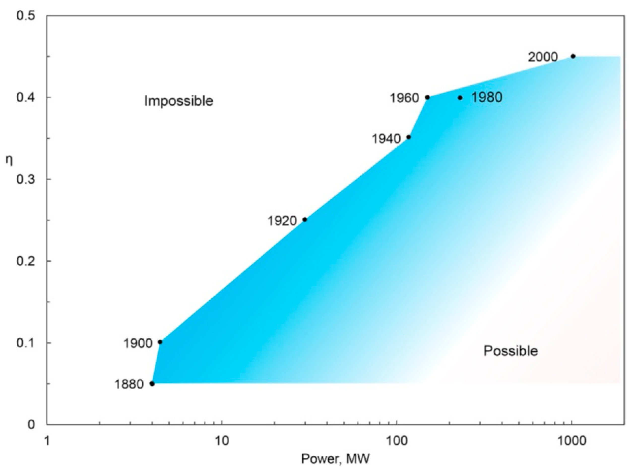
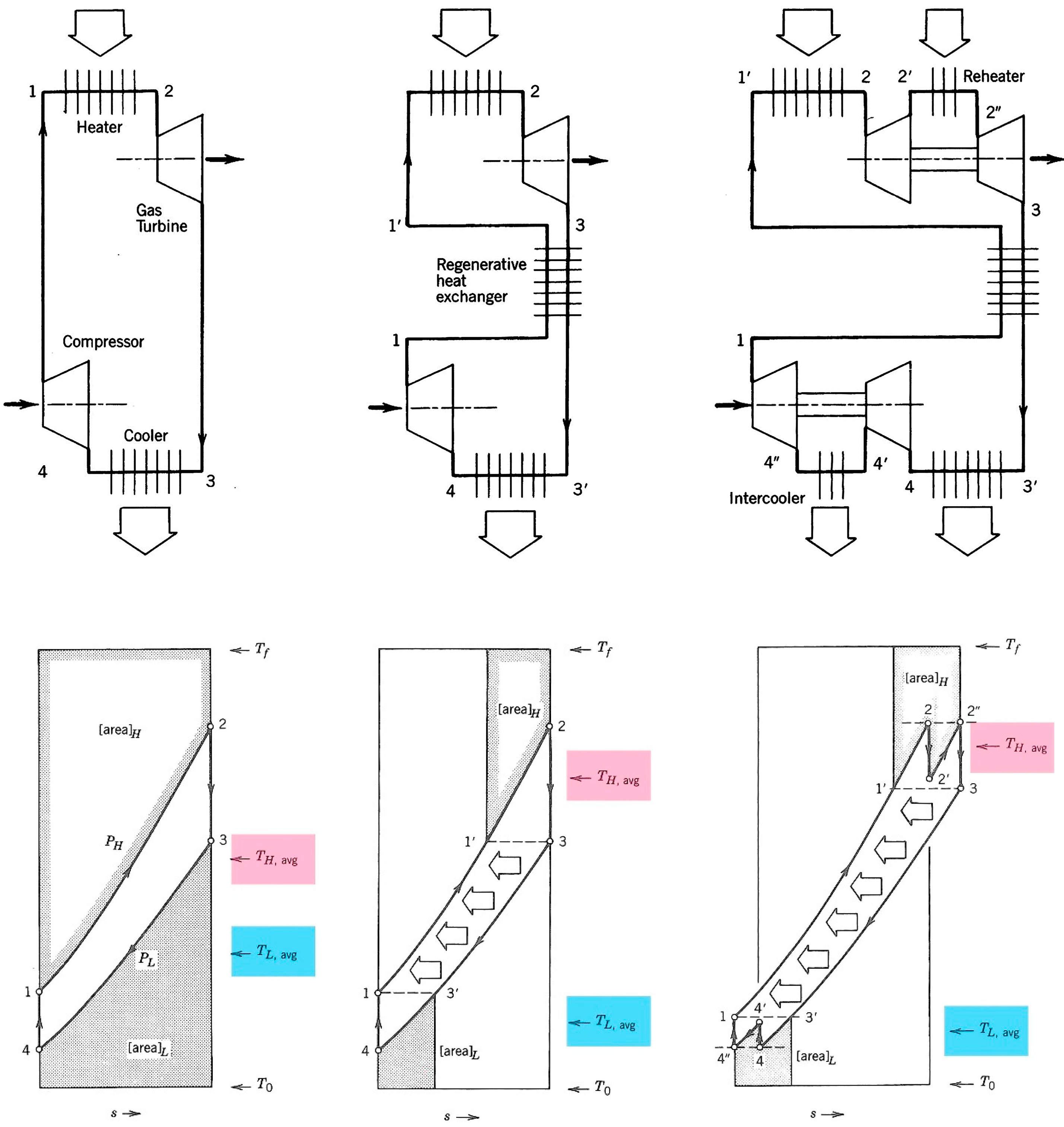
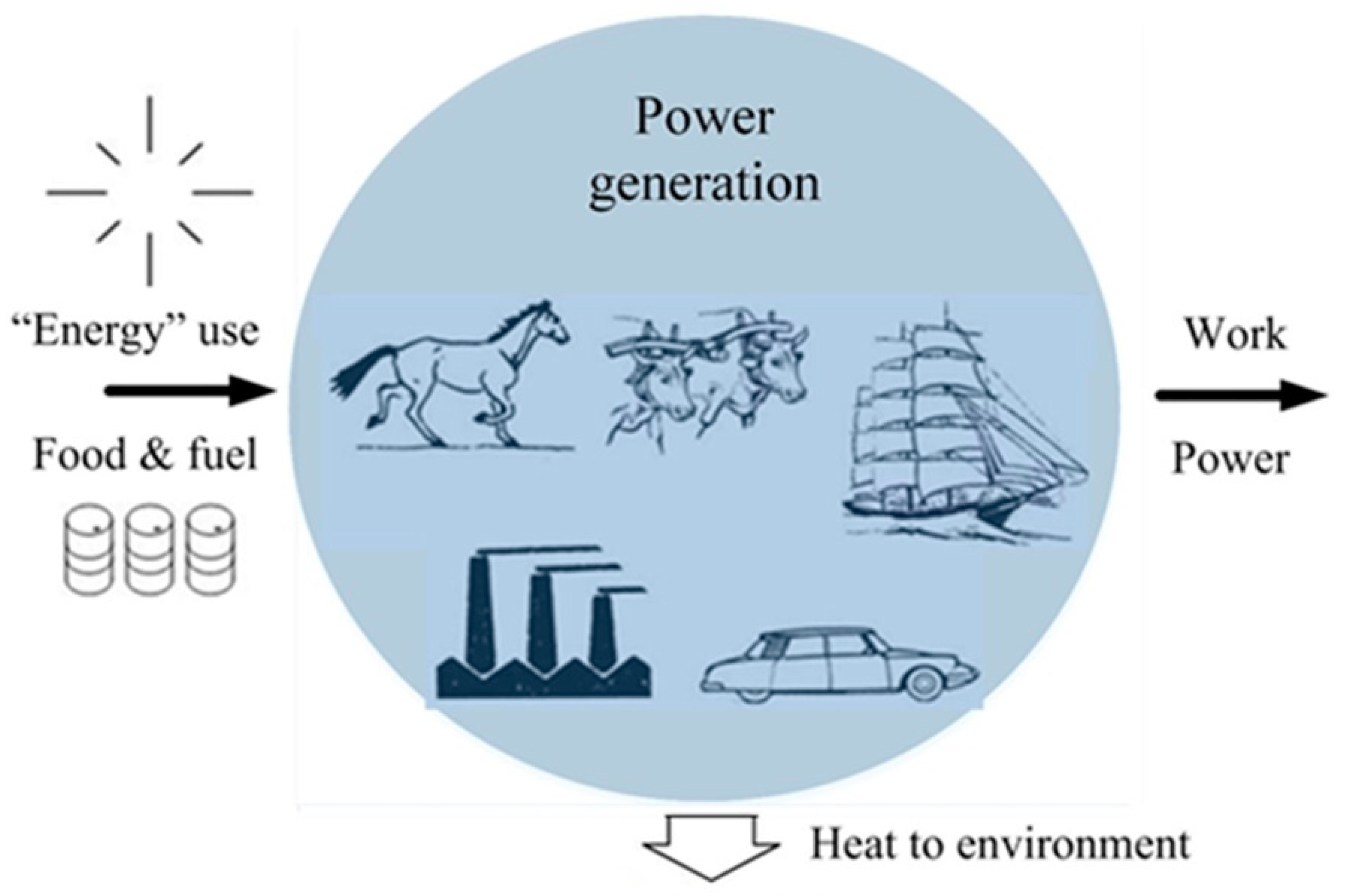
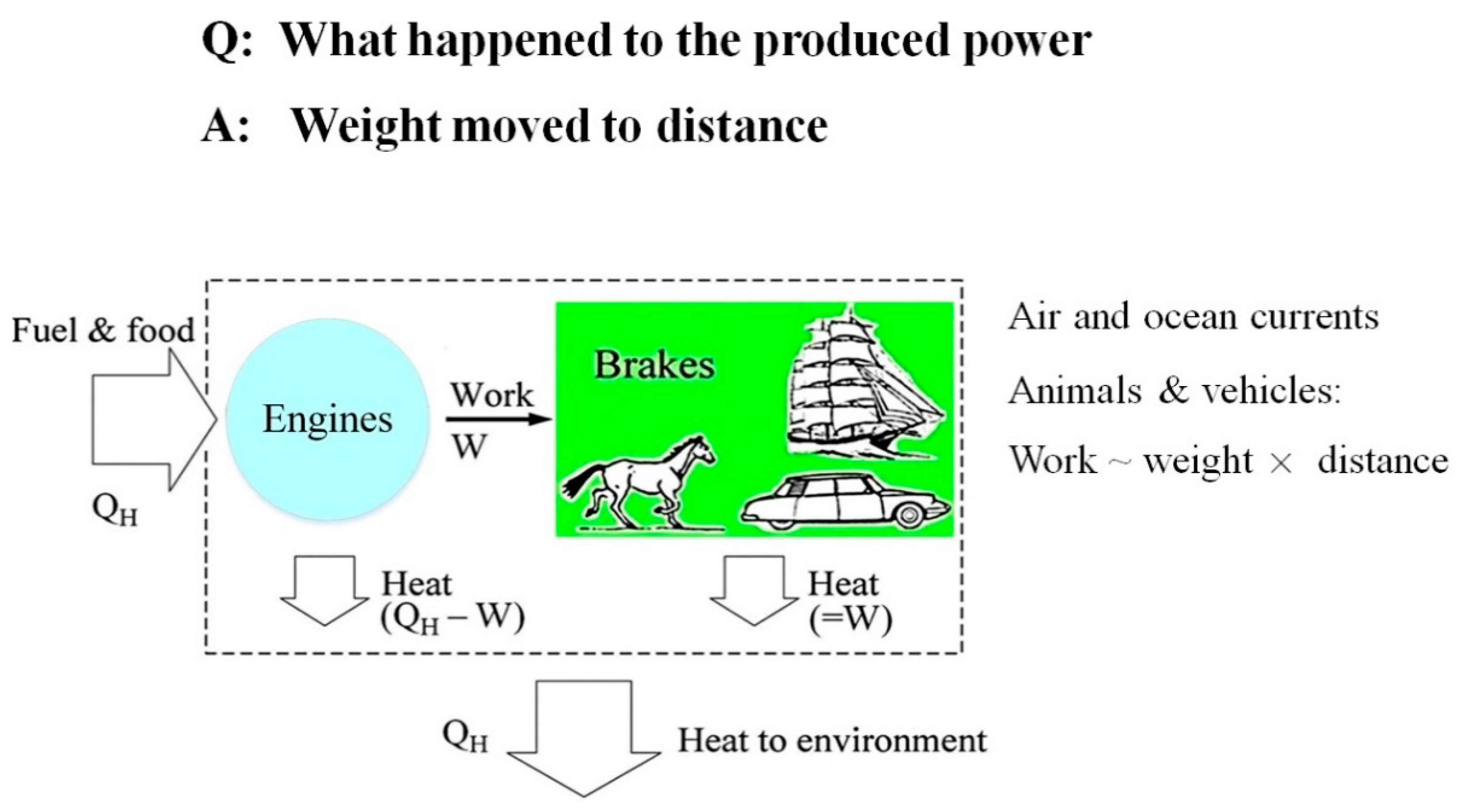
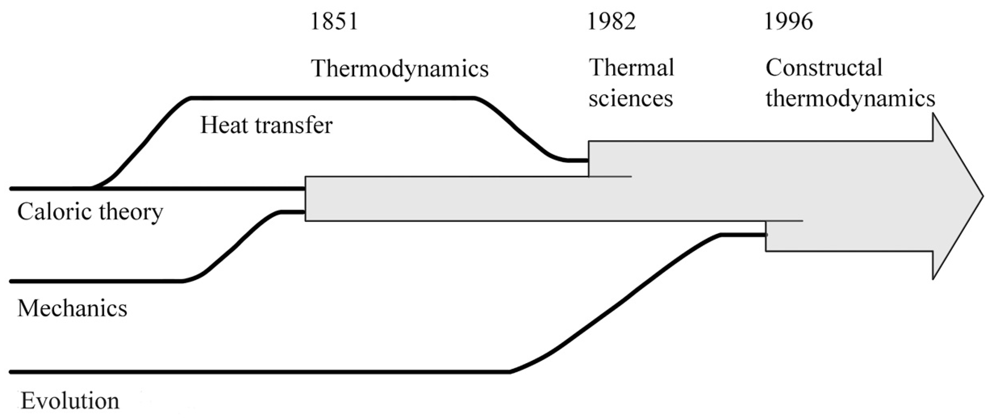
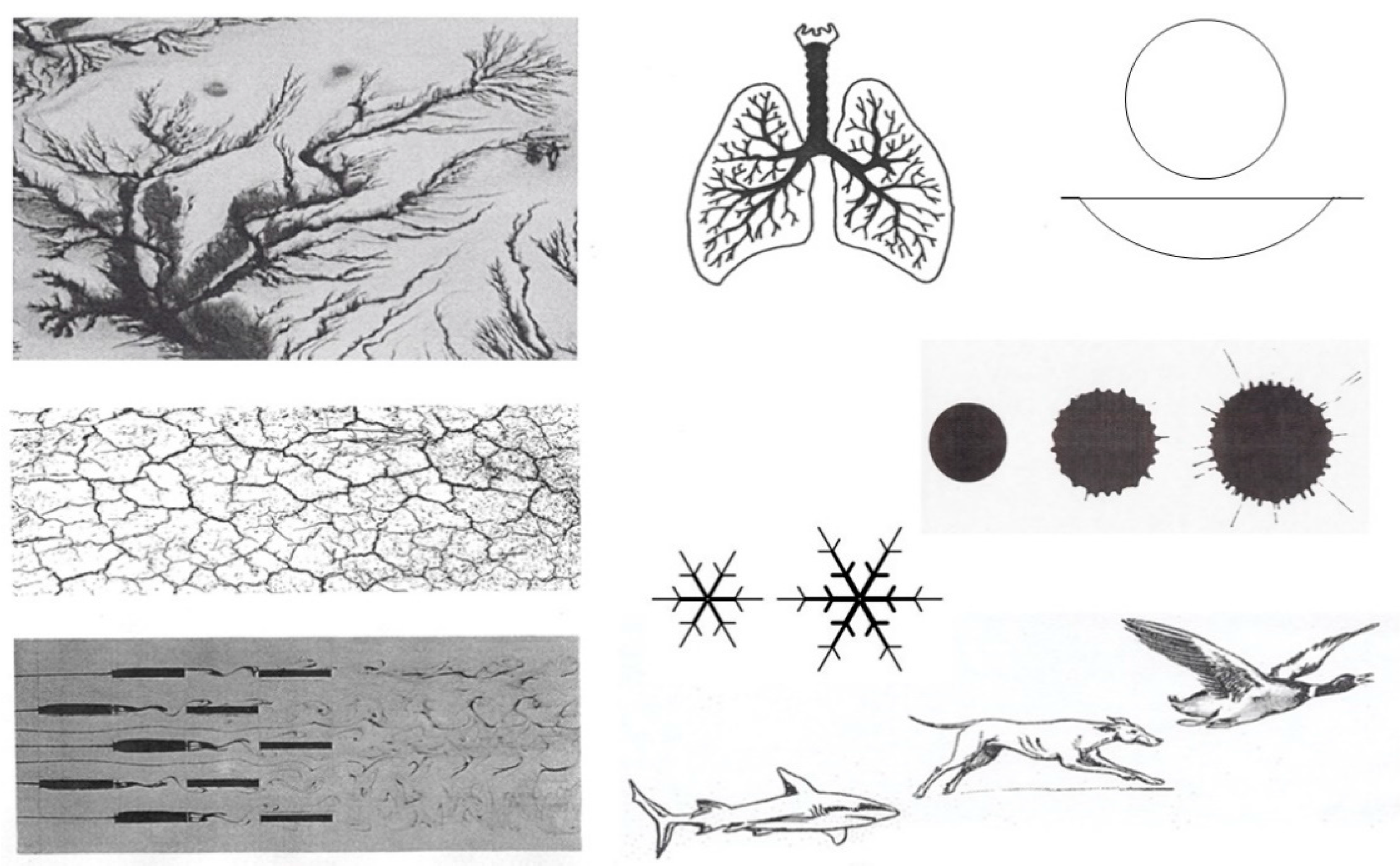
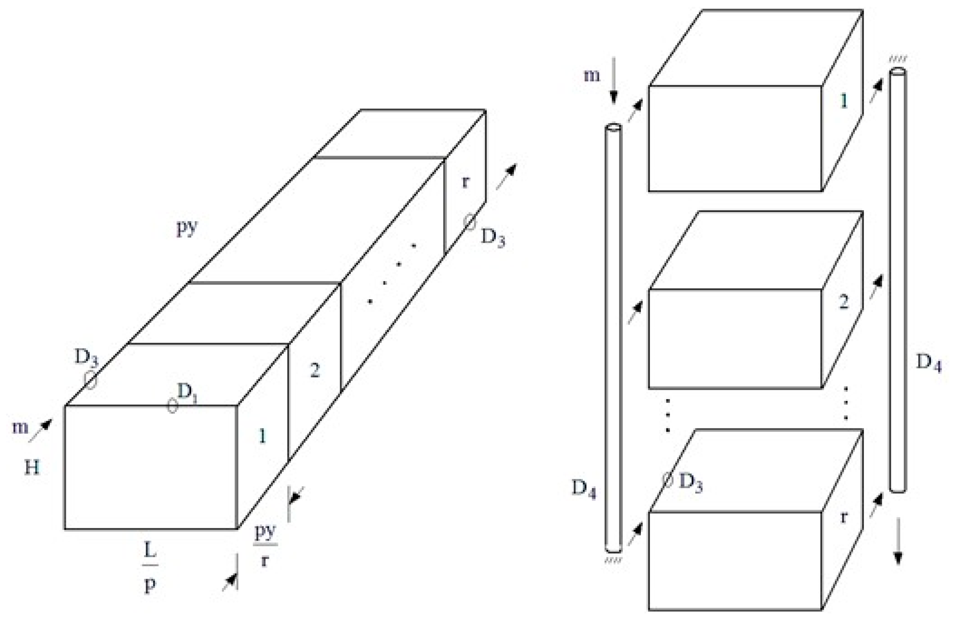
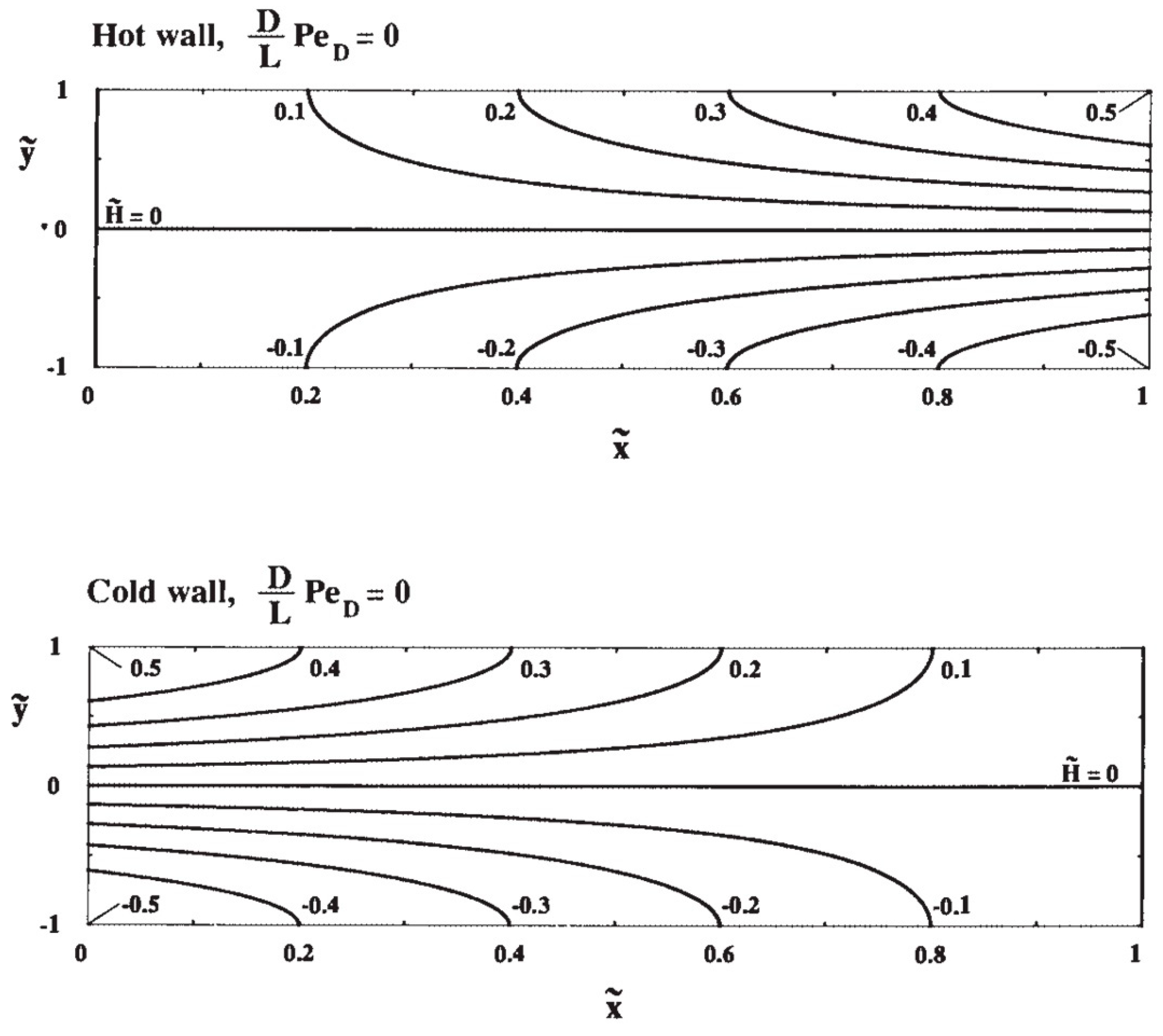
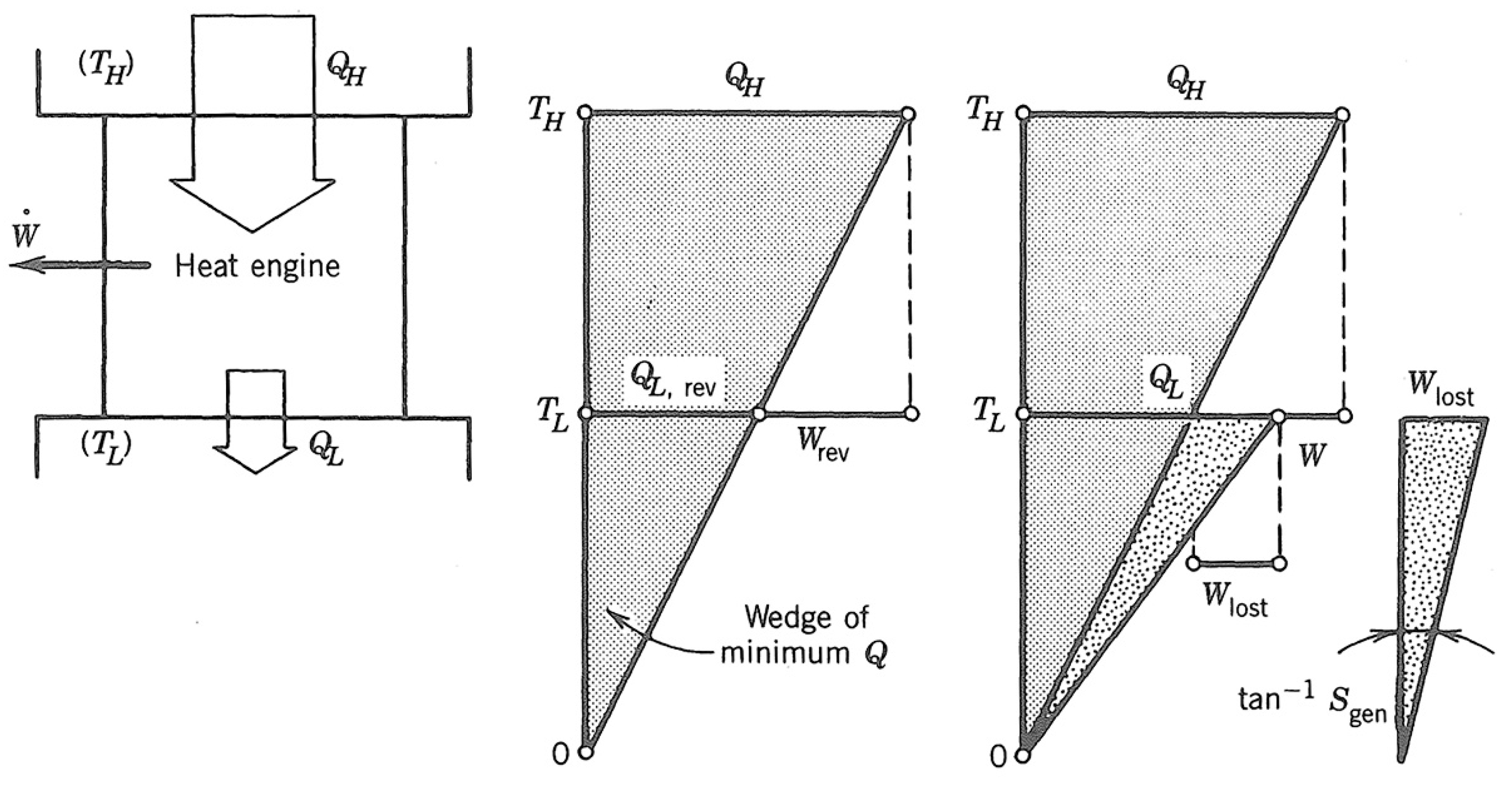
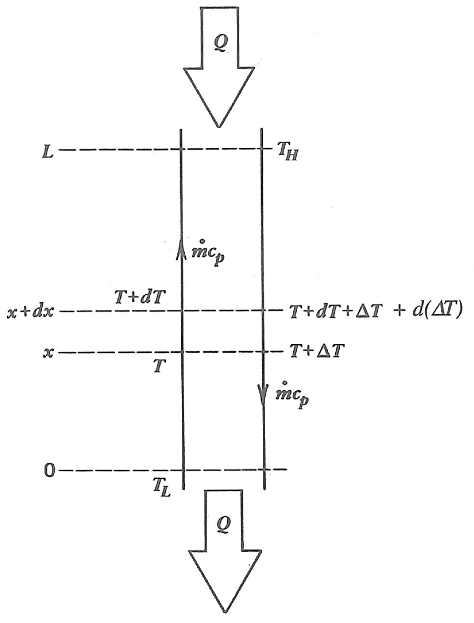
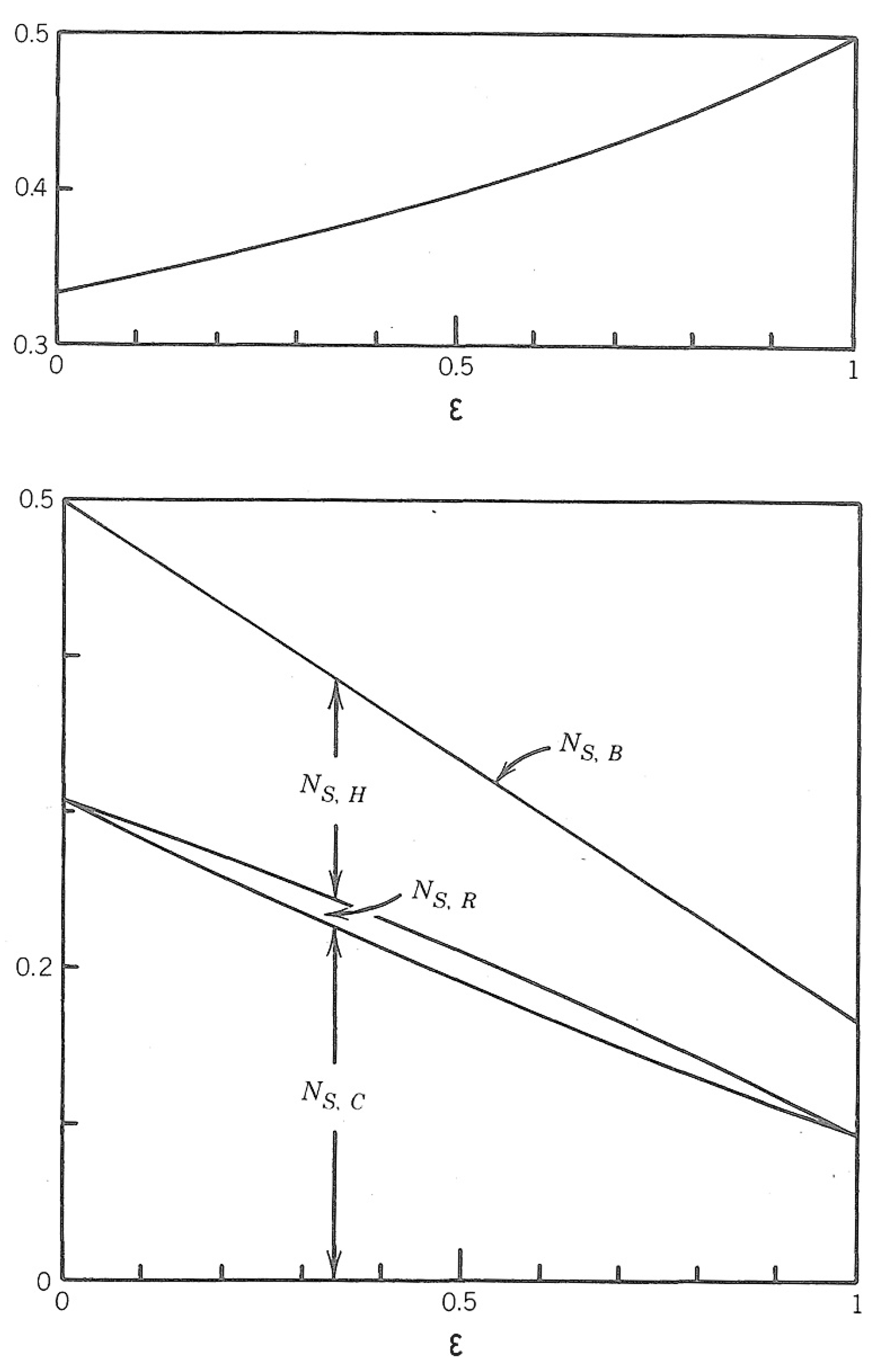
Figure 2.
Pyramids appear to have the same shape because shapes in this narrow range correspond to dry-stone constructions that require less effort [19].
Figure 2.
Pyramids appear to have the same shape because shapes in this narrow range correspond to dry-stone constructions that require less effort [19].

Figure 3.
The S-shaped history of power generation in the U. S., the total distance covered annually by vehicles in the U. S., and the world population [17].
Figure 3.
The S-shaped history of power generation in the U. S., the total distance covered annually by vehicles in the U. S., and the world population [17].

Figure 4.
The evolution of the design space of power plants, which is bordered from above by the second-law efficiencies of the new models that were adopted [3].
Figure 4.
The evolution of the design space of power plants, which is bordered from above by the second-law efficiencies of the new models that were adopted [3].

Figure 5.
The evolution of design space of power plants, the crest of which is marked by the rising first-law efficiencies of the most efficient models [3].
Figure 5.
The evolution of design space of power plants, the crest of which is marked by the rising first-law efficiencies of the most efficient models [3].

Figure 6.
The evolution of the configuration of gas-turbine power plants [21].
Figure 6.
The evolution of the configuration of gas-turbine power plants [21].

Figure 7.
The evolution of the configuration of systems that convert the useful energy of fuels and foods into work and power.
Figure 7.
The evolution of the configuration of systems that convert the useful energy of fuels and foods into work and power.

Figure 8.
The complete thermodynamic system driven by useful energy (Figure 7), showing that nature is a flowing tissue of engine + brake systems, which generate power and dissipate power through fluid flow and body movement.
Figure 8.
The complete thermodynamic system driven by useful energy (Figure 7), showing that nature is a flowing tissue of engine + brake systems, which generate power and dissipate power through fluid flow and body movement.

Figure 9.
The evolution and spreading of thermodynamics during the past two centuries [17].
Figure 9.
The evolution and spreading of thermodynamics during the past two centuries [17].

Figure 10.
Montage of evolutionary designs that have been predicted and explained based on the constructal law.
Figure 10.
Montage of evolutionary designs that have been predicted and explained based on the constructal law.

Figure 11.
The evolution of a river drainage basin in an erodible porous medium [132].
Figure 11.
The evolution of a river drainage basin in an erodible porous medium [132].

Figure 12.
The modular flow architecture that approximates two trees matched canopy to canopy [133,134].

Figure 13.
Heatlines in the fluid entering a duct with hot walls (top) and cold walls (bottom) [135,137].

Figure 14.
The temperature-heat (T-Q) graphic method [39,49,142] applied in this case to a closed system operating in cycles in communication with two temperature reservoirs (e.g., heat engine).

Figure 15.
Counterflow heat exchangers leak energy by convection in the longitudinal direction (from top to bottom in the figure) [39,146].

Figure 16.
The Brayton cycle power plant (Figure 6, middle) has three heat exchangers [heater (H), counterflow (R), and cooler (C)], and each generates entropy (NS). The total rate of entropy generation of the Brayton power plant (NS,B) decreases monotonically as the size of the counterflow (or ε) increases [21,148].

Publisher’s Note: MDPI stays neutral with regard to jurisdictional claims in published maps and institutional affiliations. |
© 2021 by the authors. Licensee MDPI, Basel, Switzerland. This article is an open access article distributed under the terms and conditions of the Creative Commons Attribution (CC BY) license (http://creativecommons.org/licenses/by/4.0/).
Share and Cite
MDPI and ACS Style
Bejan, A.; Tsatsaronis, G. Purpose in Thermodynamics. Energies 2021, 14, 408. https://0-doi-org.brum.beds.ac.uk/10.3390/en14020408
AMA Style
Bejan A, Tsatsaronis G. Purpose in Thermodynamics. Energies. 2021; 14(2):408. https://0-doi-org.brum.beds.ac.uk/10.3390/en14020408
Chicago/Turabian StyleBejan, Adrian, and George Tsatsaronis. 2021. "Purpose in Thermodynamics" Energies 14, no. 2: 408. https://0-doi-org.brum.beds.ac.uk/10.3390/en14020408
Note that from the first issue of 2016, this journal uses article numbers instead of page numbers. See further details here.