1. Introduction
Vibration-based energy harvesting technologies have been widely investigated with regard to the application of self-generated power devices that consume low amounts of electric power, such as internet of things sensors, by piezoelectric [
1,
2], electro-dynamic [
3], magneto-electric [
4,
5], and other strategies [
6,
7]. Magneto-piezo-elastic (MPE) energy harvesting is one type of emerging technology by which to induce the mechanical vibration of a piezoelectric beam using a magnetic coupling effect for electrical power generation [
8,
9]. It is of importance to transfer large amounts of strain into a piezoelectric material from an ambient vibrational energy source for better energy harvesting performance. As a typical structure to achieve this, the piezoelectric cantilever beam can combine a piezoelectric material and a substrate elastic beam, of which in-plane compressive and tensile strain energy can be effectively supplied to the piezoelectric material under bending movement.
It is generally known that the geometry of a piezoelectric cantilever beam will greatly affect its ability to harvest vibration energy [
10]. Piezoelectric energy harvesters generate power using a specific frequency (resonant frequency) at which maximized displacement is caused by vibration [
11,
12,
13]. To overcome the limitation of the narrow operating frequency, which is a characteristic of piezoelectric harvesters, there have been studies showing the characteristics of a wide operating frequency band there have been various studies [
14,
15]. The tip width of a cantilever beam has an inversely proportional relationship with the resonant frequency for a forced oscillatory condition. It was proposed by Baker and Roundy that varying the width of a trapezoidal-shaped beam can influence the energy efficiency [
16]. Sunithamani et al. reported that a micro-electro-mechanical system consisting of a trapezoidal cantilever with a trapezoidal cross-section offered more promising output power [
17]. The trapezoidal shape of the cantilever beam is currently regarded as superior to the conventional rectangular geometry in terms of distributing more uniform and stronger strain energy to the piezoelectric element, which can then result in intensified energy harvesting performance [
18,
19]. Nevertheless, its validation for practical energy harvester applications remains rare because it is not easy to determine suitable surroundings for taking advantage of the unique structure. Very few applications exist, such as a tire pressure monitoring system in the automotive industry, which represents the flagship application of the trapezoidal piezoelectric cantilever for energy harvesting [
20,
21]. A nonlinear distribution parameter model of piezoelectric wind energy harvester applications was also demonstrated, by which trapezoidal beams can harvest greater amounts of energy, especially at a low wind speed [
22]. However, a decrease in the tip width in the trapezoid results in an increase in the resonant frequency, which is never beneficial for more widespread usage of the trapezoidal piezoelectric cantilever in consideration of the relatively low frequencies (approximately less than 100 Hz) of ambient vibration sources in our environment [
23], such as vehicle motions at 0.5–62 Hz [
24,
25], trains at 5–80 Hz [
26,
27], and human motion at 1–42 Hz [
28,
29]. Recently, numerous studies have reported geometric designs and performance outcomes of trapezoidal piezoelectric cantilevers for energy harvester applications operating at low frequencies. Zhang et al. reported that a low-frequency piezoelectric energy harvester using a trapezoidal cantilever beam with magnetic coupling offered output power of 0.5 mW at 43 Hz [
30]. Wang et al. presented a low-frequency (0–30 Hz) broadband piezoelectric vibration energy harvester with a folded trapezoidal beam [
31]. Umegaki et al. also demonstrated that an optimized trapezoidal piezoelectric vibration energy harvester of which the thickness ratio of the piezoelectric film to the substrate is 0.4:1 could generate an output power of 3 μW at 77 Hz [
32]. A hybrid piezoelectric-electromagnetic energy harvester was also proposed for a low-frequency-vibration environment [
33].
Rotational energy harvesting technologies using piezoelectric transduction and magnetic coupling have also been reported in papers titled Rotational energy harvesting using bi-stability and frequency up-conversion for low-power sensing applications: Theoretical modelling and experimental validation [
34], Analytical and experimental investigation of the centrifugal softening and stiffening effects in rotational energy harvesting [
35] and A rotational piezoelectric energy harvester for efficient wind energy harvesting [
36]. In this work, “horizontally assembled trapezoidal piezoelectric cantilevers driven by magnetic coupling force are proposed for rotational energy harvester applications”. The magnetic coupling force can make a robust trapezoidal piezoelectric cantilever more deflectable for better power generation, irrespective of whether its natural frequency is high or not. The geometry of the proposed trapezoidal piezoelectric cantilever array and the overall optimized configuration of the novel energy harvester are introduced. Its energy harvesting performance was demonstrated as a Savonius-type wind energy harvester with variations of the wind speed for practical applications.
2. Materials and Methods
A commercial lead zirconate titanate (PZT) powder (AC750, Hayashi Chemicals, Japan), with good piezoelectric properties and a mechanical quality factor (Q
m) of 138, an electromechanical coupling factor (k
p) of 61.7%, a piezoelectric charge constant (d33) of 520 pC/N, and a piezoelectric voltage constant (g33) of 24 × 10
–3 Vm/N [
37], was prepared to fabricate the piezoelectric thick film by a conventional tape casting process. The PZT powders were mixed with ethanol (Samchun Pure Chemical, Korea), toluene (Samchun Pure Chemical, Korea), polyvinyl butyral (BM-SZ, Sekisui, Japan), dibutyl phthalate (Daejung Chemical & Metals, Korea) and a dispersant (BYK-111, BYK-Chemie GmbH, Germany) at a certain ratio for the tape casting slurry. Subsequently, the PZT slurry was ball-milled by zirconia ball media with various diameters (
ϕ = 1, 3, 5, 10, and 15 mm) at 150 rpm for 24 h to attain a uniformly dispersed slurry. After ball-milling, the slurry was uniformly sieved by a fabric mesh, defoamed in a vacuum degasser under a vacuum of 760 mmHg for one hour, and aged at 10 rpm for 12 h for stabilization. Thereafter, PZT green sheets were successfully fabricated with a constant thickness of 40 μm using a doctor-blade casting machine (TCA-2000, Techgen, Korea). A planar electrode pattern was thoroughly printed onto the PZT green sheet using Ag paste (WTAPPL7-1, Winner Technology, Korea) for transversal piezoelectric energy harvesting.
Nine PZT green sheets (with the outer PZT sheets having the printed electrode) were laminated at 60 °C using a laminator (Keko, Slovenia). The laminated sheets were then cut into a trapezoidal shape and successfully co-fired at 850 °C for two hours after undergoing warm isostatic pressing (WIP) at 25 MPa and 65 °C for 20 min. In order to fabricate a trapezoidal piezoelectric bimorph cantilever (TPBC), two co-fired PZT laminates were completely bonded to both sides of a stainless-steel elastic plate with a trapezoidal shape using an adhesive epoxy. Curing was done on the TPBC at 65 °C under 0.35 MPa for 20 min using an autoclave (PO1-700-20, PHOS-ENTECH, Korea), after which a cuboidal permanent magnet (PM) with a size of 10 mm (width), 10 mm (length), by 3 mm (height) was attached at the end tip of the cantilever beam as a magnetic mass. Detailed parameters for the trapezoidal piezoelectric bimorph cantilever are summarized in
Table 1.
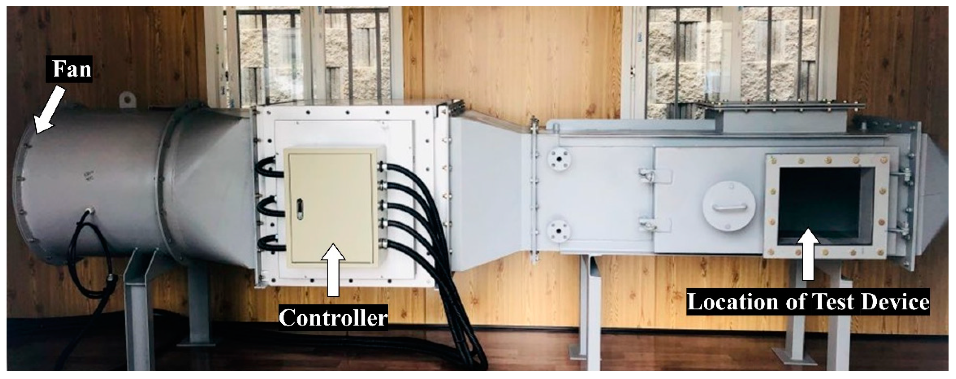
The displacement of a single TPBC deflecting with variation of the rotor’s rotation speed was measured by a laser Doppler vibrometer (MICROTRAK7000, MTI Instruments Inc., Albany, NY, USA). The rotor’s rotation was automatically controlled by an electric motor (SST59D530X, Shinano Kenshi, Japan) and by the printed circuit board of a speed controller. The electrical outputs of the voltage, current, and power for each TPBC and the TPBC array were measured with a variable resistor by a digital power meter (WT310, Yokogawa, Japan). The energy harvesting performance for practical applications was tested through a wind energy harvester that can be operated by Savonius turbine blades. Its wind energy harvesting performance was estimated in a custom-made wind tunnel where the wind speeds are regulated by a digital controller. An anemometer (Testo 416, Testo, Germany) was utilized to measure the wind speed at the very front of the wind harvester under test. The wind tunnel system to supply various winds with speed up to 20 m/s is shown in
Figure 1. In the wind tunnel, with a cross-sectional area of 50 × 50 cm, the proposed wind energy harvester was characterized to evaluate energy harvesting performance. An electric fan with a diameter of
ϕ680 can introduce the required wind with specifications of flow uniformity within approximately 3% and a blockage ratio of 15%. The rotational energy harvester proposed in this work was configured by a dodecagonal stator with a horizontally assembled trapezoidal piezoelectric cantilever array and a circular disk rotor, with the vertical axis shared by the stator and the rotor. Its detailed description is introduced in the following section and is shown in
Figure 2. In order to evaluate the energy harvesting characteristics of the proposed rotational energy harvester, the TPBC array was connected in a parallel electric circuit with a rectifying circuit on each TPBC.
3. Results and Discussion
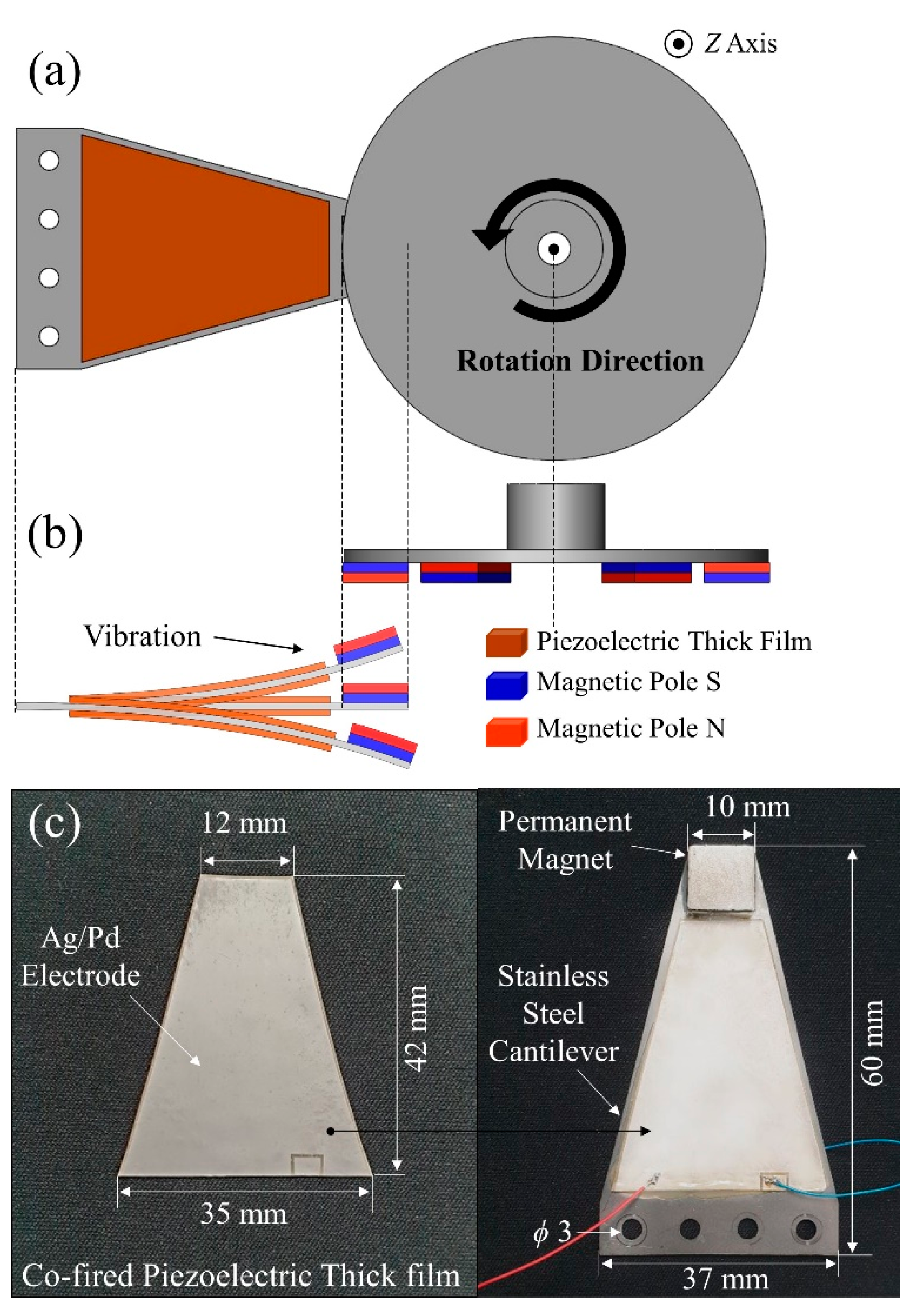
Figure 2a shows an illustrated schematic top-view image of a trapezoidal piezoelectric bimorph cantilever interacting with the rotor disk for magneto-piezo-elastic energy conversion. As will be introduced in the following discussion and as shown in
Figure 3, the cantilever is one of six trapezoidal cantilevers comprising the proposed rotary energy harvester. The trapezoidal cantilever is tightly fixed with a rigid body at a position denoted by four holes on the trapezoidal substrate. The disk corresponding to a rotor can rotate along the z-axis, of which the direction is perpendicular to this page, as shown by the counter-clockwise circular arrow. The magnetic coupling effect can arise between two interacting PMs; one is the proof-mass of the clamped cantilever and the other is a rotating magnet affixed onto the bottom surface of the rotor disk. As an example showing the magnetically attractive interaction, a side-view image of the schematic of
Figure 2a is also depicted as
Figure 2b. The deflected piezoelectric cantilever can generate electricity via the transferred strain of the piezoelectric thick films attached to the deflected substrate beam under the effective magnetic field. For a magnetically driven vibration mode, the trapezoidal piezoelectric cantilever beam was designed to operate in the transverse mode, where the polarized direction is perpendicular to the direction of the applied stress. A planar electrode coated on both sides of a piezoelectric film is typically utilized to implement the transverse mode for electrical power generation.
Figure 2c exhibits the Ag/Pd-electrode printed trapezoidal piezoelectric thick film and the cantilever beam with the attached piezoelectric thick film. The trapezoidal piezoelectric thick film, made of a conventionally used lead-zirconate-titanate (PZT) ceramic, was successfully obtained as designed in consideration of shrinkage during a co-firing process. It should also be noted that the Ag/Pd electrode was fully printed onto the surface of the piezoelectric film while assuming a homogeneous and clear surface. A small rectangular tab placed on the long side of the trapezoid serves as an electrical connection with the other electrode printed behind the film. Although the surface of the cantilever beam was slightly stained with the adhesive epoxy after the piezoelectric film was attached to the cantilever beam, it was not significant because the electrical output signals coming from the piezoelectric element were never affected by surficial epoxy blurring. Detailed numerical dimensions are also provided in
Figure 2c.
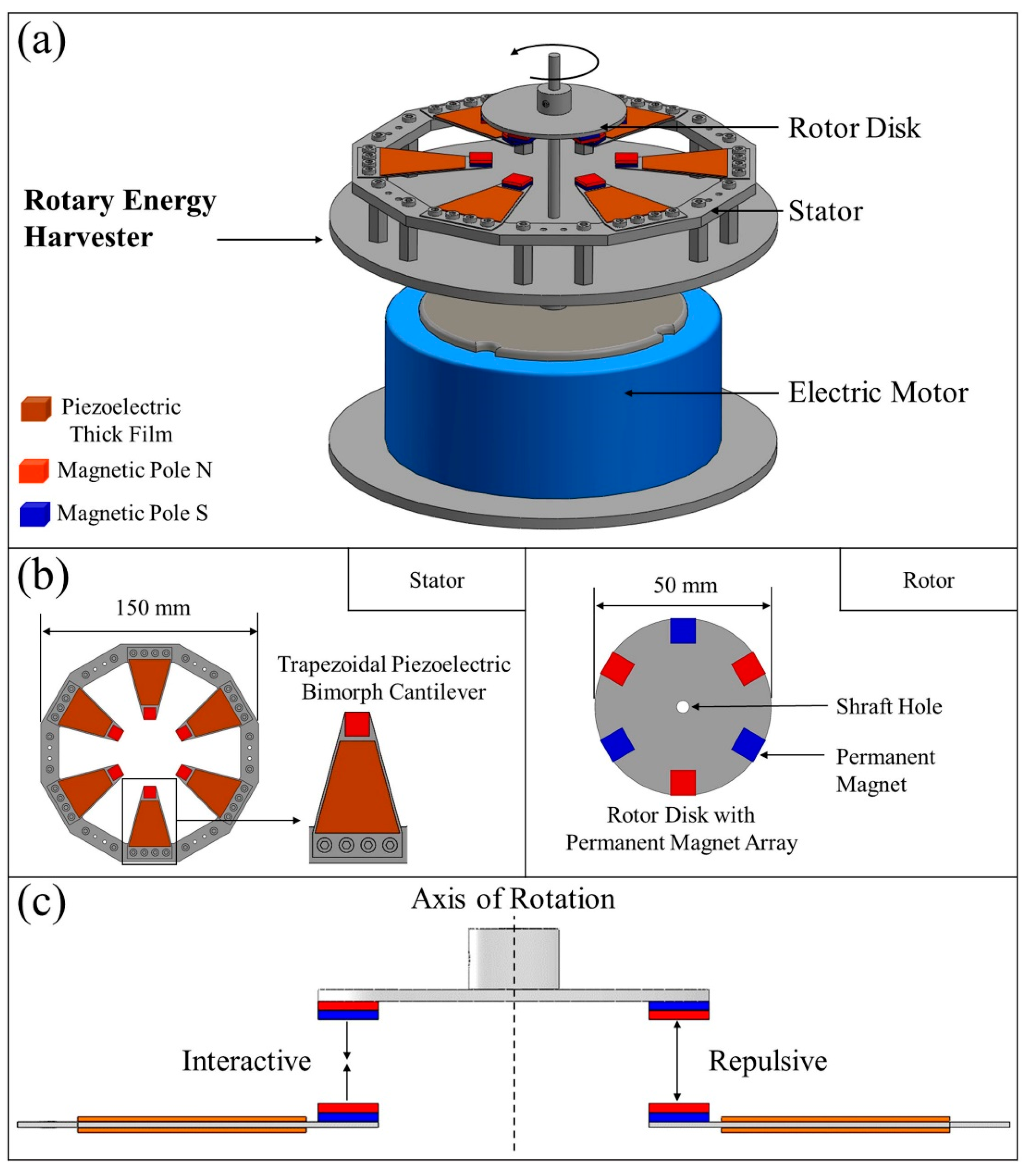
Figure 3a also shows a schematic illustration of the test equipment used for the evaluation of the power generation capability of the proposed energy harvester. As mentioned above, all six trapezoidal piezoelectric cantilevers used here constitute a dominant part of the stator to generate electricity from the proposed energy harvester. The cantilevers are horizontally aligned with the vertical axis in the center of the harvester and tightly clamped onto the dodecagonal frame, where its center is shared with the vertical center z-axis of the rotor disk. The proposed energy harvester was configured to generate electrical energy transferred from the rotational energy by the rotor disk on the basis of a magneto-piezo-elastic energy conversion mechanism, which can be helpfully referred to in a previous report [
38]. Apart from the stator, the rotor disk with the PM is hung with a rigid shaft capable of rotating with rotation speeds controllable by an electric motor. A top-view image of the dodecagonal stator and a bottom-view image of the disk rotor are provided in
Figure 3b. For the stator, the longer side of the trapezoidal cantilever is strongly adhered to one side of the dodecagonal frame by four screwed bolts, with the other side having one PM. Each PM has strong magnetism and so, as the distance between each PM gets closer, strong magnetic interference occurs. Such magnetic interference directly affects the harvester output performance and needs to be adjusted. When all the cantilevers are mounted on the dodecagonal frame, the minimum distance between the PMs attached to the cantilever is about 3 mm, and considerable magnetic force is generated. Repulsive forces act on each other because the magnets of the cantilever are arranged to have the same polarity, and the deformed state of the cantilever is maintained. To prevent this problem, six cantilevers were mounted on a dodecagonal frame to ensure a distance at which magnetic interference was negligible. Magneto-piezo-elastic energy conversion is closely related to the number and placement of magnets. In the case of circular motion, some pairs of PMs must be in a state of magnetic-equilibrium. Here, the magnetic-equilibrium state is one in which magnetic forces of the same magnitude act at the same time and the same number of attractive forces and repulsive forces can act simultaneously. As for the number of PMs that satisfies these conditions, an even number of PMs must be applied to each rotor and stator. If magnetic-balancing is not achieved, the output power decreases due to the resistive torque generated in the asymmetric structure.
Each cantilever beam has two multilayer piezoelectric thick films on both of its surfaces, indicating a piezoelectric bimorph cantilever. Every cantilever is positioned at an identical distance from the center axis at a rotation angle of 60°, and all of the tip-mass PMs have the same polarity. There is no magnetic interaction among the tip-mass PMs due to the sufficient distance between the two neighboring cantilevers. On the other hand, the polar arrangement of the PMs of the rotor disk with a diameter of 50 mm differs from that of the cantilever array of the stator. Although the PMs are distributed uniformly with a 60° angle of rotation, similar to the arrangement of the tip-mass PMs, the polarities of two PMs placed along a direction crossing the center axis are opposite to each other. Such a polarity arrangement is responsible for facilitating the rotor’s rotation by the simultaneous action of attractive force and repulsive force occurring between the rotator and the stator.
Figure 3c shows the optimized PM configuration of the energy harvester with two magnetically coupled PM pairs in a static state.
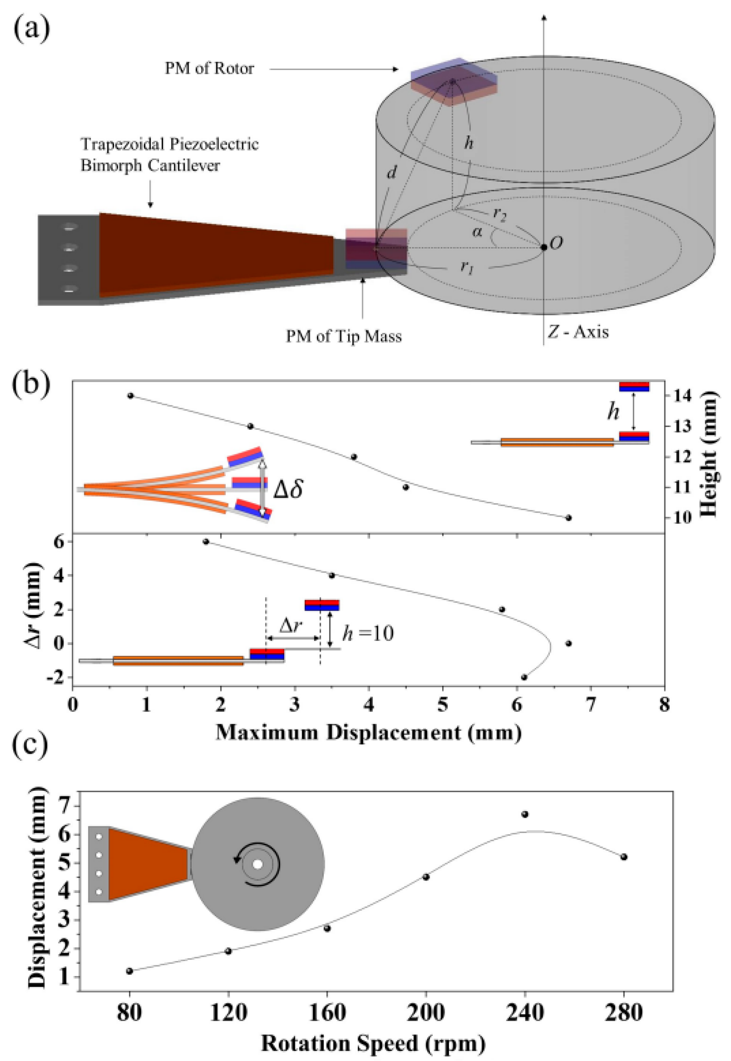
In order to obtain the best performance from the proposed energy harvester, the distance between two magnetically coupled PMs must be optimized. Using a cylindrical coordinate system is an appropriate way to determine the best geometrical condition because the rotor’s PM moves rotationally while the stator’s tip-mass PM maintains a constant distance from the vertical z-axis, as shown in
Figure 4a. In the coordinate system, it is important to determine the radius and height of the rotor disk because the rotor’s PM can directly interact with the counterpart tip-mass PM of the stator. If the origin (
O) of the cylindrical coordinate system is assumed to be on a horizontal plane across the center of the stator’s tip-mass PM, the location of the rotor’s PM can be expressed as
r2 and
h, which correspondingly indicate the radius and height of a horizontal circle crossing the center point of the rotor’s PM. In addition,
r1 represents the radius of a horizontal circle crossing the center point of the stator’s PM. The inclined angle between two vectors of
Or1 and
Or2 is denoted by
α. In contrast to the dynamic parameter of
α dependent on the rotational speed of the rotor, the radial difference ∆
r (
r1−
r2) as well as
h are controllable static parameters. Therefore, it is necessary to determine the optimum values of
h and
r2 to achieve the best energy harvesting performance, as
r1 is predetermined as a static parameter, as mentioned with regard to the dimensions of the dodecagonal frame, including the trapezoidal cantilever array, in
Figure 3b. The resultant experimental data shown in
Figure 4b present the deflection behavior of the trapezoidal cantilever when
h and ∆
r vary.
Figure 4b exhibits the deflection (∆
δ) of the end tip of the trapezoidal beam under alternating attractive and repulsive magnetic force as a function of the height, radius and rotation speed of the rotor disk for the energy harvester. The linearly increasing tendency of the maximum displacement with decreases in the height and the radius was examined. As the magnetic field intensity between two cuboidal PMs is even stronger when their own larger surfaces face each other, the arrangement of PMs was determined to be identical along the vertical direction but different along the horizontal direction. In these cases, the rotation speed of the rotor was held constant at 240 revolutions per minute (rpm). At a height exceeding 14 mm, the beam was not deflected due to the excessive distance out of the effective magnetic field. The optimized height of the rotor disk is evaluated as approximately 10 mm, where the piezoelectric cantilever beam cannot only be highly deflectable but also mechanically stable without the occurrence of cracks. It is also evident that the highest value of ∆
δ can be obtained when ∆
r approaches zero at the optimum height of 10 mm, implying the best arrangement of the PM pair. This displacement change can be known through a change in magnetic force generated between PMs of the rotor and cantilever. The magnetic force between two PMs can be calculated through a mathematical model with the equation below [
39,
40],
where
J and
J′ are the magnetization of each PM,
(approximately 1.26 × 10
−6 H/m) is the permeability of free space,
ϕ is a function of magnet dimensions and distance, and the parameters
i,
j,
k,
l,
p, and
q are equal to 0 or 1 [
39]. According to the above Equation (1) to (4), when
h = 10 and Δ
r = 0, and where the distance between two PMs is at its minimum, a strong magnetic coupling force is formed between the two magnets. When Δ
r is −2, the maximum deformation is about 6.1 mm, which is about 0.3 mm higher than when Δ
r is 2. It can be expected that when the cantilever is deformed upward in a situation in which attraction is generated, when Δ
r is −2, a relatively strong magnetic force will be generated as the distance between the magnets decreases, resulting in high maximum deformation.
Figure 4c exhibits the deflection (∆
δ) of the end tip of the trapezoidal beam as a function of the rotor’s rotation speed from 80 rpm to 280 rpm. The highest displacement of approximately 6.7 mm at 240 rpm was depicted in the supplied rpm range. This implies that the trapezoidal cantilever has harmonic resonance at close to 240 rpm, which is identical to 24 Hz during magnetically forced oscillation. Accordingly, it can be expected that the exceeded rpm rather deteriorates the output energy harvesting performance of the piezoelectric cantilever due to the tip-mass PM’s reduced response time. If 240 rpm showing the highest peak is the first harmonic oscillation, the best power generation will be also obtained at 240 rpm because the deflection of the cantilever beam will be mitigated under the additional harmonic oscillations.
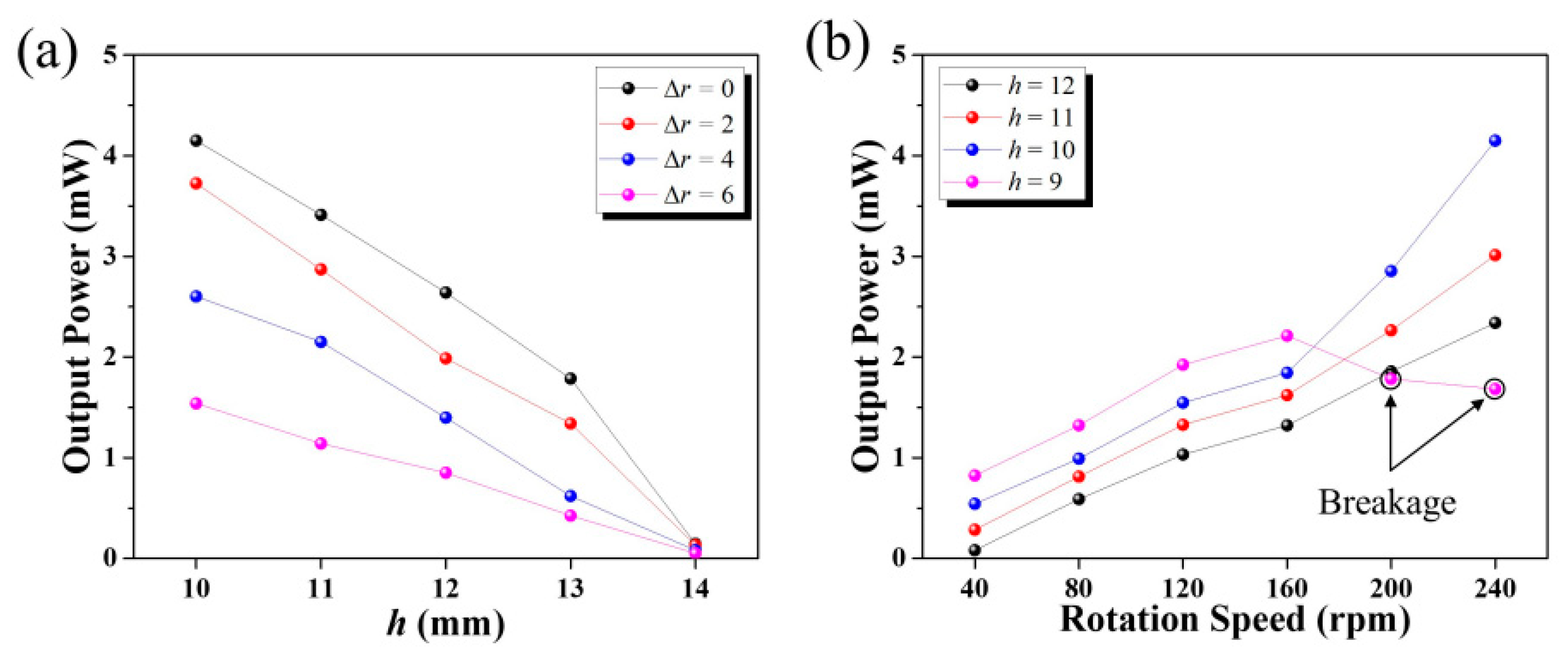
Figure 5a shows the output power of a trapezoidal piezoelectric bimorph cantilever with variation of the radius gap of ∆
r and the rotor’s height of h in the proposed energy harvester. For the experiment, the rotation speed was maintained at a level as high as 240 rpm and the two piezoelectric films were electrically connected with a serial circuit to prevent the disappearance of the superposed electric output signal by two stress-induced piezoelectric films with simultaneously concave and convex shapes. As can be expected from the deflection behavior of the cantilever beam, it was confirmed that the highest output power was achieved at a height of 10 mm for every condition of ∆
r from 0 to 6 mm. The output power also tended to increase with a decrease in ∆
r and reached a maximum of 4.2 mW at ∆
r = 0.
Figure 5a exhibits the rpm-dependent output power of the trapezoidal piezoelectric bimorph cantilever with variation of the rotor’s height,
h. A linear increase in the output power was observed with an increase in the rotation speed from 40 rpm to 240 rpm when the height is sufficiently high at as much as 11 mm and 12 mm. In addition, an enhancement of the output power was noted with a decrease in the height from 12 mm to 9 mm due to the enforced magnetic force. The output power at the height of 10 mm increased drastically when rotation speed of 160 rpm was exceeded but underwent a slight decrease due to the breakage of the piezoelectric film at the decreased height of 9 mm. The outbreak of cracks in the piezoelectric film considerably deteriorated the power generation due to the weakened strain. All of the output power characteristics dependent on the rotation speed and height are also summarized in
Table 2. In order to analyze the deformation and breaking characteristics of TPBC in more detail, a universal testing machine (UTM) was used to analyze these characteristics through linear forces rather than periodic forces. Referring to
Figure 6 when the load reaches 6.3 N, a drastic decrease in load occurred and, subsequently, the load started again to increase. At this time, the piezoelectric film broke with deflection of approximately 4.4 mm, identical to half of
∆δ. As already shown in
Figure 4 of the original manuscript, when the height (
h) became 10 mm, the maximum displacement was 6.7 mm. When the h decreased further to 9 mm, the maximum displacement of the endurable cantilever beam was similar to two times of deflection at the breakage for the trapezoidal piezoelectric bimorph cantilever under test, as shown in
Figure 7. In this case, low rpms of less than 200 can cause the cantilever to endure for some time, as already shown in
Table 2 of the manuscript. However, further increase in rpms (from 200 and 240) could result in enhanced fatigue of the cantilever and, consequently, lead to its destruction.
It should be also considered that the proposed energy harvester can start rotating spontaneously to generate electrical power from ambient energy sources. The start-up condition can be experimentally validated by an evaluation of the resistance torque with variation of the rotation speed because the start-up torque should surpass the resistance torque to activate the rotation of the blades. The resistive torque can be theoretically calculated using Equation (1) based on existing theory related to magnetic interaction force of a pair of cubic PMs. Previous works can be referenced to calculate the resistance torque levels of a piezoelectric cantilever driven by magneto-piezo-elastic energy conversion [
38]. According to Equation (5) below, the total resistance torque (
T) can be calculated using the cross product of
l and
F,
where the directional magnetic interaction force (
Fx and
Fy) can also be extracted by applying
ϕx and
ϕy to Equation (2), respectively.
The results can also provide the theoretical resistance torque of the proposed wind energy harvester with consideration of
Fx,
Fy. The total resistance torque will depend on the variation of the distance between the magnetically coupled PMs [
39]. As the calculated resistance torque can be expressed in the time domain readily according to the rotation speed, it was plotted as a function of the rpm and the height (
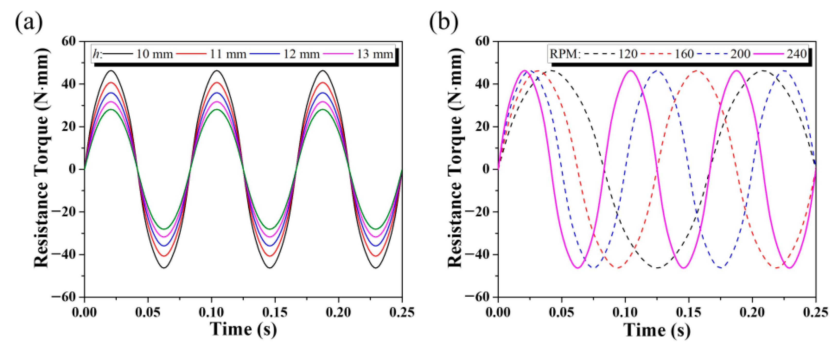
h) of the rotor disk under the attractive and repulsive magnetic field effects, as shown in
Figure 7a,b, respectively. In
Figure 7a, sinusoidal waves with the same period were obtained for all cases when varying the height from 10 mm to 13 mm when the rotation speed was constrained to 240 rpm. The increasing change of the height resulted in inversely proportional amplitude variation of the resistance torque. The absolute value of the resistance torque was maximized at 46 mN·m at an h value of 10 mm and was reduced to 28 mN·m when
h reached 13 mm. The higher resistance torque may negatively influence the rotor’s rotation considering a magnetically coupled single piezoelectric cantilever, but it will definitely be compensated for by the configuration of the piezoelectric cantilever array when balancing the magnetic forces of attraction and repulsion at the opposite sites, as shown in
Figure 3b. The start-up wind speed is an important factor for an airflow wind energy harvester using turbine structures. According to previous reports, there can be an option for usage of a radially movable PM or optimal selection of number/arrangement of PM to regulate start-up wind speed [
41,
42]. In this work, an optimal arrangement of magnetic polarity was applied to lower the starting wind speed by reducing resistance torque at the beginning. In more detail, if several PMs with magnetically attractive force were placed at positions on a dodecagonal frame, several other PMs with magnetically repulsive force were aligned at exactly opposite positions. In this work, all PMs stuck to the six trapezoidal piezoelectric bimorph cantilevers interacted with PMs on the rotor plate, maintaining magnetic equilibrium. This arrangement can reduce the start-up wind speed the lowest possible level. In this work, it was experimentally demonstrated that the starting wind speed of the proposed wind harvester was 4 m/s. This is compatible with the results showing that the maximum displacement and the highest output power of the trapezoidal piezoelectric cantilever were achieved at the reduced height of 10 mm without breakage of the piezoelectric film, as already shown in
Figure 4b and
Figure 5b. As indicated in
Figure 7b, no change was observed in the amplitude of the resistance torque at the constant h of 10 mm when the rotation speed was varied from 120 rpm to 240 rpm. This implies that the resistance torque is irrelevant with regard to the rotation speed once the proposed energy harvester starts to rotate. Therefore, it is considered that h is regarded as a more dominant parameter not only for the start-up of the energy harvester but also for better energy harvesting performance after start-up.
In this work, an energy harvester with consideration of the optimum design conditions was demonstrated for wind energy harvester applications.
Figure 8a,b show photographic images of the fabricated wind energy harvester with the trapezoidal bimorph cantilever array, showing the top view and a tilted view, respectively. In order to obtain the best energy harvesting performance, a 10 mm height of
h and no radius gap (∆
r = 0) were applied to the wind energy harvester as the pertinent design parameters. The magnetically coupled trapezoidal piezoelectric cantilever array is shown at the dodecagonal frame of the stator in
Figure 8a. At the top of the energy harvester in
Figure 8b, the rotor disk holding the PMs on its bottom surface is shown to be connected to the center shaft along the vertical z-axis. Two custom-made acrylic plates as a top and bottom plate were used to support the double-stacked Savonius turbine blade and the dodecagonal stator frame, along with four stainless-steel pillars. Rectifying circuits to convert the AC signals out of each trapezoidal piezoelectric cantilever into DC were also included in the fabricated wind energy harvester.
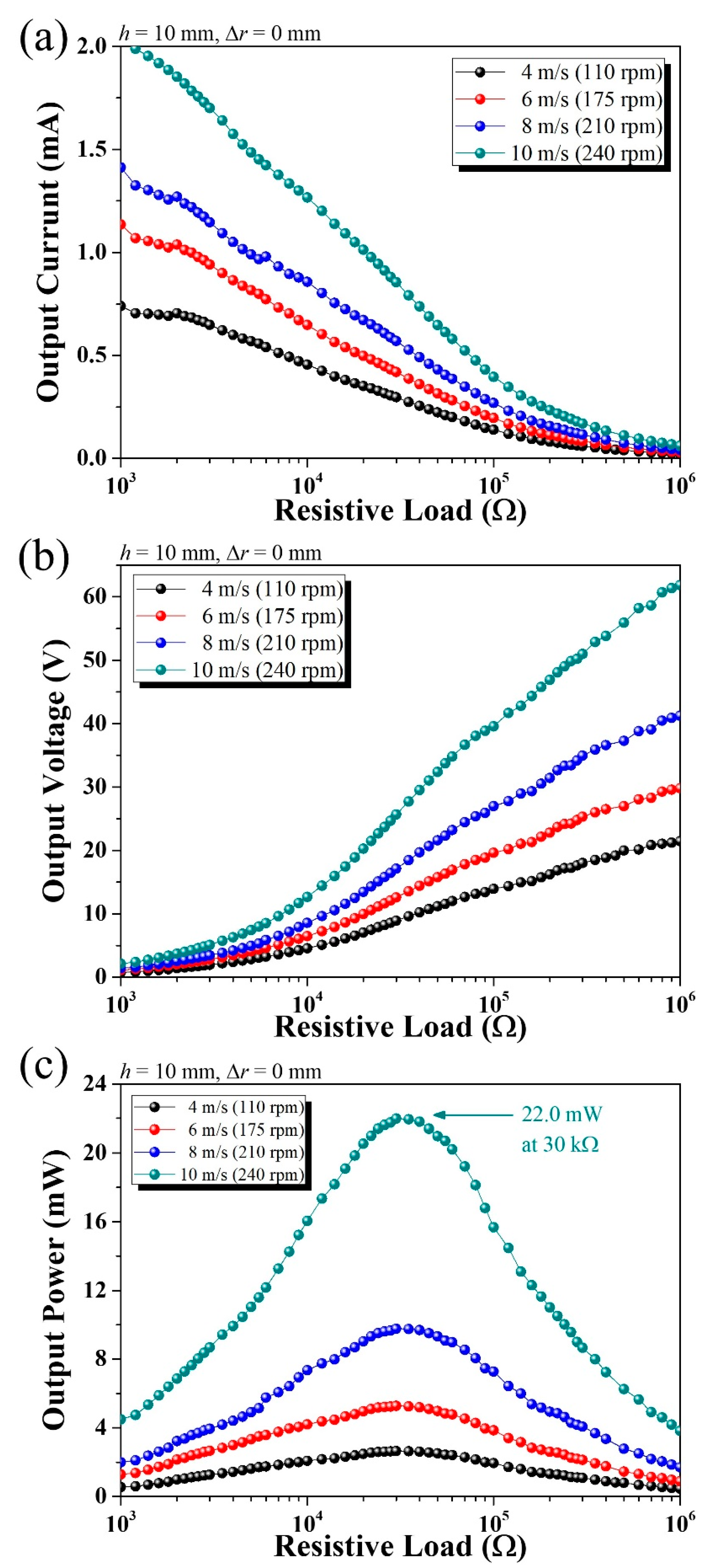
The energy harvesting performance of the wind energy harvester was depicted with variation of the resistive load from 1 kΩ to 1 MΩ. The output current, the output voltage, and the output power under a parallel electric connection of the piezoelectric cantilever array are plotted as a function of the wind speed when it ranged from 4 m/s to 10 m/s in
Figure 9a–c, respectively. The increment of 2 m/s of the wind speed from 4 m/s to 10 m/s corresponded to the following amplitudes of the rpm: 110, 175, 210, and 240, respectively. It was not tested at the higher rpm of 240 because the corresponding wind speed is sufficiently high as 10 m/s and because the output power would be reduced during operation away from the resonant frequency, as confirmed in
Figure 4c. With an increase in the resistive load, the output current tended to decrease but the output voltage increased. As expected, an increase in the wind speed could result in an enhancement of both the output voltage and the current. The output power, which equals the output voltage multiplied by the output current, shows a peak near 30 kΩ of the resistive load for all cases of the wind speed. The output power at the wind speed of 4 m/s was slightly low at 3 mW but reached a maximum value of approximately 22 mW with a further increase in the wind speed to 10 m/s. In
Table 3, the resultant energy harvesting characteristics are summarized in detail. As the vertical distance between the magnets decreases, the magnitude of the magnetic force applied increases; this effect appears as an increase in output power of the piezoelectric material. When the height decreases from 14 mm to 13 mm, the magnetic force increases about 1.2 times, and when the height decreases by 1 mm to 10 mm, the magnetic force again increases about 1.2 times. It can be seen that the output power shows a trend similar to those of magnetic force. In addition, according to Equation (8) below, the energy of the wind is proportional to the cube of the wind speed [
43].
Here,
P is wind power,
ρ is air density,
A is area, and
V is wind velocity. However, the generation amount of the wind energy harvester shows a behavior different from that of the wind energy change trend, which is a result of the complex influence of the natural frequency at which the piezoelectric cantilever is deformed at the maximum; to investigate this, further studies are required. The normalized power density can be obtained in consideration of the volume of the cantilever and the total harvester. The normalized power density, calculated from the volume of the cantilever and the total harvester volume, is summarized in
Table 4. The wind energy harvesting performance of the proposed wind energy harvester will make it possible for this device to power many low-power applications, such as smart sensor systems.


